A-level CIE P2P3 w07_ms_2
Testo Saveris 2配置指南说明书

Testo Saveris 2 Configuration To activate Advanced License billing, install first all loggers under the Basic License. To activate an Advanced License, click at the link at your Cloud account page and license fees will be auto calculated.This guide will explain how to create a testo Saveris 2 Cloud account and connect data loggers.Information for minimal system requirements are at the end of this document. Ensure that the system meets the requirements. Please follow the setup instructions in order. The cloud account must becreated first before turning the data logger on. Once the account has been setup, turn on the data logger and connect it to a network. Troubleshooting, FAQ, and system behaviors are covered in this document.Register your testo Saveris 2 or testo 1601. On your PC, Go to https:///2. Use the Register Now button.3. *********************************************************.(Note: Check your Spam/Junk folder if you do not receive the confirmation)4. Confirm your email address within the confirmation mail.(Note: User has 48 hours to confirm their email address to be fully registered)5. Log back to the account.Setting up the testo 1601. Pull tab from the battery compartment, on the back of the testo 160.2. Check front display for Battery Icon (if not replace with fresh batteries)3. Mount with Screws/Anchors/ Magnetic Mounting Plate.(sold separately at Testo, Part Number: 0554 2001)Cloud account Setup Assistant1. Use the USB to connect logger to the computer when logged on to Saveris 2 Cloud account.2. On your computer, select a logger icon with + sign at the upper right corner of the page. Ignore the QR code Appsuggestion. Press the Connect the Wi-Fi logger link.3. When the form is filled out save it to the Saveris 2 data logger.4. Follow steps, and at the last step don’t wait for the Cloud icon on the logger. Disconnect USB from the Task Bar, thendisconnect cable and logger will start connecting to the Wi-Fi and the Cloud account.Notes:If the 160 IAQ does not connect, press the reset button once and this should allow the logger to connect.USB must be safely ejected from the computer. Failure to safely eject will corrupt the embedded file on the logger.To override auto selected Country temperature units setting go to User / User Settings and select the temperature unit from the drop-down selection.•The E-52 error shows that the logger is presently attached to another account.•To remove the logger from its original account, log on, go to Configuration / Wi-Fi data logger, select logger Details in the right column.•Press the Deactivate button at top of the page.•Scroll to the bottom of the page and press the red Remove Data Logger button.•Log out of the account and log back, and if the logger shows up grayed out at the Dashboard listing, click the arrow at the left to delete associated data.•Press shortly the logger button to complete transfer of the delete information.• The logger is now free to be attached to another account.Hot Spot Mode1. Log on to the testo Saveris 2 Cloud account and copy the Account ID (Configuration/Account ID), close the web page.2. Make sure the Wi-Fi adapter is turned on, and the Ethernet cable is pulled out.3. Press the logger button for more than 3 seconds to get LED into continuous green blinking. CONF message on thelogger display confirms the hot spot connection.4. On the computer at Wi-Fi connections connect to Testo Saveris 2 network.5. Open browser and enter 192.168.1.1 at the URL line.6. Fill the form and save, there will be confirmation message on the logger screen.7. A steady Cloud icon on the display indicates connectionNote:USB must be safely ejected from the computer. Failure to safely eject will corrupt the embedded file on the logger. USB Method (for connection to PC using Microsoft Windows OS Only)1. Copy Account ID from your testo Saveris 2 Cloud account (Configuration / Account ID)2. Logger USB connection – open WifiConf.pdf file3. Insert account ID to the form field, fill in name of the network (SSID) and network password. Save configuration(green button) to the logger using Windows File Explorer. Make sure that .xml file is saved to the Saveris 2 drive, not any other folder on your computer.4. Disconnect USB from the Task Bar, then disconnect cable.5. A steady Cloud icon on the display indicates connection to the Cloud website.Note:USB must be safely ejected from the computer. Failure to safely eject will corrupt the embedded file on the logger.testo Saveris 2 / testo 160 work only on 2.4 GHz Wi-Fi. Be sure to select a 2.4 GHz Wi-Fi network.Note: In most institutions, IT permission to install is required, especially on high security networks.NOTE: The MAC Address for the device can be found on the back label. Please keep the MAC Address available.The following browser and router ports must be open:• Browser (Microsoft Edge, Firefox, Google Chrome, Safari): MQTT Port 443 (https)• Router:Port 8883 TCP Secure MQTT (Message Queue Telemetry Transport over SSL)Port 123 UDP Network Time Protocol (NTP)Port 53 TCP Domain Name SystemPort 53 UDP Domain Name SystemCan the Wi-Fi data logger be connected to the PC using any USB cable?• We recommend that you use the USB cable supplied with the Wi-Fi data logger to guarantee stable data transmission.Longer USB cables are suitable for the power supply only.Can the Wi-Fi data logger also be used in networks with WPA2 Enterprise encryption?• testo 160 data loggers can be used in networks with the following WPA2 Enterprise encryption methods.WPA2 Enterprise: EAP-TLS, EAP-TTLS-TLS, EAP-TTLS-MSCHAPv2, EAP TTLS-PSK, EAP-PEAP0-TLS, EAP-PEAP0-MSCHAPv2, EAP-PEAP0-PSK, EAP-PEAP1-TLS, EAP-PEAP1-MSCHAPv2, EAP-PEAP1-PSK, WPA Personal, WPA2 (AES), WPA (TKIP), WEPThe XML configuration file is not being applied by the Wi-Fi data logger, what can I do?• Depending on the operating system, there may be difficulties with the data transfer if the configuration file name has been changed. Leave the default file name.The humidity sensor has been stored at a high temperature (> 30 °C) and in very high humidity (> 80% RH) for a long period of time, what can I do?• The sensor requires a long period of time to regenerate itself again. This process can be accelerated by storing the sensor in a well-ventilated location at a high temperature(> 30 °C} and in low humidity(< 20% RH) for at least 12 hours.The Wi-Fi data logger’s wireless connection to the access point was interrupted, what can I do?1. Press the control key on the Wi-Fi data logger to start searching for a Wi-Fi connection manually.2. Change the alignment or position of the Wi-Fi data logger or the access point (Wi-Fi router).Signal Description LED flashes green every 30 seconds (IAQ)Normal stateLED flashes green at one-second intervals (for 5 min, then 1 long red flash) Configuration mode (hotspot) - press button > 3 secLED flashes green every 200 ms (for 10 seconds)Configuration app: During hotspot mode pressbutton < 3 secLED gives 2 red flashes Connection to Wi-Fi failed (incorrect SSID, In-correct SSID password, incorrect account ID orincorrect account password, attempt to log the160IAQ into the testo Saveris 2 Cloud.If XML is correct, LED gives 1 long green flashIf XML is incorrect, LED gives 3 red flashesConfiguration via USB/PDFLED gives 2 green flashes Connection to Wi-Fi and Cloud successful LED gives 1 long red flash Alarm activated due to limit value violationLED gives 5 green flashes Reset Wi-Fi data logger to factory settingsPress key > 20 secLED gives 1 green flash (measurement data col-lected)Send measurement data to the testo Saveris 2 Cloud (website): press key < 3 secLED gives 4 red flashes Batteries expiredLED flashes alternately green and red Firmware update via USB or wirelessThe error codes can be read out using a web browser via a smartphone/tablet or PC. Press the probe button for 3 seconds. Then enter the following IP address 192.168.1.1 in the web browser.The Wi-Fi data logger (160 IAQ) is displaying error code E03, E04, E05 or E09, what can I do?• An error has occurred in the Wi-Fi data logger. The error will automatically be corrected by the firmware of the Wi-Fi data logger. After a few seconds, the error code should no longer be displayed, you do not need to do anything.The Wi-Fi data logger (160 IAQ) is displaying error code E12, what can I do?• The configuration file WifiConfig.xml indicates an error. Use the Quick Start Guide to create a new configuration file and save this on the Wi-Fi data logger.The Wi-Fi data logger (160 IAQ) is displaying error code E12, what can I do?• The configuration file WifiConfig.xml indicates an error. Use the Quick Start Guide to create a new configuration file and save this on the Wi-Fi data logger.The Wi-Fi data logger (160 IAQ) is displaying error code E23, what can I do?• The most common reason for this error is low battery. Insert new batteries into the Wi-Fi data logger.• If this does not solve the problem: Reset the Wi-Fi data logger to its factory settings. To do this, press and hold down the control key for> 20 s until the display goes blank. If the error code continues to be displayed, then there is a hardware problem. Please contact our Customer Service.The Wi-Fi data logger (160 IAQ) is displaying error code E26, what can I do?• The access point (Wi-Fi router) has no connection to the internet. Check the access point’s internet connection.• The routing within the network infrastructure is not working, check whether too many terminal devices are logged into the access point.The Wi-Fi data logger (160 IAQ) is displaying error code E32, what can I do?The Wi-Fi data logger has not obtained an IP address. There are 2 possible reasons for this error:• The network password is incorrect. Check the password of the Wi-Fi network. Use the Quick Start Guide to create a new configuration file with the correct password and save this on the Wi-Fi data logger.• The access point (Wi-Fi router) has a MAC filter or does not permit the integration of new devices. Check the settings for the access point.The Wi-Fi data logger (160 IAQ) is displaying error code E35, what can I do?• The Wi-Fi data logger has not received any reply to its test ping from the access point (Wi-Fi router). Make sure that a ping to the gateway is allowed within the access point configuration.The Wi-Fi data logger (160 IAQ) is displaying error code E36, what can I do?No DNS available or accessible. Contact the operator of the Wi-Fi network.The Wi-Fi data logger is displaying error code E41, what can I do? The Wi-Fi data logger cannot obtain any current time from a time server ().• The access point (Wi-Fi router) has no connection to the internet. Check the access point’s internet connection.• The NTP port (123/UDP) of the access point (Wi-Fi router) is not open. Check whether the NTP port (123/UDP) is opened.The Wi-Fi data logger (160 IAQ) is displaying error code E51, what can I do?The Wi-Fi data logger was not able to connect to the testo Saveris 2 Cloudd.• If the Wi-Fi data logger has already been connected to the testo Saveris 2 Cloud and this connection is suddenly no longer possible: The testo Saveris 2 Cloud servers are not currently accessible. The servers will be monitored and should be accessible again within a few hours.• If the Wi-Fi data logger has not yet been connected to the testo Saveris 2 Cloud: The TCP ports (1883 or 8883) of the access point (Wi-Fi router) are not open. Check whether the TCP ports (1883 or 8883) are open in both directions.The Wi-Fi data logger (160 IAQ) is displaying error code E52, what can I do?• The Wi-Fi data logger could not log into the testo Saveris 2 Cloud because it is already logged into another account.Please log the Wi-Fi data logger out of the existing account first.The Wi-Fi data logger (160 IAQ) is displaying error code E63, what can I do?The Wi-Fi data logger could not send any data to the testo Saveris 2 Cloud.• The internet connection was interrupted during the transmission. Check whether there is a stable connection from the Wi-Fi data logger to the access point (Wi-Fi router). Check the access point’s internet connection. The data will be transferred during the next communication cycle. Alternatively: Initiate data transmission manually by pressing the control key on the Wi-Fi data logger.• The testo Saveris 2 Cloud server was not able to process the request for data storage. The servers will be monitored and should be accessible again within a few hours.The Wi-Fi data logger (160 IAQ) is displaying error code E69, what can I do?• The Account ID contained in the configuration file is missing or is not valid. Create a new configuration file and save this on the Wi-Fi data logger.• An attempt was made to log the testo 160 E Wi-Fi data logger into the testo Saveris 2 Cloud without any external probes connected. Connect the required external probes before logging inThe Wi-Fi data logger (160 IAQ) is displaying error code E75, what can I do?• A firmware update for the Wi-Fi data logger failed.• The internet connection was interrupted during the transmission or the data was not received intact by the Wi-Fi data logger for other reasons. Check whether there is a stable connection from the Wi-Fi data logger to the access point (Wi-Fi router). Check the access point’s internet connection. The data will be transferred during the next communication cycle.• Alternatively: Initiate data transmission manually by pressing the control key on the Wi-Fi data logger.The Wi-Fi data logger (160 IAQ) is displaying the warning message Err AccountlD, what can I do?• The Account lD contained in the configuration file is not valid.• Use the Quick Start Guide to create a new configuration file and save this on the Wi-Fi data logger.The Wi-Fi data logger (160 IAQ) is displaying the warning message no AccountlD, what can I do?• There is no AccountlD in the configuration file.• Use the Quick Start Guide to create a new configuration file and save this on the Wi-Fi data logger.The Wi-Fi data logger (160 IAQ) is displaying the warning message no License, what can I do?• The Wi-Fi data logger cannot be logged in because the number of Wi-Fi data loggers permitted to log in has been exceeded or your testo 160 license has expired.• Log off another Wi-Fi data logger, extend or renew your testo 160 license.The Wi-Fi data logger (160 IAQ) is displaying the warning message not Active, what can I do?• The Wi-Fi data logger has been deactivated. It is not storing, and therefore not sending, any measurement data to the testo Saveris 2 Cloud.• Activate the Wi-Fi data logger (under Configuration --> Wi-Fi data logger) when the Wi-Fi data logger needs to store and send measurement data again.Testo Data Loggers will operate under free Basic License with limitations as listed at the table below.Register now: https:///。
华为调试
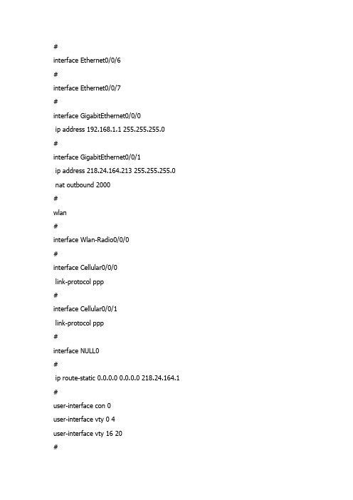
#interface Ethernet0/0/6#interface Ethernet0/0/7#interface GigabitEthernet0/0/0ip address 192.168.1.1 255.255.255.0#interface GigabitEthernet0/0/1ip address 218.24.164.213 255.255.255.0 nat outbound 2000#wlan#interface Wlan-Radio0/0/0#interface Cellular0/0/0link-protocol ppp#interface Cellular0/0/1link-protocol ppp#interface NULL0#ip route-static 0.0.0.0 0.0.0.0 218.24.164.1 #user-interface con 0user-interface vty 0 4user-interface vty 16 20#return[Huawei-GigabitEthernet0/0/1]nat ser pro tcp glo 218.24.164.213 www in 192.168.1 .200 8080Error: The address conflicts with interface or ARP IP.[Huawei-GigabitEthernet0/0/1]di th[V200R001C01]#interface GigabitEthernet0/0/1ip address 218.24.164.213 255.255.255.0nat outbound 2000#return[Huawei-GigabitEthernet0/0/1]undo nat ou 2000[Huawei-GigabitEthernet0/0/1]nat ser pro tcp glo 218.24.164.213 www in 192.168.1 .200 8080Error: The address conflicts with interface or ARP IP.[Huawei-GigabitEthernet0/0/1][Huawei-GigabitEthernet0/0/1]di th[V200R001C01]#interface GigabitEthernet0/0/1ip address 218.24.164.213 255.255.255.0#return[Huawei-GigabitEthernet0/0/1]nat ou 2000 ?address-group IP address-group of NATinterface Specify the interface<cr> Please press ENTER to execute command[Huawei-GigabitEthernet0/0/1]nat ou 2000 ad[Huawei-GigabitEthernet0/0/1]nat ou 2000 address-group 1Error: The address conflicts with interface or ARP IP. [Huawei-GigabitEthernet0/0/1]di cu[V200R001C01]#snmp-agent local-engineid 800007DB034C1FCC45D3A6 snmp-agent#voice#http server enable#drop illegal-mac alarm#dhcp enable#set transceiver-monitoring disable#acl number 2000rule 0 permit source 192.168.1.0 0.0.0.255rule 1 deny#aaaauthentication-scheme defaultauthorization-scheme defaultaccounting-scheme defaultdomain default[Huawei-GigabitEthernet0/0/1][Huawei-GigabitEthernet0/0/1][Huawei-GigabitEthernet0/0/1][Huawei-GigabitEthernet0/0/1]qu[Huawei]acl 2000[Huawei-acl-basic-2000]di th[V200R001C01]#acl number 2000rule 0 permit source 192.168.1.0 0.0.0.255rule 1 deny#return[Huawei-acl-basic-2000]undo rule 0[Huawei-acl-basic-2000]undo rule 1[Huawei-acl-basic-2000]rule permi ?fragment Check fragment packetnone-first-fragment Check the subsequence fragment packet source Specify source addresstime-range Specify a special timevpn-instance Specify a VPN-Instance<cr> Please press ENTER to execute command [Huawei-acl-basic-2000]rule permi[Huawei-acl-basic-2000]qu[Huawei]int g0/0/1[Huawei-GigabitEthernet0/0/1]di th[V200R001C01]#interface GigabitEthernet0/0/1ip address 218.24.164.213 255.255.255.0#return[Huawei-GigabitEthernet0/0/1]nat ou[Huawei-GigabitEthernet0/0/1]nat outbound 2000 add 1Error: The address conflicts with interface or ARP IP.[Huawei-GigabitEthernet0/0/1]qu[Huawei]acl 2000[Huawei-acl-basic-2000]di th[V200R001C01]#acl number 2000rule 5 permit#return[Huawei-acl-basic-2000]undo rule 5[Huawei-acl-basic-2000]rule 0 per so[Huawei-acl-basic-2000]rule 0 per source ?IP_ADDR<X.X.X.X> Address of sourceany Any source[Huawei-acl-basic-2000]rule 0 per source 192.168.1.0 0.0.0.255 [Huawei-acl-basic-2000]rule 1 de^Error:Ambiguous command found at '^' position.[Huawei-acl-basic-2000]di th[V200R001C01]#acl number 2000rule 0 permit source 192.168.1.0 0.0.0.255#return[Huawei-acl-basic-2000]rule 1 deny ?fragment Check fragment packetnone-first-fragment Check the subsequence fragment packetsource Specify source addresstime-range Specify a special timevpn-instance Specify a VPN-Instance<cr> Please press ENTER to execute command [Huawei-acl-basic-2000]rule 1 deny[Huawei-acl-basic-2000]di th[V200R001C01]#acl number 2000rule 0 permit source 192.168.1.0 0.0.0.255rule 1 deny#return[Huawei-acl-basic-2000]qu[Huawei]int g0/0/1[Huawei-GigabitEthernet0/0/1]di th[V200R001C01]#interface GigabitEthernet0/0/1ip address 218.24.164.213 255.255.255.0#return[Huawei-GigabitEthernet0/0/1]nat ou[Huawei-GigabitEthernet0/0/1]nat outbound 2000 ?address-group IP address-group of NATinterface Specify the interface<cr> Please press ENTER to execute command [Huawei-GigabitEthernet0/0/1]nat outbound 2000 ad 1Error: The address conflicts with interface or ARP IP.[Huawei-GigabitEthernet0/0/1]nat outbound 2000[Huawei-GigabitEthernet0/0/1]di th[V200R001C01]#interface GigabitEthernet0/0/1ip address 218.24.164.213 255.255.255.0nat outbound 2000#return[Huawei-GigabitEthernet0/0/1]dis nat ad[Huawei-GigabitEthernet0/0/1]qu[Huawei]dis nat ad 1NAT Address-Group Information:--------------------------------------Index Start-address End-address--------------------------------------1 218.24.164.213 218.24.164.213--------------------------------------Total : 1[Huawei]di cu[V200R001C01]#snmp-agent local-engineid 800007DB034C1FCC45D3A6 snmp-agent#voice#http server enable#drop illegal-mac alarm#dhcp enable#set transceiver-monitoring disable#acl number 2000rule 0 permit source 192.168.1.0 0.0.0.255rule 1 deny#aaaauthentication-scheme defaultauthorization-scheme defaultaccounting-scheme defaultdomain defaultdomain default_adminlocal-user admin password simple adminlocal-user admin service-type http#firewall zone trust#nat address-group 1 218.24.164.213 218.24.164.213 #interface Ethernet0/0/0#interface Ethernet0/0/1#interface Ethernet0/0/2#interface Ethernet0/0/3#interface Ethernet0/0/4#interface Ethernet0/0/5#interface Ethernet0/0/6#interface Ethernet0/0/7#interface GigabitEthernet0/0/0ip address 192.168.1.1 255.255.255.0#interface GigabitEthernet0/0/1ip address 218.24.164.213 255.255.255.0 nat outbound 2000#wlan#interface Wlan-Radio0/0/0#interface Cellular0/0/0link-protocol ppp#interface Cellular0/0/1link-protocol ppp#interface NULL0#ip route-static 0.0.0.0 0.0.0.0 218.24.164.1 #user-interface con 0user-interface vty 0 4user-interface vty 16 20#return[Huawei][Huawei]int g0/0/1[Huawei-GigabitEthernet0/0/1]di th[V200R001C01]#interface GigabitEthernet0/0/1ip address 218.24.164.213 255.255.255.0nat outbound 2000#return[Huawei-GigabitEthernet0/0/1]nat pro ?^Error: Unrecognized command found at '^' position.[Huawei-GigabitEthernet0/0/1]qu[Huawei]nat ?address-group IP address-group of NATalg Application level gatewaydns-map DNS mappingfilter-mode NAT filter modelink-down Link down reset session functionmapping-mode NAT mapping modeoverlap-address Overlap address pool to temp address pool map static Specify static NAT[Huawei]dis cu[V200R001C01]#snmp-agent local-engineid 800007DB034C1FCC45D3A6snmp-agent#voice#http server enable#drop illegal-mac alarm#dhcp enable#set transceiver-monitoring disable#acl number 2000rule 0 permit source 192.168.1.0 0.0.0.255rule 1 deny#aaaauthentication-scheme defaultauthorization-scheme defaultaccounting-scheme defaultdomain defaultdomain default_adminlocal-user admin password simple adminlocal-user admin service-type http#firewall zone trust#nat address-group 1 218.24.164.213 218.24.164.213 #interface Ethernet0/0/0#interface Ethernet0/0/1#interface Ethernet0/0/2#interface Ethernet0/0/3#interface Ethernet0/0/4#interface Ethernet0/0/5#interface Ethernet0/0/6#interface Ethernet0/0/7#interface GigabitEthernet0/0/0ip address 192.168.1.1 255.255.255.0#interface GigabitEthernet0/0/1ip address 218.24.164.213 255.255.255.0 nat outbound 2000#wlan#interface Wlan-Radio0/0/0#interface Cellular0/0/0link-protocol ppp#interface Cellular0/0/1link-protocol ppp#interface NULL0#ip route-static 0.0.0.0 0.0.0.0 218.24.164.1#user-interface con 0user-interface vty 0 4user-interface vty 16 20#return[Huawei]dis cu[V200R001C01]#snmp-agent local-engineid 800007DB034C1FCC45D3A6 snmp-agent#voice#http server enable#drop illegal-mac alarm#dhcp enable#set transceiver-monitoring disable#acl number 2000rule 0 permit source 192.168.1.0 0.0.0.255rule 1 denyaaaauthentication-scheme defaultauthorization-scheme defaultaccounting-scheme defaultdomain defaultdomain default_adminlocal-user admin password simple adminlocal-user admin service-type http#firewall zone trust#nat address-group 1 218.24.164.213 218.24.164.213 #interface Ethernet0/0/0#interface Ethernet0/0/1#interface Ethernet0/0/2#interface Ethernet0/0/3#interface Ethernet0/0/4#interface Ethernet0/0/5#interface Ethernet0/0/6#interface Ethernet0/0/7#[Huawei][Huawei]undo nat add 1[Huawei]nat ?address-group IP address-group of NATalg Application level gatewaydns-map DNS mappingfilter-mode NAT filter modelink-down Link down reset session functionmapping-mode NAT mapping modeoverlap-address Overlap address pool to temp address pool mapstatic Specify static NAT[Huawei]int g0/0/1[Huawei-GigabitEthernet0/0/1]di th[V200R001C01]#interface GigabitEthernet0/0/1ip address 218.24.164.213 255.255.255.0nat outbound 2000#return[Huawei-GigabitEthernet0/0/1]nat ser pro tcp glo 218.24.164.213 7008 ins 192.168 .1.200 7008Error: The address conflicts with interface or ARP IP.[Huawei-GigabitEthernet0/0/1]di veHuawei Versatile Routing Platform SoftwareVRP (R) software, Version 5.90 (AR1200 V200R001C01)Copyright (C) 2011 HUAWEI TECH CO., LTDHuawei AR1220 Router uptime is 0 week, 0 day, 3 hours, 14 minutesBKP 0 version information:1. PCB Version : AR01BAK1A VER.A2. If Supporting PoE : Yes3. Board Type : AR12204. MPU Slot Quantity : 15. LPU Slot Quantity : 2MPU 0(Master) : uptime is 0 week, 0 day, 3 hours, 14 minutes SDRAM Memory Size : 512 M bytesFlash Memory Size : 256 M bytesNVRAM Memory Size : 512 K bytesMPU version information :1. PCB Version : AR01SRU1A VER.C2. MAB Version : 03. Board Type : AR1220W-S4. CPLD1 Version : 1045. BootROM Version : 225[Huawei-GigabitEthernet0/0/1]di th[V200R001C01]#interface GigabitEthernet0/0/1ip address 218.24.164.213 255.255.255.0nat outbound 2000#return[Huawei-GigabitEthernet0/0/1]undo ip add ?IP_ADDR<X.X.X.X> IP addressbootp Bootp clientbootp-alloc Bootp client allocdhcp Dynamic host configure protocoldhcp-alloc IP address allocunnumbered Share an address with another interface<cr> Please press ENTER to execute command[Huawei-GigabitEthernet0/0/1]undo ip add[Huawei-GigabitEthernet0/0/1]di th[V200R001C01]#interface GigabitEthernet0/0/1nat outbound 2000#return[Huawei-GigabitEthernet0/0/1]nat ser pro tcp glo ?X.X.X.X Global IP address of NATcurrent-interface Address of current interfaceinterface Specify the interface[Huawei-GigabitEthernet0/0/1]nat ser pro tcp glo 218.24.164.213 7008 ?inside Specify inside information of NAT[Huawei-GigabitEthernet0/0/1]nat ser pro tcp glo 218.24.164.213 7008 inside 192. 168.1.200 7008[Huawei-GigabitEthernet0/0/1]di th[V200R001C01]#interface GigabitEthernet0/0/1nat server protocol tcp global 218.24.164.213 7008 inside 192.168.1.200 7008nat outbound 2000#return[Huawei-GigabitEthernet0/0/1]Please check whether system data has been changed, and save data in timeConfiguration console time out, please press any key to log on<Huawei><Huawei><Huawei><Huawei>saThe current configuration will be written to the device.Are you sure to continue? (y/n)[n]:yIt will take several minutes to save configuration file, please wait.......... ...Configuration file had been saved successfullyNote: The configuration file will take effect after being activated<Huawei>。
Mellanox 红帽企业级 Linux(RHEL)7.5 驱动用户手册说明书

Red Hat Enterprise Linux (RHEL) 7.5 DriverUser ManualMellanox Technologies350 Oakmead Parkway Suite 100Sunnyvale, CA 94085U.S.A.Tel: (408) 970-3400Fax: (408) 970-3403© Copyright 2016. Mellanox Technologies Ltd. All Rights Reserved.Mellanox®, Mellanox logo, Accelio®, BridgeX®, CloudX logo, CompustorX®, Connect-IB®, ConnectX®,CoolBox®, CORE-Direct®, EZchip®, EZchip logo, EZappliance®, EZdesign®, EZdriver®, EZsystem®,GPUDirect®, InfiniHost®, InfiniBridge®, InfiniScale®, Kotura®, Kotura logo, Mellanox CloudRack®, MellanoxCloudXMellanox®, Mellanox Federal Systems®, Mellanox HostDirect®, Mellanox Multi-Host®, Mellanox OpenEthernet®, Mellanox OpenCloud®, Mellanox OpenCloud Logo®, Mellanox PeerDirect®, Mellanox ScalableHPC®,Mellanox StorageX®, Mellanox TuneX®, Mellanox Connect Accelerate Outperform logo, Mellanox Virtual ModularSwitch®, MetroDX®, MetroX®, MLNX-OS®, NP-1c®, NP-2®, NP-3®, Open Ethernet logo, PhyX®, PlatformX®,PSIPHY®, SiPhy®, StoreX®, SwitchX®, Tilera®, Tilera logo, TestX®, TuneX®, The Generation of Open Ethernetlogo, UFM®, Unbreakable Link®, Virtual Protocol Interconnect®, Voltaire® and Voltaire logo are registeredtrademarks of Mellanox Technologies, Ltd.All other trademarks are property of their respective owners.For the most updated list of Mellanox trademarks, visit /page/trademarksNOTE:THIS HARDWARE, SOFTWARE OR TEST SUITE PRODUCT (“PRODUCT (S)”) AND ITS RELATEDDOCUMENTATION ARE PROVIDED BY MELLANOX TECHNOLOGIES “AS -IS” WITH ALL FAULTS OF ANYKIND AND SOLELY FOR THE PURPOSE OF AIDING THE CUSTOMER IN TESTING APPLICATIONS THAT USETHE PRODUCTS IN DESIGNATED SOLUTIONS. THE CUSTOMER'S MANUFACTURING TEST ENVIRONMENTHAS NOT MET THE STANDARDS SET BY MELLANOX TECHNOLOGIES TO FULLY QUALIFY THE PRODUCT(S)AND/OR THE SYSTEM USING IT. THEREFORE, MELLANOX TECHNOLOGIES CANNOT AND DOES NOTGUARANTEE OR WARRANT THAT THE PRODUCTS WILL OPERATE WITH THE HIGHEST QUALITY. ANYEXPRESS OR IMPLIED WARRANTIES, INCLUDING, BUT NOT LIMITED TO, THE IMPLIED WARRANTIES OFMERCHANTABILITY, FITNESS FOR A PARTICULAR PURPOSE AND NONINFRINGEMENT ARE DISCLAIMED. INNO EVENT SHALL MELLANOX BE LIABLE TO CUSTOMER OR ANY THIRD PARTIES FOR ANY DIRECT,INDIRECT, SPECIAL, EXEMPLARY, OR CONSEQUENTIAL DAMAGES OF ANY KIND (INCLUDING, BUT NOTLIMITED TO, PAYMENT FOR PROCUREMENT OF SUBSTITUTE GOODS OR SERVICES; LOSS OF USE, DATA,OR PROFITS; OR BUSINESS INTERRUPTION) HOWEVER CAUSED AND ON ANY THEORY OF LIABILITY,WHETHER IN CONTRACT, STRICT LIABILITY, OR TORT (INCLUDING NEGLIGENCE OR OTHERWISE) ARISINGIN ANY WAY FROM THE USE OF THE PRODUCT(S) AND RELATED DOCUMENTATION EVEN IF ADVISED OFTHE POSSIBILITY OF SUCH DAMAGE.Table of ContentsDocument Revision History (5)1Firmware Burning (6)2Port Type Management (7)3Modules Loading and Unloading (8)4Important Packages and Their Installation (9)5SR-IOV Configuration (10)5.1Setting up SR-IOV in ConnectX-3/ConnectX-3 Pro (10)6Default RoCE Mode Setting (12)7PXE over InfiniBand Installation (13)Table 1: Document Revision History (5)Table 1: Document Revision History1 Firmware Burning1.Check the device’s PCI address.lspci | grep MellanoxExample:00:06.0 Infiniband controller: Mellanox Technologies MT27520 Family[ConnectX-3 Pro]2.Identify the adapter card's PSID.# mstflint -d 81:00.0 qImage type: FS2FW Version: 2.36.5000FW Release Date: 26.1.2016Rom Info: type=PXE version=3.4.718 devid=4103Device ID: 4103Description: Node Port1 Port2Sys imageGUIDs: e41d2d0300b3f590 e41d2d0300b3f591 e41d2d0300b3f592e41d2d0300b3f593MACs: e41d2db3f591 e41d2db3f592VSD:PSID: MT_10901110193.Download the firmware BIN file from the Mellanox website that matches your card'sPSID: → Support/Education→Support Downloader4.Burn the firmware.# mstflint -d <lspci-device-id> -i <image-file> b5.Reboot your machine after the firmware burning is completed.2 Port Type ManagementConnectX®-3/ConnectX®-3 Pro/ConnectX®-4/ConnectX®-4 Lx/ConnectX®-5/ConnectX®-5 Ex ports can be individually configured to work as InfiniBand or Ethernetports. By default both ConnectX®-4 VPI ports are initialized as InfiniBand ports. If youwish to change the port type use the mstconfig after the driver is loaded.1.Install mstflint tools.yum install mstflint2.Check the device’s PCI address.lspci | grep MellanoxExample:00:06.0 Infiniband controller: Mellanox Technologies MT27520 Family[ConnectX-3 Pro]e mstconfig to change the link type as desired IB – for InfiniBand, ETH – for Ethernet.mstconfig –d <device pci> s LINK_TYPE_P1/2=<ETH|IB|VPI>Example:# mstconfig -d 00:06.0 s LINK_TYPE_P1=ETHDevice #1:----------Device type: ConnectX3ProPCI device: 00:06.0Configurations: Current NewLINK_TYPE_P1 IB(1) ETH(2)Apply new Configuration? ? (y/n) [n] : yApplying... Done!-I- Please reboot machine to load new configurations.4.Reboot your machine.3 Modules Loading and UnloadingMellanox modules for ConnectX®-2/ConnectX®-3/ConnectX®-3 Pro are:∙mlx4_en, mlx4_core, mlx4_ibMellanox modules for ConnectX®-4/ConnectX®-4 Lx/ ConnectX®-5/ ConnectX®-5 Exare:∙mlx5_core, mlx5_ibIn order to unload the driver, you need to first unload mlx*_en/ mlx*_ib and then themlx*_core module.To load and unload the modules, use the commands below:∙Loading the driver: modprobe <module name># modprobe mlx5_ib∙Unloading the driver: modprobe –r <module name># modprobe –r mlx5_ib4 Important Packages and Their Installationrdma-corerdma-core RDMA core userspace libraries and daemonslibibmad: Low layer InfiniBand diagnostic and management programslibibmad OpenFabrics Alliance InfiniBand MAD libraryopensm: InfiniBand Subnet Manageropensm-libs Libraries used by OpenSM and included utilitiesopensm OpenIB InfiniBand Subnet Manager and management utilitiesIbutils: OpenIB Mellanox InfiniBand Diagnostic Toolsibutils-libs Shared libraries used by ibutils binariesibutils OpenIB Mellanox InfiniBand Diagnostic Toolsinfiniband-diags: OpenFabrics Alliance InfiniBand Diagnostic Toolsinfiniband-diags OpenFabrics Alliance InfiniBand Diagnostic Toolsperftest: IB Performance testsperftest IB Performance Testsmstflint: Mellanox Firmware Burning and Diagnostics Toolsmstflint Mellanox firmware burning toolTo install the packages above run:# yum install libibverbs librdmacm libibcm libibmad libibumad libmlx4libmlx5 opensm ibutils infiniband-diags srptools perftest mstflint rdmacm-utils ibverbs-utils librdmacm-utils -y5 SR-IOV Configuration5.1 Setting up SR-IOV in ConnectX-3/ConnectX-3 Pro1.Install the mstflint tools.# yum install mstflint2.Check the device’s PCI.# lspci | grep MellanoxExample:00:06.0 Infiniband controller: Mellanox Technologies MT27520 Family[ConnectX-3 Pro]3.Check if SR-IOV is enabled in the firmware.mstconfig -d <device pci> qExample:# mstconfig -d 00:06.0 qDevice #1:----------Device type: ConnectX3ProPCI device: 00:06.0Configurations: CurrentSRIOV_EN True(1)NUM_OF_VFS 8LINK_TYPE_P1 ETH(2)LINK_TYPE_P2 IB(1)LOG_BAR_SIZE 3BOOT_PKEY_P1 0BOOT_PKEY_P2 0BOOT_OPTION_ROM_EN_P1 True(1)BOOT_VLAN_EN_P1 False(0)BOOT_RETRY_CNT_P1 0LEGACY_BOOT_PROTOCOL_P1 PXE(1)BOOT_VLAN_P1 1BOOT_OPTION_ROM_EN_P2 True(1)BOOT_VLAN_EN_P2 False(0)BOOT_RETRY_CNT_P2 0LEGACY_BOOT_PROTOCOL_P2 PXE(1)BOOT_VLAN_P2 1IP_VER_P1 IPv4(0)IP_VER_P2 IPv4(04.Enable SR-IOV:mstconfig –d <device pci> s SRIOV_EN=<False|True>5.Configure the needed number of VFsmstconfig –d <device pci> s NUM_OF_VFS=<NUM>NOTE: This file will be generated only if IOMMU is set in the grub.conf file (byadding “intel_iommu=on” to /boo t/grub/grub.conf file).6.[mlx4 devices only] Create/Edit the file /etc/modprobe.d/mlx4.conf:options mlx4_core num_vfs=[needed num of VFs] port_type_array=[1/2 for IB/ETH],[ 1/2 for IB/ETH]Example:options mlx4_core num_vfs=8 port_type_array=1,17.[mlx5 devices only] Write to the sysfs file the number of needed VFs.echo [num_vfs] > sys/class/net/ib2/device/sriov_numvfsExample:# echo 8 > /sys/class/net/ib2/device/sriov_numvfs8.Reboot the driver.9.Load the driver and verify that the VFs were created.# lspci | grep mellanoxExample:00:06.0 Network controller: Mellanox Technologies MT27520 Family[ConnectX-3 Pro]00:06.1 Network controller: Mellanox Technologies MT27500/MT27520 Family [ConnectX-3/ConnectX-3 Pro Virtual Function]00:06.2 Network controller: Mellanox Technologies MT27500/MT27520 Family [ConnectX-3/ConnectX-3 Pro Virtual Function]00:06.3 Network controller: Mellanox Technologies MT27500/MT27520 Family [ConnectX-3/ConnectX-3 Pro Virtual Function]00:06.4 Network controller: Mellanox Technologies MT27500/MT27520 Family [ConnectX-3/ConnectX-3 Pro Virtual Function]00:06.5 Network controller: Mellanox Technologies MT27500/MT27520 Family [ConnectX-3/ConnectX-3 Pro Virtual Function]00:06.6 Network controller: Mellanox Technologies MT27500/MT27520 Family [ConnectX-3/ConnectX-3 Pro Virtual Function]00:06.7 Network controller: Mellanox Technologies MT27500/MT27520 Family [ConnectX-3/ConnectX-3 Pro Virtual Function]00:06.0 Network controller: Mellanox Technologies MT27500/MT27520 Family [ConnectX-3/ConnectX-3 Pro Virtual Function]For further information, refer to section Setting Up SR-IOV MLNX_OFED User Manual.6 Default RoCE Mode Setting1.Mount the configfs file.# mount -t configfs none /sys/kernel/config2.Create a directory for the mlx4/mlx5 device.# mkdir -p /sys/kernel/config/rdma_cm/mlx4_0/3.Validate what is the used RoCE mode in the default_roce_mode configfs file.# cat /sys/kernel/config/rdma_cm/mlx4_0/ports/1/default_roce_modeIB/RoCE v14.Change the default RoCE mode,∙For RoCE v1: IB/RoCE v1∙For RoCE v2: RoCE v2# echo "RoCE v2" >/sys/kernel/config/rdma_cm/mlx4_0/ports/1/default_roce_mode# cat /sys/kernel/config/rdma_cm/mlx4_0/ports/1/default_roce_modeRoCE v2# echo "IB/RoCE v1" >/sys/kernel/config/rdma_cm/mlx4_0/ports/1/default_roce_mode# cat /sys/kernel/config/rdma_cm/mlx4_0/ports/1/default_roce_modeIB/RoCE v17 PXE over InfiniBand InstallationPXE over InfiniBand infrastructure has additional parameter in the Boot Loader file forloading the necessary modules and interfaces and for allowing sufficient time to get the link.To install RHEL from PXE using the IPoIB interfaces, add the following parameters to theBoot Loader file, located in the var/lib/tftpboot/pxelinux.cfg directory, at thePXE server:bootdev=ib0 ksdevice=ib0 net.ifnames=0 biosdevname=0 rd.neednet=1rd.bootif=0 rd.driver.pre=mlx5_ib,mlx4_ib,ib_ipoib ip=ib0:dhcp.dhcp.retry=10 .timeout.iflink=60 .timeout.ifup=80.timeout.carrier=80Example:default RH7.5prompt 1timeout 600label RH7.5kernelappend bootdev=ib0 ksdevice=ib0 net.ifnames=0 biosdevname=0 rd.neednet=1rd.bootif=0 rd.driver.pre=mlx5_ib,mlx4_ib,ib_ipoib ip=ib0:dhcp.dhcp.retry=10 .timeout.iflink=60 .timeout.ifup=80.timeout.carrier=80。
思科身份服务引擎安装指南,版本 3.0说明书

思科身份服务引擎安装指南,版本3.0首次发布日期:2021年8月26日上次修改日期:2021年8月26日Americas HeadquartersCisco Systems,Inc.170West Tasman DriveSan Jose,CA95134-1706USATel:408526-4000800553-NETS(6387)Fax:408527-0883THE SPECIFICATIONS AND INFORMATION REGARDING THE PRODUCTS IN THIS MANUAL ARE SUBJECT TO CHANGE WITHOUT NOTICE.ALL STATEMENTS, INFORMATION,AND RECOMMENDATIONS IN THIS MANUAL ARE BELIEVED TO BE ACCURATE BUT ARE PRESENTED WITHOUT WARRANTY OF ANY KIND, EXPRESS OR ERS MUST TAKE FULL RESPONSIBILITY FOR THEIR APPLICATION OF ANY PRODUCTS.THE SOFTWARE LICENSE AND LIMITED WARRANTY FOR THE ACCOMPANYING PRODUCT ARE SET FORTH IN THE INFORMATION PACKET THAT SHIPPED WITH THE PRODUCT AND ARE INCORPORATED HEREIN BY THIS REFERENCE.IF YOU ARE UNABLE TO LOCATE THE SOFTWARE LICENSE OR LIMITED WARRANTY, CONTACT YOUR CISCO REPRESENTATIVE FOR A COPY.The Cisco implementation of TCP header compression is an adaptation of a program developed by the University of California,Berkeley(UCB)as part of UCB's public domain version of the UNIX operating system.All rights reserved.Copyright©1981,Regents of the University of California.NOTWITHSTANDING ANY OTHER WARRANTY HEREIN,ALL DOCUMENT FILES AND SOFTWARE OF THESE SUPPLIERS ARE PROVIDED“AS IS"WITH ALL FAULTS. CISCO AND THE ABOVE-NAMED SUPPLIERS DISCLAIM ALL WARRANTIES,EXPRESSED OR IMPLIED,INCLUDING,WITHOUT LIMITATION,THOSE OF MERCHANTABILITY,FITNESS FOR A PARTICULAR PURPOSE AND NONINFRINGEMENT OR ARISING FROM A COURSE OF DEALING,USAGE,OR TRADE PRACTICE.IN NO EVENT SHALL CISCO OR ITS SUPPLIERS BE LIABLE FOR ANY INDIRECT,SPECIAL,CONSEQUENTIAL,OR INCIDENTAL DAMAGES,INCLUDING,WITHOUT LIMITATION,LOST PROFITS OR LOSS OR DAMAGE TO DATA ARISING OUT OF THE USE OR INABILITY TO USE THIS MANUAL,EVEN IF CISCO OR ITS SUPPLIERS HA VE BEEN ADVISED OF THE POSSIBILITY OF SUCH DAMAGES.Any Internet Protocol(IP)addresses and phone numbers used in this document are not intended to be actual addresses and phone numbers.Any examples,command display output,network topology diagrams,and other figures included in the document are shown for illustrative purposes only.Any use of actual IP addresses or phone numbers in illustrative content is unintentional and coincidental.All printed copies and duplicate soft copies of this document are considered uncontrolled.See the current online version for the latest version.Cisco has more than200offices worldwide.Addresses and phone numbers are listed on the Cisco website at /go/offices.Cisco and the Cisco logo are trademarks or registered trademarks of Cisco and/or its affiliates in the U.S.and other countries.To view a list of Cisco trademarks,go to this URL:https:///c/en/us/about/legal/trademarks.html.Third-party trademarks mentioned are the property of their respective owners.The use of the word partner does not imply a partnership relationship between Cisco and any other company.(1721R)©2020Cisco Systems,Inc.保留所有权利。
VigorACS 2 Quick Start Guide

V i g o r A C S2U n i f i e d M a n a g e m e n t S y s t e mManual Version: 1.0Software Version: V2.3.1Date: August 17, 2018Table of Contents1. Platform for Windows 7 or 10 (5)1.1 Installation for Java (5)1.2 Installation for MariaDB (9)1.3 Installation for VigorACS 2 (14)1.4 StartMySQL/MariaDB Databse (23)1.5 Start VigorACS (23)2. Platform for Linux (25)2.1 Installation for MariaDB, Java and VigorACS (25)2.2 Start MySQL/MariaDB Databse (31)2.3 Start VigorACS (31)2.4 Edit VigorACS IP (31)3. Registering VigorACS 2 (32)3.1 Registration for VigorACS via Windows Platform (32)4. Configuration on CPE Device (37)4.1 Set ACS URL on CPE (37)4.2 Invoke Remote Management for CPE (39)4.3 Enable WAN Connection on CPE (40)5. Troubleshooting (42)1.P l a t f o r m f o r W i n d o w s7o r10Please follow the procedure listed below to install VigorACS 2 completely. The installation for different platforms might be different.T o start up the VigorACS, the normal procedure is listed as follows:(I)Installation for Java(II)Installation for MariaDB(III)Installation for VigorACS 2(IV)Start MySQL/MariaDB Database.(V)Edit VigorACS IP.(VI)Start VigorACS.Info VigorACS 2 can be operated only by a host with 64-bit operation system.1.1I n s t a l l a t i o n f o r J a v a1.Install Java by clicking “java-1.8.0-openjdk-1.8.1.151-1.b12…” to execute the installation.2.The first page will be shown as follows. Click Next to get into next page.3.Then, check “I accept the terms…” and click the Next button.4.In this page, optional features will be listed for you to specify the destination folder forJAVA driver installation. Choose the one you need and click Next.5.In the following page, just click Install.6.Wait for a while to install the required features.7.When the following page appears, the installation is completed. Click Finish to exit theinstalling program.1.2I n s t a l l a t i o n f o r M a r i a D B1.Install MariaDB by clicking “mariadb-10.2.10-winx64” (based on your PC condition) it toexecute the installation.2.When the welcome screen appears, please click Next for next step.3.On this dialog box, check the box of “I accept the terms….” and click Next.4.Select the way for the features to be installed. Then click Next.5.If you want to configure password for MariaDB server, please check Modify password… andtype the password. It depends on your request. Otherwise, simply click Next.6.Modify the default instance properties if required. Then click Next.7.On this dialog box, click Next.8.On this dialog box, click Install.9.The installation program starts to install required files for MariaDB to your computer. Waitfor several seconds.10.After finishing the configuration, please click Finish to exit the wizard.1.3I n s t a l l a t i o n f o r V i g o r A C S2It is time to install VigorACS main program. Follow the steps below.1.Click Setup to run VigorACS 2 setup wizard.2.When the following dialog appears, choose Local Database / Remote Database and clickNext.3.Select the directory that MariaDB being installed (done in 1.2) and click Next4.In this dialog box, choose Rebuild Database (for rebuilding the VigorACS database) orUpgrade Database (for upgrading the database). For the first time using, please choose Rebuild Database. Then click Next.5.Click Next. If you have configured MySQL/MariaDB previously and specified password for it,you have to type the password in this page and then click Next.6.Set the maximum memory and minimum memory. Click Next.7.Setup ACS HTTP and HTTPS port, we'll suggest using others port instead of default 80 and443 port to prevent conflict.Info The port number defined here will be used for opening VigorACS later.8.Determine the home path and click Next. The default directory used by this program isC:\Users. You can modify it if you want and please make sure the length of directory is not over 100 characters, otherwise you might encounter problem of VigorACS in installation.9.Determine the destination folder and click Next. The default directory used by thisprogram is C:\Program Files\VigorACS. You can modify it if you want and please make sure the length of directory is not over 100 characters, otherwise you might encounter problem of VigorACS in installation.10.Determine the start menu folder and click Next. The default directory used by thisprogram is VigorACS. You can modify it if you want and please make sure the length of directory is not over 100 characters, otherwise you might encounter problem of VigorACS in installation.11.In this dialog, check the box of “Create a desktop shortcut” for your necessity. Click Next.12.Now, the program is ready to install necessary features and files to your computer. Pleaseclick Install to start.13.Please wait for a while to complete the installation.14.While installing, the following screen will appear to show that MariaDB has been activated.Please wait for next dialog appearing.15.Now the program has completed the installation of VigorACS 2. Click Finish to exit it.1.4S t a r t M y S Q L/M a r i a D B D a t a b s eAfter installing VigorACS, install program will register MySQL/MariaDB to Windows Service.MySQL /MariaDB will startup automatically after installing VigorACS or rebooting system.Normally, you don't need to worry about this step on Windows. But if you find any problems on VigorACS, you should check mysql/mariadb first. Please go to Windows Service check theMySQL/MariaDB Service starts or not.1.5S t a r t V i g o r A C S1.Login VigorACS. Use a web browser and type “localhost:portnumber”. Note that the portnumber must be the one defined for HTTP and HTTPS port while installing VigorACS. Forexample, if HTTPS is defined as 8011, then the URL will be “localhost:8011”.2.The login page of VigorACS will be shown as the following. Please type “root” as user nameand “admin123” as password and type the authentication code. Then click Login.3.For the first time to access into the web user interface, a warning message appears first.Please click the Change password button to change the default password for networksecurity. If not, click Cancel to access into the web user interface of VigorACS and changethe password later.4.After clicking Login, main screen of VigorACS 2 will be shown as below.2.P l a t f o r m f o r L i n u xT o start up the VigorACS under Linux, please execute"/usr/local/vigoracs/VigorACS/bin/vigoracs.sh" instruction. A list of menu items will be shown as follows.1.Start mysql/mariadb2.Shutdown mysql/mariadb3.Start VigorACS4.Shutdown VigorACS5.Edit bind IP of VigorACS Server (please key in IP or server name)6.Set the Max. and Min. memory value of running java (it will be valid after restartingVigorACS)7.View the Max. and Min. memory value of running java8.exit2.1I n s t a l l a t i o n f o r M a r i a D B,J a v a a n d V i g o r A C SFollow the steps listed below to install VigorACS under Linux:1.Login Linux with root or the root privilege.2.Download the ACS installation tar.bz2 package and extract it via below command:#bzip2 -cd VigorACS_Unix_Like_xxxxxx_xxxxx.tar.bz2 | tar xvf -or#tar -jxv -f VigorACS_Unix_Like_xxxxxx_xxxxx.tar.bz23.Decompress the setup packagesbzip2 -cd VigorACS_Unix_Like_xxxxxx_xxxxx.tar.bz2 |tar xvf –4.Change the permissions mode of install.sh and uninstall.sh.chmod 755 install.shchmod 755 uninstall.sh5.Execute ./install.sh installation file.Please make sure you have /usr/bin/sh first. If you don't have /usr/bin/sh, please enter the command:#ln -s /bin/sh /usr/bin/sh6.The system will ask to create vigoracs, enter “y” to proceed.7.Next, the system will ask you to install xfonts-base and fontconfig, just enter “y” toproceed.8.Next, please select the item number which you want to execute. Note that VigorACSsupports Linux OS. The program will detect the system you have in your computer.(1) Install mysql/mariadb(2) Change root password and security configuration of mysql/mariadb(3) Install or Upgrade java(4) Install VigorACS(5) Upgrade VigorACS(6) Redirect the database path of VigorACS to remote host (7) Exitinput select num:InfoIf your computer has installed MariaDB and java previously, ignore theinstallation of them. Otherwise, install all the required items (MariaDB, Java and VigorACS) for your system. Item number 5 is used to upgrade VigorACS, so it is not necessary for you to execute for the first time of installation.9. Input 1 to install MariaDB first. Notice that it will setup blank as default password. You canchange the password by using the following command.#/usr/local/mysql/bin/mysqladmin--defaults-file=/usr/local/mysql/f -u root password 'newpassword'InfoThe password configured by the command above will be effective onlywhen there is no password set for database root before.Follow the instructions on the screen to finish the MariaDB installation.ter, input 2 to change root password and security configuration of mysql/mariadb.Info The password set in this step is used for VigorACS 2 to login database.11.Input 3 to install Java.Follow the instructions on the screen to finish the Java installation.12.Input 4 to install VigorACS. It is suggested to use ACS customized MariaDB database. Whenasked to enter MariaDB password, press “Enter” if you haven’t changed the password via the command. Then, confirm that TR-069 database has been installed successfully.Wait and follow the instructions on the screen to finish the installation.13. Now, input 6 to redirect the database path of VigorACS to remote host. For remotedatabase, please execute such step on remote host.14. Input 7 to finish and exit the installation.Info 1 Step 13 is required for establishing remote database only . You can ignore it while building local database.Info 2T o prevent port conflicts, we'll suggest that using other ports for HTTP and HTTPS instead of default 80 and 443.2.2S t a r t M y S Q L/M a r i a D B D a t a b s eAfter installing VigorACS, mysql/mariadb daemon has started. You can to see it using "ps-ef|grep mysql" instruction. Use the menu item 1 / 2 to start / shutdown mysql/mariadb.2.3S t a r t V i g o r A C SAfter installing VigorACS, access “/usr/local/vigoracs/VigorACS/bin”, execute “./vigoracs.sh”.Select item 3 to start VigorACS.If you ever reboot the machine after installing VigorACS, just select item 1 to startmysql/mariadb first. Then, select item 3 to start VigorACS.2.4E d i t V i g o r A C S I PWhen starting the VigorACS at first time on Linux, startup program will ask you input Server IP or input Enter key by using the IP address of the host. Once you input the IP address, VigorACS will keep it on startway.txt. Next time, if you want to change it, you can select item 5 to editstartway.txt using vi editor.3. R e g i s t e r i n g V i g o r A C S 2For the first time to activate VigorACS 2, the system will ask you to register VigorACS 2 onto DrayT ek MyVigor server . Refer to the following sections to register VigorACS 2 on differentplatforms.Info 1 While installing VigorACS, install program will register MySQL/MariaDB toWindows Service. MySQL/MariaDB will startup automatically after installingVigorACS or rebooting system. Normally , you don't need to worry about this step on Windows. But if you find any problems on VigorACS, you should checkmysql/mariadb first. Please go to Windows Service check the MySQL/MariaDB Service starts or not.Info 2After installing VigorACS, the software will startup automatically . Normally ,you don't need to worry about this step on Windows. But, if you find any problem on VigorACS, you could shut down VigorACS and start VigorACS again. 3.1 R e g i s t r a t i o n f o r V i g o r A C S v i a W i n d o w s P l a t f o r mBelow shows the steps to register VigorACS 2:1. Login VigorACS. Use a web browser and type “localhost:portnumber”. Note that the portnumber must be the one defined for HTTP and HTTPS port while installing VigorACS. For example, if HTTPS is defined as 8011, then the URL will be “localhost:8011”.2. The login page of VigorACS will be shown as the following. Please type “root” as user nameand “admin123” as password and type the authentication code. Then click Login.Info“root” and “admin123” are default settings.3. A License Error dialog appears as follows. Simply click Active.4. A login page for MyVigor web site will be popped up automatically . Type your account (username) and password in this page. Then, click Login.InfoIf you do not have any account, simply click Create an account now to create a new one for using the service provided by MyVigor web site.5.MyVigor will verify and authenticate if the user account you typed is allowed to access intothe web site. If yes, the following screen will appear.6.Type a nickname for VigorACS and click Add.7.After clicking Add, you can see the following screen. Click OK.8.You will get a device information page as shown below. If you are the new user of VigorACS,you can get a free charge of 30-day service of VigorACS. Simply click the Trial button.9.From the following screen, check the box of “I have read and accept the above….” andclick Next.10.In the page below, click Register.11.When the VigorACS License Information page appears, the service is ready for you to use.Click Login to ACS to use VigorACS service.12.The login page will appear as follows. Type the default settings of User Name (root) andPassword (admin123) and type the authentication code. Then, click Login.13.Now, the main screen of VigorACS will be shown as follows.4.C o n f i g u r a t i o n o n C P E D e v i c e4.1S e t A C S U R L o n C P ET o manage CPEs through VigorACS, you have to set ACS URL on CPE first and set username and password for VigorACS.1.Connect one CPE (e.g., Vigor2862 series).2.Open a web browser (for example, IE, Mozilla Firefox or Netscape) on your computer andtype http://192.168.1.1.3.Please type username and password on the window. If you don’t know the correctusername and password, please consult your dealer to get them. In this section, we takethe figures displayed on Windows as examples.4.Go to System Maintenance -> TR-069.•Please set URL as the following and type username and password for ACS server,for the connected CPE with authentication:http://{IP address of VigorACS}:80/ACSServer/services/ACSServlet•Please set URL as the following, for the connected CPE without authentication: http://{IP address of VigorACS}:80/ACSServer/services/UnAuthACSServlet•Please set URL as the following, for the connected CPE with authentication and the data transmission between CPE and VigorACS 2 with encryption (SSL).https://{IP address of VigorACS}:443/ACSServer/services/ACSServlet•Please set URL as the following, for the connected CPE without authentication but the data transmission between CPE and VigorACS 2 with encryption (SSL)https://{IP address of VigorACS}:443/ACSServer/services/UnAuthACSServlet5.Fill Username and Password for VigorACS 2 Server for authentication. Please enter as thefollowing:Username: acsPassword: password6.For the username and password of CPE client, it is not necessary for you to type them.7.Click Enable for Periodic Inform Settings.4.2I n v o k e R e m o t e M a n a g e m e n t f o r C P EYou have to make sure that the CPE device you want to connect supports VigorACS 2 features.Please consult your dealer if you have no idea in it.1.Suppose WAN IP of CPE device has been setup successfully. And you can access into Internetwithout difficulty.2.Login the device (e.g., Vigor2862) by web.3.Go to System Maintenance>>Management.4.Check Allow management from the Internet to set management access control.4.3E n a b l e W A N C o n n e c t i o n o n C P EYou have to make sure the CPE device you want to connect has been configured properly and can access into Internet.1.Login the device (e.g., Vigor2862) by web.2.Open WAN>>Internet Access.3.Choose Static or Dynamic IP as Access Mode and click Details Page for WAN2.4.The following web page appears. Click Enable and Specify an IP address. Enter correctWAN IP address, subnet mask and gateway IP address for your CPE. Then click OK.VigorACS 2 Quick Start Guide41InfoReboot the CPE device and re-log into VigorACS 2. CPE which has registered to VigorACS 2 will be captured and displayed on the home page of VigorACS 2.VigorACS 2 Quick Start Guide42 5. T r o u b l e s h o o t i n gWhen you try to invoke VigorACS 2 and get the following error message, please locate the file of “server .log ” from C:/Program Files/VigorACS/server/default/log and send the file to yourdealer for further assistance.For Linux system, please locate the file of “server .log ” from/usr/local/vigoracs/VigorACS/server/default/log/ and send the file to your dealer for further assistance.。
IBM E34 High Availability IMS Using TCP IP 说明书
9 © IBM Corporation 2003
IMS Connect Tips
IMS Connect client TCP/IP environment
Protocol to access print servers on a TCP/IP network
Spool print to a remote print server Monitor progress of remote printing Cancel print job spooled to the remote print server
CHNG ALTPCB2, LU1xx ISRT
5
© IBM Corporation 2003
Program-to-Program
Application Socket calls TCP/IP
TCP/IP
IMS Connect
VTAM
IMIMSS
6
Socket Application Basic Design
3270 emulator TELNET TCP/IP
3270 Emulation
TN3270 Login userid password Emulators
3270 VT100 ... TELNET TCP IP
V
MVS T TCP/IP A
M
TELNET
IMS
TSO CICS
BEGINVTAM
** LOGMODES **
Bind socket S to a local address (Port)
ISA安装升级配置和操作手册centos系统安装
服务器RAID配置1.1超微服务器RAID方法超微服务器主板集成raid功能,但只支持raid1的设定1.1.1BIOS配置Main Serial ATA-》SATA controller Mode Option:SATA Controller mode Option:EhancedSATA RAID CodeBase:Adaptec重启1.1.2主板RAID卡设置按ctrl +大写‘A’即ctrl+ shift+a进入Array Configuration Utility设置Main Menu -》Configure Driver根据帮助提示,按INS键,加入两个硬盘,按“Enter”保存-》Y确认Main Menu -》Create Array,加入上面添加的那两块硬盘进入Array Propertites,按“Enter”,选择不同属性,F1可用选择帮助选择RAID-1(mirror)方式Stripe option选择:quick initaizing,快速初始化如果选择clear就是低格清零,很慢。
选择完成按“Done”。
1.2Dell/IBM 服务器RAID方法Dell/IBM等品牌服务器多设有raid卡,由于是硬raid,因此不需要手动设定,但raid 级别需根据raid卡而定,公司常用的DELL-R710型号需要通过配置页面手工设置,具体配置方法为:开机按F10进入配置界面:选择USC设置,选择语言和键盘,设置语言为中文选择RAID配置:RAID级别设置为RAID1:2操作系统安装配置2.1Centos系统安装以安装centos5.5为例,共有两个版本:64位和32位,安装时请注意区分版本。
2.1.1系统安装步骤系统版本:CentOS 5.5 64位将镜像刻成光盘,设置BIOS将CDROM设置为第一启动(超微服务器默认光盘启动)启动画面:通过提示,按ENTER进入图形安装模式。
检测安装媒介,这里选Skip,跳过。
求生之路2 最全控制台指令
求生之路2控制台命令按“~”控制台输入sv_cheats 0 关闭作弊(默认)sv_cheats 1 打开作弊sv_alltalk 0 打开全局语音通话(默认)sv_alltalk 1 关闭全局语音通话*命令中"1"表示打开"0"表示关闭status 游戏信息,可查看本游戏IP和玩家ping 游戏延迟查看connect ... 连接指定IP就行游戏sensitivity 3.0 鼠标速度(默认)volume 1.0 音量(默认)cl_showfps 1 屏幕显示fps数值和地图名称net_graph 0,1,2,3 显示当前客户端参数如fps 网络连接上传速度下载速度和ping值pause 暂停游戏kill 自杀------------------------------------------------------------------------------------------ 创建游戏------------------------------------------------------------------------------------------ hostname 创建指定主机名的游戏hostname Left 4 Dead 2 创建指定主机名为"Left 4 Dead 2" 的游戏map 创建指定地图,并开始游戏游戏模式map 地图名coop 战役模式map 地图名versus 对抗模式map 地图名realism 写实模式map 地图名survival 生存模式map 地图名scavenge 清道夫模式map 地图名teamscavenge 团队清道夫模式map 地图名teamversus 团队对抗模式地图名参考如下:map c1m1_hotel 死亡中心第一张地图map c2m1_highway 黑色狂欢节第一张地图map c3m1_plankcountry 沼泽激战第一张地图map c4m1_milltown_a 暴风骤雨第一张地图map c5m1_waterfront 教区第一张地图游戏中更换地图changelevel 地图名玩家不掉线更换地图changelevel 地图名游戏模式更换游戏模式,需要重新开始游戏才能生效更改游戏难度z_difficulty Easy Easy, Normal, Hard, Expert, 对应简单、普通、困难、专家survivor_friendly_fire_factor_easy 0.2 简单难度队友伤害值(默认:0.2 关闭:0) survivor_friendly_fire_factor_normal 0.2 普通难度队友伤害值(默认:0.2 关闭:0) survivor_friendly_fire_factor_hard 0.4 困难难度队友伤害值(默认:0.4 关闭:0) survivor_friendly_fire_factor_expert 1.0 专家难度队友伤害值(默认:1 关闭:0) survivor_burn_factor_easy 0.2 简单难度火焰伤害值(默认:0.2 关闭:0)survivor_burn_factor_normal 0.2 普通难度火焰伤害值(默认:0.2 关闭:0)survivor_burn_factor_hard 0.4 困难难度火焰伤害值(默认:0.4 关闭:0)survivor_burn_factor_expert 1 专家难度火焰伤害值(默认:1 关闭:0)管理员指令:say 内容说话[say 大家好]玩家会见到对话框入面: [Concole: 大家好]say_team 内容同上kick 玩家名踢人z_difficulty Normal 游戏难度(Easy, Normal, Hard, Impossible)differences 查看你的伺服器设定与伺服器设定的预设值有什么不同restart 重新开始游戏------------------------------------------------------------------------------------------游戏作弊------------------------------------------------------------------------------------------god 1 无敌buddha 打不死noclip 穿墙impulse 10 全部武器,子彈give health 加满血give ammo 加满弹夹respawn 死亡后复活仅限于复活自己,且在出生点复活sv_infinite_ammo 1 无限弹药不换弹夹melee_range 70 (预设为70)近战武器的伤害范围数值越高能砍得越远sb_dont_bash 1 强制电脑队友不用手推sb_dont_shoot 1 强制电脑队友不开枪sb_takecontrol * 游戏中在4个人物之间切换控制(*代表Ellis,Nick,Rochelle,Coach也可以不要后缀为随机切换)sb_move 0 所有电脑队友停止移动sb_escort 1 强制所有电脑队友保护你紧跟在你身边sb_open_fire 1 强制所有电脑队友不停的开火sb_crouch 1 强制所有电脑队友蹲下sb_flashlight 1 强制所有电脑队友使用手电筒(-1为强制不使用)sb_give * 给予所有电脑一个道具或武器(*代表物品名如fireaxe参见下面的道具参数)sb_give_random_weapon 给每个电脑随机分配一把武器cl_showfps 1 显示帧数(1=显示帧数和地图名2=显示帧数和平滑率3=服务器信息4=显示帧数和日志文件)thirdpersonshoulder 第三人称模式(再输入一次可还原为第一人称)nb_d elete_all 踢掉所有电脑队友和附近的僵尸和所有的特殊僵尸(但是所有的僵尸还是会刷新) nb_blind 1 所有电脑僵尸都看不到你(但是撞到僵尸还是会攻击你)cl_drawhud 0 关闭所有的界面包括准星(现实模式)------------------------------------------------------------------------------------------事件控制director_force_panic_event 立即爆发僵尸暴走事件director_panic_forever 1 僵尸暴走事件不停,即一波接一波(默认:0) 可用上一个命令激活生效,或者下一次爆发时生效。
- 1、下载文档前请自行甄别文档内容的完整性,平台不提供额外的编辑、内容补充、找答案等附加服务。
- 2、"仅部分预览"的文档,不可在线预览部分如存在完整性等问题,可反馈申请退款(可完整预览的文档不适用该条件!)。
- 3、如文档侵犯您的权益,请联系客服反馈,我们会尽快为您处理(人工客服工作时间:9:00-18:30)。
UNIVERSITY OF CAMBRIDGE INTERNATIONAL EXAMINATIONSGCE Advanced Subsidiary Level and GCE Advanced LevelMARK SCHEME for the October/November 2007 question paper9709 MATHEMATICS9709/02Paper 2, maximum raw mark 50This mark scheme is published as an aid to teachers and candidates, to indicate the requirements of the examination. It shows the basis on which Examiners were instructed to award marks. It does not indicate the details of the discussions that took place at an Examiners’ meeting before marking began.A l l Examiners are instructed that a lternative correct answers and unexpected approaches in candidates’ scripts must be given marks that fair l y ref l ect the re l evant know l edge and ski l ls demonstrated.Mark schemes must be read in conjunction with the question papers and the report on the examination.• CIE will not enter into discussions or correspondence in connection with these mark schemes.CIE is publishing the mark schemes for the October/November 2007 question papers for most IGCSE, GCE Advanced Leve land Advanced Subsidiary Leve lsy l labuses and some Ordinary Leve lsyllabuses.Mark Scheme NotesMarks are of the following three types:M Method mark, awarded for a valid method applied to the problem. Method marks are not lost for numerical errors, algebraic slips or errors in units.However, it is not usually sufficient for a candidate just to indicate an intentionof using some method or just to quote a formula; the formula or idea must beapplied to the specific problem in hand, e.g. by substituting the relevantquantities into the formula. Correct application of a formula without theformula being quoted obviously earns the M mark and in some cases an Mmark can be implied from a correct answer.A Accuracy mark, awarded for a correct answer or intermediate step correctlyobtained. Accuracy marks cannot be given unless the associated methodmark is earned (or implied).B Mark for a correct result or statement independent of method marks.• When a part of a question has two or more "method" steps, the M marks are generally independent unless the scheme specifically says otherwise; and similarly when there are several B marks allocated. The notation DM or DB (or dep*) is used to indicate that a particular M or B mark is dependent on an earlier M or B (asterisked) mark in the scheme. When two or more steps are run together by the candidate, the earlier marks are implied and full credit is given.• The symbol √ implies that the A or B mark indicated is allowed for work correctly following on from previously incorrect results. Otherwise, A or B marks are given for correct work only. A and B marks are not given for fortuitously "correct" answers or results obtained from incorrect working.• Note: B2 or A2 means that the candidate can earn 2 or 0.B2/1/0 means that the candidate can earn anything from 0 to 2.The marks indicated in the scheme may not be subdivided. If there is genuine doubt whether a candidate has earned a mark, allow the candidate the benefit of the doubt. Unless otherwise indicated, marks once gained cannot subsequently be lost,e.g. wrong working following a correct form of answer is ignored.• Wrong or missing units in an answer should not lead to the loss of a mark unless the scheme specifically indicates otherwise.• For a numerical answer, allow the A or B mark if a value is obtained which is correct to 3 s.f., or which would be correct to 3 s.f. if rounded (1 d.p. in the case of an angle). As stated above, an A or B mark is not given if a correct numerical answer arises fortuitously from incorrect working. For Mechanics questions, allow A or B marks for correct answers which arise from taking g equal to 9.8 or 9.81 instead of10.The following abbreviations may be used in a mark scheme or used on the scripts:AEF Any Equivalent Form (of answer is equally acceptable)AG Answer Given on the question paper (so extra checking is needed to ensure that the detailed working leading to the result is valid)BOD Benefit of Doubt (allowed when the validity of a solution may not be absolutely clear)CAO Correct Answer Only (emphasising that no "follow through" from a previous error is allowed)CWO Correct Working Only - often written by a ‘fortuitous' answerISW Ignore Subsequent WorkingMR MisreadPA Premature Approximation (resulting in basically correct work that is insufficiently accurate)S OS S ee Other S olution (the candidate makes a better attempt at the same question)S R S pecial Ruling (detailing the mark to be given for a specific wrong solution, or a case where some standard marking practice is to be variedin the light of a particular circumstance)PenaltiesMR -1 A penalty of MR -1 is deducted from A or B marks when the data of a question or part question are genuinely misread and the object anddifficulty of the question remain unaltered. In this case all A and B marksthen become "follow through √" marks. MR is not applied when thecandidate misreads his own figures - this is regarded as an error inaccuracy. An MR-2 penalty may be applied in particular cases if agreedat the coordination meeting.PA -1 This is deducted from A or B marks in the case of premature approximation. The PA -1 penalty is usually discussed at the meeting.1 State indefinite integral of the form k In(2x + 1), where k = 21, 1 or 2M1State correct integral 21In(2x + 1) A1 Use limits correctly, allow use of limits x = 4 and x = 1 in an incorrect form M1 Obtain given answerA1 [4] 2 (i) Use the iterative formula correctly at least once M1 Obtain final answer 2.29A1 Show sufficient iterations to justify its accuracy to 2 d.p. (must be working to 4 d.p.) – 3 iterations are sufficientB1 [3](ii) State equation x =32x +24x, or equivalent B1Derive the exact answer α (or x ) = 312, or equivalentB1 [2]3 (i) Obtain critical values4 and 6 B1 State answer 4 < y < 6 B1 [2](ii) Use correct method for solving an equation of the form 3x = a, where a > 0M1 Obtain one critical value, i.e. either 1.26 or 1.63 A1 State answer 1.26 < x <1.63 A1 [3]4 State derivative 2 – sec 2 x , or equivalentB1 Equate derivative to zero and solve for x M1O btain x = π41, or 0.785 (± 45° gains A1)A1 O btain x = – π41, (allow negative of first solution) A1√O btain corresponding y -values π21– 1 and –π21+ 1, ± 0.571 A1 [5]5 (i) Substitute x = –2 and equate to zero M1 O btain answer a = 3 A1 [2](ii) At any stage state that x = –2 is a solution B1EITHER: Attempt division by x + 2 and reach a partial quotient of 3x 2+ kx M1Obtain quadratic factor 3x 2 + 2x – 1A1 O btain solutions x = – 1 and x = 31A1OR: Obtain solution x = –1 by trial or inspection B1btain solution x = 31similarly B2[4]6 (i) State answer R = 17, allow 289 B1 Use trig formula to find α M1 O btain α = 61.93°, (1.08 radians) A1 [3](ii) Carry out evaluation of sin 1−(14/17) ≈55.44°, or equivalentM1 Obtain answer 117.4°, (2.06 radians) A1 Carry out correct method for second answer M1 Obtain answer 186.5° and no others in the range (3.255 radians) A1√ [4] [Ignore answers outside the given range.]7 (i) Expand and use sin 2A formula M1 Use cos 2A formula at least once M1 Obtain any correct expression in terms of cos 2x and sin 2x only – can be implied A1 Obtain given answer correctly A1 [4](ii) State indefinite integral 5x – 2sin 2x – 23cos 2xB2 [Award B1 if one error in one term] Substitute limits correctly – must be correct limits M1O btain answer 41(5π – 2), or exact simplified equivalent A1 [4]8 (i) Differentiate using product or quotient rule M1 Obtain derivative in any correct form A1 Equate derivative to zero and solve for x M1 O btain answer x = 2 correctly, with no other solution A1 [4](ii) Find the gradient of the curve when x = 1, must be simplified, allow 0.368 B1 Form the equation of the tangent when x = 1 M1 Show that it passes through the origin A1 [3] (iii) State or imply correct ordinates 0.36787…, 0.54134…, 0.44808… B1 Use correct formula, or equivalent, correctly with h = 1 and three ordinates M1 Obtain answer 0.95 with no errors seen A1 [3]。