RA-800Ⅰ系列可视控制器型单元器件说明书
CYR800L技术说明书V1 (1)

2
保护原理 .................................................................................................................................... 7
2.1 2.2 2.3 2.4 2.5 2.6 2.7 2.8 2.9 2.10 2.11 2.12 2.13 2.14 2.15 2.16 2.17 2.18 2.19 2.20 2.21 2.22 2.23 2.24 2.25 2.26 2.27 2.28 2.29 2.30 2.31 2.32 2.33 2.34 2.35 CT 回路断线告警 .................................................................................................................................... 7 PT 回路断线告警 .................................................................................................................................... 7 控制电源失电告警................................................................................................................................... 8 合闸回路断线告警..................................................
源信电气 综合选型手册说明书

综合选型手册| | | 触摸屏 | PLC变频器 | 伺服驱动器光伏逆变器同步机控制器YUANXIN2021年012月6日版权所有。
指标如有变更,恕不另行通知。
SHENZHEN YUANXIN ELECTRIC TECHNOLOGIES CO., LTD深圳公司地址:深圳市光明区马田街道中粮云景广场第1栋2211室东莞分公司地址:东莞市黄江镇振鹏街六号虹牛新时代产业园C栋4/5层网址:01目 录YX2000系列迷你无感矢量型变频器3YX9000系列高性能矢量型变频器15Y 3800系列球磨机一体柜X 23YX9300系列空压机专用变频器2702YX9500系列空压机单变频一体机驱动器29YX3900系列光伏水泵专用变频器24YX9100系列拉丝机专用变频器25YX6000系列中压变频器30操作键盘31深圳市源信电气技术有限公司成立于2009年,是一家专注于自动化传动与控制产品研发、生产、销售及服务的高科技企业,企业位于交通便捷的深圳市光明区马田街道中粮云景广场第1栋,先后被认定为深圳市双软企业,国家级高新技术企业。
源信电气自成立以来,始终坚持“以人为本、求实创新、技术领先、稳步发展”的经营方针,把人才作为企业发展的核心理念,荟萃行业精英,将自动化行业先进技术与优秀的管理经验相结合,为行业用户提供可靠的产品与全方位的解决方案。
源信电气人才结构合理,拥有多名核心技术骨干,皆具有十多年国内、国际知名变频器品牌的研发经验。
因此,源信电气依靠多年专业的研发、生产能力和品质管控经验,使企业在激烈的市场竞争中始终保持竞争力,实现企业快速、稳定的发展。
源信电气产线丰富,截至目前已拥有变频器 、伺服驱动器 、光伏逆变器 、同步机控制器、 触摸屏 、PLC等多种类、多个系列、一百多种规格产品,完全满足自动化传动控制领域各种工况需求,广泛用于石油、化工、塑胶、线缆、印染、市政生活(污水处理)、机床等行业。
我们着眼于未来行业化需求、以市场为导向、以客户需求为中心的研发和生产理念,以高可靠性、高性能化、行业化、个性化、环保化为产品核心诉求,不断进取,用可靠的品质和真诚的服务来面对广大客户,为发展民族电力电子产业而继续前行!公司简介YP5000系列软起动器32YX3600系列背负式变频器34Y L 10系列可编程控制器35应用案例39V9系列高性能矢量型变频器22YX-80系列永磁变频空气压缩机36YX9200系列同步机驱动器26YX9400系列张力控制专用变频器28YS系列工业触摸屏37YX3000系列通用矢量型变频器7YX2000系列迷你无感矢量型变频器YX2000系列变频器是本公司采用全新理念自主开发的一系列高性能,电流矢量型、低噪音变频器。
General Electric 800系列控制器设备说明说明书

Product DataTYPICAL WIRING DIAGRAMSFor Push Button Control StationsBULLETIN800SSTANDARD DUTYA-2750BULLETIN 800TOIL TIGHTB-130BULLETIN 800HHEAVY DUTYCORROSION-RESISTANTBOOTEDA-6178BULLETIN 800HHEAVY DUTYCORROSION-RESISTANTBOOTLESS89-068-gBulletin 800 Control Stations are a rugged line ofdevices designed for use in control circuits Thesecontrol stations offer compact size and dependableoperation to meet most application requirements.Assembled control stations are available in avariety of combinations that can include pushbuttons, selector switches, pilot lights, and specialpurpose devices.Publication 800-2.0 -June, 1989Supersedes Publication 800-2.0 Dated November, 19772Typical Wiring DiagramsFor Push Button Control StationsTable of ContentsGENERAL INFORMATION .......................Page 2 PUSH BUTTON CONTACT SELECTION ...............Page 3 PILOT LIGHT SELECTION ........................Page 4 UNDERVOLTAGE PROTECTION ...................Page 4 UNDERVOLTAGE RELEASE ......................Page 4 EXPLANATION OF SYMBOLS .....................Page 5 START-STOP CONTROL WIRING DIAGRAMSSingle StationBasic Circuit . . . . . . . . . . . . . . . . . . . . Page 9With Direction Indicating Pilot Lights . . . . . . . . . . . . . . . . . Page 9TWO-SPEED CONTROL WIRING DIAGRAMSTwo Speed StationUndervoltage Release . . . . . . . . . . . . . Page11 Ground DetectionWith Push-to-Test Pilot Lights . . . . . . . . . . . . . . . . . . . . . . Page 12General Information This publication is designed to serve as:1. A guide in understanding control circuits.2. A handy reference pointing out the features of the morecommon circuits.3. A guide in the selection and installation of push buttoncontrol stations.Typical Wiring DiagramsFor Push Button Control Stations 3 Genera/ InformationThe control station wiring diagram is a representation ofthe physical station, showing the relative positions ofunits, the suggested internal wiring, and connectionswith the starter.Symbols common to most circuits are explained on Page 5.Less common symbols are explained where they occur.NOTE The symbols used in this publication were adaptedby Allen-Bradley for use in accordance with NEMAstandards. A particular application must satisfy the needsof the user and comply with applicable codes and laws beforeusing any of the typical circuits shown in this publication.Push Button Contact Selection In the United States, contacts are normally rated by NEMA (National Electrical Manufacturers Association) standards. Internationally, contacts are rated by IEC (International Electrotechnical Commission) standards. By matching the contact rating to the load requirements, a proper contact block can be selected. Typically, Push Button contact selection includes the following factors;Voltage/Amperage Requirements, Type of Load and Environment.The contacts selected must be capable of handling the voltage and current to be switched. Control circuit loads are typically called “pilot duty” loads. The load being switched can be a relay, contactor, or similar device that activates a "power circuit”. Pilot Duty devices should not be used to switch horsepower or lighting loads unless they are specifically rated to do so.Solid state applications such as those with programmable controllers may require contacts that are able to switch low current and low voltage resistive loads. Logic reed type contacts provide reliable switching of solid state loads with minimum contact bounce.Contaminated or hazardous location environments may require the use of “sealed switch” type contacts. Applicable codes should always be checked.4Typical Wiring Diagramsfor Push Button Control StationsPilot Light Selection Pilot Light selection is based on the following factors;Voltage, Lamp Requirements, Environment, and Cost.The voltage of a pilot light must match the voltage supply.If both AC and DC voltage sources are available, AC voltageis recommended because it typically extends lamp life onincandescent units. When using an AC source of 120 Voltsor higher, a transformer type pilot light can also increaselamp life.Selection of the type of lamp can also affect lamp life. Thereare three types of lamps commonly used in pilot lights;incandescent, neon, and LED (Light Emitting Diode).Incandescent lamps have the shortest lamp life and aresusceptible to damage from shock and vibration.Incandescent lamps with lower voltages have thickerfilaments and burn cooler, plus are more durable. Neonlamps provide longer lamp life, but have slightly reducedillumination. LED lamps provide the longest lamp life andare the least susceptible to damage from shock andvibration.Illumination requirements are also important whenselecting a lamp. Depending on the color, an incandescelamp can provide brighter illumination when comparedwith a neon or LED lamn.n tCost of the unit in terms of initial expense should also beaddressed. Although it may be cost effective to initiallyinstall a device with a full voltage incandescent lamp, atransformer type, LED or neon unit can reduce downtimecosts through increased lamp life.For more information on Pilot Light selection, refer toAllen-Bradley, Milwaukee, WI.Undervoltage Unless otherwise specified, the circuits provideProtection undervoltage protection or "three wire” control. In theevent of power failure, these circuits are designed to protectagainst automatic restarting when the power returns. Thistype of protection should be used where accidents or damagemight result from unexpected starts.Undervoltage The circuits using undervoltage release or "two wire”Release control are noted in the Table of Contents. With any type ofcontrol, the motor starts automatically after a power failure.Typically, these circuits involve automatic pilot devicessuch as thermostats, float switches, etc.whenOperating Coil of Contactor:Depressing button opens andparent switch does. In this case,M Slow closes lower contacts. Releasing normally open (N.O.) contacts close F Fast button returns contacts to the and normally closed (NC.) contactsRI\JOverload Relay Contacts Jon starter construction).00.\J\J0))1, STARTPUSH BUTTON CIRCUITWIRING DIAGRAM4Reference Point-Identified on starter, corresponds withnumber shown in push button station wiring diagram.Absence of node indicates wires cross with no connection.Power LineSTART23STOP1Type of Station I Catalog NumberrStandard DutyHeavy Duty- Bootless Corrosion-ResistantI800H2HA4RLI1PILOT LIGHTSTARTSTOP‘1START1STOPN.O.Aux.PILOT LIGHT2313nO.L. --cmN.C. Aux.Voltage120V 240v 480V 60Hz 600V 60HzType of StationStandard Duty Catalog Number800S-2SAP 800S-2SAPHeavy Duty General Purpose Catalog Number 800H-2HAR 800H-2HAP 800H-2HAY 800H-2HAVHeavy DutyBootlessOiltight/Corrosion-Resistant Corrosion-Resistant Watertight Catalog Number Catalog Number Catalog Number 800H-2HAR4R 800H-2HAR4RL 800T-2TAR 800H-2HAP4R 800H-2HAP4RL 800T-2TAP 800H-2HAY4R 800H-2HAY4RL 800T-2TAY 800H-2HAV4R800H-2HAV4RL800T-2TAVGROUP OF SINGLE STATIONS-WITH MASTER STOP BUTTONL 1MASTER STARTO.L.1STOPSTOP2-3M lSTARTO.L.r ---------1STOP /START 0 0M2Aux.1---------A momentary contact MASTER STOP button is connected in series with a group of parallel connected circuits. Depressing the button de-energizes all of the circuits.The circuits above are the basic START-STOP circuit shown on Page 6. They could be any of the preceding or following circuits that provide undervoltage protection. Two wire control or undervoltage release circuits are not applicable because they would be energized as the master stop button IS released.SINGLE STATION1ICatalog Number800S-2SBM800H-2HAM800H-2HAM4R800H-2HAM4RL800T-2TAMIQA u x.Operation-The motor can be started or stopped from a number of separate stations by connecting the b a s i c u n i t o n P a g e 6.1Pilot Lights- It is possible to add motor running, stopped, or push-to-test pilot lights to any or all of thestations by connecting the lights to the circuit as shown in the diagrams below. Catalog numbers of theO-0B A u x.BMOTORRUNNINGMOTOR STOPPEDPUSH BUTTON STATIONSPUSH-TO-TEST RUNNINGType of Station Standard Duty Heavy Duty Heavy Duty-Booted Heavy Duty-Bootless Oiltight/WatertightGeneral PurposeCorrosion-ResistantCorrosion-ResistantLCatalog Number800S-2SA800H-2HA800H-2HA4R800H-2HA4RL3:OperationCataloa Number800S-3SA800H-3HA800H-3HA4R800H-3HA4RL800T-3TAREVERSING STATION -WITH DIRECTION INDICATING PILOT LIGHTSL1FOR.L 2IO.L.1STOPREV.2-3R\I IAux.IOperation is the same as the basic circuit, except that separate lights indicate in whichdirection the motor is running.PL.PL.PUSH BUTTON STATIONSVoltage120V 240V 480V, 60Hz 600V, 60HZType of Station &Catalog NumberIHeavy Duty Heavy Duty-Booted Heavy Duty-Bootless Oiltight/WatertightGeneral Purpose Corrosion-Resistant Corrosion-Resistant 800H-3HA2R 800H-3HA2R4R 800H-3HA2R4RL 800T-3TA2R 800H-3HA2P 800H-3HA2P4R 800H-3HA2P4RL 800T-3TA2P 800H-3HA2Y 800H-3HA2Y4R 800H-3HA2Y4RL 800T-3TA2Y 800H-3HA2V800H-3HA2V4R800H-3HA2V4RL800T-3TA2VA2V10Typical Wiring DiagramsFor Push Button Control StationsTwo-Speed Control Wiring DiagramsTWO-SPEED STATION5Depressing the SLOW button begins the following sequence: 1.Coil S is energized. 2. Normally open contacts S close to hold in the SLOW contactor; Normally closed interlock contacts S open to prevent the FAST contactor from being energized.Changing Speeds- Through the use of the normally closed contacts in the SLOW and FAST push button units, it is unnecessary todepress the STOP button before changing speeds. Depressing the SLOW button while running fast: 1. De-energizes the fast control circuit. 2. Energizes and holds in the SLOW contactor as outlined above.Type of Station Catalog NumberPUSH BUTTON STATIONSStandard Duty Heavy Duty Heavy Duty-Booted Heavy Duty-Bootless Oiltight/WatertightGeneral PurposeCorrosion-ResistantCorrosion-Resistant800S-3SF800H-3HF800H-3HF4R800H-3HF4RL800T-3TFTWO-SPEED STATION -WITH SPEED INDICATING PILOT LIGHTSL11STOP.4-I-PUSH BUTTON STATIONSIVoltage120V 240V 480V 60HZ 600V 60HZType of Station &Catalog NumberHeavy Duty Heavy Duty-Booted Heavy Duty-Bootless Oiltight/WatertightGeneral Purpose Corrosion-Resistant Corrosion-Resistant 800H-3HF2R 800H-3HF2R4R 800H-3HF2R4RL 800T-3TF2R 800H-3HF2P 800H-3HF2P4R 800H-3HF2P4RL 800T-3TF2P 800H-3HF2Y 800H-3HF2Y4R 800H-3HF2Y4RL 800T-3TF2Y 800H-3HF2V800H-3HF2V4R800H-3HF2V4RL800T-TF2VPC.I IISTOP1C R 3STOP0 I O 4 ---------Depressing the START Button begins the following sequence: 1. Coil CR is energized; 2. Contacts CR close; 3. Coil M isenergized; 4. Contacts M close to hold in the contactor.Depressing the JOG button energizes Coil M, but normally open contacts CR prevent against the contactor holding in; the motorwill run only as long as the operator holds in the JOG button.PUSH BUTTON STATIONSType of Station Heavy Duty Heavy Duty-Booted Heavy Duty-Bootless General Purpose Oiltight/WatertightCorrosion-Resistant Corrosion-Resistant I .Catalog Number 800H-3HG 800H-3HG4R 800H-3HG4RL 800T-3TGTHERMOSTAT CONTROLLED MOTOR -WITH SELECTOR SWITCHUNDERVOLTAGE RELEASEHIGH L 1 TEMPERATURE OFFCIRCUIT OPERATIONKnob to Auto H a n d &A u t o Selector Switch to Auto-When the temperature is below thepreset value, the thermostat contacts are closed and contactorM is held in. Above this temperature, the contactsautomatically open the circuit. A high temperature cut-out isOff included to open the circuit if the thermostat contacts shouldKnob to Hand HandType ofCatalog Station NumberALLEN-BRADLEY Allen-Bradley has been helping its customers improve productivity and quality for 90 years.A ROCKWELL INTERNATIONAL COMPANY A-B designs, manufactures and supports a broad range of control and automation productsworldwide. They include logic processors, power and motion control devices, man-machineinterfaces and sensors. Allen-Bradley is a subsidiary of Rockwell International, one of theworld’s leading technology companies.With major offices worldwide.Algeria l Argentina l Australia l Austria l Bahrain l Belgium l Brazil l Bulgaria l Canada l Chile l China, PRC l Colombia l Costa Rica l Croatia l Cyprus l Czech Republic l Denmark l Ecuador l Egypt l El Salvador l Finland l France l Germany l Greece l Guatemala l Honduras l Hong Kong l Hungary l Iceland l India l Indonesia l Israel l Italy Turkey l United Arab Emirates l United Kingdom l United States l Uruguay l Venezuela l YugoslaviaWorld Headquarters, Allen-Bradley, 1201 South Second Street, Milwaukee, WI 53204 USA, Tel: (1) 414 382-2000 Fax: (1) 414 382-4444。
变频器说明书大全
变频器说明书大全本文提供多年收藏整理的变频器说明书,全部为高清PDF版本。
如果需要,请发送邮件到XXX索取。
以下是说明书部分目录:1.台安(TAIAN)变频器说明书:包括E2N2V2SV300N310S310EV300K1/N1K200/KxxxxxxxJSE2-EN2.2.台达(DELTA)变频器说明书:包括VFD-AVFD-BVFD-EVFD-FVFD-GVFD-LVFD-M、VFD-SVFD-VVFD-VEVFD-ELVFD-B/PVFD-VL。
3.英威腾(INVT)变频器说明书:包括G9/P9/GS/GLCHECHFCHVCHV110CHV160CHV180.4.XXX(HUILING)变频器说明书:包括H3000.5.信捷(XINJE)变频器说明书:包括V5/F5.6.凯迪华能变频器说明书:包括CD2000.7.酷马(QMA)变频器说明书:包括Q5000Q7000Q9000.8.黎升同步控制器说明书:包括SAD240、SAD280、SAD280i。
9.三品(SANPIN)变频器说明书:包括SKJSPRQ-333.10.能士(XXX)变频器说明书:包括NSA20NSA80.11.台凌(TAILING)变频器说明书:包括TL80TL100TL100H。
12.力普变频器说明书:包括LP100.13.XXX(AMPLE)变频器说明书:包括AMP1000.14.誉强(YUQIANG)变频器说明书:包括YQ3000-MYQ3000-AYQ3000-GYQ3000-A7(上)A7(中)。
A7(下)。
15.格立特(GREAT)变频器说明书:包括VF10VF11VF15VC300VC3100VC3200.16.RICH(XXX)变频器说明书:包括EI-MINIEI-450EI-450MEI-500EI-550EI-600EI-700EI-xxxxxxxxEI Super N、EI。
17.汇川(INOVANCE)变频器说明书:包括MD021 MD280 MD300MD300AMD320MD330.18.XXX(YCDZ)变频器说明书:包括YC-GYC-PTE580软启动器。
洛雷克L19LD800系列监控系统说明书

infOrMatiOn in tHis dOcuMent is suBject tO cHange witHOut nOtice. as Our prOducts are suBject tO cOntinuOus iMprOveMent, L19LD800 SeriesW W W.L O R E X C C T V.C O MQuick start guide r2PACKAGE CONTENTS ANDINSTALLATION GUIDE:☠ System Contents:1 - 19” 8 Channel LCD Monitor with pre-installed HDD *4 - High Res. Color Cameras *4 - 100 ft (30M) Extension Cables *4 - Camera Stands with Mounting Screws *1 - 10 ft Ethernet Cable Intermediateeasyunder 30 minutes under 60 minutes HardwareHi Speedover 60 minutesTimeunder 30 minutes under 15 minutes under 60 minutes Hand Tools Hardware Skills - IntermediateTimeSTEP 3Skill LevelTimeunder 30 minutes under 15 minutes under 60 minutesHand Tools HardwareRouterTimeSkills - Advanced* Installation time may vary based on applicationdevice cOnnectiOns (stand removed)2ascrews2the system has an efficient back panel control that provides a cable management solution.By design the connectors are not easily accessible, in order to secure the connections.it is recommended to remove the stand for initial set-up by simpy unscrewing four screws with a standard screw driver.OPTIONAL - REMOVE MONITOR STANDtilt the monitor (40˚) to allow for easier access to the connectors.TILT MONITOR13your system includes 4 high resolution 6 pin din cameras.CONNECT CAMERAS TO THE MONITORconnect one end of the ethernet cable to one of the router’s (notincluded) Lan pOrts and the other end to the Monitor’s network portlocated at the bottom of the monitor. see picture below showing ageneric Lan/wan connection.CONNECT ETHERNET CABLE4connect one end of the power adaptor to the monitor, the other endto an electrical outlet. this unit powers On once it is plugged in to thepower outlet.tip: Once you are done with the connections, remember to screw thestand back on.CONNECT POWER CABLE5WAN (WIDEAREA NETWORK)LAN (LOCAL AREA NETWORK)TO YOUR COMPUTERTO YOUR MONITORBACK OF THE ROUTER SHOWN6CONTINUEDtip: test the cameras prior to selectinga permanent mounting location bytemporarily connecting the camerasand cables to your system.* connect cameras to extension cablesby aligning the arrows. plug in camerasand cables before mounting the cameras.nOte: the arrow mark on top of the flat side ofthe camera and cable connectors should faceup while inserting to the Monitor.connect the first camera to the cH1 input. follow the same steps toconnect the additional cameras.4aUNIvERSAL DIN TO BNC CABLECONTINUEDthe unit will automatically begin loading when power is connected to the system.INITIAL LOADING SEQUENCEcb7aclick the Menu button on the front panel of the Monitor (or the remote controller) to enter the Main Menu. from the Main Menu move to systeM and press the enter button to go to the date/tiMe menu to activate menu options.SET THE DATE & TIME9Congratulations! You have completed Step 1 successfully. You can now view, record and Make sure that the Date and Time are set prior to recording.• Menu Button – accesses the setup menu, and returns to previous menu options.• navigation controls - Move up/down/Left/right.• enter Button - press this button to select and change the values in a menu option.nOte: after you see all four (4) camera images on your monitor screen, remove the protective film from camera(s) and monitor screen.a. during the loading sequence, the system will perform a Hard drive and firmware check and the screen will display the text message “systeM cHeck”.b. Once the system checks are completed, the screen will display the text message “initiaLiZing systeM” before completing the loading process.c. the unit will initially load to a split screen view, displaying all 8 cameras (if available) and a system legend in a 3x3 screen view.MENU NAVIGATION CONTROLS8MenunOte: this may take up to 60 seconds. please wait until the system completes loading.STEP 2 - SET UP LOCAL VIEWING ON YOUR PCnOte: the system will lease networking information from your router. if you wish to set your information manually, then set the dHcp MOde to ManuaL. please consult your Hardware Manual for further Menu options.1insert the Lorex client 3.0 software cd into your local computer’s cd rOM drive and proceed with the installation.INSTALL SOFTWARE(on your local computer)computer - not includedtHis step reLates tO reMOte viewing Over tHe Lan (LOcaL area netwOrk) By using a pc LOcated On tHe saMe netwOrk as tHat Of tHe systeM.2STEP 2 - SET UP LOCAL VIEWING ON YOUR PCCONTINUEDfollow the installation screens to complete Lorex client 3.0 software installation.LOREX CLIENT 3.0 SOFTWARE34LorexClientLorexPlayerclick the Menu button and select the new item.ADD A LOCAL SITE:(on your local computer)5tip: when you run Lorexclient on windows xp operating system, you will see the windows security alert. please click unblock to run the application.please refer to your Lorex client 3.0 software Manual for instructions about using Lorex Backup player and storage calculator.STEP 2 - SET UP LOCAL VIEWING ON YOUR PCCONTINUEDenter a name and site information for the remote site. 1. enter a name of the site (e.g. Office)2. enter the user id (admin by default)3. enter the user password (blank by default)4. enter the dvr/Monitor tcp/ip port (3000 by default)5. enter the ip address recorded in step 2-16. click add to add the remote site7. click exitENTER SETUP INFORMATION(on your local computer)6781234567OfficeSTEP 3 - SET UP INTERNET REMOTE MONITORINGPORT FORWARD YOUR ROUTER1port forward your router first before proceeding with the set-up (ports 80, 3000, 3001, 3002, 3003).all routers are different. to port forward your router, please refer to your router’s user manual.a router configuration guide is available on your Lorex client software cd and also on /support in the consumer’s guide section.CREATE ACCOUNTfrom the website, click the create accOunt option.3router - not included2STEP 3 - SET UP INTERNET REMOTE MONITORING CONTINUEDCOMPLETE NEW ACCOUNT INFORMATION41. fOr prOduct License select the L19Ld800 series option from the drop down menu.2. fOr prOduct cOde enter the Monitor’s Mac address (recorded in step 2-1).3. fOr urL reQuest enter a unique urL name (e.g. myurl). nOte: urL name should not be more than 15 characters.123REGISTRATION EMAILan automated registratiOn cOnfirMatiOn eMaiL will be sent to your email. print and save this confirmation. you will need this information to access your system remotely.5Service Provider: Domain Name: User ID: tomsmith1Password: (your password)ENTER DDNS SET-UP ON YOUR MONITOROnce the ddns settings have been configured online, the information must be entered on the system toallow for remote connection via the Lorex software (or through internet explorer).access the Main Menu setup screens by pressing the Menu key on the front panel of your monitor (or remote control) and navigate to the netwOrk option and press enter. On the netwOrk setup screen scroll down and select ddns. press the enter button to access the ddns network settings.67VIRTUAL KEYBOARD CONTROLthe virtual keyboard control becomes available when keyboard input (a~Z, 0~9) is needed for entering information such as names, network information, etc.• navigate using the arrow keys on the front panel or by using the remote control or a mouse.• use the enter key to choose the letters and numbers.• select the Ok button once the setup is completed.SET THE DDNS SETTINGSnOte: use arrow keys to move to each item. press enter key to select and change settings.enter the dOMain naMe sent to you in the registratiOn cOnfirMatiOn eMaiL (i.e. ) leaving out the part of the urL.8910Lorex client and Lorexplayer icons will appear on your desktop.RUN THE LOREX CLIENT 3.0 SOFTWARE(on your remote computer)double-click the Lorex client icon on your desktop to run the program.the log-in window may appear before the main program window loads.enter your password to start the program.nOte: initial password is blank12LorexClient LorexPlayer13follow the installation screens to complete Lorex client 3.0software installation.LOREX CLIENT 3.0 SOFTWARE(on your remote computer)11tip: when you run Lorexclient on windows xp operating system, youwill see the windows security alert. please click unblock to run theapplication.please refer to your Lorex client 3.0 software Manual for instructionsabout using Lorex Backup player and storage calculator.14CONNECTION(on your remote computer)select the site you want to connect to from the remote site list, and then click the connect button to initiate connection. Once connected, you will see images from the remote system.15Congratulations! You have completed Step successfully. You can now view, playback images and remotely control enter a name and site information for the remote site.1. enter a name of the site (e.g. Office)2. enter the user id (admin by default)3. enter the user password (blank by default)4. enter the dvr/Monitor tcp/ip port (3000 by default)5. enter the dOMain naMe sent to you in the registratiOn cOnfirMatiOn eMaiL (e.g. ) leaving out the part of the urL.6. click add to add the remote site7. click exitENTER SETUP INFORMATION (on your remote computer)nOte: the ddns service supports dynamic ip addresses for remote connection. when this feature is configured on the remote system, you can access it remotely using the domain name instead of ip address. to use this feature, the system should be registered on the Lorex ddns server.alternatively, if you have a static ip address you can enter it here.please refer to the LOrex cLient Manual for network setup and configuration.1234567Office myurlfOrMatting tHe new Hard drive:the new Hard drive Must be formatted. if a new Hard drive is detected, the system will prompt you to fOrMat the drive.HDD INSTALLATIONthe system comes with a pre-installed Hard drive, however the unit will work with a replacement single Hard drive (up to 750gB).nOte: Make sure that the system is Off and the power cable has been disconnected before changing the Hard drive. for detailed instructions, check your user’s manual included with the system.pre-installed Hdd setting tHe new drive tO Master:• refer to the general jumper pin setting on Hdd surface (generally located on a sticker on the top of the drive).• set the jumper pin set to Master (1 drive). nOte: use a Hard drive Model with a power supply rated udMa66 or higher.cOnnecting tHe ide caBLe:• confirm the ide cable is securely connected within the system.RECOMMENDED TIPSCONNECTING A MOUSEconnect a mouse to one of the usB ports located on the front of the unit. the mouse behaves in the same way as a pc mouse - using Left click, right click and center wheel. for detailed information, please check the system user’s Manual.nOte: a three button mouse is required for the full range of mouse functionality to be available.center wHeeLREMOTE CONNECTION USING A MOUSE DRAG & DROP IN LOREX CLIENT SOFTWAREselect a previously configured location from the “remote site” window, and simply drag it to the location of live view-ing (camera display) portion of the screen. all cameras fromthe remote system will be displayed. you can also drag spe-cific cameras to any available square in the Live view area, as shown in the picture.the software has an advanced feature which allows you to connect to multiple sites and view cameras from different locations simultaneously on one screen (maximum of 16cameras). simply drag the specific cameras from each site you wish to connect to into the live viewing area.RECOMMENDED TIPS CONTINUEDOn the screen save menu, use arrowkey to move to each item. press enterkey to select and change.1. enable screen saver by setting On/Off item to On.2. select type (tiMe or autO):tiMe causes the system to turn on thepower of screen once the time issame as the value in the screen Onfield and turn off the power of screenonce the time is same as the value inthe screen Off field.autO causes it to turn off the power of screenonce there isn’t any user operation in the sys-tem for tiMe Out. the tiMe Out options are:1 Min, 5 Min, 10 Min, 30 Min, and 1 HOur.SCREEN SAVE MENU3. enter time period:in case that the type is tiMe, enter time in thescreen Off field to determine the time youwant the Main display Off.nOte: in case of tiMe, you can turn on thepower of screen by pressing the pOwer key onthe front panel while the screen save mode.4. select autO tiMe Outin case that the type is autO, select an itemin the tiMe Out field to determine the timeoutyou want the Main display Off.nOte: in case of autO, the system turns on thepower of screen by detecting any user opera-tion while the power saving mode.5. press Menu key to save settings and exitmenu.It’s all on the Webfor detailed setup information, please refer to your user’s Manual. for additional information about determining your ip address, configuring your router, and port forwarding, please visit our website /support and click consumer guides section or view guides from the cd included with your system.emailsupport:*********************toll free technical support - north america: 1-888-42 LOrex (1-888-425-6739)toll free technical support - international (outside of north america): 00-800-425-6739-0 Lorex international website - PRODUCT SUPPORTSpecification SheetUser’s ManualLorex Client Software Manual Quick Start GuidePort forwarding GuideBasics of Remote VideoAccess GuidePRODUCT SUPPORT 。
变频器说明书

目录一、安全须知 0二、概括 (2)三、技术指标 (3)四、产品参数列表 (4)五、构造特征与安装 (8)腔体内部构造 (16)六、工作原理及主要元器件 (17)七、显示屏显示界面 (19)八、安装注意事项 (21)十、养护与保护 (26)十一、储藏与运输 (26)十二、开箱检查 (26)一、安全须知为了您的人身和设施安全,在使用本变频器以前,请认真阅读本章节内容,并在此后的搬运、安装、调试、运转、维修过程中严格履行。
1、使用警示和表记定义对于对特定条件及其余会致使人员伤害或设备破坏的警示本符号提示假如不按要求操作,可能致使死亡、重伤或严重的财富损失。
本符号提示假如不按要求操作,可能使身体受伤或设施破坏。
本符号说明操作时需注意的事项。
本符号提示一些实用的信息。
2、安全须知2.1 、非专职人员不得私自操作本设施!2.2 、设施外壳一定优秀接地!2.3 、禁止直接对连结到变频器上的电缆进行绝缘摇测!2.4 、接线时请注意输入接线柱标记R、 S、 T( 电源 ) 和输出接线柱标记U、V、W(电机)不得接错!2.5、将变频器从地面运至工作地址第一次上电前或长久寄存以后再上电,应确认内部完满、无积露!2.6 、不得任意改变本说明书规定的配接设施!2.7 、设施应避开有淋水的地方!2.8 、变频器防爆及电气性能,出厂前均已查验合格,禁止用户变动变频器壳体的构造和电气参数,并做好隔爆面的防备,防止磕碰划伤!2.9 、设施在带电状况下,禁止松动隔爆壳紧固件,在检修或办理故障时,请注意“禁止带电开盖”、“断电后15 分钟开盖”!2.10、断电后15分钟,才同意翻开前门!2.11、检修被驱动设施时,务必断开变频器的隔走开关!2.12 、检修变频器前,断开隔走开关,并断开前级电源!二、概括1、合用范围矿用隔爆兼实质安全型沟通变频器(以下简称变频器)合用于沟通50Hz、电压 660V 或 1140V供电系统、 630kW 及以下三相沟通永磁同步电动机的调速控制。
施耐德电气 TAC I A 系列 MicroNet MZ800 系列控制器说明书
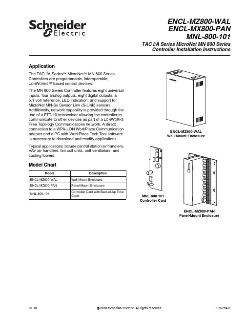
ApplicationThe TAC I/A Series™ MicroNet™ MN800 Series Controllers are programmable, interoperable,L ON W ORKS™ based control devices.The MN800 Series Controller features eight universal inputs, four analog outputs, eight digital outputs, a 5.1volt reference, LED indication, and support for MicroNet MN-Sx Sensor Link (S-Link) sensors. Additionally, network capability is provided through the use of a FTT-10 transceiver allowing the controller to communicate to other devices as part of a L ON W ORKS Free Topology Communications network. A direct connection to a WPA-LON WorkPlace Communication adapter and a PC with WorkPlace Tech Tool software is necessary to download and modify applications. Typical applications include central station air handlers, VAV air handlers, fan coil units, unit ventilators, and cooling towers.Model ChartModel DescriptionENCL-MZ800-WAL Wall-Mount EnclosureENCL-MZ800-PAN Panel-Mount EnclosureMNL-800-101Controller Card with Backed-up TimeClockENCL-MZ800-WALENCL-MX800-PANMNL-800-101TAC I/A SeriesMicroNet MN800 SeriesController Installation InstructionsENCL-MZ800-WALWall-Mount EnclosureMNL-800-101Controller CardENCL-MZ800-PANPanel-Mount Enclosure08-13© 2013 Schneider Electric. All rights reserved.F-26724-62© 2013 Schneider Electric. All rights reserved.F-26724-6Applicable DocumentationInstallationInspectionInspect carton for damage. If damaged, notify carrier immediately. Inspect controllers for damage. Return damaged products.Requirements (These items not provided):•Installer must be qualified, experienced technician.•Job wiring diagrams•Tools–Drill and bits for panel mounting screws–Digital Volt-ohm meter (DVM)–Static protection wrist strap•Class 1 or Class 2 power transformer supplying a nominal 24 Vac (20.4 to 30 Vac) witha minimum rating of 20 VA, 50/60 Hz per controller plus Digital Output (DO) loads (ifsame transformer is used). In European Community, transformer must conform to localstandards.•Terminators–One LON-TERM1 terminator required for free topologies–Two LON-TERM2 terminators required for bus topologiesPrecautions Warning:•Electrical shock hazard! Disconnect power before installing or removing the cover.•Follow Static precautions when installing this equipment.•Use copper conductors that are suitable for 167°F (75°C)•Make all connections according to electrical wiring diagram, national and localelectrical codes.F-Number DescriptionAudience Purpose F-26277TAC I/A SeriesMicronetMN-SX Series SensorsGeneral Instructions–Application Engineers –Installers –Service Personnel –Start-up Technicians Provides step-by-step installation and checkout procedures for TAC I/A Series MicroNet MN-SX Series Sensors. Also contains instructions for sensor operation.F-26303TAC I/A SeriesMicroNetSystem Overview –Application Engineers –Installers –Start-up Technicians –Service Personnel Provides an overview of the TAC I/A Series MicroNet System. It includes brief descriptions of the hardware and software components, and how they may be combined to create MicroNet networks and stand-alone systems.F-26580WorkPlace Tech Tool Engineering Guide –Application Engineers –Installers –Service Personnel –Start-up Technicians Provides engineering and technical information for applying and using all aspects of WorkPlace Tech Tool.F-26507TAC I/A Series MicroNet System Engineering Guide –Application Engineers –Installers –Service Personnel –Start-up Technicians Provides engineering and technical information to assist in designing a complete TAC MicroNet controller system using different architectures, components, and software.F-26304WorkPlace Tech Tool User’s Guide–Application Engineers –Installers –Service Personnel –Start-up Technicians Provides step-by-step instructions for using WorkPlace Tech Tool.F-26363EN-206 Guidelines forPowering Multiple Full-Wave and Half-WaveRectifier Devices froma CommonTransformer –Application Engineers –Installers –Service Personnel Offers guidelines for avoiding equipment damage associated with improperly wiring devices of varying rectifier types. Contains instructions for identifying device rectifier type, guidelines for correctly powering devices of varying rectifier types, and examples illustrating proper power wiring techniques.Static PrecautionsStatic charges damage electrical components. The microprocessor and associated circuitryare extremely sensitive to static discharge. Use the following precautions when installing,servicing, or operating the system.•Work in a static-free area•Discharge static electricity by touching a known, securely grounded object.•Use a wrist strap connected to earth ground when handling the controller’s printedcircuit board.Federal Communications Commission (FCC)This equipment has been tested and found to comply with the limits for a Class B digitaldevice, pursuant to Part 15 of the FCC Rules. These limits are designed to providereasonable protection against harmful interference in residential installations. Thisequipment generates, uses, and can radiate radio frequency energy and may cause harmfulinterference if not installed and used in accordance with the instructions. Even wheninstructions are followed, there is no guarantee that interference will not occur in a particularinstallation. If this equipment causes harmful interference to radio or television reception--which can be determined by turning the equipment off and on-- the user is encouraged to tryto correct the interference by one or more of the following measures:•Reorient or relocate the receiving antenna.•Increase the separation between the equipment and receiver.•Connect the equipment to an outlet on a circuit different from that to which the receiveris connected.•Consult the dealer or an experienced radio/television technician for help.Canadian Department of Communications (DOC)This class B digital apparatus meets all requirements of the Canadian Interference-CausingEquipment Regulations.Cet appareil numerique de la classe [B] respecte toutes les exigences du Reglement sur lematerial broilleur du Canada.European Community DirectivesThis equipment meets all requirements of European Community Directives for Low Voltage(72/23/EEC) and Electromagnetic Compatibility (89/336/EEC).Caution:This is a class A product. In a domestic environment this product may causeradio interference in which case the user may be required to take adequate measures.Location These controllers are suitable for indoor use only.Caution:•Avoid locations where excessive moisture, corrosive fumes, vibration, or explosivevapors are present.•Avoid electrical noise interference. Do not install near large contactors, electricalmachinery, or welding equipment.•Locate where ambient temperatures do not exceed 140°F (60°C) or fall below -40°F(-40°C) and relative humidity does not exceed 95% or fall below 5%, non-condensing.Mounting Panel Mount Installation (ENCL-MZ800-PAN)ENCL-MZ800-PAN uses a sheet metal mounting plate. The enclosure has four mountingholes. Mount in a vertical position as shown in Figure-1. Allow access for wiring and removalof the assembly for service.Use the mounting holes provided.F-26724-6© 2013 Schneider Electric. All rights reserved.34© 2013 Schneider Electric. All rights reserved.F-26724-6Caution:•Drilling holes in the controller or mounting plate voids warranty.•Do not drill into mounting plate or any other part of controller. Metal chips and other debris may short-circuit electronic components.1.Select mounting ing four #8 pan head screws, mount base of controller to a panel.3.Wire controller (See Wiring section).4.After wiring, remove aluminum cover plate.5.Remove protective tape from edge of card connector.6.Install printed circuit board. (See MNL-800-101 Printed Circuit Board Installation.)Figure-1ENCL-MZ800-PAN Panel Mounting Dimensions.Wall Mount Installation (ENCL-MZ800-WAL)ENCL-MZ800-WAL use sa sheet metal enclosure. The enclosure has four mounting holes and eight combination knockouts (1/2" to 3/4") (Figure-2). Mount in a vertical position and allow access for wiring and removal of the printed circuit board assembly for e the mounting holes and knockouts provided.Caution:•Drilling holes in the controller or enclosure voids the warranty.•Do not drill into the enclosure or any other part of the controller. Metal chips and other debris may short-circuit electronic components.1.Select mounting location.2.Remove ing four #8 pan head screws, mount controller.4.Wire controller (see Wiring section).5.Remove protective tape from edge of card connector.6.Install printed circuit board. (See MNL-800-101 Printed Circuit Board Installation.)F-26724-6© 2013 Schneider Electric. All rights reserved.5Figure-2ENCL-MZ800-WAL Wall Mounting Dimensions.WiringSee Figure-3 for terminal connections.A power transformer supplying a nominal 24 Vac (20.4 to 30 Vac) with a minimum rating of20 VA, 50/60 Hz per controller is required. The supply to the transformer must be providedwith a circuit breaker or disconnect. Use class 1 wiring for the transformer wiring.Figure-3Terminal Connections.6© 2013 Schneider Electric. All rights reserved.F-26724-6Caution:•Do not install the low voltage input/output wiring (UI/AO) in the same conduit with power or DO wiring with a potential greater than 30 Vac rms.•Use shielded cable if the low voltage input/output wiring (UI/AO) is installed in the same conduit with power or DO wiring with a potential less than 30 Vac rms.•Do not use the inside of the sensor enclosure or the wiring compartments of the MN 800 as a junction box for other control circuits.Although not required, shielded cable may used for AI, DI, and AO wiring. Fold the foil shield back over the cable jacket and compress it at the point of entry or exit of each controller. Use a sheathed cable connector in the knockout at the point of entry or exit.After the entire system has been installed and wired, verify wiring with the use of a DVM to insure against wiring errors, overvoltage, or short circuits.MNL-800-101 Printed Circuit Board Installation Mount the controller and complete wiring before installing the printed circuit board.1.Verify power is OFF .2.Follow the Static Precautions.3.Remove enclosure cover.Caution:Do not pull or push on the circuit board components when installing or removing the printed circuit board. Doing so may result in damage to the circuit board assembly.4.Remove and discard protected shipping tape from card slot.5.Slide printed circuit board into place (Figure-4).6.Replace enclosure cover.Figure-4Printed Circuit Board munications Wiring Caution:•Communication wire pairs must be dedicated to S-LK and MicroNet L ON W ORKS network (LON) communications. They cannot be part of an active, bundled telephone trunk.•Shielded cable is not required for S-LK or LON wiring.•If the cable is installed in areas of high RFI/EMI, the cable must be in conduit.•If shielded wire is used, the shield must be connected to earth ground at one end only by a 470K ohm 1/4 watt resistor. Shield must be continuous from one end of the trunk to the other.Communications wiring includes a connection between the controller and a TAC I/A SeriesMicroNet Sensor via the S-LK and a connection between the controller and the MicroNetL ON W ORKS Network (LON). An optional LON connection between the controller and oneTAC I/A Series MicroNet Sensor is also possible.Sensor Link (S-LK) WiringS-LK wiring powers and enables the MN-SX Sensor. The S-LK needs at least 24 gage(0.51mm), twisted pair, voice grade telephone wire. The capacitance between conductorscannot be more than 32 pF per foot (0.3m). If shielded cable is used, the capacitancebetween any one conductor and the others, connected to the shield, cannot be more than60 pF per foot (0.3m). Maximum wire length is 200 ft. (61m).Note:•Controller supports one TAC I/A Series MicroNet Sensor (MN-SX).•S-LK wiring is polarity insensitive.•If conduit is used between a TAC I/A Series Sensor and a controller, the MicroNetL ON W ORKS network and S-LK wiring can be in the same conduit.•S-LK wiring (not LON wiring) can be in the same conduit with UI, AO, and DI wiring.MicroNet L ON W ORKS Network (LON) WiringA Category 4, twisted-pair (two conductors) cable may be used for LON connection betweencontrollers and between a controller and an MN-SX sensor. LON wiring is polarityinsensitive.Caution:Do not mix with UI, AO, DI or DO types of wiring. If conduit is used between aTAC I/A Series Sensor and a controller, LON wiring and S-LK wiring can be in the sameconduit.MN 800 controllers use L ON W ORKS Free Topology Transceiver (FTT-10) and supportpolarity insensitive bus (daisy-chain) and free (all combinations of star, tee, and loop) wiringtopologies. A maximum of 62 nodes can be connected per segment.See TAC I/A Series MicroNet System Engineering Guide, F-26507 to design a MicroNetL ON W ORKS FTT-10 network, including recommended topologies and approved cable types. CheckoutStand-alone Controller1.Verify controlled devices are not powered or are in a controlled manual condition.2.Apply power to MN 800 controller.3.Check LED operation using Table-1.Table-1LED IndicationsLED Operation StatusGreenON Normally ON indicating controller is powered and not actively transmitting data on the LON. Flashes OFF Flashes OFF while actively transmitting data on the LON.AmberOFF Normally OFF unless actively receiving data from the LON. Flashes ON Flashes ON while actively receiving data from the LON.RedOFF(Neuron - normal communications) Indicates the Neuron is operating properly allowing normalcommunications to and from the HVAC application.OFF(Neuron - Off line) Neuron responds to network management messages only. In this state,communication to and from the HVAC application is not possible. To Correct, place the Neuron on-line by downloading an application using WP Tech or configure using a third party managementtool.BlinkingThe service LED blinks at 0.5 Hz rate (1 second ON, 1 second OFF) to indicate that the Neuron isunconfigured (i.e. communications parameters not loaded). Corrective action: Configure theNeuron by downloading an application using the Work Place Technician’s Tool or configure theneuron using a third party management tool.ON Indicates Neuron is not operating properly. Replace controller.F-26724-6© 2013 Schneider Electric. All rights reserved.7Distributed, manufactured, and sold by Schneider Electric. I/A Series trademarks are owned by Invensys Systems, Inc. and are used on this product under master license from Invensys. Invensys does not manufacture this product or provide any product warranty or support. For service, support, and warranty information, contact Schneider Electric at 1-888-444-1311.All brand names, trademarks and registered trademarks are the property of their respective owners. Information contained within this document is subject to change without notice. Schneider Electric 1354 Clifford Avenue, P.O. Box 2940, Loves Park, IL 61132-2940, USA 1-888-444-1311 /buildingsF-26724-6August 2013 ptm © 2013 S c h n e i d e r E l e c t r i c . A l l r i g h t s r e s e r v e d .4.Power down MN 800 controller if the programming will be done later, or program using WorkPlace Tech.Figure-5LED Indicators.Service Components within the MN 800 are not field repairable. The printed circuit board may bereplaced, if necessary. (Follow the procedure described earlier in the Printed Circuit BoardInstallation section.) Consult your local Schneider Electric office for additional servicedetails.Heartbeat (Green LED)Blinking (Normal operation) The heartbeat LED blinks at 0.5 second ON, 0.5 second OFF to indicatecontroller is operating properly.Wink Mode Wink mode provides a visual means for identifying the controller using WP Tech or third partymanagement tool. During wink, the heartbeat LED blinks as follows:With revision 1.x firmware: 2 seconds ON, 0.5 seconds OFF; cycles five times for a total of 12.5seconds of wink time.With revision 2.x (or later) firmware: 3 seconds ON, 1 second OFF; cycles three times for total of 12seconds wink time.Diagnostic Blink (RAM/ROM Failure) The heartbeat LED repeats a pattern of 2 quick flashes followed by pause. Tocorrect, turn power OFF then ON. Replace controller if necessary.Diagnostic Blink (ROM Failure) The heartbeat LED repeats a pattern of three quick flashes followed by a pause. Tocorrect, turn power OFF then ON. Replace controller if necessary.Diagnostic Blink (RAM Failure) The heartbeat LED repeats a pattern of four quick flashes followed by a pause. Tocorrect, turn power OFF then ON. Replace controller if necessary.OFFIndicates controller is not operating properly. Check power. Replace controller if necessary.Table-1LED IndicationsLED OperationStatus。
安迪瓦尔电子控制模块产品说明书

CSPID1S0
Single loop module, solid state outputs
CSPID1SA
Single loop module, solid state out. Analog output
CSPID1SM
Single loop module, solid state, heater current input
Model CSSG
Strain Gage PID Control Module l Performs Reverse, Direct,
or Reverse/Direct Control l Input Accepts 20 mV, 33 mV,
or 200 mV Strain Gage Signals l Secondary Input for Calculation
Increase Overall Reading Rate l Programmable Slope and Offset
Correction to Remove Sensor Error l Ideal for Data-Acquisition
Applications l Auto Addressing Minimizes
of Difference, Sum, Average, etc. l Selectable 5 or 10V Excitation l Three Alarm Outputs per Module l Fully Isolated Design Provides
Reliable Operation l PID Control With Reduced
to Increase Overall Reading Rate l Ideal for Data-Acquisition
- 1、下载文档前请自行甄别文档内容的完整性,平台不提供额外的编辑、内容补充、找答案等附加服务。
- 2、"仅部分预览"的文档,不可在线预览部分如存在完整性等问题,可反馈申请退款(可完整预览的文档不适用该条件!)。
- 3、如文档侵犯您的权益,请联系客服反馈,我们会尽快为您处理(人工客服工作时间:9:00-18:30)。
(中美合资)深圳威玛网电科技有限公司
WM-780Ⅰ系列可视楼层控制型系统单元器件
安
装
说
明
书
(第三代版本)
产品系统介绍
本产品为总线制楼宇可视楼层控制型对讲系统单元器件,具有功能强大、性能稳定、安装、调试方便,为一体化的智能楼宇对讲系统。
本系统所采用的芯片是台湾、美国原装进口芯片,可靠性强、抗干扰能力强、可在高低温条件下使用等优势。
产品功能介绍
1、可视室内手提分机
《具有接听、监视、开锁、双向通话功能》
2、可视室内免提分机
《具有接听、监视、开锁、双向通话,免提功能》
3、可视楼层控制器
《具有数据、语音、视频转换、户户隔离、加电源接口选择功能》
目录
WM-780Ⅰ系列控制器型可视室内手提分机 (3)
WM-780Ⅰ系列控制器型可视室内免提分机 (4)
WM-780Ⅰ系列可视楼层控制器 (5)
WM-780Ⅰ系列控制器型器件接入对讲系统图 (7)
说明书阅读(打印)指南:
请对照所订购之分机型号,找到相应目录内容,参看此部分内容。
同时请务必参看“WM-780Ⅰ系列可视楼层控制器”和“WM-780Ⅰ系列控制器型器件接入对讲系统图”内容。
WM-780Ⅰ系列控制器型可视室内手提分机
简要介绍
产品型号:
WM-780 I PC1 /PC2/PC3
兼容型号:
WM-780 I PD1/PD2/PD3,WM-780 I PE1/PE2/PE3,WM-780 I PG1/PG2/PG3,WM-780 I PL1 /PL2等
主要特点:
(1)工作电压:DC18V、工作电流:1A
(2)分机待机无功耗,不用编码
(3)线路自动保护
(4)视频亮度,对比度可调
(5)黑白可视4寸屏,彩色可视3.5寸、4寸屏
外观图:如右
安装接线
壁挂式安装,安装位置一般都安装在进门的客厅墙面
上,以显示屏中心为准,建议距地1.45-1.55米为佳。
使用
RVV4*0.5+SYV75-3-96视频线(国标)。
通过联接WM-780 I系列可视不联网楼层控制器接入系统
使用。
使用说明
(1)来电呼叫对讲
单元主机、管理中心机、小区入口主机等呼叫,本机发出来电铃音,同时显示屏打开,提起听话筒可接听电话,通话中按下“开锁”键开启主叫主机所控制的电锁。
通话结束话筒挂上则可。
如没有手动操作,系统将在1分中后自动挂机。
(2)监视单元主机
待机状态下,拿起听筒即可监视单元主机,显示屏上看见主机前的景象,监听主机;挂机,结束监视过程。
没有手动挂机,系统将在30秒钟后自动挂机。
(3)呼叫管理中心机
拿起听筒按“呼叫”键则可呼叫管理中心机,管理中心机响应接听可双向通话,通话结束话筒挂上则可。
如没有手动操作,系统将在1分中后自动挂机。
典型故障处理
(1)摘机不能监视:检查楼层控制器是否供电,线路和本机是否正常。
(2)本机不振铃:换到好的房间试下,如还是不行;更换分机。
(3)本机不能开锁:开锁按键是否按下。
(4)本机不能通话:楼层控制器到本机语音线是否有问题,本机是否正常。
(5)不能摘机通话:把本机换到好的房间试下,如正常表示线路问题,不正常表示本机问题;更换即可。
WM-780Ⅰ系列控制器型可视室内免提分机
简要介绍
产品型号:
WM-780ⅠPM1/PM2/PM3
兼容型号:
WM-780ⅠPN1/PN2/PN3、WM-780IPP1/PP2/PP3、WM-780IPV1/PV2/PV3、WM-780ⅠPT3、WM-780ⅠPT2、WM-780ⅠPT4、WM-780ⅠPT6、WM-780ⅠPT8、WM-780ⅠPX2/PX3等
主要特点:
(1)工作电压:DC18V,电流:1A
(2)分机待机无功耗,不用编码
(3)线路自动保护
(4)操作提示音,通话保密性高
(5)黑白可视4寸屏,彩色可视3.5寸、4寸、7寸屏
外观图:如右
安装接线
壁挂式安装,安装位置一般都安装在进门的客厅墙面上,以显示
屏中心为准,建议距地1.45-1.55米为佳。
使用
RVV4*0.5+SYV75-3-96视频线(国标)。
通过联接WM-780Ⅰ系列可视楼层控制器接入系统使用。
使用说明
(1)来电呼叫对讲
单元主机、小区入口主机、管理中心机呼叫本机,发出来电铃音,同时显示屏打开,按下“通话”键接听通话;通话中按下“开锁”键,开启主叫主机所控制的电锁;再次按下“通话”键结束通话。
没有手动操作挂机,系统将在1分钟后自动挂机。
(2)监视单元主机
待机状态下,按下“监视”键即可可看见主机前的景象;再按下“监视”键,结束监视过程。
如没有手动操作,系统将在30秒钟后结束监视过程。
(3)呼叫管理中心机
待机状态下,按“呼叫”键可呼叫管理中心机,管理中心机有响应可双向通话。
按下“通话”键结束通话。
没有手动操作挂机,系统将在1分钟后自动挂机。
典型故障处理
(1)不能监视:检查楼层控制器是否供电,线路和本机是否正常。
(2)不振铃:检查振铃电位器是否关闭,或换到好的房间试下,如还是不行;更换分机。
(3)不能开锁:开锁按键是否按下。
(4)不能通话:楼层控制器到本机语音线是否有问题,本机是否正常。
把本机换到好的房间试下,如正常表示线路问题,不正常表示本机问题;更换即可。
WM-780Ⅰ系列可视楼层控制器
简要介绍
产品型号:WM -780 I LKQ4
主要特点:
(1)工作电压:DC18V,工作电流:3A
(2)音视频故障户户隔离,电源故障户户隔离,数据故障户户隔离;
(3)音视频信号驱动、放大;楼层数据解码;数据放大切换;
控制器内部电路板图:
POWER电源接口,J4电源选择,INPUT总线入,OUTPUT总线出,F01、F02、F03、F04分机接口,JP1层号设置,JP2房号设置。
安装接线
安装位置一般都安装在弱电井内(或楼梯间)的分线处,高度建议距地1.35-1.45米或距顶0.25米为佳。
总线及分机接口线使用RVV4*0.5+SYV75-3-96视频线(国标)。
电源线电源线RVV2*1.0(国标)。
通过联接WM-780Ⅰ系列控制器型可视室内分机及可视主机分机总线接口接入系统使用。
楼层控制器型系统安装,供电建议使用输出直流18V3A的电源,如型号: WM –
P18V3A I等。
楼层控制器到用户分机用线(进户线)长度在40米内的情况下,每超过5个楼层控制器(或20台用户分机),须加一台系统电源。
同时楼层控制器采用主机电源供电情况也不得超过5个楼层控制器(或20台用户分机)。
使用说明
供电方式设置:
出厂设置默认本机由总线提供电源,电源选择J4的2 3脚接通。
电源选择J4的1 2脚接通,本机由附加电源箱提供电源。
房号地址设置:
操作前请先断电,操作完成再通上电源。
层号十位数层号个位数房号个位房号十位N(跨楼层设置)
JP1:1 2 4 8 1 2 4 8 JP2: 1 2 4 8 16 N
1)层号十位数:JP1插针数字:1 2 4 8对应数值为1、2、4、8
(如编:3;短路插针插在1和2上,相加得出)。
2)层号个位数: JP1插针数字:1 2 4 8 对应数值为1、2、4、8
(如编:5 ,插针插在1和4上相加得5。
)
3)房号个位数:JP2插针数字:1对应数值为4
(如编:8;插针插在1上;再把室内分机插在F04接口上)
4)房号十位数:JP2插针数字:2 4 8 16对应数值为8、16、32、64
(如编:25;插针插在2和4上相加得出25;再把室内分机插在F01接口上)
5)跨楼层设置:JP2插针N默认不插,插上F03、F04的层号加1,同时F03为房号01,F04为房号02,F01、F02不变。
用于一梯一户或一梯两户、两层共用一个楼层控制器的情况。
例1:房号设置为“0812”(08表示层号、12表示房号)
(1)将短路插针插在楼层号个位数8;(对应数值为8)
(2)把短路插针插针房号十位数2(对应数值为8)上,再把室内分机插在F04上,其余均为不插;此时房间号就为“0812”。
例2:跨楼层设置房号“0302”(03表示层号、02表示房号)
首先用短路插针把JP2中最后一个插针“N”插上
(1)将短路插针插在楼层号个位数2上;(对应数值2,自动增加1变为3)
(2)把室内分机插在F04上,其余均为不插;此时房间号就为“0302”。
典型故障处理
(1)本机电源指示灯不亮:请检查6芯总线是否插上或插好,短路插插针是否插在2 和3上。
(2)本机地址码设置不了:设置时是否断电操作,插针有无插好,室内分机有无插上或插好;本机是否正常。
(3)分机不能振铃:本机有问题(前提时室内分机和线路正常的情况下)。
(4)短路了起不了保护作用:本机有问题,需要更换。
WM-780Ⅰ系列控制器型器件接入对讲系统图。