单兵背包天线(XFDTD案例)
某型卫星通信单兵背负站电磁兼容设计和改进

第24期2019年12月No.24December,2019随着科学技术的进步,卫星通信技术在军事领域得到了广泛应用。
小型化的卫星通信单兵背负站给野外作战提供了重要手段。
但在战场,背负站所处的电磁环境日益复杂,降低设备辐射发射对通信质量的提高起着重要作用。
本文旨在针对某型卫星通信单兵背负站的电磁兼容问题展开讨论,通过试验和设计改进,以期提高产品的电磁兼容性指标。
1 设备描述卫星通信单兵背负站(以下简称背负站)主要应用于野外作战通信,由手持操作终端、通信主机和卫星通信天线3部分组成。
手持操作终端功耗较小,提供简便的人机交互数据设置和查询功能;卫星通信天线为无源天线,在背负站架起时,实时接收和发射信号;通信主机在入网后,与友方其他通信站建立卫星通信链路,提供话音和数据功能。
根据研制要求,规定背负站满足标准GJB 151B-2013《军用设备和分系统电磁发射和敏感度要求和测量》,产品电磁发射类测试项目有CE102和RE102,各项目的测试目的如下所述。
CE102项目测试频段10 kHz ~10 MHz ,为了控制背负站工作时通过电源线以传导或辐射的方式对外造成干扰。
在较低频段,设备充电时会通过电源线向公共电网注入传导干扰;在较高频段,干扰会经电源线向外造成的辐射。
电源电路是产生传导发射超标的重要根源,同样也是造成电磁辐射发射的因素之一。
RE102项目测试频段2 MHz ~18 GHz ,为了控制背负站工作时通过壳体、电缆向外辐射电场,防止其对灵敏接收设备产生干扰,如设备孔、缝隙、显示屏和按键等,对外形成辐射干扰。
干扰的频率不仅有电源工作频率、晶振等信号的主频、倍频,更是各类信号的谐波。
抑制辐射发射干扰,滤波、接地和屏蔽是常见的设计手段[1]。
2 测试数据分析为了提高背负站的电磁兼容性,降低设备的辐射发射电平,对于RE102超标问题,从电磁干扰三要素(干扰源、耦合路径和敏感源)理论出发,分析和定位引起超标的电磁干扰源,辐射发射耦合路径着手。
运用XFdtd设计穿戴式装置可弯曲双频MIMO天线

运用XFdtd设计穿戴式智慧装置之双频MIMO天线简介本案例演示一个纺织品材料制作,用于穿戴式装置的双频天线,基础天线本身是个矩形的贴片天线,内部是纺织品,外部由带状的导电胶带包覆,由于天线本身有弹性,故同时建立平放和弯曲两种状态的模型以便于了解形状改变对于天线性能的影响,也进一步做了关于人体的SAR 值计算并且得到合格的结果,之后将这些贴片天线组成阵列,并且改变各种配置进行MIMO应用的仿真演示。
模型设计与仿真平放的单体天线第一阶段先建立平放的单体贴片天线模型,俯视和45度侧视如下图的1a以及1b,天线本身为矩型,里面有一层3mm厚度的毛毡面料作为基板,外面用一层经过特殊处理的并且很薄的导电胶带覆盖使其适合作为天线单元在阵列中使用。
图1 : 俯视图(左,1a),45度角侧视图(右,1b)用XFdtd仿真这个最基本的天线模型,透过一个宽带的仿真,在2.5GHz和5GHz得到满意的return loss(图二),而图三则是在多个不同频点贴片表面的稳态磁场,分别是图3a为2.45GHz,3b为5.2GHz,3c为5.5GH,3d为5.8GHz,图四则是三维增益场型,在2.45GHz时为3.4 dBi,5.5GHz为6.7dBi。
图二: 仿真的return loss结果显示单一贴片天线在2.5 GHz以及5.4 GHz到5.8 GHz的区域有明显的null,并且在高频段有较佳的操作空间。
图三: 不同频点的稳态磁场分布3a(左上)为2.45GHz,3b (右上) 5.2GHz,3c(左下)5.5 GHz,3d(右下)5.8 GHz。
图四: 不同频点的增益场型,4a (左)2.45 GHz,4b(右) 5.5 GHz。
透过仿真了解天线的基本特性后,进一步计算SAR值,将贴片天线置于由皮肤,脂肪,以及肌肉构成的多层phantom上5mm处进行仿真(图五),透过仿真可知在当输入功率为0.5瓦时1公克平均SAR(1-gram averaged SAR)值的峰值在2.45GHz时为0.113W/kg,5.5 GH 时为0.18W/kg,两者均低于工业标准允许的上限值,同样的输入功率下,10公克平均SAR 值为2.45GHz时为0.058W/kg,5.5GHz 时为0.082W/kg,也低于工业标准允许的上限值,图六为在不同频点的SAR值分布。
Codan2110背负式短波电台战术天线

Codan2110背负式短波电台战术天线
柯顿公司提供一系列的天线解决方案,用以适应不同的移动需求、快速部署和长/短程通讯。
(1)鞭天线:
电台内置天线调谐器,鞭天线适合近距离通讯。
天线轻质、可折叠、可快速安装。
天
线长度1.5米和3米。
1.5米天线适合行进中通讯,3米天线有更好的通讯性能。
(2)斜拉天线:
频率1.6MHz—30MHz,长度为10米的战术斜拉天线,能提供比短鞭天线更优越的通讯性能。
设计用于短距离或中距离通讯。
斜拉天线很轻,包括kevlar增强线缆、适配器(连接天调)、缠绕着绳子的卷轴。
*
(3)宽带双极天线:
包括缠绕着绳子的卷轴、kevlar增强线缆、适配器、平衡转换器、端子、地线、地钉等。
宽带天线适合于多频率操作,包括ALE。
双极天线在单一频率通讯性能好。
双极天线通过调节使用的天线长度,调谐到所需频率。
Codan2110电台可显示给定频率所需的双极天线长度。
美化天线产品及案例

美化天线产品及案例本文介绍了几种常见的普通基站类天线产品,包括一体化集束天线、排气管型天线、集束隐蔽外罩、半自动组合型、排风管型、烟囱型和变色龙型。
其中,一体化集束天线适合于新建站址,具有体积小、重量轻、结构强度高等特点;排气管型天线直径200mm,高度2500-4000mm,隐蔽性强,安装方便;集束隐蔽外罩可同时安装1~3副天线,适合于公共场所和居民住宅小区等;半自动组合型可内置三扇区天线,通过机械传动开闭,方便维护;排风管型和烟囱型适合于商务区或住宅区楼顶,可以直接安装在楼顶;变色龙型则具有外形美观、颜色可变等特点。
这些天线产品在不同的场景下可以灵活选配,满足不同站点的需求。
XXX-shaped concealed antenna (cover) is wall-mounted and can be hung in different ns on the building wall according to needs。
The cover is equipped with a unique hook device for easy XXX。
The surface of the cover can be treated to match the n of the installed wall。
making it XXX.The square column type antenna is hidden inside the square column-shaped concealed cover。
which can be XXX on the building roof according to the overall style of the building。
The cover has a XXX。
The surface texture of the cover can be processed to match the overall n style of the building。
消防单兵惯性导航系统的设计
消防单兵惯性导航系统的设计消防单兵护卫惯性导航系统是一种智能化的产品,可准确计算和预测消防员在紧急情况下的位置、速度和方向等相关信息,以帮助消防员有效地执行任务。
随着科技的不断发展,这种智能化的装备已经被广泛应用于消防工作中,成为了消防员们必不可少的装备之一。
一、消防单兵惯性导航系统简介消防单兵惯性导航系统是一种基于微小惯性导航仪和全球卫星定位系统(GPS)技术的装备,可以记录并显示消防员在复杂环境中的运动轨迹和位置信息,实现更加高效和安全的消防应急响应。
该装备包括一个小型传感器、一个微处理器和一个显示器。
传感器可以接收来自消防员身上的运动信号,微处理器则根据这些信号计算出消防员的位置和方向,将这些信息传输到显示器上,帮助消防员更好地控制局面。
二、消防单兵惯性导航系统的作用1. 帮助消防员快速找到火场的位置在高层建筑内,火灾往往很难被发现。
消防员在火场搜索时很难辨别方向和位置,会引起迷惑和增加救援时间。
如果将惯性导航系统与空间地图结合起来,消防员可以在大楼中快速找到火灾的位置,合理指挥人员救援。
2. 帮助消防员避免误入危险区域消防工作中经常涉及到火势、瓦斯等因素,消防员可能会误入危险区域而受到风险威胁。
狭隘而不稳定的空间,如隧道、地下停车场等,极易使消防员迷失方向。
使用消防单兵惯性导航系统可以在实时监测火势和烟雾分布的同时,避免消防员误入危险区域。
3. 提高作业效率和安全在救火过程中,消防员需要进行一系列操作和行动,如高空落体、投射水流和进行上下爬升等。
在这些任务中,有时受到环境和情况的制约,消防员往往需要快速作出决策和动作,用最短的时间实现任务。
消防单兵惯性导航系统的使用可以大大提高消防员的行动效能和水平,实现更真实、稳定、准确的运动控制。
三、消防单兵惯性导航系统在实际工作中的应用1. 北京首都机场消防局该机构在母机场范围内实行24小时动态监控和安全管控,引入惯性导航系统可以对监测区域进行定点摆放,对应不同消防类别、不同方向的立点布控,进一步提升了监测及防灭火效果。
单兵背包雷达
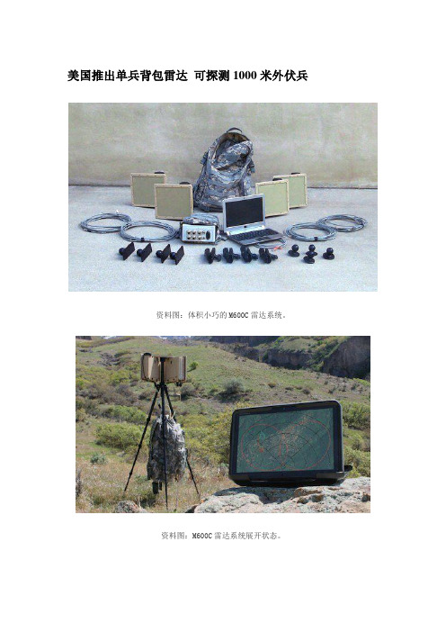
美国推出单兵背包雷达可探测1000米外伏兵资料图:体积小巧的M600C雷达系统。
资料图:M600C雷达系统展开状态。
据美国福克斯新闻网近日报道,美国SpotterRF公司日前开发出一种只有一个背包大小的单兵雷达系统。
该系统能准确探测到埋伏在1000米范围以内的敌人和车辆并及时发出警报,非常适用于对关键地点的防御和警戒。
该装备具有体积小、重量轻、能耗低、适应力强、简单易用的特点。
整套装备包括一套M600C雷达、一个网络集线器、一个安卓平板电脑、一个三脚架、一些线缆和一个背包,重量不到20磅(约9公斤),一般士兵在30分钟内就能学会操作。
这款名为SpotterRFM600的雷达传感系统的主体只有一个笔记本电脑大小,战斗人员能轻松地将其带到任何位置,整机没有移动部件,只需3分钟就能完成安装架设。
它不但重量轻,耗电量也极低,其功率只有10瓦,这意味着士兵们完全不必携带笨重的电池。
无论能见度和天气条件如何,SpotterRFM60都能够准确地检测到入侵之敌。
它利用自身的内置数字罗盘和全球定位系统来确定装置的位置,并能够方便地与谷歌地球、Falconview等位置软件进行通讯,将敌人的位置显示在地图上。
增加附加装置后它还能自动实现360度的覆盖。
在界面上,它提供了一个基于Web的安全界面,兼容智能手机、安卓平板电脑和普通个人电脑。
SpotterRF公司首席执行官洛根·哈里斯说,这种装备增强了士兵对战场态势的感知能力,能大幅减少精锐部队因遭伏击而导致的伤亡。
英国Plextek公司展出B400单兵携带式雷达[据英国《简氏防务》2009年2月24日报道] Plextek公司展出了两部山地单兵携带式的雷达和一个性能显示装置。
公司成产的先进的技术产品为抵御来自常规和非对称/恐怖分子威胁提供保护,其中英国陆军就是Blighter B400系列雷达的用户。
体积更小些的B200和B400系列单兵携带式雷达能够提供90°方位角模块扫描,并且可以通过附加模块实现360°扫描。
单兵背负雷达轻质天线结构设计

同时为 了达 到 快速 装 配 的 目的 , 计 了定 位机 设 构 和 快速 连 接 机构 , 线组 装 时先 利 用定 位 机 构确 天
天 线 分成 三 块 , 装 定位 的基 准 是 天线 整 体 精 拼 度 的有效 保证 , 了保 证天 线 拼装后 的整体精 度 , 为 天 线三 块反 射 面均设 计 校 正 标 记 点 , 为 反 射 面 拼装 作 后 的精度 校测 基 准 , 同时标 记 天线 设 计 基 准 点 作 为
复合材料轻质 的特点 , 对天线进行合理分块设计 , 解决质量 、 尺寸 、 刚度 匹配 的技术难题 , 设计 出满足要求 的轻 质天 线 , 正常工况 下最 大变形 为 0 2 m, 天线 .5m 复合材料最大层间剪切应力为 6 8 a .MP 。
关键词 轻质天线 ; 纤维 ; 碳 复合材料 ; 刚度
i .T e l g e omai n o n e n a . 5 t e h a e d f r t f tn a w s0 2 mm ,t e i tr mi ai n s e rf r e o o o i s6 8 a r o a h n e l n t h a o c fc mp st wa . MP . a o e
装匹配 带来 精度 影 响 问题 , 就 要 求 设计 天 线 时 必 这
须综合考虑天线骨架的质量 、 刚度 、 机械接 口、 构型
设 计 和材料设 计 的 匹配 问题 。
2 轻质天线结构设计
2 1 天线 分块 设计 .
为 了满 足 单 兵背 负 状态 技 术 要求 , 必须 对 天线
图 2 天线 拼装 基 准 示 意 图
进行分块设计 。该天线的 口径为 20 × 0 (l , 10 80 f i m)
便携式2米天线的结构设计(论文)

便携式2米天线的结构设计摘要:本课题着重阐述便携式2米天线结构特点和天线面图绘制的过程。
着重讲述了天线的工作原理和性能指标,介绍了一种结构新颖的便携式天线的设计,天线具有结构灵巧、重量性对同类天线的结构设计具有借鉴作用,并以创新的理念和实用性相结合设计出适应现代化信息的天线。
本设计运用了UG作图软件绘制图形,虽然以前课程没学习UG,但是UG也是一种绘制三维图强大的工具。
运用UG里面的各种操作命令能轻松而且快捷的绘制出你自己设计的各种零件图和装配图形。
它不但能节省设计者的时间,还能准确绘制出你所需要的零件图和装配图。
所以本文就以UG软件绘制天线天线面的结构进行说明和讲解。
关键词:2米天线;图绘制;结构新颖;创新的理念和实用性The Structure Design of a 2m Portable Antenna Abstract:This paper briefly introduces design feature of a 2m Portable Antenna and the process of pareto by parabola.And combining creative idea with practicability design aerial adapting to modernize. UG used the design drawing graphic mapping software, though not before learning courses UG, but UG is also a three-dimensional graph drawing powerful tool. UG which use a variety of command can easily and quickly map out the design your own map of various parts and assembly graphics. It will not only save time for designers, but also to map out the exact parts you need maps and assembly drawings. Therefore, this article on UG software to draw the structure of the antenna to the antenna face and explain .Key words:2m antenna; pareto; structure design目录第一章绪论 (1)1.1 课题的背景介绍……………..…………………………………… .11.2天线结构形式介绍 (2)1.3本课题主要研究内容 (3)1.4课题的意义与创新 (3)第二章总体方案设计 (3)2.1便携式2m天线的结构性能指标 (3)2.2 2m天线系统用途及设计总体要求 (4)2.3总体结构型式确立 (4)2.3.1便携式天线面的结构设计 (5)2.3.2天线座结构设计 (6)2.4天线面结构设计的方案比较与确定 (6)2.4.1方案比较 (6)2.4.2选择和评价 (6)第三章详细设计 (6)3.1设计软件介绍 (7)3.2设计思路 (7)3.3设计原则 (7)3.4零件的设计与部分零件的装配 (7)3.4.1中心盘零件的设计 (7)a底板和圆管零件的设计和装配 (8)b支耳零件的设计和装配 (9)c夹块零件的设计和装配 (11)d 中心柱零件的设计和装配 (12)e螺钉零件的设计 (13)f馈源支杆零件的设计和装配 (14)I天线面板零件的设计和装配 (15)3.5天线面的总体装配设计 (17)3.6天线面的总体二维装配设计 (22)第四章结语 (23)谢辞 (23)参考文献 (24)附录 (25)第一章绪论1.1 课题的背景介绍本天线主要应用于青藏高原。
- 1、下载文档前请自行甄别文档内容的完整性,平台不提供额外的编辑、内容补充、找答案等附加服务。
- 2、"仅部分预览"的文档,不可在线预览部分如存在完整性等问题,可反馈申请退款(可完整预览的文档不适用该条件!)。
- 3、如文档侵犯您的权益,请联系客服反馈,我们会尽快为您处理(人工客服工作时间:9:00-18:30)。
Computer Simulation Helps Design Wearable Antennas for Future Force WarriorFuture Force Warrior (FFW) is the Army’s flagship science and technology initiative to develop a lightweight, fully integrated combat system including weapon, head-to-toe protection and netted communications. A key part of FFW is providing conformal body worn antennas that have sufficient gain regardless of the warrior’s position. In designing a wearable antenna for the FFW program, MegaWave Corporation found that one of the greatest challenges was simulating the impact of the human body on the antenna’s performance. MegaWave engineers simulated these effects with finite difference time domain (FDTD) software that accurately models the effects of the body by representing it with a material having the properties of a saltwater body as described by Siwiak [Radiowave Propagation and Antennas for Personal Communication, Artech House, 1995]. The simulation determined impedance and radiation patterns of the initial design concepts. MegaWave engineers used the results to understand and improve their initial designs.MegaWave's engineering team brings over 80 years of combined experience in electromagnetic engineering, radio wave propagation and computational electromagnetics to the problem of designing antennas to meet the communications and end-user needs of the 21st century. The company’s military customers have included the Defense Advanced Research Projects Agency, the United States Army Communications and Electronics Command (CECOM), the U.S. Army Natick Labs, the United States Navy, and the United States Special Operations Command (SOCOM). The U.S. Army’s Communications and Electronics Research and Development Center (CERDEC) at Fort Monmouth enlisted MegaWave to assist with the development of new antennas for the FFW program which is intended to provide robust team communications during combat.Tough performance requirementsFFW antennas were required to provide approximately equal performance in all soldier positions, i.e. when the soldier is standing, and when the soldier is in the prone position. The wearable antennas also needed to be compatible with and fit on the FFW ensemble and not interfere with the soldier’s mobility. The antenna design was thus constrained by needing to be conformal to the FFW ensemble,to avoid any snagging hazard which might impede the soldier’s mobility and to operate in the presence of the warfighter’s ballistic armor plates.The tough performance requirements for the wearable antenna concept made simulation essential for quickly and inexpensively evaluating a wide range of designs. The challenge was simulating not just the performance of the antenna, but also the effects of the human body and the armor plates worn by the soldier. MegaWave engineers considered a number of modeling tools, but the requirement to include the human body and armor plates ruled out some approaches.FDTD simulation speeds antenna designMegaWave engineers decided to use XFdtd® software from Remcom Inc., State College, Pennsylvania, which incorporates a full-wave, three-dimensional solver based on the finite difference time domain (FDTD) method. “MegaWave was one of Remcom’s first customers for XFdtd. We originally selected this program because it offered superior price and performance to other alternatives available at that time,” said Glynda Benham, President of MegaWave. “We have seen the software make steady improvements over the years. Version 6 made particularly important advancements such as the ability to generate and display the antenna VSWR in addition to S parameters. Another major new feature is adaptive meshing which automatically generates a finer mesh in areas where more accuracy is needed while using a coarser mesh in other areas to reduce computational requirements.”Adaptive meshing capabilities reduce solution times while maintaining high levels of accuracy by automatically adjusting the mesh to provide more cells in areas with high transients and reducing cells in areas where there is less variation. In addition, the use of a distributed memory parallel computational code allows for cluster computers to be utilized in order to perform calculations faster as well as allowing larger model sizes. While not providing the large memory of a cluster computer, another approach to providing very fast calculations is XFdtd’s XStream® hardware option. This utilizes the ability of the Graphics Processing Unit (GPU) in modern computer graphics cards to stream floating point calculations to achieve extremely fast calculation speeds. Results depend on the size of the FDTD mesh, but for calculations that fit within the memory constraints of the cards, calculation times are on the order of, or faster than, a 32 node computer cluster.XFdtd provides a wide range of features for modeling electromagnetic interactions with the human body. For example, Remcom provides a high fidelity male head and shoulders mesh, male body mesh, and female body mesh that provide highly accurate detail for modeling internal body structures. This is particularly useful when internal EM fields are important such as with implanted medical devices. MegaWave’s experience has been that the full body model is not necessary for many antenna computations and that computations based on the simplified body model agree very well with measured data.Modeling the new antenna designDeliang Wu, Senior Antenna Engineer for MegaWave, developed a simplified human body model by creating a geometry with the right proportions and modeling it as a saline solution with properties that closely match those of the human body. “We knew that the soldier’s body and armor plates would have a major effect on the antenna performance so we included them in our very first model,” Wu said. His first pass for the antenna consisted of a two element array with one element on the front of the ensemble and the other element on the back. Each wideband dipole element was sized to fit in the available area.In practice, the two antenna elements are fed in phase through a combiner. In the FDTD model, the isolated elements are excited by in-phase voltage sources. The coaxial feed cables and the combiner are not included in the model. XFdtd determines the impedance of the individual elements and the radiation patternsof the array as a function of frequency. The electromagnetic field in each cell is calculated by the software through time domain solution of Maxwell’s equations. Electromagnetic simulation takes only a small fraction of the time and expense involved in building and testing wearable antennas. Simulation also provides more information than physical experiments by yielding results at every point in the solution domain, far exceeding the results that can be achieved with physical measurements. Wu evaluated a large number of alternative designs in order to optimize the performance of the antenna relative to the customer’s requirements.Using XFdtd, MegaWave engineers can create and evaluate a number of design iterations per day, making it possible to reach an optimized design in a short period of time. Furthermore, simulation helps engineers gain an understanding of the sensitivity of various design parameters providing much faster optimization of design than in the past. Wu adjusted the detailed design parameters to match the feed point impedance of the two antenna elements, maximize the gain, and achieve a total field pattern that is nearly omnidirectional.Physical testing confirms simulation predictionsMegaWave then built a prototype of the antenna and measured it mounted on a salt water phantom. The antenna performance closely matched the simulation results as seen in Figures 1 and 2 (the radiation patterns are mirror images due to measured data being collected in the opposite rotational sense to the computed data). The final antenna system is shown below (Figure 3) and also installed on the FFW ensemble (Figure 4).90180270Figure 1: Measured azimuthal radiation patterns as a function of frequency 5frequency (vertical polarization)Figures 3 and 4: Antenna system and system mounted on chassisFor each new antenna, the company’s engineers will go back to the original XFdtd model and make changes to meet the new performance requirements. “FDTD simulation helped us evaluate a wide range of antenna designs in a fraction of the time that would have been required to build and test prototypes,” Benham concluded. “As a result, we were able to quickly iterate to a design that met the Army’s requirements.”。