菲仕AxM-II硬件安装手册
无线路由器安装及使用指导手册

无线路由器安装及使用指导手册一、前言随着互联网的普及,无线路由器已经成为了现代家庭必备的设备之一。
无线路由器可以将宽带信号无线传输,方便我们在家中的各个角落都能享受到高速网络的便利。
本手册将为您提供无线路由器的安装及使用指导,帮助您正确、便捷地使用这一设备。
二、无线路由器安装步骤1.准备工作在安装无线路由器之前,您需要确保已经正确接入了宽带。
同时,您还需要找到一个稳定的电源插座,以供无线路由器使用。
2.连接a)首先,将宽带调制解调器的电源线连接到电源插座,并将宽带信号线连接到调制解调器的WAN口。
b)然后,将无线路由器的电源线连接到电源插座,并将路由器的WAN口与调制解调器的LAN口连接。
请确保连接稳固。
3.开机和设置a)当完成连接后,打开无线路由器的电源开关,等待其启动。
b)使用电脑或移动设备连接到无线路由器的无线网络,打开浏览器,在地址栏输入默认网关地址,按回车键。
c)根据无线路由器背面或说明书中的默认用户名和密码,登录路由器管理界面。
d)按照引导,进行基本设置,包括无线网络名称(SSID)、密码以及其他网络配置。
4.连接其他设备在设置完成后,您可以使用该无线网络连接其他设备,如电脑、手机、平板等。
只需搜索无线网络名称(SSID),输入密码即可成功连接。
三、无线路由器使用技巧1.网络安全为了保护您的无线网络安全,建议您设置一个强密码,并定期更换密码。
另外,您还可以开启WPA2-PSK加密,限制无线网络的接入者。
2.信号覆盖若您希望无线网络信号覆盖更广的范围,可以选择适当的位置放置无线路由器。
通常情况下,将无线路由器放置在距离常用设备较近的地方,避免信号被墙壁等物体阻挡。
3.固件更新定期检查无线路由器是否有新的固件版本发布,并及时进行升级。
固件更新通常能够修复一些已知问题,并提升设备性能。
4.访客网络如有需要,您可以启用访客网络功能,提供给访客一个独立的网络接入,以保护您的主要网络安全。
5.定期重启建议您定期重启无线路由器,以保持网络的稳定性和性能。
FLIR MPX DVR 安装指南说明书
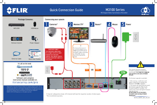
Select the day to playback
Select channels to playback
Control PTZ cameras (not included) Adjust color settings View system information
Start/stop sequence mode Search and playback recordings Open manual recording controls Open Main Menu
VGA* OR HDMI
Software and complete instruction manual available on:
/pro
Information in this document is subject to change without notice. As our products are subject to continuous improvement, FLIR Systems, Inc. and our subsidiaries reserve the right to modify product design, specifications and prices, without notice and without incurring any obligation. E&OE © 2014 FLIR Systems, Inc. All rights reserved.
Select camera/live display view
1. In live view, right-click and click Main Menu.
1. From live view, right-click and then click Search.
Verizon Fios 设备安装说明书(包括路由器、教练盘、电视盒等)

ENCLOSED ITEMS YOU MAY NEEDFOR INSTALLATIONCOAX CABLE(S)ETHERNET CABLE (6')CABLE BARREL CONNECTOR (used when a coax cable extends from wall, and a coax wall outlet is not available)2-WA Y SPLITTERSPECIAL ORDERCABLES AND CONNECTORSDIGITAL ADAPTERCableCARDCOMPOSITE CABLESHDMI CABLEFiOS™ TV REMOTEFios™ QUANTUM GATEWA Y ROUTER + POWER CORDFios® EQUIPMENTSET TOP BOX + POWER CORDVerizon FiosSELF-INSTALLATION INSTRUCTIONS12STEP 1A: Fios ROUTER SETUPConnect the Coax CableConnect the Power CordOPTIONAL: If a TV will be connected to the same coax wall outlet as your router, connect a 2-way splitter as shown.Connect the Ethernet cable to the yellow port on your router and then to your computer.Coax Cable to FiOS Router43Lights on the Fios Quantum Gateway will turn whiteonce activated. (This may take up to 6 minutes).NOTE: Details about router placement and Wi-Fi signal strength are available at /biz fios quantumgateway .STEP 1B: INTERNET SETUPOpen an Internet browser and go to . Then follow the on-screen instructions to activateyour Internet service.SPECIAL FEATURESMake easy network connections with the WPS button:Y our Fios Quantum Gateway comes with a WPS button that allows for connection to your Wi-Fi network without manually entering a password. If your wireless device supports WPS, follow your device’s instructions.Special Login just for guests:G uest Wi-Fi Access creates a second secure network for guests, with a unique wireless network name and password. For instructions on how to set up, visit /bizfiosquantumgateway and open the Fios Quantum Gateway Guest Wi-Fi Setup Guide - Business.Back of TV3Connect the HDMI Cable2Connect the Coax Cable1Connect the Power CordSTEP 2A: CONNECT YOUR SET TOP BOX USING HDMI CABLE (recommended for HDTVs)Back of TV3Connect the Coax Cable1Connect the Power CordALTERNATE OPTION: CONNECT YOUR SET TOP BOX USING COMPOSITE CABLE (for SDTVs)Connect theComposite Cable2STEP 2B: ACTIVATE YOUR SET TOP BOXTurn on your Set Top Box and your TV. Then, using your Fios TV Remote, follow the instructions shown on your TV screen.If you have additional Set Top Boxes, install them now following the directions in Step 2A & B.Connect theCoax CableConnect the Coax Cable2Connect the Power Cord3Back of TVSTEP 4A: CONNECT YOUR DIGITAL ADAPTERSTEP 4B: ACTIVATE YOUR DIGITAL ADAPTER1. T urn on the Digital Adapter by pressing the Set Top Box button on the Fios TV Remote Control.2. T urn on your TV and tune to Channel 3, either manually or with the remote control that came with your TV.3.T o complete activation, call the Verizon Support Center at 1.855.372.2181 and provide the Digital Adapter serial numbers.Digital AdapterINSTALLING YOUR CABLECARD1. R ead through the instructions for your CableCARD-ready device and complete any setup.2. W hen the CableCARD is inserted, follow the on-screen instructions.3. When prompted, enter the activation code on your Verizon Customer Receipt.4. Select which method of activation you prefer and follow the instructions.a. Visit /fiostv/selfinstallb. By phone at 1.888.897.7499CableCARDIf you’ve also subscribed to voice service with Verizon, installation is simple. Just plug your phone into a wall jack. If you don’t hear a dial tone, try anotherwall jack. If you need additional support call 1.800.Verizon (1.800.837.4966).FOR SUPPORTCALL 1.800.Verizon (1.800.837.4966)VISIT v /bizfiosquantumgat eway for detailed instructions on setting up a wireless network. VISIT /tvremotecontrolsetup for instructions on how to program your Fios remote control.Order extra remotes or cables at /smallbusiness/accessories。
NuLook FlexWall 2 安装说明书

Installation lnstructions NuLook FlexWall2 Amico CorporationUser ResponsibilityPreparation Before InstallationThe installation instructions provided are for the Amico standard products. Slight modifications to the installations may be required. The product shipped to the job site may not be exactly as shown on the installation drawings. See additional sheets for project specifics where required.IMPORTANT: PLEASE READ CAREFULLY PRIOR TO START• Review and understand all instructions before commencing work.• Iinstallation of this Prefabricated System should conform to the local building codes.All on-site preparations must be done prior to the delivery of the Prefabricated System. Please contact Amico to confirm and review all information listed below. Failing to do so may result in discrepancies/misalignments during installation.Please Note These Keywords and Symbols:W ARNING: Steps where extra care should be taken to prevent injuries and damage.N OTE: Steps that point out helpful information.I MPORTANT: Be sure to observe this instruction.Installation / Testing:Testing of the FlexWall Systems shall be performed according to NFPA 99.N OTE: The “Rough-in Assemblies” can be pressure tested up to a maximum of 200 psi without the “Latch-valveAssembly” attached to it.W ARNING: Do not pressure test the system over 100 psi [690 kpa] if the “Latch-valve Assemblies” and "Hoses Assemblies" have been installed.1. Review a copy of the final approved shop drawing(s) and/or submittal package. These documents will provide youwith technical information specific to your installation, such as:• Equipment types and quantities • Wiring diagrams and rough-in locations • Room numbers and locations• Blocking locations•Shop drawings of each unit typeI MPORTANT: Before the installation of drywall, make sure the blocking required for mounting the prefabricatedsystem is installed at locations indicated on shop drawings.W ARNING: All wiring must be completed per the National Electrical Code and/or local electrical codes by a licensed electrician.2. Prepare the tools and hardware needed to complete the installation. Some common tools that may be required are:• Cordless drill/driver with common drill or drive bits • Ladder(s)• Hand tools (screwdrivers, wrenches, clamps, pliers, etc.)• Jigsaw or reciprocating saw• Laser- or Bubble-level 3Step 1 - Engine Installation1. Ensure top and bottom tracks are at correct height before fastening the Amico Engine.N OTE: Please refer to the dimensions indicated on shop drawings.2. Insert Engine into tracks using lift and drop method (Figure 1).Figure 1Engine InstallationBottom TrackRough Opening (No Flight Zone)Top Track Existing studs on site (provided by others)Engine3. Ensure the Engine's studs are plumb and level using a laser line and secure them to top and bottom building tracksusing hardware provided by others.N OTE: Use hardware compliant to the local building codes.4. Make all Medgas pipe connections to the main source.N OTE: Medical gas pipes and electrical are terminated as per shop drawing.W ARNING: Only for Back-to-back units with 3 5/8" studs; braze the gas pipes with caution to prevent any damage to the acoustic sheet.Figure 2Engine Placed in Rough Opening Blocking required behind drywall (provided by others). See approved shop drawings for the exact location.Secure the Engine tothe top and bottomtracks using hardwarecompliant to local building codes (hardwareprovided by others)4 Amico Corporation 5Step 3 - Panel Frame Installation1. Refer to the height indicated in the shop drawing to mark two horizontal lines to locate drillings for mounting ofhanging bracket on the wall.2. Mount the brackets on the wall using hardware compliant to local building codes, as per setup diagram (Figure 3 & 4).Step 2 - Drywall Installation(Provided by Others)I MPORTANT: Before installing drywall, make sure the blocking is provided on the exact location indicated on the approved shop drawings.1. Cut drywall as needed around the boxes, gases, and the termination box located at the top (Figure 4).2. Install on wall; hardware by others.3. Tape and paint as needed.Figure 3Figure 4Ceiling LineFloor LineBlocking (by others)Blocking (by others)Brackets secured to the wall (hardware by others)6 Amico CorporationN OTE: Hanging brackets are labeled for ease of identification.I MPORTANT: Only use the four color coded holes on the hanging bracket of the center section. follow the blocking location for the left and right sections.N OTE: Hardware used to mount the bracket to the wall is supplied by others.Figure 53. Remove device cover plates and panels.I MPORTANT: See Page 10 for panel removal and handling instructions.4. Lift the right unit and hang it over the brackets which are already installed on the wall, then the left unit, prior toinstalling the middle unit. 5. Align the sections and connect in 4 places along the vertical edges of each section (Figure 6), using the hardwareprovided as shown in (Hardware 1).I MPORTANT: Make sure the frames are flush along the top and front. (Figure 8). 7Figure 6Top View Detail/Cross SectionFigure 7Hanging BracketsBolt the frames togetherFigure 88 Amico Corporation6. Connect the hanging bracket to the prefabricated system support (Figure 9) using the provided self-drilling screws(Hardware 2). Use the number of screws listed below based on section size:a. 19" to 32" wide section = 2 screwsb. 32.1" to 48" wide section = 4 screws7. Connect the medical gases to the FlexWall Engine (Figure 10).N OTE: The ends of Hose Assemblies have gas-specific adapters meant to plug into the FlexWall Engine. Please refer to the Engine drawing on page 11 for Labeling Guidelines.N OTE: Medical gas hoses are terminated as per shop drawings.N OTE: The “Rough-in Assemblies” can be pressure tested up to a maximum of 200 psi without the “Latch-valve Assembly” attached to it.W ARNING: Do not pressure test the system over 100 psi [690 kpa] if the “Latch-valve Assemblies” and "Hoses Assemblies" have been installed.W ARNING: To prevent over tightening, use manual tools to connect the medical gas adapters onto the engine.W ARNING: Make sure to install the plugs provided by Amico on all the unused medical gas ports.W ARNING: Orient and secure gas hoses so that they do NOT create a “valley” (i.e., a “U”-shape).Figure 9Ceiling LineFloor LineBottom TrackTop TrackBlockingScrew provided by Amico (Hardware 2)Brackets secured to the wall (hardware by others) 98. Bring the pre-installed conduits with wire whips (loft) to the existing electrical device boxes by passing them throughthe openings between the frames.N OTE: If applicable, remove flex from cover plate, pull the flex conduit to desired electrical device boxes. Reinstall the cover plate.I MPORTANT: Make sure the labels on the conduit matches the labels on the Engine.9. Pull wires through the Engine conduits to the termination box and install cover plates over the box.10. Attach all removed items:• Panels (must clip in properly where applicable)• Devices and cover plates • Reinstall the rails (if applicable)I MPORTANT: Do not overtighten the medgas and electrical cover plates.I MPORTANT: (If Applicable) Install the Vertical Rails onto Frames with screws. Reinsert the Vinyl Strip into the Rail to cover the Screws. (Must use the same hardware removed from the rails in Step 3 of Panel Frame Installation ).Figure 1010 Amico CorporationPanel Removal/HandlingAccess Panels1. Use the provided suction cup to remove the middlepanel then the left panel, prior to removing the right panel. Be careful not to drop the panels.Panels with vertical rails and services1. Remove vertical rails, where applicable:• Remove Top Plate • Remove Insert Strip • Remove Screws2. Remove device cover plates and gases.3.Remove panels (using the provided suction cup)W ARNING:• Stack panels face to face to prevent damage.• Keep panels as flat as possible when handling or storing.• Do not drag panels on other panels in order to prevent scratch or scuff.•Panels must be stored in controlled environmentFigure 11Insert StripPanelGasesDevice Cover PlatesRailPart#: W-X-LIFTER-0475 11NuLook FlexWall - EngineTOPTOPTOPTOPTOPTOPGas portsOLOXYVLVACALAIRTOPVT VACV A OL C LVTERM BOX HIGH POWER TERM BOXHIGH POWER TERM BOX1234689115710VRAR ORHorizontal opening required to installstud frame is 52 1/8"2" [51 mm Termination Box fromTop of Stud TYP.81 5/8" [2,073 mm]Maximum Ceiling Height: 108"Minimum Unit Height: 90"Panel starts at 8"-10" AFFBlocking (provided by others)Blocking (provided by others)4 3/4" [120 mm]77 3/4" [1,975 mm]122" [3,099 m m ] [S t u d H e i g h t + 2" m i n .]64" [1,626 mm]33 5/8" [855 mm]19 5/8" [499 mm]View A-ANO FLY ZONEN OTE: Labeling Guideline as per the NOTE on page 8.Labeling GuidelinesLabel on DrawingGas Type and LocationVT Vaccum Top VL Vaccum Left VR Vaccum Right AL Air Left AR Air Right OL Oxygen Left OROxygen Right Amico Corporation | 85 Fulton Way, Richmond Hill, ON L4B 2N4, Canada600 Prime Place, Hauppauge, NY 11788, USAToll Free Tel: 1.877.462.6426 | Tel: 905.764.0800 | Fax: 905.764.0862Email:**************|ACA-IM-NULOOK-FLEXWALL 11.26.2021。
组装与安装步骤说明书
组装与安装步骤说明书一、引言本说明书旨在提供关于产品组装与安装的详细指导,确保用户能够顺利完成组装与安装过程。
请在使用产品之前仔细阅读并按照说明书的指引进行操作。
二、材料准备在开始组装与安装之前,请确保已准备好以下材料:1. 主体部件(列出具体零件清单)2. 工具(列出所需的工具清单)3. 组装与安装步骤说明书(本文所提供的)三、组装步骤1. 拆包检查将产品包装打开,并逐一检查零件,确保没有损坏或缺失。
如有问题,请立即联系售后服务。
2. 零件识别根据零件清单,逐一识别出每个零件,并按照图示或标识进行区分。
3. 板件组装1) 将A板件与B板件进行对齐,并使用螺丝刀将螺丝拧紧。
确保板件连接紧密稳固。
2) 重复以上步骤,将C板件、D板件等依次组装。
4. 部件连接将组装好的板件与其他部件进行连接,采用螺丝紧固。
请仔细阅读说明书,确保正确连接每个部件。
5. 系统安装如果产品包含电气或机械系统,请按照相关步骤进行系统的安装。
确保每个连接处牢固可靠,并将电源或其他必要的线路正确接入。
6. 螺丝紧固在组装完成后,请对所有的螺丝进行检查并重新紧固。
确保产品结构牢固,无松动的螺丝存在。
7. 功能测试在组装完成后,进行功能测试以确保产品的正常工作。
按照说明书中的操作步骤,对每个功能进行测试并记录结果。
四、安装步骤1. 安装位置选择根据产品的使用要求,选择适当的安装位置。
确保产品能够平稳放置,并有足够的空间进行操作和维护。
2. 安装固定根据产品特点和安装位置,使用合适的螺丝或者支架对产品进行固定。
确保产品在使用过程中不会晃动或倾斜。
3. 连接电源如有需要,将电源线正确接入产品,并确保电源供应的稳定性和安全性。
4. 水、气源连接如果产品需要水源或气源供应,请按照相关要求进行连接。
确保连接处无泄漏,并进行测试以保证供应的稳定性。
5. 管道布置如果产品包含管道系统,请按照规定进行管道的布置。
确保管道连接牢固、通畅,并符合相应的安全标准。
SINAMICS G120 PM240P-2硬件安装手册说明书

SINAMICS SINAMICS G120 功率模块 PM240P-2
硬件安装手册
基本安全说明
1
简介
2
安装
3
接线
4
检修与维护
5
技术数据
6
备件和附件
7
附录
A
06/2020
A5E37800827B AD
Байду номын сангаас
法律资讯
警告提示系统
为了您的人身安全以及避免财产损失,必须注意本手册中的提示。人身安全的提示用一个警告三角表示,仅 与财产损失有关的提示不带警告三角。警告提示根据危险等级由高到低如下表示。
1.1
一般安全说明 ..................................................................................................................... 7
1.2
静电场或静电放电可导致设备损坏................................................................................... 13
1.3
应用示例的质保规定 ........................................................................................................ 14
1.4
安全性信息 ....................................................................................................................... 15
M2安装手册中文
安装手册
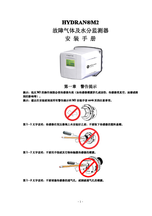
第一章 警告提示
提示:违反 M2 的操作规程会使传感器失效(如传感器薄膜穿孔或刮伤,传感器受真空,油漆或溶 剂的影响等)。 提示:建议在安装前阅读所有警告提示和 M2 安装手册 xxvii 页的注意事项。
图 1-1 文字说明:传感器在变压器阀上未安装好之前,不要取下传感器的塑料盖帽。
图 A-2 文字说明:用笔记本电脑的本机通讯 笔记本电脑:固定的波特比(等于 M2 的比特/秒),8 个数据比特,无极性,1 个停止比特,无流 向控制
图 A-3 文字说明:RS-485 导管的接地 (上)电缆接到 RS-485 的输入接线端,接地导管接到接地接线片。 (下)电缆接到 RS-485 的输出接线端,M2 的传导是隔离传导。
图 2-7 文字说明:脱开传感器的电缆 1. 反时针旋转传感器的连接器(约 1/8 圈) 2. 从传感器上拉出连接器
-7-
图 2-8 文字说明:用特氟纶(绝缘材料)带覆盖传感器的螺纹 顺时针缠绕在螺纹上
图 2-9 文字说明:用手将传感器安装在阀门上,再用活动扳手拧紧 1. 将传感器插入阀门 2. 用手旋入 3. 再用扳手拧紧
-9-
图 2-12 文字说明:将 M2 上紧在传感器上(第一部分)——门阀安装 1. 将传感器的凸型连接器接入凹型连接器 2. 旋转连接器(约 1/8 圈) 3. 将外壳摆正接到传感器上,注意不要挤压到传感器电缆 4. 旋转外壳(约 1/8 圈)直到外壳锁定
图 2-13 文字说明:将 M2 上紧在传感器上(第一部分)——球阀安装 1.将传感器的凸型连接器接入凹型连接器 2.旋转连接器(约 1/8 圈)
图 3-2 显示屏概观 Non-selected item 非选择项 Selected item 选择项(颜色被反转) 用箭头键选择显示屏上的其它项 Identification numberM2 的识别码 Time,……时间,或菜单名,或当前显示的选项 Context key messages 设置键消息 Scrolling indicator 滚动显示指示器 3.1 置定日期和时间
菲仕伺服电机使用说明书(第二版)
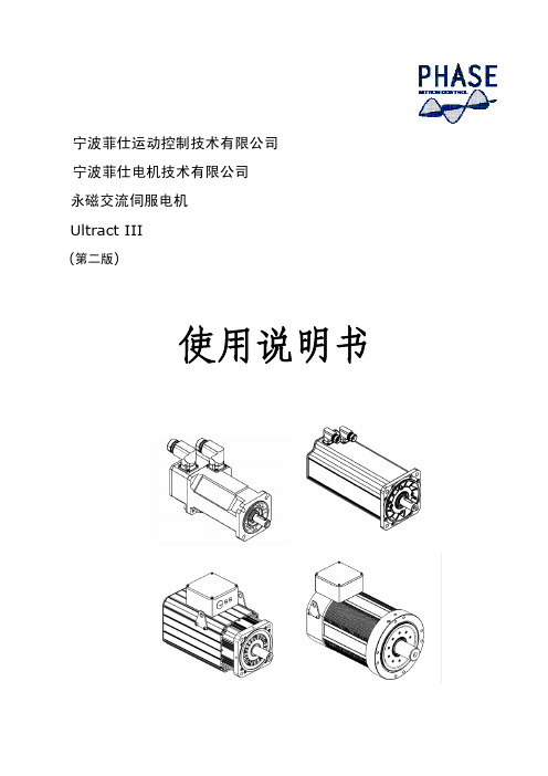
宁波菲仕运动控制技术有限公司宁波菲仕电机技术有限公司永磁交流伺服电机Ultract III(第二版)使用说明书目录一、概述 (3)二、规范说明 (3)三、检查 (3)四、安装 (4)五、编码器配置 (4)六、接线 (6)七、PHASE电机与驱动器接线 (10)Ⅰ、匹配PHASE驱动器接线 (10)(1)、配置正余弦编码器接线 (10)(2)、配置绝对值编码器接线 (11)(3)、配置旋转变压器接线 (12)Ⅱ、匹配LENZE驱动器接线 (13)(1)、配置旋转变压器接线 (13)(2)、配置绝对值编码器接线 (14)(3)、配置数字增量式编码器接线 (15)Ⅲ、匹配KEB驱动器接线 (16)(1)、配置正余弦编码器接线 (16)(2)、配置旋转变压器接线 (17)(3)、配置绝对值编码器接线 (18)Ⅳ、匹配SIEMENS驱动器接线 (19)(1)、配置正余弦编码器接线 (19)(2)、配置旋转变压器接线 (20)Ⅴ、匹配Schneider驱动器接线 (21)(1)、配置旋转变压器接线 (21)(2/3)、配置绝对值编码器接线 (22)Ⅵ、匹配B&R驱动器接线 (24)(1)、配置绝对值编码器接线 (24)Ⅶ、匹配CT驱动器接线 (25)(1)、配置绝对值编码器接线 (25)Ⅷ、匹配Kinwaytech(御能)驱动器接线 (26)(1)、配置旋转变压器接线 (26)Ⅸ、匹配Inovance(汇川)、Modrol(蒙德)驱动器接线 (27)(1)、配置旋转变压器接线 (27)Ⅹ、匹配Vector(威科达)驱动器接线 (28)(1)、配置数字增量式编码器 (28)八、运行与维护 (29)衷心感谢您选用菲仕伺服电机,为使本电机一直维持良好的运行状态,请将本手册随整机附送给最终用户。
虽然在您的选型过程中,可能已经对本产品有所了解并与本公司的技术人员进行了某些沟通,但为充分发挥本电机最佳功能,仍请在使用前,仔细阅读本使用说明书,必要时请与PHASE的有关人员联系,获得必要的帮助,以便正确的使用和维护电机,使之运行可靠,经久耐用。