CPXD-200使用说明书
Pundit PL-200 触摸屏操作手册说明书

®操作说明A Pundit 触摸屏B 电池C 两个 54 kHz 的传感器*D两条 1.5 米的 BNC 线*E 耦合剂*F 校准棒*G BNC 适配器线H 电源IUSB 线J DVD 光盘(含软件)K 文档L背带*标准配件 – 如果仅购买“不带传感器的 Pundit 触摸屏”(产品编号 327 10 002)EACHLI GFDBJK物品清单Pundit PL-200 概述112345678910112目录1. 安全和责任 (5)1.1 通用信息 (5)1.2 责任 (5)1.3 安全说明 (5)1.4 正确使用 (5)2. 技术规格 (6)3. 使用 (6)3.1 入门指南 (6)3.2 主菜单 (7)3.3 设置 (8)3.4 测量屏幕 (10)3.5 基本测量模式 (12)3.6 特殊测量模式 (12)3.7 多种测量模式 (15)3.8 用 Pundit PL-200 测量 (17)4. 资源管理器 (18)5. 传感器选择指南 .........................196. 订购信息 . (21)6.1 单位 (21)6.2 传感器 (21)6.3 配件 (21)7. 保养和支持 (22)7.1 保养 (22)7.2 支持理念 (22)7.3 保修信息 (22)7.4 废物处置 (22)8. PL-Link 软件 (22)8.1 启动 PL-Link (22)8.2 查看数据 (23)8.3 调整设置 (24)8.4 导出数据 (25)8.5 更多功能 (26)8.6 转换曲线 (26)8.7 弹性模量计算器 (27)1. 安全和责任1.1 通用信息本手册包含了 Pundit 触摸屏的安全、使用和保养等方面的重要信息。
请在首次使用仪器前仔细阅读本手册。
请安全保管本手册以备将来参考。
1.2 责任我们的“销售和交付一般条款”适用于所有情形。
由于下列某种或多种原因造成的人身伤害或财产损失,我们不予担保,也不承担任何责任:• 未按照本手册所述的使用方法使用该仪器。
DX200快速使用手册

目录规格参数 6-8机械操作功能介 9-10接口及功能介绍 11-12基本操作 13-14关机/屏幕开启关闭/重置/电/连接电脑做USB声卡安卓常用功能介绍 15-23接网络/第三方APK应用的安装和卸载/知管理/USB连接/应用授权/固件升级/机、重启及系统切换播放器APK操作指南 24-43一、产品介绍DX200是 iBasso 推出的参考级音乐播放器 。
DX200用时超过一年, 并借助双ES9028PRO的情况下,达到了目前最高的实测数据指标 。
失真控制到了0.0002%,实现了名副其实的参考级别,另外信噪比动态范围都达到了 125dB的超高数据。
可换耳放卡设计让DX200可实现多种变化,适合不同的听音习惯和耳机搭配。
DX200可以播放PCM高达32bit/384kHz, 硬解DSD512。
支持多种音乐格式。
同时它还可以作为一台专业的 USBDAC使用。
安卓和Mango双系统,特别是安卓6.0系统的i 存在,让DX200的可玩性大大增强。
通过5G wif可以流畅无干扰的播放网络音频。
DX200做外DX100的升级后继, 我们实现了多个重大突破。
也愿国产音乐播放器越做越好 。
二、产品及配件DX200的皮套,有效保护机身。
指引:的快速使用说明。
卡:后需求时需要提供保修卡, 敬请妥-C数据线:X200进行充电及数据传输。
煲机线:线连接耳机输出口,保持音乐播放 DX200 处于煲机状态。
煲机能有助 DX200 内部的电容及其它电子到稳定状态,从而使 DX200 的声最佳状态。
线:接外部音频解码器。
三、主要特点MOS USB 接收芯片及Thesycon声卡驱动,提供完美易用的 USB功能cusilicone超低相位噪音飞秒晶振S 屏幕,768*1280分辨率,搭配式触摸屏,OCA无缝贴合PULPDDR34G内存及光纤输出G wifi及蓝牙4.0DXC及SDHC TF卡M3U播放列表mAh 3.8V 锂聚合物电池四、规格参数材质:铝合金屏幕:4.2"IPS触摸屏(768*1280)格式:APE、FLAC、WAV、WMA、ALAC、AIFF、OGG、MP3、DFF、DXD同时支持CUE、M3U、M3U8连接:Type-C(数据传输和充电)输出接口:3.5mm同轴&光纤输出耳放卡:3.5mm单端耳机输出、线性输出、2.5mm平衡输出容量:4400mAh 3.8V 锂离子聚合802.11 b/g/n/ac(2.4Ghz/5Ghz)蓝牙V4.0重量:128.5mm*69mm*19.5mm 240gN:< 0.0002%, -114dB(64Ω@3Vrms) -122dBm 耳机输出平:3Vrms应:20Hz-20KHz -0.16dB:122dBN:0.00032%, -110dB(32Ω@1.8Vrms) -118dB输出平:3Vrms应:20Hz-20KHz -0.16dB:122dBN:< 0.00025%,-112dB五、机械操作功能介绍量调节旋钮:DX200的音量,向上旋转增加音向下旋转减小音量。
200w光束灯说明书
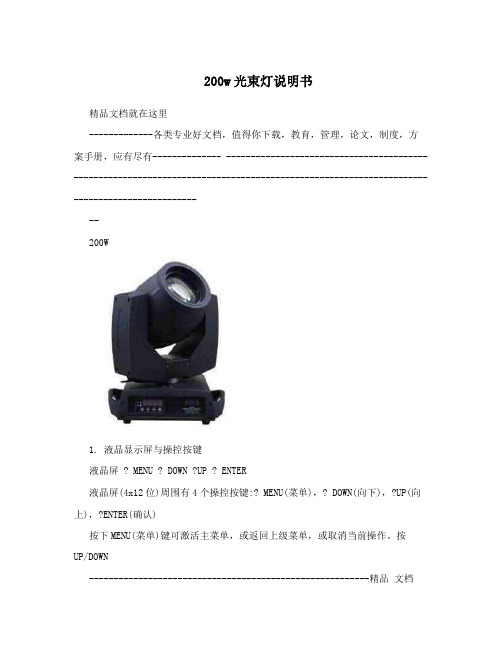
200w光束灯说明书精品文档就在这里-------------各类专业好文档,值得你下载,教育,管理,论文,制度,方案手册,应有尽有-------------- --------------------------------------------------------------------------------------------------------------------------------------------200W1. 液晶显示屏与操控按键液晶屏 ? MENU ? DOWN ?UP ? ENTER液晶屏(4x12位)周围有4个操控按键:? MENU(菜单),? DOWN(向下),?UP(向上),?ENTER(确认)按下MENU(菜单)键可激活主菜单,或返回上级菜单,或取消当前操作。
按UP/DOWN---------------------------------------------------------精品文档---------------------------------------------------------------------精品文档就在这里-------------各类专业好文档,值得你下载,教育,管理,论文,制度,方案手册,应有尽有-------------- --------------------------------------------------------------------------------------------------------------------------------------------(向上/向下)键可翻看菜单选项,或增减参数数值。
按下ENTER(确认)键可确认操作。
灯具在通电启动时,显示屏会显示:光束灯Reset如果灯具已经接好了DMX控制器,在启动完成后,显示屏会显示:光束灯DMX ReceiveADDR: 001此时,灯具已经可已经可以接受控制器操控(“ADDR”表示灯具当前的DMX地址码。
XD中文说明书
(型号 CMH-2301)
焊接电源 输入侧电缆
气体流量计 气管
控制电缆(6芯) 焊枪侧电缆 (请将其于焊接电源的+相连接。)
接地
送丝机 (型号CMX(L)-2302)
遥控盒(置于送丝机上)
焊枪
工件
工件侧电缆
接地
4.2 附件 名称
机种
XD200
XD350
XD500 数 量
栓遥形控保盒险 玻璃管保险 根角六螺弹光圆角螺头母垫垫栓螺栓
*钢瓶倾倒会引发人身事故。 *钢瓶内装有高压气体,错误使用会引发人身事故。 ●关于如何使用钢瓶,请依照法规与贵公司内部基准。 ●气体流量计请选用本公司附件或本公司推荐产品。 ● 前 流量 在使用 ,请阅读气体 计使用说明书并遵守注意事项。 ●请勿高温曝晒气体钢瓶。 ●请使用专用的支架固定气体钢瓶。 ●打开气体钢瓶阀门时,请勿将脸部靠近出气口。 钢瓶 罩好 罩 ●不使用气体 时,请务必 保护 。 ●请勿将焊枪挂在气体钢瓶上、勿使电极接触钢瓶。 旋转 成 , 定 注意 接触 部位会造 伤害 务请遵守以下规 。
用语予以警告,此标识符及警告用语在电焊机中亦表示相同的意思。
提请注意标识符
警告用语
内Hale Waihona Puke 容高度危险误操作后极度危险,可能引发重大人身事故。
危险
误操作后危险,可能引发重大人身事故。
注意
误操作后发生危险,可能引发中度伤害或轻伤。或只遭受物 质损失。
·注意标识符表示一般情况。 ·上述重大人身事故是指失明、外伤、烫伤(高温、低温)、触电、骨折、中毒等,会遗留后
场 近 灭火 防万 ●请在焊接操作 所附 放置 器,以 一。
-5-
No. C0049
2. 敬请遵守的安全事项(续)
下载-OTC焊机特点及参数
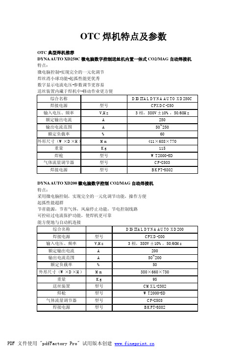
OTC焊机特点及参数OTC典型焊机推荐DYNA AUTO XD250C微电脑数字控制送丝机内置一体式CO2/MAG自动焊接机特点:微电脑控制-实现完全的一元化调节焊丝消小球功能-起弧性能更优秀数字显示电流电压-参数调节更容易送丝装置内藏于焊机中-移动作业更方便综合名称DIGITAL DYNA AUTO XD250C 焊接电源型号CPXDC-250输入电压、频率V,Hz3相,380V±10%,50/60Hz 额定输出电流A250输出电流范围A50~250额定负载率%60外形尺寸(W×D×H)Mm411×688×770重量Kg115焊枪型号WT2000-SD 气体流量调节器型号CF-2503焊接电源型号BKPT-3802DYNA AUTO XD200微电脑数字控制CO2/MAG自动焊接机特点:采用微电脑控制,实现完全的一元化调节功能,操作方便起弧性能超群节省能源,节省气体,风扇停止功能,节电控制线路可控硅过电流保护功能,使焊机更可靠能方便地与自动机连接综合名称DIGITAL DYNA AUTO XD200焊接电源型号CPXD-200输入电压、频率V,Hz3相,380V±10%,50/60Hz额定输出电流A200输出电流范围A50~200额定负载率%50外形尺寸(W×D×H)Mm380×660×730重量Kg95送丝装置型号CMXL-2302焊枪型号WT2000-SD 气体流量调节器型号CF-2503焊接电源型号BKPT-3802DYNA AUTO XD350S·500S微电脑数字控制CO2/MAG自动焊接机特点:熔深控制功能——即使焊丝伸出长度有变化,也能保护焊接电流稳定采用微电脑控制,实现完全的一元化调节功能,操作方便起弧性能超群节省能源,节省气体,风扇停止功能,节电控制线路可控硅过电流保护功能,使焊机更可靠能方便地与自动机连接综合名称焊接电源型号CPXDS-350CPXDS-500输入电压、频率V,Hz3相,380V±10%,50/60Hz额定输出电流A350500输出电流范围A50~35050~500额定负载率%5060外形尺寸(W×D×H)mm343×615×732400×607×850重量Kg110152送丝装置CMXL-2302焊枪型号WT3510-SD WT5000-SD 气体流量调节器型号CF-2503焊接电源型号BKPT-3802BKPT-6002DYNA AUTO XD600G微电脑数字控制多功能CO2/MAG自动焊接机特点:焊接条件设定完全的一元化调整,操作方便一机多用,同时实现CO2/MAG焊、气刨,手工焊接。
贝士德FC200使用手册

目 录录第一章第一章、、 概述概述1.1前言 (1)1.2检查与安全注意事项..................................................1 1.3规格型号表..........................................................4 1.4制动单元与制动电阻.. (6)第二章第二章、、 安装与接线安装与接线2.1机箱结构和尺寸......................................................7 2.2安装要求............................................................9 2.3接线要求............................................................10 2.4接线说明 (11)第三章第三章、、 运行操作运行操作3.1操作面板............................................................16 3.2操作键盘说明........................................................16 3.3显示内容说明........................................................17 3.4参数修改方法........................................................18 3.5试运行.. (18)第四章第四章、、 功能参数说明··············································19 第五章第五章、、 参数详解···················································30 第六章、故障处理方法故障处理方法6.1维护检查注意事项....................................................62 6.2定期检查项目........................................................62 6.3故障信息及故障排除..................................................62 6.4故障及分析..........................................................65 6.5常见异常现象及对策.. (67)第七章、 品质承诺品质承诺·· (68)1第一章第一章 概概 述述1.1前言前言感谢您选用FC200系列高性能通用型变频器。
200 中文说明书

热冷水高压清洗机TOP 200说明书索引1产品介绍2警告提示3使用说明使用说明安装说明喷头的选择冷水使用说明热水使用说明洗洁液喷射使用说明关闭和存放说明4安全保护装置5定期检查6发现并维修故障TOP GUN 200 产品说明书1、产品介绍这说明书手册包含:安全配置、操作描述和维修常识。
请好好保管这个手册并存放在可以快速查阅的零件目录一起、容易拿到的地方。
而且要请仔细留意阅读它,在开始使用和运行以及机器维修之前要参照所有描述的操作说明、进行操作。
由于操作人员对这些内容不够重视、引起对人、对机器和物体的损伤,机器制造商将不负责任。
指示说明、图纸、图表和手册内其他内容都被认为是受保护的技术信息、因此不能部分和整体复制,没有制造商的同意,也不能提供给第三者。
制造商是这些信息独家拥有者,它有权在不须通知随意更改这些信息。
2、警示标识1、没有阅读指示说明手册不要使用机器。
2、电源的连接由专业熟练电工来进行操作,这种连接方法必须符合由电气组织颁布的最新IEC规则。
强力要求供电电源必须要有漏电装置,当漏电电流在30 MS时间内超过30MA 就切断电源,或者直接接地。
3、如果高压喷枪喷射不正确使用,将非常危险,喷射嘴不要对准人、物体、电器设备和清洗机自己。
4、在清洗和维修操作机器时,必须与电源断开。
5、任何时候关掉喷枪时,请拉出枪的扳机扣卡住6、机器被要求使用制造商推荐和提供的清洁产品,其他的清洁剂和化学物质可能会危及机器安全性,只允许使用液体清洁液。
、7、高压清洗机不允许被小孩和不熟悉操作程序和手册上的陈述的警告提示的人使用。
8、请避免车辆靠近机器和挤压高压软管,高压软管对机器的安全性非常重要,万一要更换请使用原产的,如果需要配件和技术协助,请通知你最近权威的服务中心。
如果电线和高压管不是完好的,请不要使用,为了确保绝对安全,请更换原产品的机器配件。
9、当别人在附近时,请不要使用机器。
10、当使用机器时,请穿戴防护衣。
200X 扫地机器人操作手册说明书
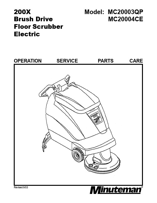
200XBrush DriveFloor ScrubberElectric Model: MC20003QPMC20004CE Revised 9/03OPERATION SERVICE PARTS CARETABLE OF CONTENTSPage Safety Instructions1 Electrical Requirements2 Control Panel Identification3 Operating Instructions4 Squeegee Adjustments5 Brush Installation/Removal6 Base Assembly7 & 8 T ank Assembly9 & 10 Upper Assembly11 Console Assembly12 Motor Lift Assembly13 Scrubhead Assembly14 Back Panel Assembly15 Assembly16 Squeegee Lift & Mechanism Assembly17 Squeegee Assembly Complete18 Wiring Diagram, 115V19 Wiring Diagram, 230V CE20FOR COMMERCIAL USE ONLYIMPORTANT SAFETY INSTRUCTIONSWhen using an electrical appliance, basic precautions should always be followed, including the following:READ ALL INSTRUCTIONS BEFORE USINGWARNING - To reduce the risk of fire, electric shock, or injury:•Do not leave appliance when plugged in. Unplug from outlet when notin use and before servicing, cleaning or maintaining.WARNINGTo reduce the risk of electric shock - Do not expose to rain. Store indoors.•Do not allow to be used as a toy. Close attention is necessary when usedby or near children.•This machine shall be used only by instructed and authorized persons.•Use only as described in this manual. Use only manufacturer’s recommendedattachments.•Inspect cord regularly. Do not use with damaged cord or plug. If applianceis not working as it should, has been dropped, damaged, left outdoors, ordropped into water, return it to a service center. Use only cord specifiedby manufacturer.•Do not pull or carry by cord, use cord as a handle, close a door on cord, orpull cord around sharp edges or corners. Do not run appliance over cord.Keep cord away from heated surfaces.•Do not unplug by pulling on cord. To unplug, grasp the plug, not the cord.•Do not handle plug or appliance with wet hands.•Do not put any object into openings. Do not use with any opening blocked;keep free of dust, lint, hair, and anything that may reduce air flow.•Keep hair, loose clothing, fingers, and all parts of body away from openingsand moving parts.•Do not pick up anything that is burning or smoking, such as cigarettes,matches, or hot ashes.•Do not use without dustbag and/or filters in place.•Turn off all controls before unplugging.•Use extra care when cleaning on stairs.•Do not use to pick up flammable or combustible liquids such as gasoline oruse in areas where they may be present.•Connect to a properly grounded outlet only. See grounding instructions.•This machine is not suitable for picking up hazardous dust.•Close tank and lid before use.SAVE THESE INSTRUCTIONSINSPECTIONCarefully unpack and inspect your machine for shipping damage. Each unit is tested and thoroughly inspected before shipment, and any damage is the responsibility of the delivery carrier who should be notified immediately.WARNING•Read Instruction Manual before operating this piece of equipment.•To reduce the risk of fire use only commercially available floor cleaners andwaxes intended for machine application.•To reduce the risk of electrical shock, do not expose to rain. Store indoors.•Do not cross over supply cord, hazard exists when rotating brush passesover cord.•Electrical motors and components can cause an explosion when operated near volatile materials and vapors. Do not use this machine near flammable materials such as solvents, thinners, fuels, grain dust, etc.ELECTRICAL(Model MC20003QP) This floor machine is designed to operate on a standard 15 amp. 120 volt, 60 hz, AC circuit. Voltages below 105 volt AC or above 125 volts AC could cause serious damage to the motor.(Model MC20004CE) This machine is designed to operate on a standard 16 amp. type L fused 230 volt, 50 hz, AC circuit. Voltages below 200 volt AC or above 250 volts AC could cause serious damage to the motor I.E. C. Class 1.GROUNDING INSTRUCTIONS•This floor finishing machine should be grounded while in use to protect the operator from electric shock. The machine is equipped with a three-prong grounding type attachment plug to fit the proper grounding type receptacle. The green (or green and yellow) conductor in the cord is the grounding wire. Never connect this wire to other than the grounding blade.•If the machine is provided with an attachment plug as shown in Sketch A it is intended for use on a 120-volt (nominal) circuit. If a properly grounded receptacle as shown in Sketch A it is intended for use on a 120-volt (nominal) circuit. If a properly grounded receptacle as shown in Sketch A is not available, an adapter as shown inSketch C is available and should be installed as shown in Sketch B if the outlet box that houses the receptacle is grounded. Be sure to fasten the grounding tab with the faceplate screw.ADAPTER (Not applicable in Canada)METAL SCREWGROUNDINGCOVER OF GROUNDED MEANSOUTLET BOXGROUNDING PIN (C)(A) (B)1.Squeegee lift lever2.Recovery dump hose3.Dashboard control panel4.Solution control lever5.Solution dump hose6.Quick disconnectAux. out (optional)7.Food pedal8.Receptacle9.Circuit breaker10.Main power11.Brush switch12.Vacuum switch13.Pump switch (optional)AUTO SCRUBBER BRUSH DESCRIPTION•Durability is dependent on floor surface, chemicals used and proper care.OPERATING INSTRUCTIONSBEFORE STATING, FAMILIARIZE YOURSELF WITHTHE MACHINE AND ITS CONTROLS (SEE “MACHINE OVERVIEW” & CONTROL PANEL DIAGRAMS)1.Filling: Fill the solution tank with the desired amount of water and add liquidcleaning solution to the proper dilution ratio. DO NOT USE powdered cleaningchemicals. Powders are unlikely to dissolve thoroughly, resulting in clogging thein-line solution filter. This can reduce or stop water flow to the brush.2.Close lid.3.Turn on machine by pressing the main power switch (10).4.Lower brush assembly.-To lower the brush, first push the pedal (7) slightly outward on the machine (unlock it), and then release it slowly.-To lift the brush, press the pedal (7) down until lift mechanism engages.5.Turn on brush (11).6.Adjust solution control feed lever (4).7.Turn on vacuum switch (12).8.Lower squeegee assembly by lowering handle (1).After Use:1.Turn off solution feed (4).2.Switch off brush (11) and raise (7).3.Raise squeegee assembly (1).4.Turn off vacuum motor (12).Solution and recovery tanks should be emptied after every use.MAINTENANCE:Daily 1.Clean float assembly & squeegee blades. Vac filter.Monthly 1.Check wear on squeegee blades.2.Grease front wheels.3.Grease pivot points on brush motor assembly.Every 500 hours check condition of carbon brushes on vacuum motor and brush drive motor.SQUEEGEE ADJUSTMENTSThe squeegee set up is pre adjusted at the factory. Adjustments may be required to get optimum performance for different floors and conditions.1Ensure that the scrubber is on a relatively flat surface. Turn on the main power switch and lower the scrubhead assembly to the floor.2Lower the squeegee (item 1) to the floor. Move the machine one or two feet forward to check the rear squeegee blade (item 8) for uniform deflection to the floor.3If uneven deflection or lay is evident, minor adjustments may be necessary to avoid streaking and uneven wear on the blade.4To correct this, loosen the wing jam nut (item 4) in order to adjust the castor height. If the squeegee blade is deflecting too much, the castors need to be lowered to control the down pressure. Lower the castor by turning the exposed threaded stem (item 9) on the castor clockwise. Make the adjustment a few turns at a time. Repeat Step 2.5If the blades are not deflecting enough, raise the castor by turning the stem counter clockwise to adjust the castor height to allow more down pressure on the squeegee. Repeat Step 2.6Make sure that there is an even deflection on the entire length of the rear blade. Adjust the castors and retighten the wing jam nuts to lock the castor setting in place.7Pitch adjustment is necessary if the outer ends on the squeegee blade does not contact the floor and there is too much deflection in the middle area or if the outer ends are over deflected and there is no contact in the middle.8To adjust the pitch, lower the squeegee to the floor. Loosen the lock nut (item 3) in the turnbuckle assembly. Turning the turnbuckle (item 2) clockwise or counter clockwise controls the forward and backward pitch of the squeegee. Having the rear blades deflected uniformly along the entire length is the desired set up.9Repeat Step 2 until the desired set up is achieved.10In certain applications where a non-slotted front wiper blade (item 6) is needed, detach the squeegee assembly by loosening the wing bolts (item 7). Unlock the clamp on the front squeegee to release the straps and flip the blade over to the non-slotted side. Reattach straps and lock the clamp back in place. 11You can also easily replace the rear blade by unlatching the latch (item 6) and removing the straps by sliding them off the assembly.BRUSH INSTALLATION - REMOVALINSTALLATION1.Raise the scrubhead to the “UP” position by depressing the pedal (A) downward asshown on Fig. 1.2.Center brush (D) under the scrubhead shroud while lining up the centerhex drive hub and pressing the brush up until the brush engages on the drive hub. REMOVAL1.Raise the scrubhead to the “UP” position by depressing the pedal (A) downward asshown on Fig. 1.2.Remove the brush (D) by stepping on the “BRUSH RELEASE PIN”on the top of the scrubhead shroud as shown on Fig. 1 below.Figure 1BASE ASSEMBLYBASE ASSEMBLYParts ListItem Part No.Qty.Description12001021Base22002501Axle Weldment37123012WSR-Flat .38 x .88 x .06 47623322Wheel, 8 x 2 w/Bearing 57113751Nut-Nyloc 3/8-1667115781WSR-Flat 1/2 Brass 77123182WSR-Flat 3/4 x 1.12 x .12 87127592WSR-Flat 5/16 x 1.37 x .06 SS 97120422Bolt-WSR HH 5/16-18 x .62 1071154430WSR-Helical 1/4 1171120319BLT-HH 1/4-20 x .62 1271150511WSR-Flat 1/4132001581Pin Bracket142001531Squeegee Mechanism Assy. 157118081Cotter Pin162104151Clevis Pin 5/16177113732Nut-Nyloc 1/4-20187125641Bolt-HH 1/4-20 x 1 SS 192002651Back Panel Assy., BD 202003141Electrical Box Cover 217111254SCR-ST-B #10 x 1/2 227130028BLT-HH 1/4-20 x .75 232003452Caster, 3 1/2”242001251Battery Tray Weldment 252100481Battery Liner267125655SCR-MC 1/4-20 x .62 SS 272001451Hinge282001461Hinge Plate297112284Bolt-HH 5/16-18 x 3/4 307115074WSR-Flat .37 x 1.12 x .06 312002331Bottom Cover327128223SCR-THMS 10-24 x 1/2 332002351Hose Nylobraid 17.50 344500762Crimp Clamp 185R SS 352003151Scrubhead Assy. 115V35A2003281Scrubhead Assy. 240V 362001861Motor Cover372002801Motor Lift Assy.38712099PLT2Shoulder Bolt 1/2 x .50 397115104WSR-Flat .50 x 1.38 x .10 407115454WSR-Helical 5/16 412001301Pawl Weldment422002601Solution Valve Assy. - BD 432002341Solution Hose 51.00 447113163Nut-Hex 1/4-20452001291Pawl Mounting Bracket 467115754WSR-Flat .312 x .75 x .06 47200318MCH1Reservoir487129082Nut-Wizz 10-24492601831Nut-Nylon 1/4 NPT 508333251Barb 90° Elbow 3/8 x 1/4 NPT 5182-54-A1Clamp527111061SCR-ST-A 10 x .75 PL 537115832WSR-Wave .78 x 1.00 x .02TANK ASSEMBLYTANK ASSEMBLYParts ListItem Part No.Qty.Description12001011Solution/Recovery T ank 22001473Bracket, Vac Motor 32001731Float, Housing42101221Drain Hose Wirelock 52002321Cable, Tank62002511Stand Pipe Assembly 72002581Muffler Assembly82002701Hose, ¾ Solution Drain 92000231Garden Hose Cap 102104091Fitting, Brass 3/8 MPT 112104101Fitting, Brass 3/8 FPT 122104141“O” Ring 2-113132500383Clamp, Plastic 5/16 3305 142602031Hose Clamp 102120 Murray 152900171Gasket, Molded, Vac Motor 167608591Clamp-Hose 3” NOM 173833211Elbow ¾ MPT ¾ Barb PP 182000221¾” MGHT x Hose Barb 198291292Clamp, Crimp ¾ Barb 204300501Filter Screen 4 x 4 212601551Foam Float222003201Shut Off Weldment 234600191Gasket247102071SCR-MC 6-32 x .87 ST PL 252002341Solution Hose261301181Solution Strainer 277125403SCR-MC #10-24 x .375 SS 287125741CR Bolt SS ¼-20 x 3”297126672Nut-Hex ¼-20 SS Nyloc 302002311Gasket, Shutoff317125681SCR-MC ¼-20 x 2.25 SS 328329961Terminal Block 2-Pole VDE 338333161Drain Plug347402321Vac Motor 115V34A7410301Vac Motor 240V357602452Hose Clamp 62P24 367603431Tube Hose 24/32B 377623842Bushing .277 x .375 x .37 SS 388300621Fitting Brass 90 3/8 MPT 397101803SCR-MC ¼-20 x .75 407115446Lockwasher - Helical ¼417115056Washer ¼427152851Decal, 200X432000241Black Vinyl Washer 447127594WSR-Flat .31 x 1.37 x .06 SS 453100081O-Ring467125653SCR-MC 1/4-20 x .625 SS 478056131Hose Cuff, Grey Vinyl 483202691Strap, Drain Plug RetainingUPPER ASSEMBLYParts ListItem Part No.Qty.Description12003101Tank Assembly 115V1A2003271Tank Assembly 240V22001782Gasket, Lid32001361Gasket, Solution Lid42001031Tank Lid57121202Shoulder Bolt ½ x 267101786SCR-MC ¼-20 x ½77115032WSR-Flat #1087111255SCR-ST-B #10 x ½97602861Wire Formed Hook102001761Dump Hose Bracket112003301Console Assy. - Electric127152841Decal, Solution Control133833671Spring Clip144300531Solution Control Cable157112286Bolt-HH 5/16-18 x ¾167115456WSR-Helical 5/16177115756WSR-Flat 5/16182000321Console Back Cover Weldment194500541Vacuum Recovery Hose202001521Solution Control BracketCONSOLE ASSEMBLYParts List for 200330Item Part No.Qty.Description12001041Console22001341Console Bracket Right32001351Console Bracket Left42001511Hinge Bracket Weldment5200322SP1Dashboard ASM BD67123204WSR-Nylon .22 x .45 x .0477125408SCR-MC #10-24 x .37 SS87115756WSR-Flat .31 x .75 x.0697115456WSR-Helical 5/16107112286Bolt-HH 5/16-18 x .75117115052WSR-Flat ¼122002401Squeegee Lift Assy.137115446WSR-Helical ¼147112036Bolt-HH ¼-20 x .62157407113Switch (optional 4th)167408113Switch Boot (optional 4th)178338271O-Ring 1.25 ID x .187182500381Retainer Bag Clip198302921Cord Assy. 75 ft. 115V19A7432871Cord Assy. 25 Meters 240V204301031Snap Body217601421Clamp Ring224500121Strain Relief237111611SCR Hi-Lo 10 x .75MOTOR LIFT ASSEMBLYParts ListItem Part No.Qty.Description12001201Base Plate Weldment22600362Pin37123104WSR-Flat .52 x .88 x .0647115276WSR-Flat 5/8 x 1.12 x .1257623402Oilite Bushing 1/262600414Oilite Flanged Bushing 1/272001151Lift Arm Weldment87117132E-Ring 1/297102072SCR-MC 6-32 x .87107401281Microswitch117114301Tinnerman Clip128336382Brass Stud137113682Wing Nut147401322Insulator Glastic157115462WSR-Helical 3/8167130412Bolt-HH 3/8-16 x 3/4 #5177113761Nut-Nyloc 1/2-13182601371Compression Spring192001101Spring Bracket202001491Adjustment Rod212001161Pedal Arm Weldment222101421Pedal Pad234500402Elbow 3/8 Barb x 3/8 MPT24809413MCH1Solution Valve Machined258294631WSR-Flat SS268289751WSR-Neoprene .75 x 1.5 x .09272002591Valve Bracket287115131WSR-Flat .689 X 1.06 X .029 SSSCRUBHEAD ASSEMBLYParts ListItem Part No.Qty.Description12001091Motor Platform Weldment - BD22001871Brush Shroud Weldment32001941Pin, Brush Release42002942Shroud Strap52100661Retainer Bolt62002931Shroud Skirt72601831Nut 1/4 NPT Nylon88336211Key, 1/4 x 1/4 x 1.0094300351Drive Hub105000331Locking Screw117109864SCR-SC 3/8-16 x 1.00127112023SCR-MC 1/4-20 x 1/2137115443WSR-Helical 1/4147115191WSR-Flat .25 x 1.01 x .06157123181WSR-Flat 3/4167404281Gear Motor 115V16A7404321Gear Motor 240V178331021Spring188333251Hose Barb 90° Nylon197115782WSR-Flat 1/2 Brass207123108WSR-Flat .52 x .87 x .06214300852Bumper Wheel227127592WSR-Flat .31 x 1.37 x .06 SS237109752SCR-SC 5/16-18 x .87247125608SCR-MC 1/4-20 x .50 Nyloc252000291Pitch Adj. Bar Weldment267113341Nut-Hex 1/2-13277107541Bolt-HH 1/2-13 x 2 3/4287115051WSR-Flat 1/4297113731Nut-Nyloc 1/4-20307434251Ground WireBACK PANELParts ListItem Part No.Qty.Description17423072Switch, McGill, VDE22002291Bracket, Kill Switch37103074SCR-MC 6-32 x 142003261Cover Switch Box571112510SCR-ST #10 x .567113162Nut-Hex ¼-2077115442WSR-Helical ¼87114302Nut-Tinnerman 6-3292003321Wire Guard Cover102003111Back Panel Weldment117427481Boot, Circuit Breaker127402201Circuit Breaker, 20A138305401Flg. Male Receptacle 115V13A8326821230V Receptacle142003171230V Receptacle Bracket157422561RFI Filter 230V Only167128182SCR-MC 10-24 x .5177413001Terminal Block187402021Receptacle Bridge197128135SCR-MC 10-24 x .75207129082Nut-Flange Wizz 10-24217126352Nut-Hex 10-24 SS227115432WSR-Helical #10B AC K P A N E LD A S H B O A RD P a r t s L i s t f o r 200299I t e m P a r t N o .Q t y .D e s c r i p t i o n 12001791D a s h b o a r d P l a t e 27152831D e c a l 200 D a s h b o a r d 37402161B a t t e r y G a u g e 47407113S w i t c h D r e e f s 57422021D i s c o n n e c t S w i t c h 125A 67408113S w i t c h B o o tP a r t s L i s t f o r 200265I t e m P a r t N o .Q t y .D e s c r i p t i o n 12001241B a c k p a n e l W e l d m e n t 27427492C i r c u i t B r e a k e r P l u g 37113682W i n g N u t , 1/4-2047401322I n s u l a t o r (G l a s t i c )57427482B o o t , C i r c u i t B r e a k e r 67402471C i r c u i t B r e a k e r 3077420002D i o d e A s s e m b l y 87405491C i r c u i t B r e a k e r 5097112102S C R -H H 1/4-20 x 1 1/4107401591C B 175 R e d H o u s i n g O n l y 117432601W i r e H a r n e s s , 200X B D 127881472S o l e n o i d 24V D C 138336382B r a s s S t u d 147114256W h i z -N u t 1/4-20S Q U E E G E E M E C H A N I S MS Q U E E G E E L I F T P a r t s L i s t f o r 200240I t e m P a r t N o .Q t y .D e s c r i p t i o n 12002391P a n e l C o v e r W e l d m e n t 27156031D e c a l S q u e e g e e L i f t 32002411S q u e e g e e L i f t C a b l e 42002611I n n e r A r m W e l d m e n t 52000171A r m S q u e e g e e L i f t W e l d m e n t 67120811B o l t , S h o u l d e r 5/16 x .7578319651C l e v i s P i n 3/888093111C o t t e r p I n 7/64 x 1”98810091Y o k e 108810021C l e v i s P i n 5/16117118081C o t t e r P i n #131********B o l t -S H L D E R 5/16 x .44132000381H a n d l e W e l d m e n t 1471164213/16 x 1.00 R o l l P i n 157115042W S R -F l a t 1/4 S SP a r t s L i s t f o r 200153I t e m P a r t N o .Q t y .D e s c r i p t i o n 12001441S p r i n g H o u s i n g W e l d m e n t 22003001Y o k e W e l m e n t 32103751S w i v e l P i n 42103912R e t u r n S p r i n g S S 52104151C l e v i s P i n .31 x 1.7 11-0976*******O i l i t e F l a n g e B u s h i n g 77101801S C R -M C 1/4-20 x .75 S T P L 87115441W S R -H e l i c a l 1/497115191W S R -F l a t .25 x 1.01 x .06107118081C o t t e r P i n - H a i r #131********W S R N y l o n .22 x .45 x .0412*******S p r i n g , T o r s i o n R H 139000811S p r i n g , T o r s i o n L H 142001591P i n 157125364S C R -M C 10-24 x .62 S S 167125641B L T -H H 1/4-20 x 1.00 S SParts List for 200348Item Part No.Qty.Description12000642Caster Wheel 3/8”-16 x 1-5/8”22000651Castor Support Bracket 32001691200X Sq Lift Weldment New 42003421Squeegee Brkt Weldmt, 200X 52003441Top Plate Weldmt, 200X LH 62003471Top Plate Weldmt, 200X RH 72101532Roller Wheel82202492Wing Bolt 1/2-13 x .75”92600662Oilite Bushing102602421Front Squeegee Blade 260 112602431Rear Squeegee Blade 260 122602481260 Sq. Casting w/Roll Pin 132603391Strap - Rear Latch 260 142603441Strap - Front Stop 260 152603461Strap - Rear Catch 260 162810741Squeegee Toggle Clamp, 2800 172810751Squeegee Latch, 2800 182817401Stop Bar193203081Strap-Front Clamp 320 203834241Mounting Bracket-Right 213834251Mounting Bracket-Left Item Part No.Qty.Description227105307SCR-MC 8-32 x .50 BR 237110265Nut, Hex 8-32 Nyloc SS 247112414SCR-Hex 3/8-16 x .75” ZP 257113672Nut-Wing 3/8-16 ST PL 267115044WSR-Flat 1/4 ID SS277115074WSR-Flat .37 x 1.12 x .06 287115091WSR-Flat 1/2 (.54 x 1.08 x .087) 297115242WSR-Wave .52 x .87 x .01 307115466WSR-Helical 3/8317115922WSR-Nylon .50 x 1.06 x .06 327116683Cleavis Pin, 3/8 x 1 11-141 337117132Retaining Ring - “E” Type Ext .500 347118083Cotter Pin - Hair #13 357123016WSR-Flat .87 x .37 x .06 367125644Bolt-HH 1/4-20 x 1.00 SS 377126672Nut, Hex 1/4-20 Nyloc SS 387126801Nut-Hex 5/16-18 SS 397127584WSR-Helical 1/4 SS407506891Adjustment Stud41762022PLT1Nut, Adjusting (LH)42762257PLT1Nut, Adjusting (RH)WIRING DIAGRAM, 115VWIRING DIAGRAM, 240V CELIMITED WARRANTYMinuteman International, Inc. warrants to the original purchaser/user that this product is free from defects in workmanship and materials under normal use and service for a period of three years from date of purchase. In addition, Minuteman International, Inc. will, at its option, honor labor warranty claims for the first 12 months from date of sale, provided such claims are submitted through and approved by factory authorized repair stations. Minuteman International, Inc. will, at its option, repair or replace without charge, except for transportation costs, parts that fail under normal use and service when operated and maintained in accordance with the applicable operation and instruction manuals.This warranty does not apply to normal wear, or to items whose life is dependent on their use and care, such as belts, cords, switches, hoses, rubber parts, electrical motor components or adjustments. Parts not manufactured by Minuteman International, Inc. such as engines, batteries, battery chargers, hydraulic pumps, and tires are covered by and subject to the warranties and/ or guarantees of their manufacturers. Please contact Minuteman International, Inc. for procedures in warranty claims against these manufacturers.Special warning to purchaser — Use of replacement filters and/or prefilters not manufactured by Minuteman International, Inc. or its designated licensees, will void all warranties expressed or implied.A potential health hazard exists without exact original equipment replacement.All warranteed items become the sole property of Minuteman International, Inc. or its original manufacturer, whichever the case may be.Minuteman International, Inc. disclaims any implied warranty, including the warranty of merchantability and the warranty of fitness for a particular purpose. Minuteman International, Inc. assumes no responsibility for any special, incidental or consequential damages.This limited warranty is applicable only in the U.S.A. and Canada, and is extended only to the original user/purchaser of this product. Customers outside the U.S.A. and Canada should contact their local distributor for export warranty policies. Minuteman International, Inc. is not responsible for costs or repairs performed by persons other than those specifically authorized by Minuteman International, Inc. This warranty does not apply to damage from transportation, alterations by unauthorized persons, misuse or abuse of the equipment, use of non-compatible chemicals, or damage to property, or loss of income due to malfunctions of the product.If a difficulty develops with this machine, you should contact the dealer from whom it was purchased.This warranty gives you specific legal rights, and you may have other rights which vary from state to state. Some states do not allow the exclusion or limitation of special, incidental or consequential damages, or limitations on how long an implied warranty lasts, so the above exclusions and limitations may not apply to you.World Headquarters Minuteman Canada, Inc.Minuteman International, Inc.2210 Drew Road111 South Rohlwing Road Mississauga, OntarioAddison, Illinois 60101L5S 1B1(630) 627-6900(905) 673-3222 FAX (630) 627-1130FAX (905) 673-5161986765 Printed in U.S.A.。
- 1、下载文档前请自行甄别文档内容的完整性,平台不提供额外的编辑、内容补充、找答案等附加服务。
- 2、"仅部分预览"的文档,不可在线预览部分如存在完整性等问题,可反馈申请退款(可完整预览的文档不适用该条件!)。
- 3、如文档侵犯您的权益,请联系客服反馈,我们会尽快为您处理(人工客服工作时间:9:00-18:30)。
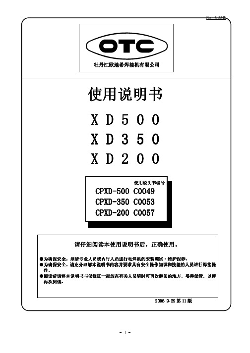
牡丹江欧地希焊接机有限公司目录1. 安全注意事项 (1)2. 敬请遵守的安全事项 (2)3. 使用注意事项 (5)4. 标准配置及附件 (6)5. 各部位名称及功能 (7)6. 必需的电源设备 (9)7. 搬运与设置 (10)8. 连接与安全接地 (11)9. 焊接准备 (15)10. 焊接操作 (17)11. 功能 (22)12. 维护保养及故障修理 (26)13. 零部件一览表 (33)14. 规格 (35)15. 关于售后服务 (37)No. C01851. 安全注意事项● 请在认真阅读本使用说明书后,正确使用。
● 本使用说明书所列注意事项,是为使您能安全使用机器、并使您及他人免受伤害。
● 本焊机设计、制造,虽然充分考虑了安全性,但在使用时,为避免发生重大人身事故,故务请遵守本使用说明书中所列注意事项。
● 错误操作焊机会引发不同等级的伤害、事故。
本使用说明书将危害等级分为3级,用注意标识符及警告用语予以警告,此标识符及警告用语在电焊机中亦表示相同的意思。
·注意标识符表示一般情况。
·上述重大人身事故是指失明、外伤、烫伤(高温、低温)、触电、骨折、中毒等,会遗留后遗症及须长期去医院进行治疗的伤害或死亡。
中度伤害及轻伤,指不必长期住院或长期去医院进行治疗的外伤、烫伤、触电等。
物质损失指涉及财产损失及机器损坏而引发的扩大损失。
另外,在使用机器时,No. C01852.敬请遵守的安全事项No. C0185 2.敬请遵守的安全事项(续)No. C01852.敬请遵守的安全事项(续)No. C01853. 使用注意事项●本焊机的额定负载持续率为 XD200: 200A 50%●例如额定负载持续率50%是指于10分钟之内, 在额定焊接电流下使用5分钟,间歇5分钟 后再进行焊接。
●若超过额定负载持续率标定范围使用,温升超过 允许范围会导致焊机老化、烧损。
●右图所示为XD200焊接电流与负载持续率间的关系。
请按电流值对应的负载持续率在标定 可使用范围内使用。
●因焊枪等气体机器亦限制负载持续率,在一起配套使 用时请按其中额定负载持续率最低的为基准使用。
No. C01854.标准配置及附件4.1标准配置●下图中No. C0185 5. 各部位名称与功能5.1控制面板焊接方法切换开关主电源指示灯Array「检查」位置时送气。
焊接时请设置为「焊接」。
No. C01855. 各部位名称与功能(续)5.1控制面板(续)●CO 2/MAG 模式切换开关5.2 遥控盒●做个别调整时将控制面板的个别/一元切换开关设置为“个别”,分别对焊接电流·焊接电压进行设定。
●做一元化调整时将控制面板的个别/一元切换开关设置为“一元”,只设定焊接电流调整旋钮,焊接电压会被自动设定。
欲对焊接电压进行微调时,请调整微调旋钮。
●当使用CMX (L )-2302以外的送丝机或加长电缆时,刻度与实际焊接电流、电压有时会有出入。
*焊接电流设定旋钮 设定焊接电流。
用您使用焊丝直径的电流刻度设定焊接电流。
按此开关可单独送丝。
可用左侧的焊接电流设定旋钮调节送丝速度。
*点动送丝开关 (一元化微调)旋钮 【个别调整时】 设定焊接电压。
【一元化调整时】 用外侧刻度对应“●”即为标准。
欲调高电压时向“高”、欲调低电压时向“低”设置。
(请做试验性起弧,决定最适合电压值)。
6. 必需的电源设备●焊机在通电起动时电源设备会于一瞬间产生浪涌电流。
其值会依电源内部阻抗而变化。
空气开关(马达用NFB)采用对瞬间过电流动作延迟设计,依据其特性与上述电流关系即使是推荐使用容量的空气开关也有掉闸现象。
若于起动时出现掉闸现象,请将空气开关容量向上提高1个等级。
7. 搬运与设置7.2 设 置●请将其与墙壁或其他焊机间间距保持在30cm 以上。
●避免日光直射、风吹雨淋。
请将其放置在灰尘少且干燥的处所。
●须将其安置在平整的水平处所。
●周围温度为-10~40℃的处所。
(不可结露)●请将其放置在如飞溅等金属异物掉不到焊机内部的处所。
●将其放置在风吹不到电弧的处所(因电弧被风吹到会引起焊接不良,请用挡风板等进行屏蔽。
)危险注意8. 连接与安全接地8.1 焊接电源输出侧连接8.1焊接电源输出侧连接(续)导气接口部件 (请将其于焊接电源的+相连接。
)(型号CMX(L)-2302)遥控盒(置于送丝机上)端子螺栓(请将其于焊接电源的“+”相连接)8.2 遥控盒的安装与连接(2)请用活扳手等将气体连接到连接口并将其紧固。
(3)请将加热器电源电缆连接至加热器专用36V 插座。
加热器专用36V 插座不可做其他用途使用。
(1)连接钢瓶螺母气体钢瓶(2)请将遥控盒电缆由遥控盒托架下穿过与送丝机L 接口连接。
连接后请将电缆纳于机壳内勿使其外露。
(关于拆卸方法请参 照送丝机使用说明书相关内容)(3)加热器用电源电缆遥控盒气体流量计遥控盒侧送丝机侧L接口 气管接口8.4 接地与输入电源侧连接●若使用时不接地电容)① ② ④ ③ ⑤ ⑥ ③⑤ ⑥⑥将焊枪伸直,按下点动开关送丝,于焊丝伸出距焊枪前端约请接入三相380V 电源 请将控制电源开关设定为“ON ” 确认流量调节手柄位于“SHUT ”侧后,打开钢瓶阀门。
请将气体检查开关设定为 “检查”流量调节手柄调节气体流量后,请将气体检查开关恢复为“焊接”遥控盒 点动开关将流量调节手柄向“OPEN ”侧旋转,调节气体流量。
10.1收弧开关的设置与动作●通过设置控制面板的收弧开关可实现无、有、反复3种焊接操作。
(1)收弧开关设置为“无”时●收弧为“无”用于薄板焊接、定位焊、短距反复焊等场合。
●正式焊接时请一直勾住焊枪开关(一直为ON)。
(2)收弧开关设置为“有”时●收弧为“有”时用于焊接结束后填弧坑等用途●正式焊接中松开焊枪开关亦可自保持(ON状态),但在收弧处理时请一直勾住焊枪开关(一直为ON)。
收弧条件,请通过控制面板的收弧电流·电压调节旋钮进行设定。
10. 焊接操作(续)10.2发生异常时或LED2控制面板的电源控制开关“ON”时输入电压频率不稳,异常指示灯亮灯,焊接电源出现停机状态。
此时关闭一下电源控制开关,待输入电压频率稳定后再次给电会解除异常,恢复运转。
2温度异常在超过额定负载持续率、周围温度超过40℃情况下使用时,异常指示灯亮灯,焊机会自动停机。
此时保持通电状态并请等待6分钟左右。
待异常指示灯熄灭后即可使用。
再次焊接时请控制负载持续率并降低使用电流。
No. C0185 10. 焊接操作(续)10.2发生异常时(续)3 输入过电压异常输入电压超过475V时,异常指示灯亮灯,焊机会自动停机。
此时关闭一下电源控制开关,请用万用表测试输入电压确认是否过高。
上述异常原因排除后,再次给电会解除异常。
4 输入电压不足(欠压)异常输入电压低于285V时,异常指示灯亮灯,焊机会自动停机。
此时关闭一下电源控制开关,确认有无异常后请再次给电。
5 焊接方法开关设定异常将控制面板的焊接方法设定为未使用(定义)编号时,异常指示灯闪烁(闪烁1)焊机进入停机状态。
此时恢复到正常设置即可解除异常。
6 焊接操作前异常勾住焊枪开关(一直为“ON”状态)同时打开电源控制开关时异常指示灯闪烁(闪烁1)焊机进入停机状态。
此时关闭一下焊枪开关,即可解除异常。
7 检气异常控制面板的检气开关被设置为「检查」且时间超过2分钟时,异常指示灯闪烁(闪烁1)焊机进入停机状态。
此时将检气开关设置为「焊接」即可解除异常。
8 输出过电流异常于焊接时过电流或短路时间超过2秒时,异常指示灯亮灯,焊机会自动停机。
此时请切断电源确认焊接电流是否超过额定输出电流或确认导电嘴是否与工件相接触,输出电缆是否短路等输出侧短路现象。
排除上述异常原因后,再次开启控制电源开关即可解除异常。
9 微处理器异常内置微处理器出现异常时异常指示灯闪烁(闪烁2)焊机会自动停机。
10 输出异常焊接时焊枪开关“OFF”状态仍有电压输出,异常指示灯闪烁(闪烁2)焊机会自动停机。
此时关闭一下电源控制开关,请用万用表测试主可控硅,确认是否故障。
上述异常原因排除后,再次给电会解除异常。
11 电流检测异常拔掉霍尔元件(CT)与线路板 (P.C.B.1) 间配线时,异常指示灯闪烁(闪烁2)焊机会自动停机。
此时关闭一下电源控制开关,确认配线有无异常。
上述原因排除后,再次给电会解除异常。
No. C018510. 焊接操作(续)10.3 CO2焊接条件(供参考)10.3.1横角焊缝焊接条件例10.3.3 I形对接焊接条件例(无衬垫)No. C018510. 焊接操作(续)10.3 CO 2焊接条件(供参考) 10.3.4重叠角焊缝焊接条件例10.4 MAG 短弧焊接条件表(供参考)材 质:低碳钢瞄准位置No. C018511.功能11.1设定内置切换开关●于焊接电源内部的线路板K5374P00(下面称P.C.B.1)上置有多位开关,调整此开关可进行功能选择。
* 请勿做上述内容以外的变更。
No. C018511. 功能(续)11.1.1起始电流功能●用于收弧功能相同条件,开始焊接。
●产品出厂时起始电流功能设定为「无」。
●使用起始电流功能时,请将线路板P.C.B.1的多位开关(S1)的“2”设为“ON ”。
使用起始电流功能时为“ON ”●使用起始电流功能时,请将控制面板的收弧切换开关设为「有」或「反复」。
此开关设为「无」时不起作用。
-11.1.2预热功能●产品出厂时,预热功能设定为「有」。
若不使用加热器用AC36V 插座时,将其设定为「无」 会提高节能效果。
(预热功能设定为「有」时插座会有AC36V 电压。
设定为「无」时因开关类的连动关系仍有AC36V 电压。
另外,“CO 2/MAG ”模式时,预热功能设定为「无」在不触动任何开关的情况下,经过6分钟后风机会自动停止转动。
)使用预热功能时为“ON ”No. C018511. 功能(续)11.1.3 送丝机功能切换●请配合所使用送丝机设定多位开关。
●使用CMX (L )-2301送丝机时按下图所示请将线路板的CN1,CN3由A →B 。
CMX (L )-2302时 CMX(L)-2301时No. C0185 11.功能(续)11.2 变更提前送气时间●出厂时提前送气时间被设置为0.05秒。
将线路板P.C.B.1的R13(出厂时标准位置=逆时针0点位置)电位器顺时针方向旋转可调节提前送气时间。
右图所示为电位器位置与提前送气时间的关系。
11.2.1 变更滞后停气时间●出厂时滞后停气时间被设置为0.4秒。
将线路板P.C.B.1的R14 (出厂时标准位置=逆时针0点位置)电位器顺时针方向旋转可调节滞后停气时间。
右图所示为电位器位置与滞后停气时间的关系。