SFL950 T8 18W DEMO Design Report v1.1
W800 QFLASH布局说明说明书

WM_W800_QFLASH布局说明V1.1北京联盛德微电子有限责任公司(winner micro)地址:北京市海淀区阜成路67号银都大厦18层电话:+86-10-62161900公司网址:文档修改记录版本修订时间修订记录作者审核V0.1 2019/9/25 [C]创建文档CuiycV0.2 2020/7/8 统一字体CuiycV1.0 2020/8/10 升级版本号CuiycV1.1 2021/2/23 更新用户区位置,与SDK保持一致Cuiyc目录文档修改记录 (2)目录 (3)1引言 (5)1.1编写目的 (5)1.2预期读者 (5)1.3术语定义 (5)1.4参考资料 (5)2W800 QFLASH的布局 (6)2.1QFLASH大于2M的布局 (6)2.1.1物理层参数区 (6)2.1.2SECBOOT参数区 (7)2.1.3SECBOOT 存放区 (8)2.1.4升级IMG存放区 (8)2.1.5运行IMG参数区 (9)2.1.6运行IMG存放区 (10)2.1.7用户参数区 (10)2.1.8系统参数区 (10)2.1.9升级IMG参数区 (11)2.2QFLASH小于2M的布局 (11)3FAQ (14)3.1为什么布局划分总是以64KB为倍数划分? (14)3.2为什么总是留一部分升级区在内部Flash里? (14)1引言1.1编写目的本文档主要用于阐述W800中的QFLASH布局,使读者了解当前W800的QFLASH的使用情况。
1.2预期读者该文档适用的读者包括研发人员、测试人员、W800的工程使用人员等。
1.3术语定义序号术语/缩略语说明/定义1 QFLASH W800 internel Quad-SPI FLASH2 IMG IMAGE3 RF Radio Frequency4 MAC Media Access Control5 SECBOOT Second Boot6 ROM Read-Only Memory7 UPD Image Upgrade Area8 MB Mega Byte9 KB Kilo Byte1.4参考资料无2 W800 QFLASH 的布局地址空间:0x8000000-0x8XFFFFF ,共(X+1)MB ,X >= 1,针对2M 及以上的QFLASH 。
IC 规格书
TDA8927
• High efficiency (>94%) • Operating voltage from ±15 to ±30 V • Very low quiescent current • High output power • Short-circuit proof across the load, only in combination with controller TDA8929T • Diagnostic output • Usable as a stereo Single-Ended (SE) amplifier or as a mono amplifier in Bridge-Tied Load (BTL) • Electrostatic discharge protection (pin to pin) • Thermally protected, only in combination with controller TDA8929T. 2 APPLICATIONS
2001 Dec 11
2
Philips Semiconductors
Objective specification
Power stage 2 × 80 W class-D audio amplifier
1 FEATURES • Multimedia systems • All mains fed audio systems • Car audio (boosters). 3 GENERAL DESCRIPTION
MGW138
TDA8927J TDA8927ST
EN1 SW1 REL1 STAB DIAG POWERUP 4 1 2 9 3 15 CONTROL AND HANDSHAKE
Altronix ACMCB系列输出功率分发与交流电源转换器说明书

DescriptionAltronix ACMCB series distribute and switch power to access control systems and accessories. They convert a 115VAC, 60Hz input into eight (8) independently con-trolled 12VDC or 24VDC Class 2 Rated power-limited PTC protected outputs. Outputs are activated by an open collector sink or normally open (NO) dry trigger input from an Access Control System, Card Reader, Keypad, Push Button, PIR, etc. Units will route power to a variety of access control hardware devices including: Mag Locks, Electric Strikes, Magnetic Door Holders, etc. Outputs will operate in both Fail-Safe and/or Fail-Secure modes. The FACP Interface enables Emergency Egress, Alarm Monitoring, or may be used to trigger other auxiliary devices. The fire alarm discon-nect feature is individually selectable for any or all of the eight (8) outputs.- Eight (8) independently controlled Fail-Safe and/or Fail-Secure power outputs.- Class 2 Rated power-limited PTC Protected Outputs (auto-resettable).- Eight (8) auxiliary power outputs (unswitched).-- Filtered and electronically regulated outputs.- Supervision:- AC Fail- Battery Fail and Battery Presence.- Fire Alarm disconnect (latching or non-latching) is individually selectable for any or all of the eight (8) outputs.- Alarm output relay indicates that FACP input is triggered.- Fire Alarm disconnect input options:a) Normally open (NO) or normally closed (NC) dry contact inputb) Polarity reversal input from FACP signaling circuit.- Built-in charger for sealed lead acid or gel type batteries.- Instantaneous transfer to stand-by batteries.- UL Listed in the U.S. and Canada.- Lifetime Warranty / Made in the U.S.A.ACMCB SeriesPower Supply/Chargers withMulti-Output Access Power ControllersACMCB Series Power Supply Configuration Reference Chart Rev. ULACMCB - 03192020Key FeaturesAL600ULACMCBAltronix Model Number 115VAC 60HzInputCurrent Draw12VDCTotalOutputCurrent24VDCTotalOutputCurrentClass 2RatedPTCProtectedOutputs(auto-resettable)IndividualOutputRatingPower SupplyBoard InputFuse RatingPower SupplyBoard BatteryFuse RatingBatteriesAccommodated byEnclosureAL400ULACMCB3.5A4A3A8 2.5A 5A/250V15A/32VUp to two (2) 12AH / 12VDCAL400ULACMCBJ Up to two (2) 18AH / 12VDCAL600ULACMCB3.5A6A6A–Up to two (2) 12AH / 12VDCAL600ULACMCBJ Up to two (2) 18AH / 12VDCAL1012ULACMCB2.6A10A–15A/32V Up to two (2) 12AH / 12VDCAL1012ULACMCBJ Up to two (2) 18AH / 12VDCAL1024ULACMCB4.2A–10A 6.3A/250V Up to two (2) 12AH / 12VDCAL1024ULACMCBJ Up to two (2) 18AH / 12VDCInputVolt a ge 115VAC, 60Hz.Input FuseVaries, see Reference Chart.OutputsClass 2 Rated power-limited PTC Protected Outputs (auto-resettable). Voltage 12VDC or 24VDC, see Reference Chart. Current Varies, depending on the model. Protection PTC 2.5A. Auxili a ry 3.5A (unswitched). Other Overvoltage protection. Filtered and regulated outputs.Back-up Battery (not included) Capacity 12AH / 12VDC (1 or 2 within enclosure). 18AH / 12VDC (requires larger “J” enclosure). 40 AH / 65 AH (requires separate enclosure). Type Sealed lead acid or gel type. Fuse Rating 15A @ 32VDCAL600ULACMCB(J) does not have a battery fuse. F a iloverUpon AC loss, instantaneous.Fire Alarm Disconnect Latching or non-latching, individually selectable for any or all of the eight (8) outputs.Supervision AC Failure Form “C” contacts (rated 1A @ 28VDC). B a ttery Form “C” contacts (rated 1A @ 28VDC).Indicators (LED) Input 115VAC is present. DC Output Powered.B a ttery Discharged or not connected.Rel a ys Individual LEDs indicate outputs aretriggered (relays energized).FACPIndicates FACP disconnect is triggered.Agency Listings All Models: UL:UL294 Access Control System Units. cUL:CSA C22.2 No.205 Signal Equipment.AL400ULACMCB(J), AL600ULACMCB(J) only: CSFM California State Fire Marshall Approved.Physical and EnvironmentalEnclosure Dimensions (H x W x D)AL400ULACMCB, AL600ULACMCB, AL1012ULACMCB, and AL1024ULACMCB:15.5” x 12” x 4.5” (393.7mm x 304.8mm x 114.3mm). AL400ULACMCBJ, AL600ULACMCBJ, AL1012ULACMCBJ, and AL1024ULACMCBJ:18” x 14.5” x 4.625” (457.2mm x 368.3mm x 117.48mm). Product Weight / Shipping (approx.)Model Product Weight Shipping Weight AL400ULACMCB 10.7 lbs. (4.85 kg)12 lbs. (5.44 kg)AL400ULACMCBJ 14 lbs. (6.35 kg)15 lbs. (6.8 kg)AL600ULACMCB 10.3 lbs. (4.67 kg)11.6 lbs. (5.26 kg)AL600ULACMCBJ 14.85 lbs. (6.74 kg)17.1 lbs. (7.76 kg)AL1012ULACMCB 10.7 lbs. (4.85 kg)12 lbs. (5.44 kg)AL1012ULACMCBJ 14.1 lbs. (6.40 kg)15 lbs. (6.80 kg)AL1024ULACMCB 11.75 lbs. (5.33 kg)13.05 lbs. (5.92 kg)AL1024ULACMCBJ 14.9 lbs. (6.76 kg)16.1 lbs. (7.3 kg) Temper a ture Oper a ting 0ºC to 49ºC (32ºF to 120ºF). Stor a ge -20ºC to 70ºC (-4ºF to 158ºF). Relative Humidity 85% +/-5%. BTU/Hr. (approx.):Model 12VDC BTU/Hr.24VDC BTU/Hr.AL400ULACMCB(J)2537AL600ULACMCB(J)3774AL1012ULACMCB(J)61N/A AL1024ULACMCB(J)N/A 123SpecificationsACMCB SeriesPower Supply/Chargers withMulti-Output Access Power Controllers。
B18系列产品说明书

*(XXX)CO
4
MC/AC
4
1/2" [13] & 3/4" [19]
Attaches to 1/8" [3] through 1/4" [6] flange.
4
1" [25]
4
MC/AC
4
1/2" [13] & 3/4" [19]
other purpose.
NOTE: All load ratings are for static conditions and do not account for dynamic loading such as wind, water or seismic loads, unless otherwise noted.
Pentair, CADDY, ERICO CADWELD, ERICO CRITEC, ERICO, ERIFLEX, and LENTON are owned by Pentair or its global affiliates. All other trademarks are the property of their respective owners. Pentair reserves the right to change specifications without prior notice.
CADDY B18 series with threaded rod going through both
the B18 and the box, this single support is appropriate.
Microsoft System Center 2022 数据中心管理系统说明书
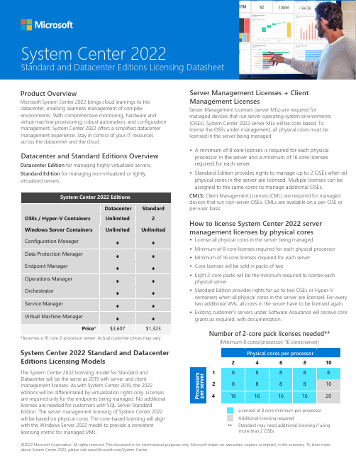
©2022 Microsoft Corporation. All rights reserved. This document is for informational purposes only. Microsoft makes no warranties, express or implied, in this summary. To learn more about System Center 2022, please visit /System-CenterProduct OverviewMicrosoft System Center 2022 brings cloud learnings to the datacenter, enabling seamless management of complexenvironments. With comprehensive monitoring, hardware and virtual machine provisioning, robust automation, and configuration management, System Center 2022 offers a simplified datacenter management experience. Stay in control of your IT resources across the datacenter and the cloud.Datacenter and Standard Editions OverviewDatacenter Edition for managing highly virtualized servers. Standard Edition for managing non-virtualized or lightly virtualized servers.System Center 2022 EditionsDatacenter StandardOSEs / Hyper-V Containers Unlimited 2 Windows Server Containers UnlimitedUnlimitedConfiguration Manager • • Data Protection Manager • • Endpoint Manager • • Operations Manager • • Orchestrator • • Service Manager • • Virtual Machine Manager••Price *$3,607$1,323*Assumes a 16 core 2-processor server. Actual customer prices may vary.System Center 2022 Standard and Datacenter Editions Licensing ModelsThe System Center 2022 licensing model for Standard and Datacenter will be the same as 2019 with server and client management licenses. As with System Center 2019, the 2022editions will be differentiated by virtualization rights only. Licenses are required only for the endpoints being managed. No additional licenses are needed for customers with SQL Server StandardEdition. The server management licensing of System Center 2022 will be based on physical cores. The core-based licensing will align with the Windows Server 2022 model to provide a consistent licensing metric for managed VMs.Server Management Licenses + Client Management LicensesServer Management Licenses (server MLs) are required formanaged devices that run server operating system environments (OSEs). System Center 2022 server MLs will be core based. To license the OSEs under management, all physical cores must be licensed in the server being managed.• A minimum of 8 core licenses is required for each physical processor in the server and a minimum of 16 core licenses required for each server.• Standard Edition provides rights to manage up to 2 OSEs when all physical cores in the server are licensed. Multiple licenses can be assigned to the same cores to manage additional OSEs.CMLS : Client Management Licenses (CML) are required for managed devices that run non-server OSEs. CMLs are available on a per-OSE or per-user basis.How to license System Center 2022 server management licenses by physical cores• License all physical cores in the server being managed • Minimum of 8 core licenses required for each physical processor• Minimum of 16 core licenses required for each server • Core licenses will be sold in packs of two• Eight 2-core packs will be the minimum required to license eachphysical server.• Standard Edition provides rights for up to two OSEs or Hyper-Vcontainers when all physical cores in the server are licensed. For every two additional VMs, all cores in the server have to be licensed again. • Existing customer’s servers under Software Assurance will receive coregrants as required, with documentation.Number of 2-core pack licenses needed**(Minimum 8 cores/processor; 16 cores/server)Physical cores per processor24 6 8 101 8 8 8 8 8 28 8 8 8 10 41616161620Licensed at 8 core minimum per processor Additional licensing required**System Center 2022Standard and Datacenter Editions Licensing DatasheetStandard may need additional licensing if using more than 2 OSEs。
活力安防产品Q950系列硬件说明书
Intercom CameraHardware ManualQ9502017/04/17Table of ContentsPrecautions 3 Safety Instructions (5)Introduction 6The List of Models (6)Package Contents (7)Physical Description (8)Mounting Solutions (10)Installing the Camera 11Step 1: Prepare for Installation (11)Step 2: Route and Connect the Camera Cable (11)Step 3: Mount the Camera (12)Step 4: Connect to the Network (12)Step 5: Access the Camera Live View (12)Cable Connections 13Connecting a Power Adapter (Optional) (13)Connecting DO Devices (Optional) (14)Connecting Audio Output Device (Optional) (14)Connecting Serial Devices (Optional) (15)Other Accessories 16How to Install / Remove the Memory Card (16)How to Remove the Memory Card (16)Accessing the Camera 17Configure the IP Addresses (17)Access the Camera (21)PrecautionsRead these instructionsRead all the safety and operating instructions before using this product.Heed all warningsAdhere to all the warnings on the product and in the instruction manual. Failure to follow the safety instructions given may directly endanger people, cause damage to the system or to other equipment.ServicingDo not attempt to service this product yourself as opening or removing covers may expose you to dangerous voltage or other hazards. Refer all servicing to qualified service personnel.TrademarksACTi and ACTi logo are registered trademarks of ACTi Corporation. All other names and products used in this manual are registered trademarks of their respective companies.LiabilityEvery reasonable care has been taken during the writing of this manual. Please inform your local office if you find any inaccuracies or omissions. ACTi will not be held responsible for any typographical or technical errors and reserves the right to make changes to the product and manuals without prior notice.Federal Communications Commission StatementThis equipment has been tested and found to comply with the limits for aclass B digital device, pursuant to Part 15 of the FCC Rules. These limits aredesigned to provide reasonable protection against harmful interference in a residential installation. This equipment generates, uses, and can radiate radio frequency energy and, if not installed and used in accordance with the instructions, may cause harmful interference to radio communications. However, there is no guarantee that interference will not occur in a particular installation. If this equipment does cause harmful interference to radio or television reception, which can be determined by turning the equipment off and on, the user is encouraged to try to correct the interference by one or more of the following measures: ∙Reorient or relocate the receiving antenna.∙Increase the separation between the equipment and receiver.∙Connect the equipment into an outlet on a circuit different from that to which the receiver is connected.∙Consult the dealer or an experienced radio/TV technician for help.Warning: Changes or modifications to the equipment that are not expressly approved by the responsible party for compliance could void the user’s authority to operate the equipment.European Community Compliance StatementThis product has been tested and found to comply with the limits for Class BInformation Technology Equipment according to European Standard EN 55022 and EN 55024. In a domestic environment, this product may cause radio interference in which cause the user may be required to take adequate measures.Safety InstructionsCleaningDisconnect this product from the power supply before cleaning.Accessories and Repair PartsUse only the accessories and repair parts recommended by the manufacturer. Using other attachments not recommended by the manufacturer may cause hazards.InstallationInstall other devices (such as PoE injector, alarm, etc.) that will be used with the camera in a dry place protected from weather.ServicingDo not attempt to service this product yourself. Refer all servicing to qualified service personnel.Damage Requiring serviceDisconnect this product from the power supply immediately and refer servicing to qualified service personnel under the following conditions.1)When the power-supply cord or plug is damaged2)If liquid has been spilled, or objects have fallen into the product.3)If the inner parts of product have been directly exposed to rain or water.4)If the product does not operate normally even by following the operating instructions in thismanual. Adjust only those controls that are covered by the instruction manual, as improper adjustment of other controls may result in damage, and will often require extensive work by a qualified technician to restore the product to its normal operation.Safety CheckUpon completion of any service or repairs to this product, ask the service technician to perform safety checks to determine if the product is in proper operating condition.IntroductionThe List of ModelsThis hardware manual contains the following models:6MP Door Station Outdoor Intercom with D/N, IR, Extreme WDR,SLLS, Fixed lensPackage ContentsCheck if the camera package comes with the following items.Physical DescriptionMounting SolutionsThere are several mounting options that you can use to install the camera. Select the most suitable solution for your installation environment.NOTE:For more information about the mounting solutions and accessories, please check the Mounting Accessory Selector in our website (/mountingselector).Installing the CameraThis section describes the procedures in mounting the camera on a flat surface, such as wall by the doorway, with the use of the bundled mounting plate. This installation requires access to the back of the surface.NOTE: The following pictures are for reference only.Step 1: Prepare for Installation1.Attach the bundled drill template sticker on the target installation surface.2.Drill the screw holes and cable hole, as needed.3.Remove the drill template.ing the bundled hex screw driver, remove the two hex screws on the bottom of thecamera to separate the mounting plate from the camera.5.Install the mounting plate on the wall using the four bundled screws and plugs.Step 2: Route and Connect the Camera Cable1.Open the back cover.2.Cut the tip of the rubber gland and insert the network cable through the gland.3.Connect the network cable to the connector on the camera.4.Repeat steps 2 and 3 to insert other cables, like power or relay input / output devices, asneeded.e the terminal blocks to connect other devices to the camera. See mapping table onCable Connections on page 13.6.Close the back cover.Step 3: Mount the Camera1.Mount the camera into the mounting plate.2.Then secure the two (2) screws on the bottom side of the plate.Step 4: Connect to the Network1.Connect the other end of the network cable from the camera to the network. Connect allother devices, if any.2.Connect the other end to a switch or injector. Then, connect the switch or injector to anetwork or PC and a power source. See Power-over-Ethernet (PoE) example connection diagram below.PoE Injector / PoE Switch Power CableEthernet CableCameraIn case of using a non-PoE switch, power up the camera using a power adapter (not supplied). See Connecting a Power Adapter (Optional) on page 13 for moreinformation.3.As needed, connect and power up other devices, such as digital input/output, audio, orserial device. See Cable Connections on page13 for more information on connecting other devices.Step 5: Access the Camera Live ViewSee Accessing the Camera on page 17 for more information.Cable ConnectionsThis section describes the procedures in preparing the external devices that you can connect to the camera. The camera supports DC12V power input, Digital Output, Serial devices, and Output using the bundled terminal blocks. The use of these devices, however, is optional.Connecting a Power Adapter (Optional)The camera can be powered by a Power over Ethernet (PoE) switch that is IEEE802.3af compliant. In case of using a non-PoE switch or your PoE switch has limited power supply, you can purchase a power adapter and directly connect the camera to a power outlet. The power adapter must be connected to the supplied terminal block before use.Map the pins of the power adapter to the terminal block pins. Press and hold the orange tab as you insert the wire through the pin slot, then release the orange tab to secure the wire. Then connect the terminal block to the camera.Take note that a standard power adapter cable has two (2) different wires:Connects to GND PinWhite stripe: Connects to 12V PinSet the prepared power adapter for connection later. Below is an example of a power adapter with an attached terminal block.NOTE: The power adapter is not bundled in the package.Connecting DO Devices (Optional)Depending on your surveillance needs, you may connect digital output devices, such as a door relay, to the camera.Map the pins of the digital output device to the terminal block pins accordingly. Press and hold the orange tab as you insert the wire through the pin slot, then release the orange tab to secure the wire. Then connect the terminal block to the camera.The table below shows the DI/DO connection specifications:Connecting Audio Output Device (Optional)Depending on the application, an external speaker may be connected to the camera if the built-in speaker is not enough. You can use either the built-in or the external speaker at one time.By default, the camera is configured to use the built-in speaker. To use an external speaker, adjust the audio switch in the camera connector compartment.Press and hold the orange tab as you insert the wire through the pin slot, then release the orange tab to secure the wire. Then connect the terminal block to the camera.Connecting Serial Devices (Optional)Depending on your needs, you may connect a serial device to the camera using the RS-422 or RS-485 protocol.To connect a serial device, map the pins. Press and hold the orange tab as you insert the wire through the pin slot, then release the orange tab to secure the wire. Then connect the terminal block to the camera.Via RS-485 ConnectionVia RS-422 ConnectionNOTE: The pins of the serial device may be labeled differently depending on the location or country where the device is purchased. For example, some devices may have RS-485 DATA+pins labeled as “TX+”, “RX+”, "A” or “485+”, etc. Refer to the device documentation or contact the manufacturer to verify the corresponding pin labels and ensure properwiring connection.CAUTION: Incorrect wiring may cause damage to the connected devices.DISCLAIMER: ACTi will not be responsible for any damage caused by improper wiring.Other AccessoriesHow to Install / Remove the Memory CardThe camera supports local video recording to a memory card (not supplied).NOTE:Supports microSDHC and microSDXC cards.Install the memory card into the memory card slot.Once inserted, make sure to access the camera Web Configurator and “mount” the card to prepare the card for local recording. Refer to the camera Firmware User’s Manual for more information.How to Remove the Memory CardIn case there is a need to remove the card, make sure to access the camera Web Configurator to safely “unmount” the card first (see the camera Firmware User’s Manual for more information). Once unmounted from the firmware, push the card to eject it from the slot.Accessing the CameraConfigure the IP AddressesIn order to be able to communicate with the camera from your PC, both the camera and the PC have to be within the same network segment. In most cases, it means that they both should have very similar IP addresses, where only the last number of the IP address is different from each other. There are 2 different approaches to IP Address management in Local Area Networks – by DHCP Server or Manually.Using DHCP server to assign IP addressesIf you have connected the computer and the camera into the network that has a DHCP server running, then you do not need to configure the IP addresses at all – both the camera and the PC would request a unique IP address from the DHCP server automatically. In such case, the camera will immediately be ready for the access from the PC. The user, however, might not know the IP address of the camera yet. It is necessary to know the IP address of the camera in order to access it using a Web browser.The quickest way to discover the cameras in the network is to use the simplest network search, built in the Windows system – just by pressing the “Network” icon, all the cameras of the local area network will be discovered by Windows, thanks to the UPnP function support of our cameras.In the example below, the camera that has just been connected to the network is successfully found.Double-click the mouse on the camera model name, the default browser of the PC is automatically launched and the IP address of the target camera is already filled in the address bar of the browser.If you work with our cameras regularly, then there is even a better way to discover the cameras in the network– by using IP Utility. The IP Utility is a light software tool that can not only discover the cameras, but also list lots of valuable information, such as IP and MAC addresses, serial numbers, firmware versions, etc, and allows quick configuration of multiple devices at the same time.Search and downloand IP Utility for free from /DownloadCenter.When you launch IP Utility, the list of connected cameras in the network will be shown. See sample illustration below:You can quickly notice the camera model in the list. Click on the IP address to automatically launch the default browser of the PC with the IP address of the target camera already filled in the address bar of the browser.Use the default IP address of the cameraIf there is no DHCP server in the given network, the user may have to manually assign the IP addresses to both the PC and the camera to make sure they are in the same network segment.When the camera is plugged into the network and it does not detect any DHCP services, it will automatically assign itself a default IP:192.168.0.100Whereas the default port number would be 80. In order to access that camera, the IP address of the PC has to be configured to match the network segment of the camera.Manually adjust the IP address of the PCIn the following example, based on Windows 7, we will configure the IP address to192.168.0.99 and set Subnet Mask to 255.255.255.0 by using the steps below:1 23 4Manually adjust the IP addresses of multiple camerasIf there are more than one camera to be used in the same local area network and there is no DHCP server to assign unique IP addresses to each of them, all of the cameras would then have the initial IP address of 192.168.0.100, which is not a proper situation for network devices – all the IP addresses have to be different from each other. The easiest way to assign cameras the IP addresses is by using IP Utility:With the procedure shown above, all the cameras will have unique IP addresses, starting from 192.168.0.101. In case there are 20 cameras selected, the last one of the cameras would have the IP 192.168.0.120.Later, by pressing the “Refresh”button of the IP Utility, you will be able to see the list of cameras with their new IP addresses.Please note that it is also possible to change the IP addresses manually by using the Web browser. In such case, please plug in only one camera at a time, and change its IP address by using the Web browser before plugging in the next one. This way, the Web browser will not be confused about two devices having the same IP address at the same time.Access the CameraNow that the camera and the PC are both having their unique IP addresses and are under the same network segment, it is possible to use the Web browser of the PC to access the camera.You can use any of the browsers to access the camera, however, the full functionality is provided only for Microsoft Internet Explorer.The browser functionality comparison:* When using non-Internet Explorer browsers, free third-party software plug-ins must be installed to the PC first to be able to get the live video feed from the camera:Disclaimer Notice:The camera manufacturer does not guarantee the compatibility of its cameras with VLC player or QuickTime – since these are third party softwares. The third party has the right to modify their utility any time which might affect the compatibility. In such cases, please use Internet Explorer browser instead.When using Internet Explorer browser, the ActiveX control for video stream management will be downloaded from the camera directly – the user just has to accept the use of such control when prompted so. No other third party utilities are required to be installed in such case.The examples in this manual are based on Internet Explorer browser in order to cover all functions of the camera.Assuming that the camera’s IP address is 192.168.0.100, you can access it by opening the Web browser and typing the following address into Web browser’s address bar:http://192.168.0.100Upon successful connection to the camera, the user interface called Web Configurator would appear together with the login page. The HTTP port number was not added behind the IP address since the default HTTP port of the camera is 80, which can be omitted from the address for convenience.Before logging in, you need to know the factory default Account and Password of the camera.Account: AdminPassword: 123456For further operations, please refer to the Firmware User Manual.Copyright © 2017, ACTi Corporation All Rights Reserved7F, No. 1, Alley 20, Lane 407, Sec. 2, Ti-Ding Blvd., Neihu District, Taipei, Taiwan 114, R.O.C.TEL : +886-2-2656-2588 FAX : +886-2-2656-2599Email:**************。
罗克韦尔自动化 CodeMeter 设备规格说明书 (9509-CMSDCD4, 9509-CMST

Technical DataOriginal InstructionsCodeMeter Devices SpecificationsCatalog Numbers 9509-CMSDCD4, 9509-CMSTICKCRockwell Automation® industrial controllers and computers use CodeMeter devices to enable product license activations. FactoryTalk® Activation software 4.00 and later is required to activate the CodeMeter devices.•For Activation Instructions, see FactoryTalk Activation Manager Online Help.•For use with Studio 5000 Logix Designer® and ControlLogix® features, see Studio 5000 Logix Designer Online Help.•For supported firmware, see the Product Compatibility and Download Center at rok.auto/pcdc.Summary of ChangesThis publication contains the following new or updated information. This list includes substantive updates only and is not intended to reflect all changes.Topic PageRecommended FactoryTalk-Supported Device Types2CodeMeter Device Descriptions2Technical Specifications3Environmental Specifications3Certifications3Topic PageRemoved the 9509-CMSTICK8 device ThroughoutUpdated the 9509-USB-DONG2 storage size from 2 GB to 8 GB22Rockwell Automation Publication 9509-TD001B-EN-P - February 2023CodeMeter Devices Specifications Technical DataRecommended FactoryTalk-Supported Device TypesCodeMeter Device DescriptionsType Labels Catalog Number NameStorage CodeMeter CmCard 9509-CMSDCD4CodeMeter CmCard SD4 GBCmStick9509-CMSTICKC CodeMeter CmStick Compact None FlexNetFlexNet, Flexera, HASP, or Flex ID9509-USB-DONG2FlexNet (plug and play)8 GBIMPORTANTIn some cases, product activations require a specific device type. If you see the `Different dongle type needed’ message, the device that you are using is not supported for activating the product. Themessage indicates the type of device that is required. Remove the incorrect device from the computer and insert a device of the correct type.CodeMeter Device Cat. No.Flash Storage DescriptionCmCard SD9509-CMSDCD4 4 GB•Secure Digital (SD) card, use with controllers, SD 2.0, SD 3.0 (UHS-I)•Performance Read seq. up to 24 MB/s, Write seq. up to 23 MB/s •4 GB, single-level cell (SLC), nonvolatile memory for high industrial requirements•Based on High-Performance Security Crypto-ChipCmStick Compact9509-CMSTICKC none•USB stick•Based on High-Performance Security Crypto-ChipRockwell Automation Publication 9509-TD001B-EN-P - February 20233CodeMeter Devices Specifications Technical DataTechnical SpecificationsEnvironmental SpecificationsCertificationsFor CodeMeter certifications, see the following Wibu-Systems data sheets:•9509-CMSDCD4 - 1040-03-106•9509-CMSTICKC - 1001-03-160-9001Attribute 9509-CMSDCD49509-CMSTICKC Memory 4 GBNoneSupported Devices •ControlLogix 5580 controllers•CompactLogix™ 5480 and 5380 controllers •Personal computers •Personal computersWeight, approx 2 g (0.07 oz)CmStick - 6 g (0.21 oz)Cover - 8 g (0.28 oz)Power Supply 2.7...3.6 V Bus-powered, Type. 25 mA 5V Bus-poweredInterfacePersonal computersHi-speed USB 2.0 certified, Mass Storage Communication (MSC)Attribute9509-CMSDCD49509-CMSTICKCTemperature, operating -40…+85 °C (-40…+185 °F)-25…+70 °C (-13…+158 °F)Temperature, storage -40…+100°C (-40…+212 °F)-40…+100°C (-40…+212 °F)Relative humidity 85% RH, 85 °C (185 °F)85% RH, 85 °C (185 °F)Dimensions (HxWxD), Approx 32 x 24 x 2.1 mm (1.26 x 0.94 x 0.08 in.)21 x 14 x 6.5 mm(0.83 x 0.55 x 0.26 in.)Weight 2 g (0.08 oz)CmStick - 6 g (0.24 oz)Cover - 8 g (0.31 oz)Status IndicatorsN/A< 20 mA (status indicators off), < 60 mA (both status indicators on)Publication 9509-TD001B-EN-P - February 2023Supersedes Publication 9509-TD001A-EN-P - December 2016Copyright © 2023 Rockwell Automation, Inc. All rights reserved. Printed in the U.S.A.Additional ResourcesThese documents contain additional information concerning related products from Rockwell Automation. You can view or download publications at rok.auto/literature .Rockwell Automation SupportUse these resources to access support information.Documentation FeedbackYour comments help us serve your documentation needs better. If you have any suggestions on how to improve our content, complete the form at rok.auto/docfeedback .Resource DescriptionIndustrial Automation Wiring and Grounding Guidelines, publication 1770-4.1Provides general guidelines for installing a Rockwell Automation industrial system.Rockwell Automation Product Certifications website, rok.auto/certifications Provides declarations of conformity, certificates, and other certification details.Technical Support CenterFind help with how-to videos, FAQs, chat, user forums, Knowledgebase, and product notification updates.rok.auto/support Local Technical Support Phone Numbers Locate the telephone number for your country.rok.auto/phonesupport Technical Documentation CenterQuickly access and download technical specifications, installation instructions, and user manuals.rok.auto/techdocs Literature LibraryFind installation instructions, manuals, brochures, and technical data publications.rok.auto/literature Product Compatibility and Download Center (PCDC)Download firmware, associated files (such as AOP, EDS, and DTM), and access product release notes.rok.auto/pcdcRockwell Automation maintains current product environmental compliance information on its website at rok.auto/pec .Allen-Bradley, CompactLogix, ControlLogix, FactoryTalk, Rockwell Automation, and Studio 5000 Logix Designer are trademarks of Rockwell Automation, Inc.Trademarks not belonging to Rockwell Automation are property of their respective companies.Rockwell Otomasyon Ticaret A.Ş. Kar Plaza İş Merkezi E Blok Kat:6 34752, İçerenköy, İstanbul, Tel: +90 (216) 5698400 EEE Yönetmeli ğine Uygundur。
萨福铝焊机说明书
B - 安装调试 ............................................................................................................10 1. 拆除包装 .......................................................................................................10 2. 送丝机连接...................................................................................................10 3. 主电源的电路连接 .....................................................................................10 4. 焊枪的连接...................................................................................................10
中文
目录
安全说明 .....................................................................................................................2
A - 总体介绍 ...............................................................................................................7 1. 装置简介 .........................................................................................................7 2. 焊接设备组成 ................................................................................................7 3. 前面板描述.....................................................................................................8 4. 选配件..............................................................................................................8 5. OPTIPULS i / i W技术规格 .............................................................................8 6. 尺寸和重量.....................................................................................................9 7. 冷却装置的技术规格......................................................................................9
- 1、下载文档前请自行甄别文档内容的完整性,平台不提供额外的编辑、内容补充、找答案等附加服务。
- 2、"仅部分预览"的文档,不可在线预览部分如存在完整性等问题,可反馈申请退款(可完整预览的文档不适用该条件!)。
- 3、如文档侵犯您的权益,请联系客服反馈,我们会尽快为您处理(人工客服工作时间:9:00-18:30)。
安规电容
Y1 1nF/275Vac P=10mm
1
32
CBB电容
47nF/400V P=10mm
1
33
电解电容
10uF/50V 105℃ 5*10mm 20%
1
34
电解电容
270uF/50V Lowesr 105℃ 10*20mm 20%
2
35
IC
SFL950 SOT23-6 赛威
1
36
MOSFET
PPT 模 板 下 载 : w w w /moba n/ 节 日 PPT 模 板 : w w w /jieri/ PPT 背 景 图 片 : w w w /beijing / 优 秀 PPT 下 载 : w w w /xia za i/ Word教程: /word/ 资 料 下 载 : w w w /zilia o/ 范 文 下 载 : w w w /fa nw en/ 教 案 下 载 : w w w /jia oa n/
安全
产品电性详述
描述 Vi Fi Ii
Vout Iout Pout
Vripple
Efficiency
最小 90 47 0.92 30 417
85
典型 50/60
最大
264 63 0.3
10 42 430 443 18
180
EN55015 EN55015 EN60950
单位
VAC Hz A PF %
V
名称 贴片电容 贴片电容 贴片电容 贴片电阻 贴片电阻 贴片电阻 贴片电阻
贴片电阻
贴片电阻 贴片电阻 贴片电阻
贴片电阻 贴片电阻 贴片电阻 贴片电阻 贴片电阻 贴片电阻 贴片电阻 插件二极管 插件二极管 插件二极管
BOM 清单
规格 2.2nF/1000V 1206 X7R 10%
1uF/25V 0805 X7R 10% 470pF/250V 1206 X7R 10%
OR 1206 5% 33K 1206 5% 1N4007 DO-41 1000V1A FR107 DO-41 1000V1A HER304 DO-201AD 300V3A
数量 1 1 1 2 2 1 1
1
1 3 2
2 1 1 1 1 1 1 5 1 1
位号
C2 C4 C7
R1 R2 R3 R4 R8 R20
9
变压器绕法
原理图 1
初级
28Ts
3 8Ts
4 5 反馈 6Ts 2
6 14Ts 次级
7
磁芯用0.16mm 镀锡线接2脚
S1
电性规格书: 1. 电感量1-4=0.5mH±8% @1KHz 0.25V 2. 漏感 <25uH @10KHz 0.25V 3. 耐压测试= 3.75KV 5mA 1Min
POUT (W) 13.17 14.42 15.66 16.93 18.14 13.14 14.42 15.66 16.89 18.10 13.59 14.85 16.09 17.36 18.56 13.71 14.98 16.27 17.51 18.73
效率 (%) 86.02 85.83 85.53 85.24 84.78 87.62 87.67 87.65 87.49 87.26 88.72 89.04 89.27 89.43 89.62 88.28 88.65 89.05 89.26 89.50
变压器注意事项 1、变压器设计时反射电压Vro按照100V 计算,占空比 ≤ 50% 设计。 2、变压器磁芯用裸铜线接地。
16
联系我们
赛威科技网站: 销售和FAE: sales@
赛威科技深圳商务中心:
深圳市南山区科技园高新南一道 创维大厦C座802室 Tel: 0755-26942291 Fax: 0755-26942403
230V/50Hz FULL LOAD传导N线
14 14
EMI (辐射)
230V/50Hz FULL LOAD 辐射 垂直方向 测试标准EN55015
15
230V/50Hz FULL LOAD 辐射 水平方向
应用指导
PCB Layout 注意事项 1、PCB Layout时地线尽可能短,IC的地和变压器的地分开接地。 2、控制电路上所有的地先连起来然后一起连到输入滤波电容的地。 3、DEM上下偏电阻要靠近DEM脚,可以降低噪音耦合。 4、VDD 脚的电容要尽量靠近VDD脚,得到好的去耦效果。 5、COMP电容尽量靠近芯片放置。
1、外驱MOS管 ,SOT23-6封装,全电压输入最大输出功率50W。 2、PSR控制模式,无光耦,无431。 3、±4% 的输出恒流精度。 4、专利的‘Super-PFC/PSRTM ’技术。 5、专利的‘Min -THDTM ’技术 6、逐周期电流限制,内置前沿消隐。 7、内置90KHz铅频,EMI 性能良好。 8、系统效率达到 85% 以上。 9、内置软启动,超低启动电流,管脚浮空保护。
2
25
工字电感
26
共模电感
27
共模电感
8*10mm 2.0mH
1
EE13 0.2mm 95Ts 30mH Min
1
T8*6*3 7Ts 47uH Min
1
28
压敏电阻
07D471K
1
29
安规电容
30
安规电容
X2 47nF/275Vac P=10mm
1
X2 100nF/275Vac P=10mm
1
31
5.6k 0805 5% 2M 1206 5%
470K 1206 5% 2.2R 0805 5%
150R 1206 5%
10K 0805 5% 22R 1206 5% 220K 1206 5%
2.2R 1206 1% 2.4R 1206 1% 100R 0805 1% 91K 0805 1% 15K 0805 1%
FQPF5N60C 5A/600V TO-220F FAIRCHILD
1
37
变压器
EDR2809 5+2 LP=500uH ±8%
1
38
PCB板
FR-4 260mm*18mm T=1.0mm
1
元件总数 50PCS
D7 F1
L1 L2 L3 LF1 LF2
MOV1 CX1 CX2 CY1 C1 C2 C6 C8 C9 U1 Q1 T1
R9
R10 R11 R12 R21 R22 R13 R14
R15 R16 R17 R18 R19 R24 R23 D1 D2 D3 D4 D6 D5 D8
备注
8
BOM 清单
22
贴片二极管
1N4148 75V 0.15A SOD-23
1
23
玻璃管保险管
2A/250V 4*10mm
1
24
工字电感
6*8mm 1.0mH
输出短路 平均效率 满载PF值
THD
(W)
η (%)
(%)
0.26
85.48
0.991
3.3
0.29
87.54
0.994
5.5
0.43
89.22
0.964
7.8
0.48
88.95
0.947
9.0
注:以上测试数据在裸板条件下
7
序号 1 2 3 4 5 6 7
8
9 10 11
12 13 14 15 16 17 18 19 20 21
2UEW 0.23mmx1P 14Ts – 初级 (顺绕) 一层密绕
2UEW 0.23mmx1P 14Ts – 初级 (顺绕) 一层密绕
EDR2809骨架槽宽 4.0mm
10
5PIN
2Ts Tape
4PIN
2Ts Tape
2Ts Tape
2Ts Tape
关键波形
90V/60Hz AC FULL LOAD开机启动时间 2.2S 264V/50Hz AC FULL LOAD开机启动时间 720mS
120
270
370
输出电压 (CV) 30.00 33.00 36.00 39.00 42.00 30.00 33.00 36.00 39.00 42.00 30.00 33.00 36.00 39.00 42.00 30.00 33.00 36.00 39.00 42.00
输出电流 (A) 0.439 0.437 0.435 0.434 0.432 0.438 0.437 0.435 0.433 0.431 0.453 0.450 0.447 0.445 0.442 0.457 0.454 0.452 0.449 0.446
10、输出OVP,OLP,VDD过压,欠压及钳位保护,LED短路/开路保护。
2
SFL950 IC 应用领域
1、LED 灯管,射灯,筒灯,球泡灯,吸顶灯等等。
3
Description 输入电压 输入频率 输入电流 PF值 THD
输出CV模式 输出电流 输出功率
输出纹波电流
效率
传导(EMI) 辐射(EMI)
+10uF电解电容
PCB 板端 VIN = 115VAC a Nhomakorabead%
230VAC
CV= 42V (TA = 25 ℃)
4
电路原理图
5
PCBA 图
PCBA 尺寸 长260x宽18x高10mm
6
基本性能测试数据
输入电压 (V)
90/60Hz
115/60Hz
230/50Hz
264/50Hz
待机 (mW) 90
行 业 PPT 模 板 : w w w /ha ng y e/ PPT 素 材 下 载 : w w w /suca i/ PPT 图 表 下 载 : w w w /tubia o/ PPT教程: /powerpoint/ E xcel教 程 : w w w /excel/ PPT 课 件 下 载 : w w w /k ejia n/ 试 卷 下 载 : w w w /shiti/