RTU-485-台达通迅模块说明书
台达PLC使用问题集

台达PLC使用问题集1、现有5台台达的变频器放在同一个控制柜中,想用PLC的485来控制,请问应该使用什么样的通讯线缆和连接件,主要是台达变频的那个电话插头怎样和另外的变频器互相连接?答:使用屏蔽电缆,注意台达RS485需要使用100欧姆左右的终端电阻。
那个电话插头应该是RJ11。
2、我一直在用的都是台达-ES/EX/SS系列的PLC .最近有一台多年前的PLC 需要修改程序,但是忘了当年设置的密码,有谁能告诉我有什么要的办法吗?否则只能更换一台PLC 了。
答:强制M1069 ON即可解除。
但6.0及以上韧体屏蔽了这一个功能。
3、如何实现TP04G的韧体更新?答:1)、关闭HMI电源;2)、打开HMI机壳后盖3)、将更新韧体制具插入插空上4)、然后给HMI加电源,此时,HMI画面为暗。
5)、用FLash软件就可以对HMI进行韧体的更新了。
4、现有一个系统,用DVP-ES带485通讯口的。
现用485通讯口和百特仪表通讯。
用编程口挂GPRS模块,进行联网。
中央监控室需要下位机定期传送数据和事件触发功能,问如何能实现?如果不能,其它系列PLC能实现吗?答:台达PLC自带两个通讯口,1个RS232通讯口(COM1,即8PIN的编程口)1个RS485通讯口(COM2),COM1只能工作在从站模式下,不能发数据,COM2可以工作在主从两种模式下,可以发数据。
所以台达所有PLC,都不能实现!5、上位机和台达的PLC通讯怎么设置成主从式通讯?用其自带的485口?答:上位机和台达的PLC通讯,多数上位机是主的。
这个不用什么设置,台达PLC默认就是从站,不需要做任何设置,直接调用MODBUS协议就可以了。
但我们默认的是ASCII,如果要用RTU,必须把M1143置ON。
6、想往变频器里写频率有固定的地址,例如:H2001,要是想通过文本显示器或触摸屏改变变频器里其他的参数如加速时间,那么是否可以象改变写入频率一样,只要知道其地址就可以直接通过触摸屏改变其参数值的大小了吗?答:当然可以,对应台达M系列变频器,参数P10的地址为000AH,对应B系列,第一加速时间地址为010AH7、台达ES的PLC,内建485口可以通讯人机吗?答:完全可以8、EX用485与上位机通讯(ASCⅡ模式),D1120需要设置吗?答:看什么格式,如果是9600/7/E1就不用设置,其余的要。
Omni-Ultra-485 产品说明书

ContentsI NTRODUCTION (1)O VERVIEW (1)W HAT’S I NCLUDED (1)F ACTORY D EFAULT S ETTINGS (1)C ARD S ETUP (2)A DDRESS S ELECTION (2)IRQ S ELECTION (3)I NTERRUPT M ODES (4)RS-485 E NABLE M ODES (5)C ONNECTOR P IN A SSIGNMENTS (7)EIA-530 (7)SIO-485 (8)L INE T ERMINATION (9)I NSTALLATION (10)W INDOWS 3.X (I NCLUDING WFW 3.11) I NSTALLATION (10)W INDOWS 95 AND W INDOWS NT I NSTALLATION (12)OMG-U LTRA-485 S OFTWARE D RIVERS (12)T ECHNICAL D ESCRIPTION (13)F EATURES (13)S PECIFICATIONS (14)E NVIRONMENTAL S PECIFICATIONS (14)M ANUFACTURING (14)P OWER C ONSUMPTION (14)M EAN T IME B ETWEEN F AILURES (MTBF) (14)P HYSICAL D IMENSIONS (14)A PPENDIX A - T ROUBLESHOOTING (15)A PPENDIX B - H OW T O G ET A SSISTANCE (17)A PPENDIX C - E LECTRICAL I NTERFACE (18)RS-530 (18)RS-422 (18)RS-485 (18)A PPENDIX D - A SYNCHRONOUS C OMMUNICATIONS (20)A PPENDIX E - S ILK-S CREEN (21)A PPENDIX F - C OMPLIANCE N OTICES (22)F EDERAL C OMMUNICATIONS C OMMISSION S TATEMENT (22)EMC D IRECTIVE S TATEMENT (22)W ARRANTY (23)FiguresFigure 1 - Header E1, IRQ Selection (3)Figure 2 - Header E2, Normal IRQ Mode (4)Figure 3 - Header E2, Shared IRQ Mode (4)Figure 4 - Header E5 RS-485 Transmit Mode (5)Figure 5 - Header E3 RS-485 Receive Mode (6)Figure 6 - Dip-shunt E4 (EIA-530 Mode) (7)Figure 7 - Dip-shunt E4 (SIO-485 Mode) (8)Figure 8 – SW2, Line Termination (9)Figure 9 - Asynchronous Communications Bit Diagram (20)© 1997b Omega Engineering, Incorporated. All rights reserved.IntroductionIntroductionOverviewThe Omega Engineering OMG-Ultra-485 provides the PC with an additional RS-422/485 serial port for terminals, modems, printers, etc What’s IncludedThe OMG-Ultra-485 is shipped with the following items. If any of these items are missing or damaged, contact the supplier.•OMG-Ultra-485 Serial I/O Adapter• 3.5″ Serial Utility Diskette•User ManualFactory Default SettingsThe OMG-Ultra-485 factory default settings are as follows:Port #Base Address IRQ Electrical SpecificationPort 13F84RS-485 ‘Auto’To install the OMG-Ultra-485 using factory default settings, refer to Installation on page 10.For your reference, record installed OMG-Ultra-485 settings below: Port #Base Address IRQ Electrical SpecificationOmega Engineering OMG-Ultra-485Page 1Card SetupCard SetupThe OMG-Ultra-485 contains several jumper straps which must be set for proper operation.Address SelectionThe OMG-Ultra-485occupies 8 consecutive I/O locations, and looks to the PC as a standard serial port. A DIP-switch (SW1) is used to set the port address options for the OMG-Ultra-485. Be careful when selecting the port addresses as some selections may conflict with existing ports. The following table shows the addressing options available with the standard PAL. If different address options are required, please contact Omega Engineering Technical Support about a custom PAL option.Port1 J2SW1-1SW1-2SW1-3SW1-4 Disabled On On On On3F8On On On Off2F8On On Off On3E8On On Off Off2E8On Off On On3220On Off On Off3228On Off Off On4220On Off Off Off4228Off On On On238Off On On Off300Off On Off On308Off On Off Off280Off Off On On288Off Off On Off290Off Off Off On298Off Off Off Off Note: Each COM port in the system should have a unique address. Typically COM1: - COM4: addresses are 3F8, 2F8, 3E8 & 2E8 Hex.Omega Engineering OMG-Ultra-485Page 2Card SetupOmega Engineering OMG-Ultra-485Page 3IRQ SelectionHeader E1 selects the interrupt request for each serial port. If COM1: is selected, the corresponding jumper must be on the IRQ4 setting. If COM2: is selected, the corresponding jumper must be on IRQ3.Note : Most communications software applications default COM3: to IRQ4and COM4: to IRQ3. This requires the sharing of interrupts between COM1: and COM3:, and between COM2: and COM4:.While this is the default, it is not always the preferred setting.Check your software configuration instructions to determine the most appropriate IRQ selection .Figure 1 - Header E1, IRQ SelectionAny two or more ports can share a common IRQ by placing the jumpers on the same IRQ setting at header E1 and setting the appropriate selections at E2. Consult your particular software for IRQ selection. If no interrupt is desired, remove the jumper.2345710111215E1Card SetupOmega Engineering OMG-Ultra-485Page 4Interrupt ModesHeader E2 selects the interrupt mode for the OMG-Ultra-485.‘N ’ indicates the (N )ormal, single interrupt per port mode. ‘S ’ Indicates the (S )hared interrupt mode, which allows more than one port to access a single IRQ. Any two or more ports can share a common IRQ by placing the jumpers on the same IRQ setting and setting the appropriate selections at E1. Consult your particular software for IRQ selection. If no interrupt is desired, remove the jumper. ‘M ’ indicates the inclusion of a 1K ohm pull-down resistor required on one port when sharing interrupts.Figure 2 - Header E2, Normal IRQ ModeSet the jumper to ‘S ’ if you are using more than one OMG-Ultra-485 in a bus or to completely remove the pull-down resistor for hardware compatibility. Setting the adapter in this configuration when it is not accompanied by a pull-down resistor will prevent the ports from triggering an interrupt .Set the jumpers to ‘S ’ for shared interrupt mode on all blocks sharing an IRQ except one. Set that port block for ‘M ’. This provides the pull-down resistor circuit that makes sharing IRQs possible. If you are using more than one OMG-Ultra-485 or a compatible adapter in a bus you should only have one port set to ‘M ’. The following example shows two OMG-Ultra-485adapters sharing a single IRQ.Figure 3 - Header E2, Shared IRQ ModeCard Setup RS-485 Enable ModesRS-485 is ideal for multi-drop or network environments. RS-485 requires a tri-state driver (not dual-state) that will allow the electrical presence of the driver to be removed from the line. The driver is in a tri-state or high impedance condition when this occurs. Only one driver may be active at a time and the other driver(s) must be tri-stated. The output modem control signal R equest T o S end (RTS) is typically used to control the state of the driver. Some communication software packages refer to RS-485 as RTS enable or RTS block mode transfer.One of the unique features of the OMG-Ultra-485 is the ability to be RS-485 compatible without the need for special software or drivers. This ability is especially useful in Windows, Windows NT, and OS/2 environments where the lower level I/O control is abstracted from the application program. This ability means that the user can effectively use the OMG-Ultra-485 in a RS-485 application with existing (i.e. standard RS-232) software drivers.Header E5 is used to control the RS-485 mode functions for the transmitter circuit. The selections are ‘RTS’ enable, ‘Auto’ enable, or ‘422’ which means always enabled. The ‘Auto’ enable feature automatically enables/disables the RS-485 transmitter circuit. The ‘RTS’mode uses the ‘RTS’ modem control signal to enable the RS-485 transmitter circuit and provides backward compatibility with existing software products. The ‘422’ mode allows the port to be used in a point to point RS-422 application where the tri-stating of the transmitter circuit is not required.Note: The jumper in the above example is in the ‘422’ position. This is the only setting in which the modem control outputs (RTS, DTR) are valid.Omega Engineering OMG-Ultra-485Page 5Card Setup Figure 4 - Header E5 RS-485 Transmit ModeHeader E3 is used to control the RS-485 enable/disable functions for the receiver circuit. The RS-485 ‘Echo’ is the result of connecting the receiver inputs to the transmitter outputs. Every time a character is transmitted, it is also received. This can be beneficial if the software can handle echoing (i.e. using received characters to throttle the transmitter) or it can confuse the system if the software does not. The selection at E3 should follow the selection made at E5 if ‘No Echo’ is desired. If Echo suppression is not desired then leave the jumper in the ‘422’ position. Also note, the modem control inputs (DSR, DCD, CTS) are only valid when Header E3 is in the 422 mode. These header blocks are described in the illustration and table that follow.Figure 5 - Header E3 RS-485 Receive ModeOmega Engineering OMG-Ultra-485Page 6Card SetupOmega Engineering OMG-Ultra-485Page 7Connector Pin Assignments EIA-530DIP-shunt E4 selects the pin out for the DB-25 connector P3. With the 5position shunt in the EIA-530 mode, the ULTRA-485 complies with the EIA-530 pin out with the following signals supported:EIA-530E4SIO-485Figure 6 - Dip-shunt E4 (EIA-530 Mode)Signal Name Pin #Mode GND Ground 7RDB RX+Receive Positive 16Input RDA RX-Receive Negative 3Input CTSB CTS+Clear To Send Positive 13Input CTSA CTS-Clear To Send Negative 5Input DSRB DSR+Data Set Ready Positive 22Input DSRA DSR-Data Set Ready Negative 6Input DCDB DCD+Data Carrier Detect Positive 10Input DCDA DCD-Data Carrier Detect Negative8Input TDB TX+Transmit Positive 14Output TDA TX-Transmit Negative 2Output RTSB RTS+Request To Send Positive 19Output RTSA RTS-Request To Send Negative 4Output DTRB DTR+Data Terminal. Ready Positive 23Output DTRADTR-Data Terminal Ready Negative20OutputCard SetupOmega Engineering OMG-Ultra-485Page 8SIO-485With the 5 position shunt in the SIO-485 mode, the OMG-Ultra-485 is compatible with the Omega Engineering SIO-485 (part# 3054) with the following signals supported:EIA-530SIO-485Figure 7 - Dip-shunt E4 (SIO-485 Mode)/Signal Name Pin #Mode GND Ground7TDB TX+Transmit Positive 24Output TDA TX-Transmit Negative 25Output RDB RX+Receive Positive 12Input RDARX-Receive Negative 13InputCard Setup Line TerminationTypically, each end of the RS-485 bus must have line terminating resistors (RS-422 terminates at the receive end only). A 100 ohm resistor is across each RS-530/422/485 input in addition to a 1K ohm pull-up/pull-down combination that bias the receiver inputs. DIP-switch SW2 provides the ability to customize this interface to system requirements. Each switch position corresponds to a specific portion of the interface. If multiple OMG-Ultra-485adapters are configured in a RS-485 network, only the boards on each end should have switches T, P & P ON. Refer to the following table for each position’s operation:Name FunctionT Adds or removes the 120 ohm termination.P Adds or removes the 1K ohm pull-down resistor in the RS-422/RS-485 receiver circuit (Receive data only).P Adds or removes the 1K ohm pull-up resistor in the RS-422/RS-485 receiver circuit (Receive data only).L Connects the TX+ to RX+ for RS-485 two wire operation.L Connects the TX- to RX- for RS-485 two wire operation.T P P L LFigure 8 – SW2, Line TerminationOmega Engineering OMG-Ultra-485Page 9Installation Omega Engineering OMG-Ultra-485Page 10InstallationThe OMG-Ultra-485 can be installed in any of the PC expansion slots.The OMG-Ultra-485 contains several jumper straps for each port which must be set for proper operation.1. Turn off PC power. Disconnect the power cord.2. Remove the PC case cover.3. Locate an available slot and remove the blank metal slot cover.4. Gently insert the OMG-Ultra-485 into the slot. Make sure that theadapter is seated properly.5. Replace the screw.6. Replace the cover.7. Connect the power cord.Installation is complete.Windows 3.x (Including WFW 3.11) InstallationTo configure the OMG-Ultra-485 under Windows 3.x start by opening the ‘Control Panel ’. The Control Panel is typically found in the ‘Main ’Program Group. The next step is to open the ‘Ports ’ selection under the ‘Control Panel’.Manufacturing•IPC 610-A Class-III standards are adhered to with a 0.1 visual A.Q.L.and 100% Functional Testing.•All Omega Engineering Printed Circuit boards are built to U.L. 94V0 rating and are 100% electrically tested. These printed circuit boards are solder mask over bare copper or solder mask over tin nickel. Power ConsumptionSupply line+5 VDCRating160 mAMean Time Between Failures (MTBF)Greater than 150,000 hours. (Calculated)Physical DimensionsBoard length 5.0 inches(12.70 cm) Board Height including Goldfingers 4.2 inches(10.66 cm) Board Height excluding Goldfingers 3.9 inches(9.91 cm)Figure 9 - Asynchronous Communications Bit DiagramThis special bit is called the parity bit. Parity is a simple method of determining if a data bit has been lost or corrupted during transmission. There are several methods for implementing a parity check to guard against data corruption. Common methods are called (E)ven Parity or (O)dd Parity. Sometimes parity is not used to detect errors on the data stream. This is refereed to as (N)o parity. Because each bit in asynchronous communications is sent consecutively, it is easy to generalize asynchronous communications by stating that each character is wrapped (framed) by pre-defined bits to mark the beginning and end of the serial transmission of the character. The data rate and communication parameters for asynchronous communications have to be the same at both the transmitting and receiving ends. The communication parameters are baud rate, parity, number of data bits per character, and stop bits (i.e. 9600,N,8,1).3.9"5.0"4.2"Appendix F - Compliance Notices Omega Engineering OMG-Ultra-485Page 22Appendix F - Compliance NoticesFederal Communications Commission StatementFCC - This equipment has been tested and found to comply with the limits for Class A digital device, pursuant to Part 15 of the FCC Rules. These limits are designed to provide reasonable protection against harmful interference when the equipment is operated in a commercial environment. This equipment generates, uses, and can radiate radio frequency energy and, if not installed and used in accordance with the instruction manual, may cause harmful interference to radio communications. Operation of this equipment in a residential area is likely to cause harmful interference in such case the user will be required to correct the interference at his own expense.EMC Directive StatementProducts bearing the CE Label fulfill therequirements of the EMC directive (89/336/EEC)and of the low-voltage directive (73/23/EEC) issuedby the European Commission.To obey these directives, the following European standards must be met:•EN55022 Class A - “Limits and methods of measurement ofradio interference characteristics of information technology equipment”•EN50082-1 - “Electromagnetic compatibility - Generic immunity standard” Part 1 : Residential, commercial and light industry•EN60950 (IEC950) - “Safety of information technologyequipment, including electrical business equipment”WarningThis is a Class A Product. In a domestic environment this product may cause radio interference in which case the user may be required to take adequate measures.Always use cabling provided with this product if possible. If no cable is provided or if an alternate cable is required, use high quality shielded cabling to maintain compliance with FCC/EMC directives.WarrantyWarrantyOmega Engineering, Inc. warrants this product to be in good working order for a period of one year from the date of purchase. Should this product fail to be in good working order at any time during this period, Omega Engineering will, at it's option, replace or repair it at no additional charge except as set forth in the following terms. This warranty does not apply to products damaged by misuse, modifications, accident or disaster.Omega Engineering assumes no liability for any damages, lost profits, lost savings or any other incidental or consequential damage resulting from the use, misuse of, or inability to use this product. Omega Engineering will not be liable for any claim made by any other related party.RETURN AUTHORIZATION MUST BE OBTAINED FROM OMEGA ENGINEERING BEFORE RETURNED MERCHANDISE WILL BE ACCEPTED. AUTHORIZATION CAN BE OBTAINED BY CALLING OMEGA ENGINEERING AND REQUESTING A RETURN MERCHANDISE AUTHORIZATION (RMA) NUMBER.Omega Engineering, IncorporatedOne Omega DrivePO Box 4047Stamford, CT 06907(800)826-6342FAX: (203)359-7990email:*************Technical Support is available from 8 a.m. to 5 p.m. Eastern time.Monday - FridayTrademarksOmega Engineering, Incorporated acknowledges that all trademarks referenced in this manual are the service mark, trademark, or registered trademark of the respective company.OMG-Ultra-485 is a trademark of Omega Engineering, Incorporated. Omega Engineering OMG-Ultra-485Page 23。
温腾HMI与多个Modbus RTU(RS-485)从机设备通信指南说明书

Weintek USA, Inc. Rev. JAN 27, 2020(425) 488-1100Weintek HMI to Multiple Modbus RTU (RS-485) Slave DevicesIntroduction: This instruction manual discusses how to communicate with Modbus RTU slave devices through a RS-485 network. The Modbus RTU protocol is widely used on many industrial sites and adopted by many manufacturers because this protocol is free, open, and simple. Modbus RTU enables master-slave communication between devices connected through serial RS-485 using two-wires. In a RS-485 network, a master queries one or more slave devices for data acquisition or parameter settings. The slaves return a response to all queries addressed to them individually and only respond to the queries transmitted from the master. Typically, a Modbus RS-485 communication network requires a 120 ohm resistor at each physical end of a network. That means there should be a resister at the master and the last slave. The terminating resistor should match the characteristic impedance of the cable being terminated.RS-485 Wiring DiagramEquipment & Software:1.EasyBuilder Pro v6.03.02.2942.Weintek HMI cMT30903.Modbus RTU (RS-485) slave devicesKnowledge of Modbus RTU Protocol:A Modbus slave device provides a Modbus master device with the following memory tables to access data.The supported Modbus Function Codes vary from the manufacturers. The common function codes are shown below.A Modbus map is a list of parameters stored in Modbus addresses. It provides the essential information for users to access data. Most slave devices are built with fixed map defined by the manufacturer. While some Modbus slave devices, such as PLCs or HMIs, allow programmers to configure custom maps. You will need to know the following information defined by your devices.•What is the unit ID of the device? (fixed or configurable?)•Where is data stored? (which tables and addresses)•How is data stored? (data types and byte, word ordering)•How do you find the range?Prerequisites:•Each Modbus RTU slave device must use the same serial configuration, including Baud rate, Data bits, Stop bits, and Parity.•Each Modbus RTU slave devices must be assigned a unique slave ID number (unit address) from 1 to 247.These settings should be configurable by software of your Modbus devices.Detail of the HMI Programming:Open a new project and choose the HMI model cMT3090. To get the HMI talking to the Modbus slaves, go to the [HOME] tab on the top of the menu and then click on the [System Parameters] button.You will need to select one of the drivers based on the specification of your devices.In this case, the Modbus RTU(Zero-based Addressing) driver is used.I/F: RS-485 2WDevice default station no.: You can enter the station number of the first slave device.Click on the [Settings..] button to enter the serial settings of your Modbus slave devices, including Baud rate, Data bits, Stop bits, and Parity.Click on the [Data Conversion] button to implement Byte swap, Word swap, or Double Word swap.•Each character, such as “A”, represents one byte.•AB->BA does a byte swap.•ABCD->CDAB does a word swap.•You can do a byte swap and word swap with 3x_Double and 4x_Double.•ABCDEFGH->EFGHABCD does a double word swap (for CMT HMIs only).•You can do a byte swap, word swap, and double word swap with 3x_QWord4x_QWord (for CMT HMIs only).Since the Modbus protocol does not define exactly how data is stored in the registers. You will need to check with the manufacturer to find out which ordering format your slave device stores data.By default the Modbus RTU master driver in Weintek HMI uses Low byte (or word, double word) first as ordering.Accessible device memory in EasyBuilder ProThe Weintek HMI uses the following Modbus Function Codes.*1. The Modbus RTU(Zero-based Addressing) driver reads a group of 16 bits at a time. Bit groups are 0-15, 16-31, 32-47,48-63, etc. All bits in the group must be available in the controller for the HMI to read. Otherwise, errors will result.*2. The 5x is exactly the same as the 4x. Use the 5x when reading/writing to a 32-bit registers using the low word first format. For example,4x contains the following data,Then use 5x instead of 4x, it will be*3. By default the Weintek HMI uses a Function Code 16 to write multiple registers, even if it is only writing to one register. The 6x forces the HMI to transmit a Function Code 06 to write a single register.Special device memory in EasyBuilder ProHow to read/write 32-bit unsigned dataTo read 32-bit unsinged data from register40106 (combined with 40107 to generate 32-bit data) with high word first format, please check the Word swap[ABCD ->CDAB] option on [Data Conversion].Create a Numeric object and specify the address 4x_Double - 106 on the [General] tab as below.Under the [Format] tab, enter the number of digits used in this parameter as well as the device’s low limit and high limit. Click the [OK] button to finish setting up this object.Place the Numeric object onto the editing area.How to read/write bits in the 4x/3x memory tablesThe 4x_Bit is used to read/write to individual bits in the 4x memory table. To access a bit in 4x memory table, select the 4x_Bit as the address for bit-type objects such as Bit Lamp. Under the Address, use the format DDDDDdd to enter the word memory area, followed by the two-digit bit reference.For example, to monitor the second bit of 40030, enter "3001" into the Address. (DD=30, dd=01)The 3x_Bit works the same as for the 4x_Bit, except that it is used for accessing bits in a 3x memory table (input register, read only).How to read data on the different station numberThe address format of station number is ABC#AddrThe ABC stands for device station number and ranges from 0 to 255.The Addr stands for device address. T he “#” is a sign that separates the station number and the address.To read the station number 2 and address 0, input 2# as prefix.Once finishing the input, the HMI will read address 0 in the 3x (The 3xxxx table) Modbus table using Function Code 0x04.If you input the address without a station number, the HMI will query the default slave device. (where you set up on the Modbus RTU driver)How to use Station Number VariableStation Number Variable allows you to change the station number (unit ID) during runtime to monitor different slaves. Up to 16 Station Number Variables can be used in one project.The address format of Station Number Variables is var{i}#AddrThe i can be a constant value from 0 to 15.The Addr stands for the device address. T he “#” is a sign that separates the station number and the address.In this example, the station number is determined by var1. You will need to enter a station number to System Register LW-10001.A Number object specified the address of the Modbus slaveThe other Number object specified System Register LW-10001When you input the constant value 3 to the Numeric object that is specified address LW-10001 during runtime, the other Numeric object will display thevalue pulled out from the slave ID 3.Founded in 1996, WEINTEK LABS is a global-leading HMI manufacturer and is dedicated to the development, design, and manufacturing of practical HMI solutions. WEINTEK LAB’s mission is to provide quality, customizable HMI-solutions that meet the needs of all industrial automation requirements while maintaining customer satisfaction by prov iding “on-demand” customer service. WEINTEK LABS brought their innovative technology to the United States in 2016, WEINTEK USA, INC., to provide quality and expedient solutions to the North American industrial market.6219 NE 181s Street STE 120Kenmore, WA 98028425-488-1100。
台达485说明书

memory card. There is a switch on it and PLC will check the state of this
DVP-256FM/
switch when PLC is power on. If this switch is Off, memory card will be
less than 30mA (Inputting update time of current value of digital value output.
negative current is banned)
DVP-256FM(for EH2 series)/DVP-512FM(for EH3 series) is a data backup
N2
D+
Resistor
120Ω
DN1 N2
There are two built-in analog knobs VR0 and VR1 in a
DVP-EH2 series MPU. You can expand the analog input
VR2 VR3
knobs VR2~VR7 by using DVP-F6VR. Refer to API85 VRRD and API86 VRSC in the application manual (programming) for more detail.
8 CTS+
9 CTS-
MODE 1: RS-232 MODE 2: RS-422
CO M2/DB- 9 MODE 3: RS-485
For EH3 MPU, it will be COM3 card and either slave or master mode can
台达变频器参数设置台达变频器参数设置台达变频器参数...
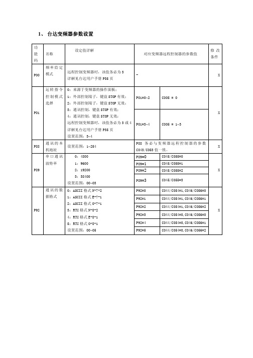
1、台达变频器参数设置功能码 名称设定值详解对应变频器远程控制器的参数值修改条件P00 频率给定模式远程控制变频器时,该值务必为3详解见台达用户手册P35页- XP01=0~2 C005 = 0P01 运转指令控制模式选择0:来源于变频器的操作面板;1:外部控制端子,键盘STOP有效;2:外部控制端子,键盘STOP无效;3:通讯控制,键盘STOP有效;4:通讯控制,键盘STOP无效;远程控制变频器时,该值务必为3或4详解见台达用户手册P35页设置范围:3~4P01=3~4 C005 = 1~3XP88 通讯的本机地址设置范围:1~254P88务必与变频器远程控制器的参数C043/C053值一致。
XP89=0 C045/C055=0P89=1 C045/C055=1P89=2 C045/C055=2P89 串口通讯波特率0:48001:96002:192003:38400设置范围:00~03P89=3 C045/C055=3XP92=0 C044/C054=1,C046/C056=0P92=1 C044/C054=1,C046/C056=1P92=2 C044/C054=1,C046/C056=2P92=3 C044/C054=0,C046/C056=0P92=4 C044/C054=0,C046/C056=1P92 通讯的数据格式0:ASCII格式N-7-21:ASCII格式E-7-12:ASCII格式O-7-13:RTU格式N-8-24:RTU格式E-8-15:RTU格式O-8-1设置范围:00~05 P92=5 C044/C054=0,C046/C056=2X功能码 名称 设定值详解对应变频器远程控制器的参数值修改条件F111 设定频率上限建议最大输出频率的值设为和远程控制器的C023参数的值相同。
默认为50Hz设置范围:0~400HzF111 = C023F004=0~1 C005 = 0F200 启动给定方式选择0:来源于变频器的操作面板;1:外部控制端子;远程控制变频器时,该值可为二者中的一个设置范围:0~1 F004=2 C005 = 1~3XF204 主频率来源远程控制变频器时,该值务必为:5由上位机给定F204务必为5 XF900 本机地址 设置范围:1~247 F900务必与变频器远程控制器的参数C043/C053值一致。
台达温度控制器 DTA系列手册
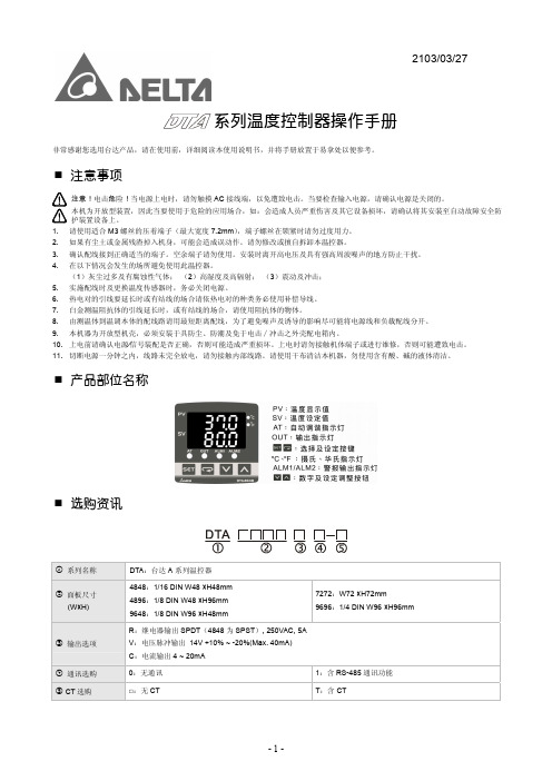
显示刻度 控制方法
控制输出种类
采样周期 耐震动 耐冲击 操作环境温度 存放环境温度 操作高度 操作环境湿度 面板防护等级
交流电 100 ~ 240V, 50/60Hz
额定电压 85% ~110%
5VA Max.
七段 LED 显示; 目前温度值:红色,设定温度值:绿色
热电偶对:K, J, T, E, N, R, S, B, U, L, Txk
0 ~ 600°C -20.0 ~ 400.0°C
-200 ~ 400°C -20.0 ~ 400.0°C
-100 ~ 850°C -20.0 ~ 500.0°C -200 ~ 1,300°C
-200 ~ 850°C -200 ~ 500°C -200 ~ 800°C
设定值 PV SV
未接温度传感器
按V
按V
选择加热⁄冷却
按V
或
设定热⁄冷控制周期
(PID 控制时设定)
按V
按键锁定功能
按V
警报 1 模式设定
按V
测量温度误差调整
输出量显示及调整
警报 2 模式设定
按V
按V
按V
20mA 输出误差调整 (电流输出时显示)
有 CT 功能时,当有 OUT 输出显示目 前 OUT 电流值
ASCII, RTU 通讯格式选择
CONTROL:选择控制方式,ON/OFF(
)或 PID( )或手动调整(
)
SWITCH:加热 (
)冷却(
)选择
AL1 SET:警报一模式设定(请参阅「警报输出」说明)
AL2 SET:警报二模式设定(请参阅「警报输出」说明)
C SELECT: ASCII, RTU 通讯格式选择
(完整版)485终端机操作指南(新开普)

485终端机操作指南VER 2.2浙江正元智慧科技有限公司二OO七年六月公司简介浙江正元智慧科技有限公司成立于1994年,注册资金3000万元,是一家集智能卡应用开发、设备制造和系统集成于一体的专业公司,是浙江省知名的IT 企业,在省内是金卡工程领域的龙头企业,系统集成居于前列。
公司现有员工二百多名,是信息产业部认定的软件企业,浙江省唯一的“校园智能卡应用技术研究发展中心” ,是浙江省科技厅认定的高新技术企业,拥有国家信息产业部计算机信息系统集成二级资质和国家建设部建筑智能化工程专业承包二级资质,通过了美国CMU/SE的软件CMM级评估,通过了银行卡检测中心的检测,取得IS09001质量体系认证,并被中国人民银行浙江省分行连续五年授予AAA言用等级企业。
公司拥有直接用户近两千家,浙江省绝大部分高校和中学的校园一卡通均由我公司实施,我公司参与了杭州市民卡工程,承接了中国最高楼——上海环球金融大厦的楼宇一卡通及安防系统项目,研发并推广了解放军“士兵卡管理系统”。
此外,公司还研发了“行政执法IC卡管理系统”、“文明卡管理系统”、“海量数据处理平台” 、“数字档案馆系统”等多行业的应用系统。
浙江正元智慧科技有限公司着力研发、推广IC卡技术在教育及其它行业的应用,拥有自主研发的软、硬件产品三十余种,部分主导产品曾获部级科技成果一等奖。
公司研发的“数字化园区一卡通”系统作为未来数字化园区环境下的一项基础工程,由一卡通数据中心、卡应用支撑平台、卡业务管理和卡应用系统等四个部分组成,具有安全性高、性能优越、扩展能力强等特点,包含商务收费系统、机房管理系统、门禁管理系统、考勤管理系统等15个子系统。
公司拥有自主生产的各类系统终端设备:射频IC/ID 卡的消费终端、智能控制器、门禁控制器、考勤终端、通用读卡器、智能控水器、智能控电柜、电开水器等系列产品。
公司在发展中形成了独特的经营理念和管理风格,一直把“正合奇胜,积贤培元;诚信为本,做人为先”作为公司基本理念,注重“知识分子革命化,革命分子知识化”培养,把科学化管理与军事化管理相结合,严谨缜密的科学作风与充满激情的战斗作风相融合。
RTU中文说明书(精品)

1用户手册2目录1前言................................................................................................................................32产品介绍.. (4)2.1如何使用本产品 (4)2.2产品技术参数.............................................................................................................43产品硬件说明....................................................................................................................53.1产品尺寸....................................................................................................................53.2LED 指示灯说明.........................................................................................................53.3接线端子说明.............................................................................................................64使用配置软件对RTU 参数设置. (8)4.1进入配置模式.............................................................................................................84.2基本参数设置 (10)4.2.1设置报警/控制号码.................................................................................................104.2.2基本参数设置........................................................................................................104.2.3报警参数设置........................................................................................................124.2.4所有短信...............................................................................................................144.2.5系列权限...............................................................................................................144.3输入输出设置...........................................................................................................164.3.1设置开关量输入类型...............................................................................................164.3.2设置开关量输出参数...............................................................................................174.3.3设置报警/恢复内容.................................................................................................194.3.4输入口参数配置.....................................................................................................194.3.5设置输入口名称.....................................................................................................204.3.6设置输出口名称.....................................................................................................214.3.7开关量权限............................................................................................................224.4AIN 配置.................................................................................................................234.4.1AIN 参数设置........................................................................................................234.4.2AIN 短信..............................................................................................................254.4.3AIN 名称..............................................................................................................254.4.4AIN 权限..............................................................................................................264.5传感器配置...............................................................................................................274.5.1蜂鸣器参数设置.....................................................................................................274.5.2内置温度传感器参数设置(可选功能)......................................................................274.5.3内置电池参数设置(可选功能)...............................................................................284.6其他参数设置...........................................................................................................304.6.1实时联动参数设置..................................................................................................304.6.2定时器设置............................................................................................................314.6.3自定义指令设置.. (31)RTU5011用户手册1前言感谢您使用RTU5011GSM短信报警控制器,阅读本产品说明书能让您快速掌握本产品的功能和使用方法。
- 1、下载文档前请自行甄别文档内容的完整性,平台不提供额外的编辑、内容补充、找答案等附加服务。
- 2、"仅部分预览"的文档,不可在线预览部分如存在完整性等问题,可反馈申请退款(可完整预览的文档不适用该条件!)。
- 3、如文档侵犯您的权益,请联系客服反馈,我们会尽快为您处理(人工客服工作时间:9:00-18:30)。
DVP-PLC 操作手册
1
Modbus 远程 I/O 通讯模块 RTU-485
1 RTU-485 简介
1. 谢谢您使用台达 RTU-485 模块。为了确保能正确地安装及操作本产品,请在使用该模块之前,仔细 阅读该使用手册。
2. RTU-485 为 Modbus 远程 I/O 通讯模块,可实现台达可编程逻辑控制器对 Slim 系列 I/O 模块的远程 控制。
4 功能区域说明 ........................................................................................................................................5 4.1 数字输入/输出模块区域 ...............................................................................................................5 4.2 特殊输入/输出模块区域 ...............................................................................................................6 4.3 特殊功能区域...............................................................................................................................6 4.4 RTU-485 错误代码说明 ...............................................................................................................7
8、O、1
8、N、1
8、N、2
1,200 bps; 2,400 bps; 4,800 bps;9,600 bps;19,200 bps; 38,400 bps; 57,600 bps; 115,200 bps
项目 电源规格
规格 24 VDC (-15% ~ 20%)(具直流输入电源极性反接保护)
பைடு நூலகம்
环境规格
项目
噪声免疫力
操作温度 储存温度 耐振动/冲击 标准
规格 ESD (IEC 61131-2, IEC 61000-4-2): 8KV Air Discharge,4KV Contact Discharge EFT (IEC 61131-2, IEC 61000-4-4): Power Line: 2KV, Digital I/O: 1KV Analog & Communication I/O: 1KV Damped-Oscillatory Wave: Power Line: 1KV, Digital I/O: 1KV RS (IEC 61131-2, IEC 61000-4-3): 80MHz~1000MHz , 1.4GHz~2.0GHz , 10V/m 0ºC ~ 55ºC(温度)、50 ~ 95%(湿度)、污染等级 2
RTU-485
Modbus 远程 I/O 通讯模块 操作手册
DVP-0214010-01
Modbus 远程 I/O 通讯模块 RTU-485
注意事项
3 此操作手册提供功能规格、安装、基本操作与设定,以及有关于网络协议内容的介绍。
3 本机为开放型 (OPEN TYPE) 机壳,因此使用者使用本机时,必须将其安装于具防尘、防潮及免于电击/ 冲击意外的外壳配线箱内。另必须具备保护措施 (如:特殊的工具或钥匙才可打开) ,防止非维护人员操作 或意外冲击本体,造成危险及损坏,且请勿在上电时触摸任何端子。
5 RTU-485 支持的功能码 .........................................................................................................................7 6 RTU-485 应用范例 ...............................................................................................................................7
项目 传输方式 电气隔离 接头 传输电缆
规格 RS-485 500 VDC 可插拔式连接器 (3Pin) 双绞线式隔离线
通讯
项目 通讯模式
串行传输速度 电气规格
规格
7、E、1
7、O、2
8、O、1
ASCII Mode
7、O、1
7、N、2
8、N、1
7、E、2
8、E、1
8、N、2
RTU Mode
8、E、1
6.1 RTU-485 与主控设备连接............................................................................................................7 6.2 应用范例 ......................................................................................................................................8 7 LED 灯指示说明及故障排除 ................................................................................................................10 7.1 POWER 灯显示说明..................................................................................................................10 7.2 RUN LED 灯显示说明................................................................................................................10 7.3 ALARM LED 灯显示说明 ...........................................................................................................10 7.4 RS-485 LED 灯显示说明 ...........................................................................................................10
-25ºC ~ 70ºC(温度)、5 ~ 95%(湿度)
国际标准规范 IEC 61131-2、IEC 68-2-6 (TEST Fc)/IEC 61131-2 & IEC 68-2-27 (TEST Ea)
IEC 61131-2、UL508 标准
2
DVP-PLC 操作手册
3. RTU-485 模块为标准的 Modbus 从站设备,可以相容其他遵循标准 Modbus 协议的主控设备。
1.1 RTU-485 功能简介 z 自动检测 I/O 模块 z 连接特殊输入/输出模块最大数目为 8 台,数字量点数最大扩展 128 点输入和 128 点输出
1.2 功能规格
DeviceNet 连接器
3 请务必仔细阅读本使用手册,并依照本手册指示进行操作,以免造成产品受损,或导致人员受伤。
目录
1 RTU-485 简介 .......................................................................................................................................2 1.1 RTU-485 功能简介 ......................................................................................................................2 1.2 功能规格 ......................................................................................................................................2
2 RTU-485 单元部件 ...............................................................................................................................3 2.1 外观尺寸 ......................................................................................................................................3 2.2 各部介绍 ......................................................................................................................................3 2.3 RUN/STOP 开关..........................................................................................................................3 2.4 地址设定开关...............................................................................................................................4 2.5 通讯设定开关...............................................................................................................................4