The NACA airfoil series
CAtxtAppB

Appendix B Sources of Experimental Datafor Code Validation Airfoil Data SourcesSome sources of airfoil geometry and experimental data for use in code evaluation are listed here. Note that rigorous validation of codes requires very careful analysis, and an understanding of possible experimental, as well as computational, error. See the junior Aerodynamic Lab notes for my comments on the issues involved in aerodynamic testing in wind tunnels. Hardcopies of the NACA reports are located in the Virginia Tech Library at DOCS Y3.N21/5:9 on the first floor.BooksAbbott and von Doenhoff, Theory of Airfoil Sections. Look in the references for the original NACA airfoil reports. Note that pressure distributions are fairly rare. See also NACA R 824.Riegels, Airfoil Sections, Butterworths, London, 1961. (English language version)NASA Low and Medium Speed AirfoilsMcGhee, Robert J., and Beasley, William D., “Low Speed Aerodynamic Characteristics of a 17-Percent-Thick Airfoil Section Designed for General Aviation Applications,” NASA TN D-7428, 1973.McGhee, Robert J., Beasley, William D., and Somers, Dan M., “Low Speed Aerodynamic Characteristics of a 13-Percent-Thick Airfoil Section Designed for General AviationApplications,” NASA TM X-72697, 1975.McGhee, Robert J., and Beasley, William D., “Effects of Thickness on the Aerodynamic Characteristics of an Initial Low-Speed Family of Airfoils for General AviationApplications,” NASA TM X-72843, 1976.McGhee, Robert J., and Beasley, William D., “Low-Speed Wind-Tunnel Results for aModified 13-Percent-Thick Airfoil,” NASA TM X-74018, 1977.Barnwell, Richard W., Noonan, Kevin W., and McGhee, Robert J., “Low SpeedAerodynamic Characteristics of a 16-Percent-Thick Variable Geometry Airfoil Designed for General Aviation Application,” NASA TP-1324, 1978.McGhee, Robert J., and Beasley, William D., “Wind-Tunnel Results for an Improved 21-Percent-Thick Low-Speed Airfoil Section,” NASA TM-78650, 1978.McGhee, Robert J., Beasley, William D., and Whitcomb, Richard T., “NASA Low- and Medium-Speed Airfoil Development “ NASA TM-78709, 1979.McGhee, Robert J., and Beasley, William D., “Low-Speed Aerodynamic Characteristics ofa 13-Percent-Thick Medium Speed Airfoil Designed for General Aviation Applications,”NASA TP-1498, 1979.McGhee, Robert J., and Beasley, William D., “Low Speed Aerodynamic Characteristics of a 17-Percent-Thick Medium Speed Airfoil Designed for General Aviation Applications,”NASA TP-1786, 1980McGhee, Robert J., and Beasley, William D., “Wind-Tunnel Results for a Modified 17-Percent Thick Low-Speed Airfoil Section, “ NASA TP-1919, 1981. (LS(1)-0417mod)Ferris, James D., McGhee, Robert J., and Barnwell, Richard W., “Low Speed Wind-Tunnel Results for Symmetrical NASA LS(1)-0013 Airfoil,” NASA TM-4003, 1987.B-2 Applied Computational AerodynamicsNASA Transonic AirfoilsWhitcomb, “Review of NASA Supercritical Airfoils,” ICAS Paper 74-10, August 1974(ICAS stands for International Council of the Aeronautical Sciences)Harris, C.D., “NASA Supercritical Airfoils,” NASA TP 2969, March 1990. See references contained in this report for sources of experimental data.Laminar Flow AirfoilsSomers, Dan M., “Design and Experimental Results for a Flapped Natural-Laminar-Flow Airfoil for General Aviation Applications,” NASA TP-1865, June 1981. (NLF(1)-0215F, Lancair and Wheeler express airfoil)McGhee, Robert J., Viken, Jeffrey K., and Pfenninger, Werner, D., “Experimental Results fora Flapped Natural-Laminar Flow Airfoil With High Lift/Drag Ratio,” NASA TM-85788,1984.Sewell, W.G., McGhee, R.J., Viken, J.K., Waggoner, E.G., Walker, B.S., and Miller, B.F.,“Wind Tunnel Results for a High-Speed, Natural Laminar Flow Airfoil Designed for General Aviation Aircraft,” NASA TM 87602, No. 1985.Other Low and Medium Speed Airfoils and Airfoil DataBeasley, William D., and McGhee, Robert J., “Experimental and Theoretical Low-Speed Aerodynamic Characteristics of the NACA 65(1)-213, a = 0.50, Airfoil,” NASA TMX-3160, Feb. 1975Hicks, Raymond M., “A Recontoured Upper Surface Designed to Increase the Maximum Lift Coefficient of a Modified NACA 65(0.82) (9.9) Airfoil Section,” NASA TM 85855, Feb.1984.Bingham, Gene J., and Chen, Allen Wen-shin, “Low Speed Aerodynamic Characteristics of an Airfoil Optimized for Maximum Lift Coefficient,” NASA TN D-7071, Dec. 1971.Stivers, “Effects of Subsonic Mach Number on the Forces and Pressure Distributions on Four 64A-Series Airfoil Sections at Angles of Attack as High as 28°,” NACA TN 3162, 1954.Also see TN 2096?Liebeck, R.H., “A Class of Airfoils Designed for High Lift in Incompressible Flow”, Journal of Aircraft, Oct. 1973, Vol. 10, No. 10, pp. 610-617Multi-element Airfoil DataWenzinger, C.J., and Delano, J., “Pressure Distribution Over an NACA 23012 Airfoil with a Slotted and Plain Flap,” NACA R-633, 1938.Harris, T.A., and Lowry, J.G., “Pressure Distribution over an NACA 23012 Airfoil with a Fixed Slot and a Slotted Flap,” NACA R 732, 1942.Axelson, J.A., and Stevens, G.L., “Investigation of a Slat in Several Different Positions on an NACA 64A010 Airfoil for a Wide Range of Subsonic Mach Numbers,” NACA TN 3129, March 1954.Weick, F.E., and Shortal, J.A., “The Effect of Multiple Fixed Slots and a Trailing-edge Flap on the Lift and Drag of a Clark Y Airfoil,” NACA R 427, 1932.Wentz, W.H., Jr., and Seetharam, H.C, “Development of a Fowler Flap System for a High Performance General Aviation Airfoil,” NASA CR-2443, 1974Seetharam, H.C., and Wentz, W.H., “Experimental Studies of Flow Separation and Stalling on a Two-Dimensional Airfoil at Low Speeds,” NASA CR-2560, 1975.Appendix B: Data Sources B-3Kelly, John A., and Hayter, N-L, F., “Lift and Pitching Moment at Low Speeds of the NACA 64A010 Airfoil Section Equipped with Various Combinations of Leading Edge Slat, Leading Edge Flap, Split Flap and Double-Slotter Flap,” NACA TN 3007, Sep. 1953. (no drag or pressure distributions)Other data sources:Bertin and Smith, 1st edition , page 102-102, NACA 4412, pressure distribution, 2nd edition: pg 201-202, 3rd edition: pg 221-222 (from Pinkerton, NACA R 563, 1936, but WATCH OUT! This data is not what you might think. See NACA R-646 for true 2-D data!)Hurley, F.X., Spaid, F.W., Roos, F.W., Stivers, L.S., Jr., and Bandettini, A., “Supercritical Airfoil Flowfield Measurements,” AIAA Paper No. 75-880, June 1975.Three-Dimensional Data SourcesElementary body geometries: There were many tests conducted by the NACA using geometries that are simple to model. Similar tests were also done in the early days of NASA. The NACA reports were classified at the time, but have been declassified. A sample of cases I’ve used are included here:Williams, C.V., “An Investigation of the Effects of a Geometric Twist on the Aerodynamic Loading Characteristics of a 45° Sweptback Wing-Body Configuration at Transonic Speeds,”NACA RM L54H18, 1954.Runckel, J.F., and Lee, E.E., Jr., “Investigation of Transonic Speeds of the Loading Over a 45° Sweptback Wing Having an Aspect Ratio of 3, Taper Ratio of 0.2, and NACA 65A004 Airfoil Sections,” NASA TN D-712, 1961.Loving, D.L., and Estabrooks, B.B., “Transonic Wing Investigation in the Langley Eight Foot High Speed Tunnel at High Subsonic Mach Numbers and at a Mach number of 1.2,”NACA RM L51F07, 1951.McDevitt, J.B., “An Experimental Investigation of Two Methods for Reducing Transonic Drag of Swept Wing and Body Combinations,” NACA RMA55B21, April 1955.Keener, E.R., “Pressure Measurements Obtained in Flight at Transonic Speeds for aConically Cambered Delta Wing,” NASA TM X-48, October 1959.The standard transonic test case: the ONERA M6 wing has been used in practically every transonic code validation calculation ever published. The data is contained in AGARD AR-138 cited below.Supercritical Wings:Harris, C.D., and Bartlett, D.W., “Tabulated Pressure Measurements on a NASASupercritical-Wing Research Airplane Model With and Without Fuselage Area-RuleAdditions at Mach 0.25 to 1.00,” NASA TM X-2634, 1972.Harris, C.D., “Wind-Tunnel Measurements of Aerodynamic Load Distribution on a NASA Supercritical-WIng Research Airplane Configuration,” NASA TM X-2469, 1972.Montoya, L.C., and Banner, R.D., “F-8 Supercritical Wing Flight Pressure, Boundary Layer and Wake Measurements and Comparisons with Wind Tunnel Data,” NASA TM X-3544, March 1977.Hinson, B.L., and Burdges, K.P., “Acquisition and Application of Transonic Wing and Far-Field Test Data for Three-Dimensional Computational Method Evaluation,” AFOSR-TR-80-0421, March 1980, available from DTIC as AD A085 258. These are the Lockheed Wings A, B, and C.Keener, E.R., “Pressure Distribution Measurements on a Transonic Low-Aspect RatioWing,” NASA TM 86683, 1985. (this is the so-called Lockheed Wing C)B-4 Applied Computational AerodynamicsKeener, E.R., “Boundary Layer Measurements on a Transonic Low-Aspect Ratio Wing,”NASA TM 88214, 1986. (this is the so-called Lockheed Wing C)Supersonic Wing Data:D.S. Miller,E.J. Landrum, J.C. Townsend, and W.H. Mason, “Pressure and Force Data for aFlat Wing and a Warped Conical Wing Having a Shockless Recompression at Mach 1.62,”NASA TP 1759, April 1981.J.L. Pittman, D.S. Miller, and W.H. Mason, “Fuselage and Canard Effects on an Attached Flow, Maneuver Wing at Mach 1.62,” NASA TP 2249, February 1984J.L. Pittman, D.S. Miller, and W.H. Mason, “Supersonic, Nonlinear, Attached-Flow Wing Design for High Lift with Experimental Validation,” NASA TP 2336, August 1984. AGARD Test CasesAGARD has selected test cases for CFD code validation. These cases are important because an attempt has been made to define the test conditions and any corrections required precisely enough for use in code validation work. This is not an easy job. This also means that the airfoil test coordinates and results are available in tabulated form in these reports. The reports include: AGARD AR-138, “Experimental Data Base for Computer Program Assessment,”May, 1979Two-dimensional test cases:(1) NACA 0012, over a range of subsonic Mach and angle of attack, both force andmoment and pressure distributions,(2) NLR QE 0.11-0.75-1.375, a symmetrical airfoil designed to be shock free at atransonic design point, Mach range from 0.30 to 0.85, all at zero angle of attack,(3) CAST 7, pressure distributions over a range of Mach from 0.40 to 0.80, from -2° to 5°, also boundary layer measurements. No force and moment data;(4) NLR7301, thick supercritical airfoil (16.5%), Mach from 0.30 to 0.85, a from -4°to + 4°, pressure, and force and moment;(5) SKF 1.1/with maneuver flap, (French), Mach number from 0.50 to 1.2, force andmoment and pressure over a limited range of angle of attack;(6) RAE 2822, surface pressure distribution, boundary layer and wake rake surveys,over a range of Mach and (this is one of the most complete sets of data in thereport),(7) NAE 75-036-13:2, Mach range from 0.5 to 0.84, from 0 to 4° at M = 0.75, 2°for other Machs.(8 )MBB-A3 NASA 10% supercritical, M from 0.6 to 0.80, from 0.5° to 2.5°.Three dimensional cases:(1) ONERA M6, pressure distributions,(2) ONERA AFV D, variable sweep wing,(3) MBB-AVA Pilot Model with supercritical wing,(4) RAE Wing A,(5) NASA Supercritical-Wing Research Airplane Model (actually the F-8, pressuredistributions only).Appendix B: Data Sources B-5Body alone configurations:(1) 1.5D Ogive Circular Cylinder Body, L/D = 21.5,(2) MBB Body of revolution No. 3,(3) 10° cone-cylinder at zero, M from 0.91 to 1.22,(4) ONERA calibration body model C5, M from 0.6 to 1.0, zero.AGARD AR-138-ADDENDUM, “ADDENDUM to AGARD AR No. 138, Experimental Data Base for Computer Program Assessment,” July, 1984Five additional three-dimensional data sets were identified and included in theADDENDUM(B-6)Lockheed-AFOSR Wing A: Semi-span wing, M 0.62-0.84,from -2° to 5°, RE on mac: 6 million(B-7)Lockheed-AFOSR Wing B: Semi-span wing, M: 0.70 to 0.94,from -2° to + 5°, Re on mac: 10 million(B-8)ARA M100 Wing/body, full model, M: 0.50-0.93,from -4° to +3°, Re on mac: 3.5 million(B-9)ARA M86 Wing/body, full model, M: 0.50-0.82,from 0° to +8°, Re on mac:2.8-3.7 million(B-10)FFA Aircraft (SAAB A32A Lansen), M: 0.40-0.89,from 0° to +10°, Re on mac: 10-30 millionAGARD R-702, “Compendium of Unsteady Aerodynamic Measurements,” Aug. 1982.Seven test cases are defined, five airfoils and two wings. The include:Airfoils:1. NACA 64006 with oscillating flap,2. NACA 64A010 with oscillatory pitching,3. NACA 0012 with oscillatory and transient pitching,4. NLR 7301 airfoil with (i) oscillatory pitching and oscillating flap at NLR and(ii)with oscillating pitching (NASA Ames).Wing data1. RAE Wing A with an oscillating flap2. NORA Model with oscillation about the swept axis.AGARD AR-211, “Test Cases for Inviscid Flowfield Methods,” May 1985.Two dimensional test casesNACA 0012 airfoil at (1) M = 0.80, = 1.25°,(2) M = 0.85, = 1°,(3) M = 0.95, = 0°,(4) M = 1.25, = 0°,(5) M = 1.25, = 7°,RAE 2822 airfoil at (6) M = 0.75, = 3°,B-6 Applied Computational AerodynamicsNLR 7301 airfoil at (7) M = 0.720957, = .194°, (theoretical data)Chiocchia-Nocilla at (8) M = 0.769, = 0°. (sharp le)2-D Cascade test cases:HOBSON-1(9) M = 0.476, a = 43.544°, Spacing, s/c = 1.0121HOBSON-2(10) M = 0.575, a = 46.123°, Spacing, s/c = 0.5259 Three-dimensional casesONERA M6 airfoil at (11) M = 0.84, = 3.06°,(12) M = 0.92, = 0°,Butler wing at (13) M = 2.50, = 0°,Dillner wing at (14) M = 1.50, = 15°,(15) M = 0.70, = 15°,NASA Ames swept wing at(16) M = 0.833, = 1.75°,AGARD B at (17) M = 1.5, = 0°,(18) M = 1.5, = 2°,(19) M = 2.0, = 0°,(20) M = 2.0, = 2°.AGARD AR-303, “A Selection of Experimental Test Cases for the Validation of CFD Codes,” Aug. 1994. (in two volumes)By now the data is much more elaborate, and there are many more cases.A - Airfoil cases (13)B - Wing-fuselage (6)C - Bodies (6)D - Delta wing class (5)E - Aero-Propulsion/Pylon/Store (9)The data is available on floppy disks. The Virginia Tech Library has this data in the media center. According to the report the data is available from the NASA Center for Aerospace Information, 800 Elkridge Landing Road, Linthicum Heights, MD 21090-2934. Contact: NASA Access Help Desk, (301) 621-0390, fax: (301) 621-0134. However, I’m not sure that this procedure actually worked when we tried it.。
ten CAD challenges(CAD技术的十大挑战)
Ten CAD ChallengesPublished by the IEEE Computer Society 0272-1716/05/$20.00 © 2005 IEEEIEEE Computer Graphics and Applications 81The world is enamored with the number 10. Perhaps it’s because arithmetic is a loteasier when the number 10 is part of an operation. Or maybe David Letterman and many others have finally achieved a long-term impact on society with their top and bottom 10 lists.Ivan Sutherland used the number 10 to bring signifi-cant consistency to hidden surface algorithms for com-puter graphics in his classic paper.1It’s in honor of Sutherland—developer of the original Sketchpad appli-cation, the forerunner of today’s computer-aided design (CAD) applications—that we describe our 10 CAD chal-lenges. The concept of CAD itself has expanded into computer-aided manufacturing (CAM) and computer-aided engineering (CAE). Basic CAD techniques are reapplied in a number of places, including electrical and mechanical product development, buildings, and enter-tainment. In this article, we focus on mechanical prod-uct development.CAD, CAM, and CAE generate massive amounts of data that must be clearly organized and placed under strict configuration control. The CAD industry also pro-vides support to these functions through product lifecy-cle management (PLM) systems. In assessing the state-of-the-art CAD, we’re examining a reasonably mature, respected, and accepted form of technology. The industry’s multibillion dollar yearly revenues have been reasonably flat for the past few years. For an introduc-tion to CAD’s history, see the “Brief CAD History” sidebar (next page).We could place our 10 challenges in a number of dif-ferent categories. We’ve chosen three: computational geometry, interactive techniques, and scale. Given our knowledge of the state of the art, the categories we would have chosen 10 years ago would likely be differ-ent. Each of the categories presents an opportunity to expand CAD’s penetration to new user communities and increase its long-term impact.Geometry represents the kernel data form that a designer uses to define a physical product in any CAD application. Correct assembly of the geometric shape,structure, and system components is the basis for figur-ing out how to produce the complete product (through CAM) and how the product will respond once in service (through CAE). Only a few commonly used libraries implement computational geometry algorithms, an indication of the technology’s relative maturity. Our analysis identified three specific geometry challenges:■geometry shape control;■interoperability across CAD,CAM, and CAE applications; and ■automatically morphing geome-try in a meaningful way during design optimization.The key component of all CADapplications is the end user. Users’success or failure in interacting withCAD products ultimately governs the success of the products themselves.We extend the meaning of interactive techniques for this article to includemore than low-level input device, display, and human fac-tor issues. We deliberately include the way users work with applications to accomplish a work task. Using this extension lets us define three difficult challenges with interactive techniques:■the order and flow of the tasks a user performs to accomplish something,■the relationships among tasks in a complex design environment, and■the manner in which old designs can effectively seed new ones.The third category describes the challenge of scale.In many ways, the CAD market has reached a plateau just because it has not yet discovered ways of going beyond its current limits. We introduce scale challenges that slow the progress of overall CAD penetration.Should these challenges be addressed in a meaningful way, larger growth in CAD business will likely occur. The four scale challenges includeEditor: Frank BlissDavid J. KasikThe Boeing Company William Buxton Buxton Design David R. Ferguson DRF Associates■reliably migrating data to new versions of software and hardware as product life spans increase, and ■improving productivity for geographically distributed project teams.As we built this set of challenges, we realized that the sum of the challenges was greater than we expected.Therefore, we suggest an approach that can help others understand and manage the changes needed. We believe that the technical challenges we’ve identified will lead to fundamental changes in the way people work.GeometryGeometry lies at the core of all CAD/CAM/CAE sys-tems and, while not the only item of interest in product design and development, it’s the sine qua non of design.Geometry includes both the algorithms and mathe-matical forms used to create, combine, manipulate, and analyze the geometric properties of objects: points, lines (curves), surfaces, solids, and collections of objects. Geometry begets three fundamental questions: What are the objects to be represented? What mathematical forms and approximations will be used to represent them? How will information about the representation be computed and used?Given the power and generality of current design sys-tems, we can imagine that all issues related to these questions had been adequately answered. However, this is not the case. We discuss three geometry challenges (shape control, interoperability, and geometry in design exploration) that still require extensive research and development.HistoryTo illustrate the evolution of geometry methods and usage we focus on five time periods: pre- and early 19th century and early, mid, and late 20th century. In each of these periods there was a fundamental shift in the methods and usage of geometry driven by new design requirements.Prior to the 19th century, the major use of geometry was to define and maintain line drawings for manufac-turing and records keeping. The tools and methods were rudimentary: Lines were constructed by ruler and com-pass methods and curves were traced from a draftsman’s or loftsman’s spline, a thin wooden or metal strip bent and held to a desired shape using weights (see Figure 1). In the early 19th century, these methods were aug-mented with descriptive geometry, primarily using second-degree algebraic equations, to provide more pre-cise mathematical descriptions and increase accuracy and precision in engineering drawings. The objects of interest were still lines, but descriptive geometry required new tools (for example, slide rules and tables) to aid in calcu-lating various curve properties (such as point location).Descriptive geometry changed from curves drawn on paper to precise mathematical formulas from which any point on a curve could be calculated accurately.The next major advance took place early in the 20th century. Catalogs describing functionality and applica-tion of particular families of curves in engineering began appearing. The catalogs were based on careful scientific82March/April 2005C o u r t e s y o fD a v e F e r g u s o nanalysis and engineering experimentation. For example,the National Advisory Committee for Aeronautics (NACA) generated a catalog of curves that classified air-foil shapes according to flow properties (see Figure 2 and http://www.centennialoffl/essay/Evolution_of_Technology/airfoils/Tech5G 1.htm and http://www.centennialoffl/essay/Evolution_of_Technology/NACA/Tech1.htm). Objects became more than curves;they also had attached properties that described their appropriate use in various design activities. Design could now begin with curves known a priori to have properties needed for a viable design.In the 1940s, Roy Liming at North American Aircraft introduced actual surface representations in his conic lofting system.2These were not like today’s surface rep-resentations, but his system did provide for complete surface definitions rather than simply a family of lines.It was now possible to think of mathematically com-puting mass, aerodynamic, and hydrodynamic proper-ties. At this point, geometry began changing from describing a physical object to becoming the base for calculating engineering characteristics. This lessened the dependence on physical models and began the push toward virtual design. Tools also began changing. With the increased emphasis on analysis, calculators and computers became required tools.Liming’s conic lofting methods proved their worth in the design of the P51 Mustang airplane (see Figure 3).Liming boasted that the Britain-based Mustangs could fly to Berlin and back because their surface contours did not deviate from the mathematical ideal.3However, it was not possible to visualize the geometry without a physical prototype or mock-up.Modern graphics systems made it possible to display 3D geometry. Designers could visually inspect designs to find mismatched or ill-fitting parts and shape defects.The new display technologies required radical change in how geometry was represented: Everything in a design had to have a precise mathematical representa-tion. Gone were the line drawings used by draftsmen.The old algebraic methods of descriptive geometry were displaced by mathematical splines, NURBS, tensor prod-uct splines, and other analytically based forms.Having a complete mathematical description brought another fundamental change. Previously, the preferred method of constructing a curve or a surface was highly intuitive: lay out sequences of points; construct curves that pass through the points; and then construct a sur-face from the curves by cross-plotting, conic lofting, or some other means. Using purely mathematical algo-rithms to interpolate or approximate opened up new possibilities: Curves could be defined by approximating a sequence of points, surfaces could be defined by clouds of points, and geometry could be constrained directly to satisfy engineering constraints (for example, clear-ances and shape).Geometric methods and objects used to support prod-uct design and definition have changed significantly. As design objectives and systems continue to respond to the ever-increasing need to design rapidly, efficiently,and virtually, geometric methods will need to meet the challenges and change accordingly.IEEE Computer Graphics and Applications 833P51 Mustangs.C o u r t e s y U S C e n t e n n i a l o f F l i g h t C o m m i s s i o nthe occurrence and position of inflection points (points at which the signed curvature of a planar curve changes). The control is needed for both engineering and manufacturing optimization.Researchers have proposed various schemes for shape control. Most failed because there were always cases for which the methods failed to properly preserve shape. Many methods exist for detecting shape anomalies after the fact, and a person must fix the anomalies by hand. Removing the person in the loop lets geometry pass directly to other applications for optimization. The chal-lenge becomes finding algorithms that avoid anomalies in the first place.Attempts to modify the methods used previously to account for shape control did not work in general, and it wasn’t until the 1980s that we realized the basic prin-ciples of those methods were wrong.4Although nonlin-ear methods4have proven themselves in a variety of shape control situations, most of these methods have not made their way into commercial CAD systems. Challenge 2: InteroperabilityCurrent CAD systems do not integrate well with CAE analysis (such as structural mechanics, fluid dynamics, and electromagnetics).5 For example, computational fluid dynamics (CFD) must interrogate geometry quick-ly and reliably. Most CFD codes construct a computa-tional grid from the geometry. Building the grid reliably means that there should be no unintended holes in the geometry—that is, the geometry should be what CFD practitioners refer to as watertight. Real geometry from CAD systems is rarely watertight.Geometry from one CAD system is difficult to trans-late reliably into another. Estimates peg the cost of inter-operability in the US auto industry at $1 billion per year.6 Holes, translation errors, and other problems arise from two major sources: floating-point arithmetic and tolerances. Floating-point arithmetic, which forces approximations in numerical calculation, is addressable theoretically but not practically. We could impose high-er precision (double, triple, and so on) to drive down the resulting errors. Or we could change to a rational arithmetic system and eliminate the need for floating point. Digital floating-point arithmetic is a research area by itself.7Tolerances control the accuracy of computed solu-tions and are a fact of life in today’s CAD systems. A sim-ple example involves calculating the curve of intersection between two surfaces. When the algebraic equations representing the geometry are simple (for example, a plane or a circle), a closed-form solution for the intersection exists. However, closed-form solutions generally do not exist for operations on equations of a sufficiently high degree (for example, intersecting two bicubic surfaces). Computing the intersection curve uses approximation, a problem independent of precision. Some CAD systems will recompute intersection curves if more accuracy is needed. This doesn’t solve the prob-lem, especially if the intersection curve is used to gen-erate other geometry.Tolerances are needed to control the approximation.8 Too loose a tolerance can give results that are fast but incorrect. Too tight a tolerance can result in poor per-formance or failure to converge. Even seemingly simple surface-to-surface intersections become difficult because of choosing tolerances.Tolerances determine the success of downstream engineering (CFD, finite element) and manufacturing (numerical control programming, quality assurance) analyses. Selecting a tolerance that guarantees a high probability of success requires that the geometry gen-erator understand the kinds of analyses to be employed, the environment of the analyses, and even the specific software to be used a priori.In summary, digital arithmetic and current math the-ory are insufficient to perform reliably for complex geometry operations and to interoperate well with downstream analysis software. The geometry must be as watertight as possible for downstream use, and algo-rithms cannot result in topological inconsistencies (for example, self-intersections and overlaps). The challenge is to find ways to deal with poor results. Perhaps a new math theory that has closed-form solutions for complex surface operations and supports watertight represen-tations for downstream analysis is the way to address this challenge.Challenge 3: Design explorationAutomated design exploration through multidisci-plinary optimization presents the third challenge. Design optimization requires that geometry remains topologically valid as parameters are perturbed while preserving the designer’s intent. There are two aspects to consider: how to parameterize the geometry for downstream analysis and how to structure geometry algorithms to support continuous morphing, a key to any optimization process. The former is primarily an engineering function, which we do not discuss here. Morphing is a requirement that CAD systems do not currently support. Morphing algorithms today allow the hole in the upper block to flip into the lower block when the edges of the two blocks align. This is fine geometri-cally. However, this is a disaster for optimization, because the geometry does not morph continuously with the parameters.9The challenge is to design and build geometry sys-tems that ensure the continuity of morphing operations. Morphing continuity differs from geometric continuity. Geometry often has discontinuities (for example, tan-gents) that must be preserved during morphing. Mor-phing continuity means that the geometry doesn’t change suddenly as parameters change.Parameter values must be simultaneously set to rea-sonable values to ensure valid geometry for analysis and optimization. Automating morphing is a challenge because CAD systems have evolved as interactive sys-tems that let users fix poor results. Design optimization needs a geometry system that automatically varies para-meters without user guidance and yet maintains design integrity and intent.Multidisciplinary design causes us to rethink the geo-metric design process as well as the algorithms. For exam-ple, many CAD systems use a piecewise quadratic or cubic algorithm for defining a curve through a sequence ofSurvey84March/April 2005points. These algorithms will not reproduce an embed-ded straight line exactly. Preserving embedded line seg-ments forces the curve fit algorithm to be modifiedwhenever three successive points lie on or are near (deter-mined by some system tolerance) a straight line.Figure 4 contains a second example of geometry thatseems reasonable but causes problems during morph-ing. Consider the surface H(x, y, z) =y−ax2=0 so its intersection with the z=0 plane is described by the func-tion f(x) =ax2. Parameter a is a shape parameter thatvaries according to an optimization process. Supposethe algorithm for approximating intersection curvesuses piecewise straight lines and the fewest join pointspossible to achieve a certain tolerance. Now suppose the tolerance is 0.5. For values of a approximately equal to 1, the approximation will alternate between a function with constant value 0.5—that is, a spline with no knots—and a piecewise linear function—that is, a spline with one interior knot. In other words, varying the para-meter a from slightly less than 1 to slightly greater than 1 causes the model to change discontinuously. As a pass-es through the value 1, the intersection curve not only changes shape (the blue line morphs to the red line in Figure 4), but its properties (for example, arc length) change discontinuously. This algorithm design produces good static approximations but fails during morphing. SummaryAddressing the geometry challenges outlined here will not be just a simple task of going through and improving or deleting offending algorithms. It also requires a fundamental rethinking of how geometry design systems should work.Interactive techniquesSignificant improvements in interaction are not going to be achieved by making more efficient menus or a bet-ter mouse. Rather, they are going to depend on rethink-ing the nature of the process. Three specific challenges result:■changing the order of workflow,■understanding the concept of place in the workplace, and■intentional design.HistoryInteraction technology has evolved slowly over the past 40 years. Input devices have not changed significantly. Physical buttons, such as keyboards, function keys, voice,fingers, and so on, let people talk to the machine. Graph-ical pointers come in numerous shapes and sizes and let us move in two or three dimensions, with similar resolu-tion to early devices. The graphical user interface has remained essentially unchanged since 1984.Displays have gotten a lot smaller and a lot larger. Smaller displays are ubiquitous because of the phe-nomenal growth in the cell phone industry; larger dis-play penetration is steadily growing. The basic resolution of display devices (number of units per square inch) is about the same as Sutherland’s Sketchpad was in the early 1960s.Improvements have been achieved largely by addingnew functionality, enhanced graphic design, and betterflow of control. However, systems are not easier to use,and the demands on the user today might be even high-er than 20 years ago. The complexity of designs, data,and geometry are growing as fast, or faster, than thepower of the tools to handle it.Nevertheless, some things are changing, and thesechanges will afford the potential to break out of this sit-uation. For example, more than 10 years ago, NicholasNegroponte challenged people to imagine what wouldbe possible if bandwidth was essentially free. The onlything that matched how amazing and unlikely that con-cept was at the time was its prescience.The parallel challenge today would be, “Imagine whatwould be possible if screen real-estate were essentiallyfree.” Already, paper movie posters are being replacedby $10,000 plasma panels. Imagine the potential impactwhen the cost of a comparable display drops two ordersof magnitude and it is cheaper to mount a 100-dpi dis-play on your wall than it is to mount a conventionalwhiteboard today.Large displays will be embedded in the architecture ofour workspace. We will stroll through and interact withsuch spaces with agile small, portable, wireless devices.And many of the changes that are going to affect thefuture of CAD will emerge from the evolving behaviorof both people and devices as they function within them.Within this context, a divide-and-conquer approachwill be used to address the complexity posed by today’sCAD systems. While power will come in numbers, mostwill be relatively inexpensive and target a particularfunction. The isolated gadgets that first emerge as add-ons to existing systems will morph into the keystones ofa new mosaic of integrated technologies that will trans-form the process.To realize the potential of this, the following three chal-lenges involve thinking about evolution in a human-, nottechnology-, centric way.Challenge 4: Reversing engineeringImportant changes do not result from doing the samethings faster or for less money. They come when you flipapproaches and methods on their head, that is, we mustconstantly ask ourselves, Do we do things the way thatwe do today because it is the right way, or because it’sthe only way that we knew how when we started?The inertia of the status quo blinds us to the recogni-tion that major changes, such as those due to Moore’sIEEE Computer Graphics and Applications 854Blue curvemorphs discon-tinuously intored curve.CourtesyDaveFergusonlaw, open up different and desirable approaches. If we overcome that inertia, we can explore other approaches. In the field of aerodynamics, for example, it’s truly important to get designs that are efficient and safe. Gov-ernment agencies such as NASA and companies such as Boeing spend millions of dollars on tools, such as wind tunnels and CFD analysis, that help them test such sys-tems. However, these tests typically come late in the design process. Now combine this fact with one of the most basic rules of design:The later in the process that a mistake is detected, the more expensive it is to fix.10 Replacing this rigorous testing at the back end is not the answer, but it would be more efficient if technology existed that allowed preliminary tests on the desktop or even on PDAs. Designers could then catch bad designs much earlier in the process. This would also help them discover, explore, refine, and understand the most promising designs as early in the process as possible. This approach to CFD could be applied to a number of other parts of the CAD workflow. Consider the ability to introduce elements such as stress testing, volume or strength calculations, and so on, earlier in the workflow. This would allow designers to consider the intercon-nection and interoperability of parts much earlier in the design cycle than is currently the case.Adding simulation earlier into the design process will enable consideration of behavior, rather than just form, to play into the process. The fundamental change in workflow is the essential interactive technique that will make the geometry design exploration challenge of the previous section a useful and usable capability. Challenge 5: Everything in its placeThere was a time when someone’s location in a CAD environment indicated their current job. For example, in an automotive design studio, there is often one location where people deal with interiors, another contains the full-sized clay models, and some other location is set up for exploring colors.However, the typical modern CAD environment con-tains a uniform sea of anonymous cubicles or desks. In general, anyone walking through such a space will not likely be able to tell if they are in the accounting or the engineering department. Because people don’t move around anyhow and are essentially anchored to their desk, this organization isn’t important in some ways. Yet, in the midst of all of this, we hear an ever-louder call for collaboration. We also hear of the emergence of ubiq-uitous computing. How do these two points relate, if at all, in terms of transforming the CAD workplace?To begin with, ubiquitous computing will break the chain that anchors the engineer to a general-purpose workstation. This change will not just enable but neces-sitate designer’s moving from one specialized area to another in a manner harkening back to the best of past practice.Not only will the workspace be broken up into spe-cialized areas with specialized tools, but these tools will also consist of a combination of private and public dis-plays and technologies. Some will be mobile and others embedded in the environment. Examples of the latter would include large format displays that function as dig-ital corkboards, surfaces where you can view large parts on a 1:1 scale, and areas where you can generate phys-ical parts using a 3D printer.The physical mobility of a person and data can great-ly impact agility of thought. Mobility brings increased opportunity for collaboration and increased visibility of a particular activity. Rather than design a system that lets us send more email or documentation to the person at the other side of the studio, the studio should be designed so that we have a greater probability and oppor-tunity to bump into and work with that person face to face. If we are going to have work-across sites, then link-ing designers’ efforts must be linked automatically as a consequence of undertaking a particular activity.Our notion of space is not about making things more abstract or virtual. Rather, it concerns the recognition and exploitation of the attributes and affordances of movement and location in a technology-augmented conventional architectural space. We discuss the impact of collaboration among the geographically distributed in challenge 10.The challenge to future systems is as much about human–human interaction as it is about new forms of interaction between human and machine. Challenge 6: What we doCAD companies might view themselves as primarily purveyors of tools for the creation of high-quality 3D models. Consequently, if they want to grow their busi-ness, they might conclude that they should make a bet-ter, more usable modeler.However, this stream of thought might be as wrong as it is reasonable. Consider the following questions:■Is there a shortage of trained people to fill the existing demand for creating 3D models?■Are there things that need to be modeled that cannot be built by existing users with their current skills and tools?■Is there a huge untapped market for 3D models wait-ing for an easy-to-use modeling package that takes little training to use?In general, the basic answer to all of these questions is “No.” It’s not modeling—at least in the sense that it exists in today’s CAD packages—that lies behind any of the fundamental challenges outlined in this article.In fact, it might well be that all of these questions are poorly posed, since they all assume that the intent of the user is modeling. It is not. Rather, it’s getting a product or a part made. Modeling is just one way of doing so, and in many cases, not always the best way.We are then challenged to answer this better ques-tion: What besides modeling from scratch might enable us to achieve our product design? A good answer to that question should lead to a more innovative and effective solution than today’s design-from-scratch modeling approach.Our favorite recourse in such cases is to look to the past. In this case, the clue lies in Figure 2, the NACA cat-alog of airfoil sections. As we discussed previously, such catalogs let designers build an aircraft by selecting com-Survey86March/April 2005。
2.3翼型设计
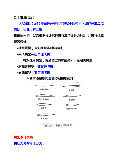
2.3翼型设计大展弦比(≥8)亚音速运输机半翼展中段较大区域存在准二维流动,因此,在二维机翼确定后,就需根据设计指标进行翼型设计/选择,并进行机翼配臵设计。
〃标准翼型,有对称和非对称两种;〃尖头翼型—超音速飞机有双弧形翼型,普通翼型前缘削尖和平板削尖翼型;〃超临界翼型—亚音速飞机;〃层流翼型—亚音速飞机自然层流翼型和层流控制翼型两种。
翼型设计发展由压力分布形态分为:尖峰翼型;●超临界翼型—长的超音速区;●全自然层流翼型—长层流流动区;●后缘分叉翼型—新概念翼型:基于后缘分离的翼型设计思想—背离库塔条件。
后缘分叉翼型设计原理●Aerobie 翼型—提供环形、飞碟、碟形翼飞行器稳定性Aerobie 翼型2.3.1 翼型种类与特征气动特征:层流、高升力、超临界;用途:飞机机翼、直升机旋翼、螺旋桨、风机翼型等。
1、早期翼型1912年:英国RAF-6/15翼型;一战:德国哥廷根翼型;1920-:美国NACA4、5和6系列层流翼型,前苏联ЦАГИ翼型;德国DVL翼型。
设计方法:半经验,依赖于风洞试验。
2、现代先进翼型1960年代开始;设计方法:计算空气动力学发展,按指定目标压力分布/优化方法设计。
种类:超临界翼型、先进高升力翼型、自然层流翼型。
2.3.2翼型的气动设计翼型的几何描述图1 翼型几何定义示意图上表面坐标:下表面坐标:前缘,后缘,弦线,弯度线(中弧线),厚度,弯度,前缘半径,后缘角。
一、经典翼型1、NACA4、5位数字翼型现在普遍使用的NACA系列翼型始于1929年,在兰利变密度风洞中的系统研究,称为4位数系列翼型。
这族翼型有相同的基本厚度分布,可以通过系统的变化弯度类型和量值得到该族相关的其他翼型。
研究得到的这族翼型比以前发展的翼型有更大的最大升力和较小的最小阻力。
研究也得到了翼型中线和厚度对翼型气动特性的影响。
具有相同厚度分布但最大弯度位臵有很大提前的翼型称为5位数系列翼型。
这族翼型显示了更好的特性,除了在失速时有突然的升力外。
25kg级固定翼无人机机翼参数
25kg级固定翼无人机机翼参数下载提示:该文档是本店铺精心编制而成的,希望大家下载后,能够帮助大家解决实际问题。
文档下载后可定制修改,请根据实际需要进行调整和使用,谢谢!本店铺为大家提供各种类型的实用资料,如教育随笔、日记赏析、句子摘抄、古诗大全、经典美文、话题作文、工作总结、词语解析、文案摘录、其他资料等等,想了解不同资料格式和写法,敬请关注!Download tips: This document is carefully compiled by this editor. I hope that after you download it, it can help you solve practical problems. The document can be customized and modified after downloading, please adjust and use it according to actual needs, thank you! In addition, this shop provides you with various types of practical materials, such as educational essays, diary appreciation, sentence excerpts, ancient poems, classic articles, topic composition, work summary, word parsing, copy excerpts, other materials and so on, want to know different data formats and writing methods, please pay attention!25kg级固定翼无人机机翼参数概述在25kg级固定翼无人机设计中,机翼参数是至关重要的考量因素。
飞行动力学专业英语词汇

飞行动力学专业英语词汇翻译飞机;飞具;航空器aircraft (ACFT)飞机失事aircraft accident飞机失事报告Aircraft Accident Report (AAR)飞机结构基准重量aircraft airframe unit weight航空器进场分类aircraft approach category飞机组装aircraft assembly飞机基本重量aircraft basic weight飞机校准参考线aircraft boresight reference line航空母舰aircraft carrier飞机分类aircraft categories飞机垂直云幕;飞机升限;飞机舱顶aircraft ceiling飞机证照aircraft certificate航空器等级aircraft classes航机分类号码aircraft classification number (ACN)飞机离场证aircraft clearance机况监视系统aircraft condition monitoring system (ACMS)飞机构型aircraft configuration飞机除冰aircraft deicing飞具设计aircraft design飞机编号aircraft designations飞机签派员aircraft dispatcher飞具阻力aircraft drag飞机带电aircraft electrification飞机空重aircraft empty weight航空发动机aircraft engineB-A电离真空计B-A gaugeB-基值B-basis巴氏合金Babbitt metal多路干扰;串音babble逆转back反方位角back azimuth后射波束back beam反方位back bearing返航感染back contamination背航道back course背航道区back course sector回流back flow风向逆转back of wind欠拨back order撤销倒数back out回压back pressure反向散射back scatter备分件;后援back up挡片back up plate后视野back view回功比back work ratio饱和余度电力back-off power回火backfire背景光度background luminance回载backhaul目视飞行天气 C weather座舱视角C-ckpit cutoff angleC-阶段C-stage舱cab顶架cabane机舱;座舱cabin座舱高度cabin altitude座舱服务员座位(可收回的)cabin attendant seat (retracted) 座舱吹气机cabin blower座舱长cabin chief空服组员cabin crew座舱失压cabin decompression座舱加温系统cabin heating system座舱灯cabin light座舱压力高度表cabin pressure altimeter座舱增压器cabin supercharger密封舱cabin; air tight客舱cabin; passenger加压舱cabin; pressurized钢绳;缆;电报cable绳夹;缆夹cable clamp钢索护罩cable guard吊绳悬空(直升机)cable hover钢缆编接cable splice钢绳张力指示器cable tension indicator达兰伯诡论D'Alembert's paradox达兰伯原理D'Alembert's principle雷管枪D-gunD形环(开伞扣环)D-ring日极值daily extremes每日检查daily inspection (DI)日平均daily mean每日会议daily meeting日较差daily range温度日较差daily range of temperature日变化daily variation每日天气图daily weather chart每日天气图daily weather map道尔顿定律Dalton's law损伤;损害;损坏damage损坏情况评估damage assessment损坏周期damage cycle损坏侦测时距damage detection period损坏侦测阈限damage detection threshold损害降低damage limitation损坏模态与效应分析damage modes and effect analysis损坏容忍度;容损damage tolerance容损设计damage tolerance design容损分级damage tolerance rating (DTR)受损飞机damaged aircraft电器电子设施舱 E & E compartmentE-玻璃纤维E-glass耳塞ear blocks耳塞ear plugs耳膜eardrum早期警报;预警early warning (EW)早期警报(预警)雷达early warning radar早期警报(预警)卫星early warning satellite地球陀螺仪earth gyroscope地球水平传感器earth horizon sensor地球轨道会合earth orbit rendezvous (EOR)地球资源环绕卫星earth resources orbiting satellite (EROS)地球资源卫星earth resources satellite (ERS)地球资源技术卫星earth resources technology satellite (ERTS) 地球卫星earth satellite地面电台earth station接地端earth terminal地球大气earth's atmosphere地磁场earth's magnetic field地转修正earth's rate correction地球反照率earth-albedo地表参考系earth-fixed reference东北东east north east (ENE)东南东east south east (ESE)东风波easterly waveFAA失事顾问FAA accident advisorFAA失事调查人员FAA accident participantsFAA飞机FAA aircraftFAA协调员FAA coordinatorFAA主任调查员FAA investigator-in-charge蒙布fabric伞布fabric; parachute制造;焊接组合fabrication防护面罩face curtain表皮face sheet表层护片face sheets面对面face to face面板faceplate国际空运便利facilitation of international air transport (FAL)便利其它项目维修(而拆装组成件)facilitation of other maintenance 设施facilities (FAC)设施及业务facilities and services设施facility设施性能分类facility performance category夹心面板facings传真facsimile传真图(气象)facsimile chart传真发送facsimile transmission (FAX)因子;因素;因子;系数factor安全因子factor of safety重力负荷G loadsG适应错觉G-adaptation illusion落地冲场g-breakG差异错觉G-differential illusionG显示器G-display超G错觉G-excess illusiong力g-forceG力诱导失去知觉g-induced lost of consciousness (GLOC)G轨域G-layer加速表g-meter抗G衣g-suit耐G力g-tolerance计;表;规gage表压力gage pressure增益gain天河坐标galactic coordinates银河宇宙射线galactic cosmic ray银纬galactic latitude银经galactic longitude银河杂波galactic noise银河辐射galactic radiation银河系Galaxy星系galaxy大风gale强风警报gale warning氢弹 H-bombH型显示器 H-displayH形发动机 H-engine水平力 H-forceH形尾翼 H-tail行为模式干扰 habit pattern interference习惯模式取代 habit pattern substitution适应;成瘾;习惯化 habituation航行时计;船表 hack watch哈根佰意索意流 Hagen-Poiseuille flow雹 hail雹阶段 hail stage冰雹 hailstone雹暴 hailstorms毛发湿度记录表 hair hygrograph毛发湿度计 hair hygrometer裂纹 hairline crack半区间法 half interval method半衰期 half life半负载 half load半分钟转弯 half minute turn半功率(点) half power (point)半滚 half roll半快滚 half snap roll半衰减厚度 half thickness冰积 ice accretion积冰指示器 ice accretion indicator冰河时期 ice age冰映光 ice blink冰冠 ice cap冰晶 ice crystal冰晶云 ice crystal cloud冰晶霾 ice crystal haze冰日 ice day探冰及防冰系统 ice detection and protection system 冰羽 ice feathers冰花 ice flowers冰雾 ice fog结冰核 ice formation-nuclei吸入冰块 ice ingestion积冰负载 ice load冰针 ice needle冰核 ice nucleus跑道积冰 ice on runway (IR)冰珠 ice pellets (PE)冰板 ice plate冰点 ice point冰极 ice pole冰雨 ice rain冰层 ice sheet起重机;千斤顶jack插头箱jack box制动螺杆jack screw起重支点jacking point千斤垫jackpad支索;撑杆jackstay锁螺帽jam nut扰讯比jam/signal ratio (J/S)干扰器饱和范围jammer saturation range (JSR)自动搜索干扰器jammer; automatic search干扰jamming干扰分析与传送挑选jamming analysis and transmission selection (JATS)干扰及警示系统jamming and warning system (JAWS)干扰火箭jamming rocket标枪队形javelin formation颚;夹片jaw叉头螺栓jaw bolt叉头板jaw plate急冲;急动jerk喷流;喷射机jet涡轮机煤油jet A喷射机飞行导引区jet advisory area喷射时代jet age喷射飞机jet airplane喷流偏向板jet blast deflector (JBD)镍铬合金K MonelK波带K-bandK图K-chartK型显示器K-displayK型装货机K-loaderK型桁架K-trussK型翼K-wing地面透气管kanat唐特维兹-唐纳生进气口Kantrowitz-Donaldson Inlet凯通(耐热塑料模);聚亚酰胺膜Kapton卡门涡列Karman street卡门-摩尔理论Karman-Moore theory卡门-钱学森理论Karman-Tsien theory下坡风katabatic wind下滑锋katafront降压区katallobar冷率温度表katathermometer考夫曼离子发动机Kaufman ion engine龙骨keel龙骨面积keel area内龙骨keelson凯氏温标Kelvin temperature scale肯尼迪太空中心(美)Kennedy Space Center (KSC)凯厄里-赫维赛游离层Kennelly-Heaviside layer刻卜勒定律Kepler's lawL-1抗G动作L-1 maneuverL波带L-bandL型显示器L-display标签;符号label防漏片;气封labyrinth seal系索lacing cord泪腺lacrimal apparatus乳酸酶缺乏症lactase deficiency乳酸lactic acid多孔(云)lacunosus激光雷达ladar梯形网络ladder network落后;迟滞lag落后角lag angle滞面阻尼lag-plane damping仪表滞差lag; instrument摇曳铰炼lagging hinge迟滞运动lagging motion洗流滞后lagging of downwash拉格朗奇坐标Lagrangian coordinate拉格朗奇点Lagrangian points伯光亮度单位lambert蓝伯特正圆锥投影法Lambert conformal conic projection 蓝伯特投影Lambert projection蓝伯特公式Lambert's formulaM-波带M-bandM型返波器M-carcinotronM型显示器M-display马赫Mach马赫角Mach angle马赫抖振Mach buffet马赫蜂鸣(副翼)Mach buzz (aileron)马赫锥Mach cone马赫效应Mach effect马赫锋;震波锋Mach front马赫数维持Mach hold震波交会点Mach intersection马赫极限Mach limit马赫线Mach line马赫表Mach meter马赫指针Mach needle火速未能接近目标Mach no马赫数Mach number震波反射Mach reflection马赫速率Mach speed马赫锋;震波锋Mach stem马赫数配平补偿器Mach trim compensator (MTC)马赫数配平耦合器Mach trim coupler马赫数配平系统Mach trim system马赫下俯Mach tuck多体问题N-body problemNACA翼形系列NACA airfoil seriesNACA低阻整流罩NACA low drag cowlNACA标准大气NACA standard atmosphere短舱(发动机)nacelle无线电环形天线盒nacelle; radio loop贝母云;真珠母云nacreous clouds天底(点)nadir天底点nadir point匐伏飞行nap of earth (NOE)汽油弹napalm嗜睡病narcolepsy麻醉剂narcotics窄频带narrow band鼻瘜肉nasal polyposis鼻咽nasopharyngeal国家科学院(美)National Academy of Science (NAS)国家航空顾问委员会(美)National Advisory Committee for Aeronautics (NACA)国家航空太空总署(美)National Aeronautics and Space Administration (NASA)国家航空协会(美)National Aeronautics Association (NAA)国家太空飞机(美国x-30)National Aerospace Plane (NASP)国家航天标准(英)National Aerospace Standard国家航空太空博物馆(美)National Air and Space Museum (NASM) 国家空域系统(美)National Airspace System (NAS)国家标准局(美)National Bureau of Standards (NBS) "超""G""" "over ""G"""目标;标的objectives扁率oblateness圆形轨道扁率oblateness in circular orbit地球扁率oblateness of the earth斜角oblique angle倾斜照相机oblique camera倾斜麦克托投影oblique Mercator斜视像片;倾斜照相oblique photograph斜震波扩散器oblique shock diffuser斜震波进气道oblique shock inlet斜震波oblique shock wave斜视程oblique visual range斜翼oblique wing (OW)斜翼单机身oblique-wing single fuselage (OWSF)斜翼变机身oblique-wing twin fuselage (OWTF)视障;天空不明obscuration观察机observation airplane观察飞行observation aviation观察气球observation balloon观测误差observation error观测站observation post观测日observational day观测曙光observational twilight天文台observatoryP波带P-bandP型显示器P-display控制靶机pace太平洋高压Pacific high太平洋飞弹试验场Pacific Missile Range (PMR)太平洋边缘区Pacific Rim太平洋标准时间Pacific Standard Time决定性的项目pacing item全套交易飞机package aircraft固定机枪package gun装箱燃料packaged propellant填料packing填圈packing ring发射架座pad整流罩垫pad; cowl统调电容padding capacitor阔叶螺旋桨paddle blade propeller板形电门paddle switch横轴旋翼机paddleplane挂锁padlock测霜仪pagoscope添条系统paint stripe system古气候paleoclimate古气候学paleoclimatology联合螺帽palnutQ值Q factorQ型天线Q-aerialQ频带Q-bandQ代码Q-codeQ角落Q-corner (coffin corner)低噪音风扇Q-fanQ系列推进剂Q-series propellants四蕊导线quad4功能雷达quadradar象限quadrant (QUAD)导航电台扇形区quadrant of a radio range象限高度quadrantal altitude象限罗差quadrantal deviation象限误差quadrantal error象限航向quadrantal heading象限点quadrantal points象限隔离quadrantal separation区信号quadrantal signal四翼飞机quadruplane四用记录器quadruple register品质;干度(热)quality质量保证quality assurance (QA)质量管理quality control (QC)量子化quantization检疫quarantine雷保;无线电探空气球 rabal相邻雷达干扰 rabbit恐水症;狂犬病 rabies环形航线 race pattern环形航线 racetrack炸弹架 rack支架控制 rack control雷达波吸收材料 radar absorbent material (RAM) 雷达咨询 radar advisory雷达天线 radar aerial雷达飞航管制中心 radar air traffic control center (RATCC)雷达高度计 radar altimeter雷达测高区 radar altimetry area雷达高度 radar altitude雷达高度警示系统 radar altitude warning system (RAWS)雷达进场 radar approach雷达进场辅助 radar approach aid (RAD)雷达进场管制 radar approach control (RAPCON)雷达到场 radar arrival雷达信标 radar beacon (racon)雷达回波识别信号 radar blip identification message (RBI)雷达轰炸 radar bombing雷达投弹瞄准具 radar bombsight雷达天线轴 radar boresight line雷达航图 radar chartS频道 S-bandS-玻璃纤维 S-glass蛇行转弯 S-turn支承环 sabot军刀机 sabrejet战略空军司令部指挥管制系统(美) SAC automated command and control system (SACCS)战略空军司令部数字信息网络(美) SAC digital information network (SACDIN)球囊(内耳膜迷路两囊中之小囊) saccule气压鞍 saddle安全间隙 safe gap安全套带 safe harness寿限内安全结构 safe life structure安全负载 safe load安全观测员 safe observer安全警戒 safety alert安全高度 safety altitude安全备炸装置 safety arming device安全网 safety barrier保险带;安全带 safety belt安全掣子 safety catch安全系数 safety factor安全油料 safety fuel安全高度 safety height安全限度 safety margin安全状态与失误隔离 safety mode and fault isolationT型尾翼T-tail调整片;片;标签tab调整片面积tab area调整片弦tab chord锁片垫圈tab washer平衡片tab; balancing操纵片tab; control伺服片tab; servo配平片tab; trim组织装备表table of organization and equipment表一table Ⅰ表列高度tabulated altitude太康距离指示器TACAN distance indicator太康台编号tacan station number转速表tachometer转速表组tachometer unit心博过速tachycardia粘性tack无粘性tack-free战术空军tactical air force太康;战术导航tactical air navigation (TACAN)战术导航判读系统tactical air navigation system (Tans)战术空军作战tactical air operation战术飞机训练系统tactical aircraft training system (TATS) 战术轰炸tactical bombing潜水艇(德) U-boat铀原子弹 U-bombU形管流体压力计 U-tube manometer雨量器 udometer溃疡 ulcer溃疡性结肠炎 ulcerative不足量 ullage加压余量燃料引擎(火箭) ullage engine加压余量燃料操纵(火箭) ullage manoeuvre终极分析 ultimate analysis终极抗压应力 ultimate compressive stress终极负载 ultimate load终极负载因素 ultimate load factor终极弹性力 ultimate resilience终极灵敏性 ultimate sensitivity终极强度 ultimate strength终极应力 ultimate stress终极抗拉应力 ultimate tensile stress超测微表 ultra micrometer超短波 ultra short wave超高旁通比 ultra-high bypass-ratio超高频 ultra-high frequency (UHF)超高频导航系统 ultra-high frequency navigation system 超真空 ultra-high vacuum超轻型飞机(小于1000磅) ultra-light aircraftV形天线V-aerialV形发动机V-engineV-g图V-g DiagramV型尾翼V-tail垂直/短场起降V/STOL疫苗vaccination真空袋成形vacuum bag molding真空计vacuum gauge真空比冲vacuum specific impulse真空式风洞vacuum tunnel迷走神经反弹vagal rebound价值工程value engineering阀;瓣;气门valve阀齿轮valve gear阀帽valve hood阀迟关valve lag阀早关valve lead阀门上升量valve lift进排气门同开valve overlap瓣式伞valve parachute阀衬valve petticoat阀门系统调整valve rigging阀门定时valve timing排气阀valve; relief心脏瓣膜疾病valvular heart diseaseW形发动机 W-engineW形机翼 W-wing尖叫音调 wailing tone机身中段 waist机身缩腰 waisting; fuselage缺点免计;豁免 waiver尾流 wake尾流分析 wake analysis尾流效应 wake effects尾流形状 wake shape尾流互制噪音 wake-interaction noise尾流扰动 wake-turbulence手提式氧气瓶 walk-around bottle起落架摆振 walking; gear边壁限制(风洞) wall constraint战争消耗品 war consumer战争模拟;兵棋 war game战备物资 war reserve作战紧急马力 war-emergency power备战备用组件 war-readiness spare kit库房 warehouse弹头 warhead弹头增益 warhead gain弹头威力 warhead yield爆震集束弹头 warhead-blast cluster发射时刻(火箭)XX型发动机X engine不适飞行天气X weatherX翼机X wingX加时间X+timeX轴晶体X-cut crystal实验型飞机X-planeX减时间X-time氙(气体名)Xenon发射机关断灯xmtr off light发射机调谐灯xmtr tune light染料xylidineY轴晶体Y-cut crystal八木天线Yagi antenna码yard (YD)线股;纱yarn偏航;偏流yaw偏航角yaw angle偏航轴;垂直轴yaw axis偏航控制yaw control偏航控制增益系统yaw control augmentation system抗偏器yaw damper偏航失稳yaw unstability侧滑片yaw vane偏航力矩yawing moment偏航力矩系数yawing moment coefficient滚转偏航力矩系数yawing moment-due-to roll侧滑偏航力矩系数yawing moment-due-to sideslip偏航表yawmeter天文年(365天5时48分53.16秒)year; astronomical 闰年year; bissextile宇宙年(太阳银河系自转一周的时间)year; cosmic国际地球物理年Year; International Geophysical (IGY) 国际太空年Year; International Space (ISY)闰年year; leap光年(光一年所走的距离)year; light太阳年(365天5时48分45.68秒)year; solarZ修正量 Z correctionZ信标 Z-beaconZ形搜索飞行 Z-search早期后缘翼的一种 Zapp flap格林威治标准时间 Zebra timeZZ进场系统 Zed-Zed天顶 zenith天顶距 zenith distance天顶天底轴 zenith nadir axis天顶雨 zenithal rains和风;夏季暖风 zephyr齐柏林(飞船) Zeppelin零;零点;零位;零度 zero零方位 zero azimuth零高云幕 zero ceiling无缺点 zero defect零频率鉴别器 zero frequency discriminator无油重量(最大起飞重量减去燃料重) zero fuel weight (ZFW) 无重状态 zero gravity开始时间 zero hour零长发射器(无导管) zero launcher零长 zero length零长发射 zero length launching (Zell)零升力角 zero lift angle零升力攻角 zero lift angle of attack。
流体力学中英文术语

流体力学中英文术语Index 翻译(Fluid Mechanics)Absolute pressure,绝对压力(压强)Absolute temperature scales, 绝对温标Absolute viscosity, 绝对粘度Acceleration加速度centripetal, 向心的convective, 对流的Coriolis, 科氏的field of a fluid, 流场force and,作用力与……local, 局部的Uniform linear, 均一线性的Acceleration field加速度场Ackeret theory, 阿克莱特定理Active flow control, 主动流动控制Actuator disk, 促动盘Added mass, 附加质量Adiabatic flow绝热流with friction,考虑摩擦的isentropic,等熵的air, 气体with area changes, 伴有空间转换Bemoullii’s equation and, 伯努利方程Mach number relations,马赫数关系式,pressure and density relations, 压力-速度关系式sonic point,critical values, 音速点,临界值,stagnation enthalpy, 滞止焓Adiabatic processes, 绝热过程Adiabatic relations, 绝热关系Adverse pressure gradient, 逆压力梯度Aerodynamic forces, on road vehicles, 交通工具,空气动力Aerodynamics, 空气动力学Aeronautics, new trends in, 航空学,新趋势Air空气testing/modeling in, 对……实验/建模useful numbers for, 关于……的有用数字Airbus Industrie, 空中客车产业Aircraft航行器airfoils机翼new designs, 新型设计Airfoils, 翼型aspect ratio (AR), 展弦比cambered, 弧形的drag coefficient of , 阻力系数early, 早期的Kline-Fogleman, 克莱恩-佛莱曼lift coefficient, 升力系数NACA,(美国) 国家航空咨询委员会separation bubble, 分离泡stalls and, 失速stall speed, 失速速度starting vortex, 起动涡stopping vortex, 终止涡Airfoil theory, 翼型理论flat-plate vortex sheet theory, 平板面涡理论Kutta condition, 库塔条件Kutta-Joukowski theorem, 库塔-儒科夫斯基定理1thick cambered airfoils, 厚弧面翼型thin-airfoils, 薄翼型wings of finite span, 有限展宽的翼型A-380 jumbo jet, 大型喷气式客机Alternate states, 交替状态American multiblade farm HA WT, 美式农庄多叶水平轴风机Angle of attack, 攻角Angle valve, 角阀Angular momentum角动量differential equation of , 关于…的微分方程relation/theorem, 联系/理论Annular strips, 环形带Applied forces, linear momentum, 外加力,线性冲力Apron,of a dam, 大坝的护坦Arbitrarily moving/deformable control volume, 任意运动/可变形控制体Arbitrary fixed control volume, 任意固定控制体Arbitrary viscous motion, 随机粘性运动Archimedes, 阿基米德Area changes, isentropic flow. 域变换,等熵流Aspect ratio (AR), 展弦比Automobiles, aerodynamic forces on, 汽车,气动力A verage velocity, 平均速度Axial-flow pumps. 轴流泵Axisymmetric flow, stream function 轴对称流,流函数Axisymmetric Potential flow, 轴对称有势流hydrodynamic mass, 水力学质量Point doublet, 点偶极子point source or sink, 点源与点汇spherical Polar coordinates and, 球极坐标uniform stream in the x direction, x方向的均匀流uniform stream plus a point doublet, 均匀流附加点偶极子uniform stream plus a point source, 均匀流附加点源BBackward-curved impeller blades, 后向曲叶轮片,Backwater curves, 回水曲线Basic equations, non dimensional, 基本方程,无量纲的Bernoulli obstruction theory, 伯努利障碍理论Bernoulli's equation, 伯努利方程with adiabatic and isentropic steady flow, as绝热、等熵稳态流frictionless flow, 无摩擦流assumptions/restrictions for, 假想/约束HGLs and EGLs, 水力坡度线和能量梯度线steady flow energy and, 定常流动能量in rotating coordinates. 在旋转坐标下,Best efficiency point (BEP), pumps, 最佳效率点,Betz number, 贝兹数Bingham plastic idealization, 宾汉塑性理想化,Biological drag reduction, 生物学阻力衰减Blade angle effects, on pump head, 叶片安装角效率,泵头处Blasius equation, 布拉修斯方程Body drag, at high Mach numbers, 机体阻力,在高马赫数下Body forces, 体力Boeing Corp., 波音公司Boundaries, of systems, 边界,系统Boundary conditions. 边界条件,differential relations for fluid flow, 流体的微分关系nondimensionalizalion and, 无量纲化Boundary element method (BEM), 边界元方法2Boundary layer (BL) analysis, 边界层分析boundary layer flows, 边界层流动boundary layer separation on a half body, 边界层半体分离displacement thickness, 位移厚度drag force and, 阻力equations, 方程flat-plate. 平板,Karman's analysis, 卡门分析momentum integral estimates, 动量积分估计momentum integral relation. 动量积分关系momentum integral theory, 动量积分理论pressure gradient 压力梯度separation on a half body, 半模分离skin friction coefficient, 表面摩擦系数two-dimensional flow derivation, 二维流推导Boundary layers with Pressure gradient, 边界层压力梯度adverse gradient, 反梯度favorable gradient, 正梯度laminar integral theory, 层流积分理论,nozzle-diffuser example,喷口扩散算例Bourdon tube, 波登管Bow shock wave, 弓形激波Brake horsepower,制动马力Broad-crested weirs, 宽顶堰Buckingham Pi Theorem, 白金汉定理Bulb Protrusion, 球形突出物(船头)Bulk modulus. 体积模量Buoyancy, 浮力Buoyant particles, local velocity and, 悬浮颗粒,局部速度Buoyant rising light spheres, 浮力作用下自由上升的球体Butterfly valve, 蝶形阀CCambered airfoils, 弓型翼Cauchy-Riemann equations, 柯西-黎曼方程Cavitation/Cavitation number, 气穴/气蚀数Celsius temperature scales, 摄氏温标Center of buoyancy, 浮心Center of Pressure (CP),压力中心,压强中心Centrifugal pumps, 离心泵backward-curved impeller blades, 后曲叶轮片blade angle effects on pump head, 泵头处叶片安装角效率brake horsepower, 制动马力circulation losses, 环量损失closed blades, 闭叶片efficiency of, 效率的elementary pump theory. 基泵理论Euler turbomachine equations, 欧拉涡轮机方程eye of the casing, 泵体通风口friction losses, 摩擦损失hydraulic efficiency, 水力[液压]效率mechanical efficiency.机械效率open blades, 开放式叶片output parameters, 输出参数power, delivered, 功率,传递pump surge, 泵涌,scroll section of casing, 卷形截面,泵体,shock losses, 激波损失vaneless, 无叶片的3volumetric efficiency, 容积效率[系数]water horsepower, 水马力Centripetal acceleration, 向心加速度Channel control Point, 传送控制点Characteristic area. external flows, 特征区域,外流Chezy coefficient, 薛齐系数Chezy formula, 薛齐公式Chezy coefficient,薛齐系数flow in a Partly full circular pipe, 流体非充满的圆管流Manning roughness correlation. 曼宁粗糙度关系,normal depth estimates, 法向深度估计Choking, 壅塞;堵塞of compressors, 压缩机的due to friction, compressible duct and, 由于摩擦,可压缩管的isentropic flow with area changes, 变横截面积等熵流simple heating and, 单纯加热Circular cylinder, flow with circulation. 圆柱体,Circulation环量and flow past circular cylinder, 流体经过圆柱体losses, in centrifugal pumps, 损失,离心泵potential flow and, 有势流Circumferential pumps, 环型泵Classical venturi, 标准文氏管Closed blades, centrifugal pumps. 闭叶片,离心泵Closed-body shapes, 闭体外形,circular cylinder, with circulation, 圆柱体,环量Kelvin oval, 开尔文椭圆,Kutta-Joukowski lift theorem,库塔-儒科夫斯基升力定理,Potential flow analogs, 有势流模拟Rankine oval, 兰金椭圆rotating cylinders. lift and drag, 旋转柱体,升力与阻力Coanda effect, 柯恩达效应( 沿物体表面的高速气流在Cobra P-530 supersonic interceptor, 眼镜蛇超音速拦截机Coefficient matrix. 系数矩阵Coefficient of surface tension, 表面张力系数Coefficient of viscosity, 粘滞系数Commercial CFD codes, viscous flow, 商业的计算流体力学代码,粘流Commercial ducts, roughness values for, 商业管道Composite-flow, open channels, 合成流,开槽道Compressibility, non dimensional. 压缩性,无量纲Compressibility effects, 压缩效果Compressible duct flow with friction, 伴有摩擦的可压缩管流adiabatic, 绝热的, 隔热的choking and, 壅塞;堵塞isothermal flow in long pipelines, 管线中的等温流动,long pipelines, isothermal flow in, 管线,等温流动,mass flow for a given pressure drop, 给定压降下质量流动minor losses in, 最小损失subsonic inlet, choking due to friction, 亚音速进口,摩擦引发阻塞,supersonic inlet, choking due to friction, 超音速进口,摩擦引发阻塞,Compressible flow, 可压缩流flow with friction摩擦流choking and, 壅塞;堵塞converging-diverging nozzles, 拉瓦尔喷管converging nozzles, 收缩喷嘴Fanno flow, 法诺流动,gas flow correction factor, 气流校正参数hypersonic flow, 高超音速气流4incompressible flow, 不可压缩流isentropic.等熵的isentropic Process, 等熵过程,Mach number, 马赫数normal shock wave. 正激波the perfect gas, 理想气体Prandtl-Meyer waves. 普朗特-麦耶膨胀波shock waves. 激波specific-heat ratio, 比热比speed of sound and,声速subsonic, 亚音速的supersonic,超音速的transonic, 跨音速的two-dimensional supersonic, 二维超音速的Compressible gas flow correction factor, 可压缩气流校正因数Compressors, 压缩机Computational fluid dynamics (CFD), 计算流体力学pump simulations, 泵模拟viscous flow. 粘流Concentric annulus, viscous flows in, 同心环Cone flows, 锥体绕流Conformal mapping, 保角映射[变换] Conservation of energy, 能量守恒定律Conservation of mass. 质量守恒定律Consistent units, 相容单元Constants, 常量dimensional, 空间的pure, 纯粹的Constant velocity, fluid flow at, 常速度, 等速度Constructs, 结构Contact angle, 交会角Continuity, 连续性,equation of ,方程nondimensionalization and, 无量纲的Continuum, fluid as, 连续流体Contraction flow, 收缩流动Control Point, channel, 控制点,管道Control volume analysis,控制体分析angular momentum theorem. 角动量定理,arbitrarily moving/deformable CV,任意运动/可变形控制体arbitrarily fixed control volume, 任意固定控制体conservation of mass, 质量守恒定律control volume moving at constant velocity, 控制体以等速运动control volume of constant shape but variable velocity作变速运动的刚性控制体energy equation. 能量方程introductory definitions, 介绍性定义linear momentum equation. 线性动量方程,one-dimensional fixed control volume, 一维固定控制体,one-dimensional flux term approximations, 一维通量项近似Physical laws. 物理定律。
风力机翼型气动特性数值计算及影响因素研究
风力机翼型气动特性数值计算及影响因素研究周茜茜;孙贺;刘晓光;王洋【摘要】二维翼型气动特性决定整个转子叶片的气动特性,分析二维翼型气动特性十分必要.文章介绍了翼型绕流及其升阻效应,并且对经典翼型NACA4415进行气动特性数值模拟计算,对翼型气动特性影响因素雷诺数、相对厚度、相对弯度等进行了研究.对翼型气动特性数值计算及其影响因素的研究,为三维叶片设计提供可靠参考,并对进一步叶片优化设计具有重要意义.【期刊名称】《可再生能源》【年(卷),期】2014(032)008【总页数】6页(P1144-1149)【关键词】翼型扰流;升阻效应;数值模拟;影响因素【作者】周茜茜;孙贺;刘晓光;王洋【作者单位】吉林大学机械科学与工程学院,吉林长春130022;吉林省计算中心(吉林省计算机技术研究所),吉林长春130022;吉林省计算中心(吉林省计算机技术研究所),吉林长春130022;吉林省计算中心(吉林省计算机技术研究所),吉林长春130022;吉林省计算中心(吉林省计算机技术研究所),吉林长春130022【正文语种】中文【中图分类】TK830 引言风轮是风力机最核心的部件,也是风力发电机中最基础和最关键的部件,其良好的设计、可靠的质量和优越的性能是保证机组正常稳定运行的决定性因素[1]~[3]。
掌握了叶片设计技术就是掌握了风力机设计技术的关键。
叶片气动性能的好坏,取决于叶片几何外形设计,包括高效的接受风能的翼型、合理的安装角、科学的升阻比、尖速比和叶片扭曲,是衡量叶片设计成功与否的标准[4]~[6]。
因此,气动性能的好坏对风轮是至关重要的。
1 翼型气动特性理论分析对于风力机而言,翼型绕流的实质为空气动力学中气体外部绕流问题[7],如图1所示。
图中u∞表示水平方向上的自由来流速度,由于翼型的存在,使得流线在前缘附近开始发生弯曲,弯曲的流线分别经翼型上下表面至尾缘重新汇合。
翼型的存在阻碍了气流前进,或者从相对运动的观点说,气流静止而翼型以u∞速度向左运动,则气流的存在阻碍了翼型前进,该效应称为阻力效应;同时,在翼型绕流过程中,气流会对翼型产生垂直于自由来流方向上的提升作用,该效应称为升力效应。
波浪滑翔机水下牵引机结构设计与分析
㊀㊀文章编号:1005 ̄9865(2020)02 ̄0092 ̄09波浪滑翔机水下牵引机结构设计与分析曹守启ꎬ冯江伟(上海海洋大学工程学院ꎬ上海㊀201306)摘㊀要:为满足对远洋环境进行长时间㊁大范围监测的实际需求ꎬ设计提出一种波浪动力滑翔机ꎬ该设备是一种无需携带能源即可实现自主航行的新型海洋监测平台ꎬ其主体结构由水面母船㊁水下牵引机和柔性缆绳三大部分组成ꎮ平台通过即时获取海洋中的波浪能㊁太阳能㊁风能作为行走的动力源ꎬ克服了传统海洋监测设备在能源供应上存在的短板ꎮ为进一步提升水下牵引机对波浪能的利用率ꎬ采用Ansys软件中的Fluent模块对水下牵引机进行水动力仿真研究ꎬ分析了侧翼板形状㊁侧翼板工作最大摆动角度以及侧翼板安装分布间距对滑翔机总体行走效率的影响ꎮ结果表明:NACA翼型侧翼板具有更好的水动力性能ꎻ随着最大摆动角度的增加ꎬ水下牵引机的推进效率先增大后减小ꎬ最大摆角在20ʎ左右时ꎬ推进效果最佳ꎻ随着侧翼板分布间距的增大ꎬ水下牵引机的推进效率逐渐减小ꎬ分布间距在80mm左右时ꎬ推进效果最佳ꎮ关键词:波浪滑翔机ꎻ结构组成ꎻ结构设计ꎻ水动力分析ꎻ性能优化中图分类号:P751ꎻU662.2㊀㊀㊀文献标志码:A㊀㊀㊀DOI:10.16483/j.issn.1005 ̄9865.2020.02.011收稿日期:2019 ̄05 ̄10基金项目:上海市科委2017年度 创新行动计划 地方院校能力建设项目 海洋环境监测用电浮标系统关键技术研究及应用示范 资助(17050502000)作者简介:曹守启(1973 ̄)ꎬ男ꎬ山东临沂人ꎬ博士ꎬ教授ꎬ博士生导师ꎬ主要从事海洋物联网工程㊁渔业工程及其自动化等技术研究ꎮE ̄mail:sqcao@shou.edu.cn通信作者:冯江伟ꎮE ̄mail:807623027@qq.comStructuraldesignandanalysisofunderwatertractorforwavegliderCAOShouqiꎬFENGJiangwei(CollegeofEngineeringꎬShanghaiOceanUniversityꎬShanghai201306ꎬChina)Abstract:Inordertomeetthepracticalrequirementsoflong ̄termandlarge ̄scalemonitoringoftheoceanenvironmentꎬawavepoweredglideranewtypeofoceanmonitoringplatformisdesignedꎬtorealizeautonomousnavigationwithoutcarryingenergy.Itsmainstructureconsistsofthreeparts:surfacemothershipꎬunderwatertractorandflexiblecable.Theplatformovercomestheshortcomingofthetraditionaloceanmonitoringequipmentinenergysupplybyacquiringtheoceanwaveenergyꎬsolarenergyandwindenergyasthepowersourcesforwalking.InordertofurtherimprovetheutilizationrateofwaveenergyoftheunderwatertractorꎬfluentmoduleinAnsyssoftwareisusedtoconducthydrodynamicsimulationresearchontheunderwatertractorꎬandtheinfluenceoftheshapeofthewingplateꎬthemaximumswingangleofthewingplateandthemaximumdistributiondistanceofthewingplateinstallationontheoverallwalkingefficiencyofthegliderisanalyzed.TheresultsshowthatNACAairfoilhasbetterhydrodynamicperformanceꎻwiththeincreaseofmaximumswingangleꎬthepropulsiveefficiencyincreasesafterthefirstunderwatertractorisreducedꎬandtopromotemaximumpendulumangleeffectatabout20ʎisthebestꎻthepropulsiveefficiencyoftheunderwatertractordecreaseswiththeincreaseofthespacingofthewingsꎬandthebestpropulsiveeffectisachievedwhenthespacingisabout80mm.Keywords:wavegliderꎻstructuralcomponentsꎻstructuredesignꎻhydrodynamicanalysisꎻperformanceoptimization近年来ꎬ随着世界各国对海洋工程装备不断深入的研究ꎬ波浪滑翔机应运而生ꎮ作为一种新型海洋工程第38卷第2期2020年3月海洋工程THEOCEANENGINEERINGVol.38No.2Mar.2020装备ꎬ它克服了传统海洋作业平台需要自带能源的弊端ꎬ无需额外提供动力源ꎬ仅靠捕获波浪能㊁太阳能及风能等新能源即可实现行走[1]ꎬ具有较高的续航能力和较强的环境适应性ꎬ可用于不同海况的海域进行长时间㊁大范围的监测任务ꎮ目前ꎬ关于波浪滑翔机的研究ꎬ我国涌现出不少专家学者ꎬ并取得了初步成果ꎮ李小涛等人将波浪滑翔机与其它监测设备进行了对比[2]ꎬ研究发现波浪滑翔机具有长时间㊁大范围监测的优势ꎮ田宝强等人研究了波浪滑翔机的运动效率[3]ꎬ论述了水下牵引机的推进原理ꎬ分析和计算了波浪的波高和周期对平台运动效率的影响ꎬ为后续水下牵引机结构的优化分析提供了理论基础ꎮ贾力娟研究了波浪滑翔机的工作机理以及运动情况[4]ꎬ建立起波浪滑翔机的二维动力学模型ꎬ将模型导入软件进行运动仿真研究ꎮ总的来说ꎬ我国针对波浪滑翔机的研究仍处于起步阶段ꎬ关于该设备的结构设计和三维水动力学分析的相关文献较少ꎮ文中考虑水下牵引机主体结构参数对水动力性能的影响ꎬ率先通过ANSYS软件进行三维数值模拟ꎬ并采用控制变量法对水下牵引机翼型选择㊁侧翼板的最大摆动角度及安装分布间距进行水动力仿真研究ꎬ将水下牵引机的设计参数作进一步的优化ꎬ为同类型波浪滑翔机水下牵引机的设计提供了更加可靠的参考建议ꎮ1㊀波浪动力滑翔机1.1㊀总体结构波浪滑翔机主要由漂浮在水面上的水面母船和浸没在水中的水下牵引机以及位于二者之间用于连接水面母船和水下牵引机的柔性立管缆绳三大部分组成ꎮ水面母船主要用于安装太阳能电池板㊁风力发电装置㊁电控系统以及监测系统中用到的各类传感器㊁水下摄像头和声纳等设备[5]ꎻ水下牵引机由垂直安装的主支撑框架和平行安装的侧翼板组成ꎬ是整个平台行走的主要动力来源ꎻ柔性立管缆绳用于连接水面母船和水下牵引机ꎬ并在其内部安装用于水面母船和水下牵引机通信的电缆ꎮ图1为波浪滑翔机的三维模型:水面母船长2~3mꎬ宽0.6~0.8mꎻ水下牵引机长2~2.6mꎬ高0.3~0.6mꎬ侧翼板宽1~1.5mꎻ柔性缆绳长6~7mꎮ1.2㊀工作原理波浪滑翔机主要依靠捕获波浪能作为动力源进行推进ꎬ同时水面母船上装有太阳能电池板和风力发电装置作为辅助动力源ꎬ并通过转向尾舵进行方向的掌控ꎮ太阳能电池板和风力发电装置捕获的电能储存在蓄电池中ꎬ用于整个平台电力系统的能源供应ꎮ在滑翔机随波浪爬升的过程中ꎬ柔性缆绳处于紧绷状态ꎬ水面母船拖动水下牵引机上移ꎬ此时水下牵引机的侧翼板在水动力的作用下向后下方转动ꎬ从而产生使水下牵引机向前运动的推力ꎻ在滑翔机随波浪回落的过程中ꎬ柔性缆绳处于松弛的状态ꎬ水下牵引机靠其自身的重力下移ꎬ此时水下牵引机的侧翼板在水动力的作用下向后上方转动ꎬ从而也产生使水下牵引机向前运动的推力ꎬ因此ꎬ不论水下牵引机上升还是下移ꎬ其侧翼板受到的水平分力总是向前[6]ꎮ如此反复ꎬ就将滑翔机随波浪的上下起伏运动转化为水下牵引机向前的运动ꎬ从而实现了整个波浪滑翔机的持续向前运动ꎮ其受力情况如图2所示ꎮ图1㊀波浪滑翔机三维模型结构示意Fig.1㊀Schematicdiagramof3Dmodelstructureofwaveglider图2㊀水下牵引机受力分析Fig.2㊀Forceanalysisofunderwatertractor39第2期曹守启ꎬ等:波浪滑翔机水下牵引机结构设计与分析2㊀水下牵引机的结构设计水下牵引机主要由主体支架㊁六组互相平行安装的侧翼板㊁转向尾舵和万向节吊钩等组成ꎬ其中ꎬ主体支架的结构形状㊁侧翼板结构的重心和浮心位置会直接影响到整个波浪滑翔机波动推进的效率ꎮ因此ꎬ水下牵引机在设计过程中需要着重考虑以下几个关键图3㊀水下牵引机三维模型Fig.3㊀3Dmodelofunderwatertractor点[7]:①为了保证水下牵引机在升降运动过程中姿态的稳定性ꎬ吊点㊁浮心㊁重心和水动力中心必须位于同一条竖直线内ꎻ②水下牵引机侧翼板的翼型和尺寸需要与实际海况的水流冲刷作用相适应ꎬ保证较高的前行效率与适当的垂向往复运动频率ꎻ③侧翼板的分布间距和摆动角度应与实际海况相适应ꎬ以保证较高的推进效率ꎮ综合目前波浪滑翔机水下牵引机的外形特征ꎬ利用Solidworks三维制图软件对水下牵引机进行建模ꎬ建模结果如3所示ꎬ主要技术参数如表1所示ꎮ表1㊀水下牵引机设计关键参数Tab.1㊀Keyparametersofunderwatertractordesign技术参数数值技术参数数值水下牵引机总长/m2.2水下牵引机总高/m0.5侧翼板宽度/m1.46翼展攻角/(ʎ)20翼展弦长/mm160最大厚度/mm10.23㊀水下牵引机水动力仿真研究3.1㊀理论基础3.1.1㊀基本控制方程在流体仿真计算中ꎬ不管是模拟水下牵引机的定常运动ꎬ还是模拟水下牵引机的非定常运动ꎬ都需要选取恰当的湍流模型ꎮ对水下牵引机进行仿真计算时ꎬ水流流过其流场ꎬ通常状况下将流体看作是不可压缩的液体ꎬ并假设在整个计算过程中没有任何热能交换的发生ꎬ此时则可以采取不可压缩介质的雷诺平均纳维-斯托克斯(ReynoldSaveragedNavier ̄StokesꎬRANS)方程来作为其求解控制方程ꎬ流体在流动过程中满足基本的牛顿力学定律㊁质量守恒定律㊁动量守恒定律和能量守恒定律[8]ꎬ对于黏性的不可压缩牛顿流体建立如下连续方程:∂ui∂xi=0∂ui∂t+∂∂xi(uiuj)=-1ρ∂P∂xi+v∂∂xi(∂ui∂xi+∂uj∂xj)ìîíïïïïï(1)式中:ui(i=1ꎬ2ꎬ3)分别为三个坐标轴方向上的速度分量ꎬxi(x=1ꎬ2ꎬ3)分别为三个坐标轴方向上的坐标分量ꎬP为压力ꎬρ为流体的密度ꎬv为流体的运动黏性系数ꎬt为时间ꎮ在模拟湍流运动计算时ꎬ方程中的变量是由分解平均量和脉动量构成:φ=φ+φ'(2)再对方程左右两侧的时间取平均ꎬ得到不可压缩流体RANS方程的张量形式:∂ui∂xi=0ρ∂u∂t+ρ∂∂xj(uiuj)=-∂P∂xj+∂P∂xj[μ(∂ui∂xj+∂uj∂xj-23δij∂ui∂xj)]+∂u∂xj(-ρu'iu'j)ìîíïïïïï(3)49海㊀㊀洋㊀㊀工㊀㊀程第38卷式中:uiꎬujꎬP为速度和压力的时均量ꎻ-ρu'iu'j为雷诺应力项ꎬ亦称作雷诺应力张量ꎬ它有六个不同的量组成ꎮ-ρu'iu'j=μt(∂ui∂xi+∂uj∂xi)-23(ρk+μt∂ui∂xi)δy(4)式中:k为湍流动能ꎬμt为湍流黏度ꎮBoussinesq常常用于湍流模型ꎬ其优点是在计算湍流黏度时所耗费的时间较少ꎮ在k ̄ε中使用时ꎬ必须多解一对方程ꎬ分别是与湍流耗散率和湍流动能有关的方程ꎬ求解时将μt看成k和ε的函数ꎮBoussinesq黏度有一个很大的缺点:它认为μt是一个标量ꎬ在某些情况下使用可能会出现较大的误差ꎮ3.1.2㊀湍流模型一般地ꎬ模拟湍流时有三种常见的方法:大涡模拟法(LES)㊁直接数值模拟法(DNS)和平均N ̄S方程求解法ꎮ在模拟湍流方法的计算中ꎬ通常采用平均N ̄S方程的方法进行求解[9]ꎬ平均N ̄S方程求解法用来求解数值模拟中相对较为复杂的一些问题ꎬ其本质是对N ̄S方程中的时间概念进行平均计算ꎬ然后得到所建立的湍流时间平均运动方程ꎬ即RANS方程ꎮ由于平均N ̄S方程的不封闭性通常含有新的未知数变量 雷诺应力ꎬ故湍流模型常用来求解封闭方程组问题ꎮk ̄ε湍流模型在计算水下牵引机的流体力学计算中用作广泛ꎮk ̄ε湍流模型的计算类型共有三种ꎬ分别为Standard㊁RNG和Realizableꎮ通常情况下ꎬRNG计算类型用来求解有涡流存在的一系列较为复杂的问题ꎮ本文所设计的水下牵引机体型较小ꎬ雷诺数较低ꎬ选用RNG计算水动力学参数ꎬ计算结果相对准确ꎬ也符合实际问题中的理论值ꎮRNG计算如下:ρ∂∂t(k)+ρ∂∂xi(kui)=∂∂xj(αεuεjj∂k∂xi)+Gk-ρk+Sk(5)ρ∂∂t(ε)+ρ∂∂xi(εui)=∂∂xj(αεuεjj∂k∂xi)+C1εεkGk-C2εε2k-Rε+Sε(6)式中:uεjj为有效黏度ꎬSk与Sε为源项ꎬGk为湍流动能ꎬ计算如下:Gk=-ρu'iu'j∂uj∂ui(7)RNG计算中ꎬ湍流黏度方程为:d(ρ2kεμ)=1.72v-v-2-1+Cvdv-(8)当雷诺数变高时ꎬ方程变形如下:μt=ρCμk2ε(9)式中:Cμ和Cv为经验系数ꎮ3.2㊀仿真分析3.2.1㊀计算域设置和网格划分水下牵引机的三维模型建立好后ꎬ需要根据模型的尺寸设置计算域进而进行网格的划分ꎬ设置计算域时一定要保证二者在尺寸上的适应性ꎮ采用长方体的计算域ꎬ在平行于水流流向的方向ꎬ取6倍于水下牵引机的高度为尺寸ꎬ在垂直于水流流向的方向ꎬ分别取3倍于水下牵引机的长度和宽度为尺寸建立计算域ꎬ这样可以基本保证计算的合理性ꎮ网格的划分不仅直接影响计算结果的精度ꎬ而且对计算时间的长短也影响较大ꎬ因此在划分网格时要进行综合考虑ꎬ在满足计算精度的前提下ꎬ尽量将计算时间控制到最短ꎮ在进行网格划分时ꎬ整体采用非结构网格划分ꎬ并进行局部加密处理[10]ꎬ最终的网格单元总数约为2066558ꎬ其中全局网格大小为3mmꎬ面网格大小为20mmꎬpart网格大小为5mmꎬfluid网格大小为10mmꎬ符合计算的基本要求ꎮ网格划分结果如图4所示ꎮ59第2期曹守启ꎬ等:波浪滑翔机水下牵引机结构设计与分析图4㊀计算域和水下牵引机网格划分结果Fig.4㊀Meshingresultsofcalculationdomainandunderwatertractor3.2.2㊀边界条件设定水下牵引机在竖直方向的运动状态为随波浪的起伏运动ꎬ文中所有模型的水动力分析均选取柔性缆绳拉动水下牵引机向上运动的过程ꎬ水流方向相对于水下牵引机的方向为竖直向下ꎮ将长方体流域的上边界设置为速度入口(velocity ̄inlet)ꎬ下边界设置为压力出口(pressure ̄outlet)ꎬ四周边界设置为远边界(wall)ꎮ根据实际对海洋状况的研究ꎬ并结合海况等级表取平均海况为3级海况ꎬ则海面以下6~7m处海水的垂直流速为0.75m/s左右ꎬ因此仿真计算时取入口处的速度为0.75m/sꎬ迭代计算的步数设为1000ꎬ以保证模型计算的收敛性ꎮ此外ꎬ取海洋环境条件为:海水温度4ʎCꎬ海水密度1027.77kg/m3ꎬ海水运动黏性系数1.61´10-6m2/sꎮ3.2.3㊀计算模型波浪滑翔机的主要动力来源于水下牵引机水翼的摆动ꎬ六组平行翼板翼型的选择㊁翼板的最大摆动角度以及翼板的安装间距均对波浪滑翔机的行走效率有着较大影响ꎮ因此ꎬ经过将模型简化ꎬ建立了如下三组对比计算模型:1)在其它因素均相同的条件下分别取NACA0012翼型和平板翼型进行对比仿真ꎻ2)在其它因素均相同的条件下分别取水翼的最大摆动角度θ为:5ʎ㊁10ʎ㊁15ʎ㊁20ʎ㊁25ʎ㊁30ʎ进行对比仿真ꎻ3)在其它因素均相同的条件下分别取水翼的安装间距d为:40㊁80㊁120㊁160㊁200和240mm进行对比仿真ꎮ3.3㊀仿真结果及分析3.3.1㊀翼型的选择图5㊁图6㊁图7为相同参数设置下NACA翼型和平板翼型的压力云图㊁流场流线图以及速度矢量图ꎮ图5㊀NACA翼型和平板翼型压力云Fig.5㊀PressureclouddiagramofNACAairfoilandflatairfoil图6㊀NACA翼型和平板翼型流场流线Fig.6㊀FlowfieldcurvesofNACAairfoilandplateairfoil69海㊀㊀洋㊀㊀工㊀㊀程第38卷图7㊀NACA翼型和平板翼型速度矢量Fig.7㊀VelocityvectorofNACAairfoilandflatairfoil由分析结果可知ꎬ在相同参数的情况下ꎬNACA翼型的升阻比更大ꎬ即在同等海况的条件下ꎬNACA翼型可获得更大的前向推力ꎮ此外ꎬ平板翼型的侧翼板所受压力区域较为集中ꎬ在承受较大的压力时ꎬ容易引起侧翼板的屈曲ꎬ以至于影响水下牵引机的整体推进效率ꎬ甚至可能引发水下牵引机的失效ꎻ而NACA形水翼所受的压力区域则较为分散ꎬ同时还有结构强度高ꎬ阻力系数小ꎬ水动力性能好等优点ꎮ尽管NACA翼板的加工成本远高于平板水翼ꎬ但综合各方面因素ꎬ将水下牵引机侧翼板的形状选为NACA0012型侧翼板ꎮ3.3.2㊀最大摆角确定图8为NACA0012型侧翼板在相同来流速度㊁相同分布间距㊁相同运动波长等因素下ꎬ只控制最大摆动角度不同时所得到的压力云图ꎬ最大摆动角度θ的取值为:5ʎ㊁10ʎ㊁15ʎ㊁20ʎ㊁25ʎ㊁30ʎꎮ其中ꎬ水下牵引机在不同最大摆动角度下的仿真计算结果如表2所示ꎮ表2中各项计算流体力学(CFD)参数为通过仿真计算得到的不同最大摆动角度下水下牵引机所受的总阻力㊁前向推力㊁总阻力系数㊁推力系数以及进一步计算求出的升阻比ꎮ为了更加直观地显示总阻力和推力的变化趋势ꎬ将表2数据绘制为图9㊁图10所示的曲线图ꎮ图8㊀不同最大摆角时压力云图Fig.8㊀Pressureclouddiagramatdifferentmaximumyawangles79第2期曹守启ꎬ等:波浪滑翔机水下牵引机结构设计与分析表2㊀不同水翼最大摆角 CFD分析结果Tab.2㊀Maximumswingangleofdifferenthydrofoils CFDanalysisresults最大摆角/(ʎ)总阻力D/N推力L/N总阻力系数推力系数升阻比L/D5604.785571.93880.48880.05810.118910612.1417169.73260.49480.13720.277315643.5984210.30840.52020.16700.326820653.2969295.49450.52810.23880.452325776.7271309.17280.62780.24990.398030844.9265316.11040.68290.25550.3741图9㊀不同最大摆角受力曲线Fig.9㊀Forcecurveswithdifferentmaximumyawangles图10㊀不同最大摆角升阻比Fig.10㊀Lift ̄dragratiosatdifferentmaximumyawangles分析以上图表可知ꎬ在来流速度㊁侧翼板分布间距㊁运动波长等因素一定的条件下ꎬ每个水翼所受的推力系数随最大摆动角度的变化规律大致相同ꎬ均为先增大后减小ꎬ由此可见ꎬ侧翼板的最大摆动角度存在一个最佳的数值ꎮ随着最大摆动角度的增大ꎬ推力L和阻力D均增大ꎬ只是在最佳数值之前ꎬ推力L增加的幅度大于阻力D增加的幅度ꎻ而在最佳数值之后ꎬ阻力D增加的幅度则大于推力L增加的幅度ꎬ所以升阻比表现为先增大后减小ꎮ从仿真计算的结果来看ꎬ这一最佳数值位于θ=20ʎ附近ꎮ3.3.3㊀最佳安装间距选取图11为NACA0012翼型在最大摆动角度θ=20ʎꎬ且设置来流速度㊁运动波长等因素均相同时ꎬ侧翼板在不同水翼分布间距下所得到的压力云图ꎮ安装间距d的取值为:40㊁80㊁120㊁160㊁200和240mmꎮ其中ꎬ水下牵引机在不同安装间距下的仿真计算结果如表3所示ꎮ表3㊀不同水翼分布间距 CFD分析结果Tab.3㊀Differenthydrofoilspacing CFDanalysisresults间距d/mm总阻力D/N推力L/N总阻力系数推力系数升阻比L/D40165.397489.20920.13370.07210.539480268.2369125.08760.21680.10110.4663120368.8973162.50210.29820.13130.4405160499.3689203.38450.40360.16440.4073200638.1997245.31760.51590.19830.3844240820.9062305.01110.66350.24650.3716表3中的各项CFD参数为通过仿真计算得到的侧翼板在不同分布间距下水下牵引机所受的总阻力㊁前向推力㊁总阻力系数㊁推力系数以及进一步计算求出的升阻比ꎮ为了更加直观地显示总阻力和推力的变化趋势ꎬ将表3绘制为如图12㊁图13所示的曲线图ꎮ89海㊀㊀洋㊀㊀工㊀㊀程第38卷图11㊀不同分布间距时压力云图Fig.11Pressureclouddiagramatdifferentspacingdistributions图12㊀不同水翼分布间距受力曲线Fig.12㊀Stresscurvesofdifferenthydrofoilspacing图13㊀不同水翼分布间距升阻比Fig.13㊀Lift ̄dragratiosofdifferenthydrofoilspacing分析以上图表可知ꎬ在来流速度㊁侧翼板最大摆动角度㊁运动波长等因素一定的条件下ꎬ每个水翼所受的推力系数随分部间距的变化规律大致相同ꎬ都是随分部间距的增大而减小ꎮ由此可见ꎬ适当减小水翼分部间距对提高水下牵引机的总体推进效率是有益的ꎬ因为在不同水翼分布间距下每个水翼产生的首缘涡和尾涡的方向基本相同ꎬ但强度各异ꎬ随水翼分布间距的增大ꎬ首缘涡和尾涡的强度均有所衰减ꎮ水翼分布间距较小时ꎬ前面水翼的尾涡还未完全衰减ꎬ就与后面水翼的首缘涡融合在一起ꎬ如此传递ꎬ使得每个水翼的尾涡均有一定程度的加强ꎬ从而产生较强的前向推力ꎻ而当水翼分布间距较大时ꎬ每个水翼所产生的首缘涡和尾涡衰减程度都较大ꎬ各旋涡之间的相互影响较小ꎬ产生的前向推力也较弱ꎮ当间距过小时ꎬ虽然其侧翼板获取的推力最大ꎬ但压力负载区域过于集中ꎬ水下牵引机的稳定性较差ꎬ从而影响其总体推进效率ꎬ综合考虑ꎬ取水翼分部间距为d=80mm时总体推进效果最佳ꎮ99第2期曹守启ꎬ等:波浪滑翔机水下牵引机结构设计与分析001海㊀㊀洋㊀㊀工㊀㊀程第38卷4㊀结㊀语以波浪滑翔机为研究对象ꎬ设计了该设备关键部件之一的水下牵引机ꎬ并运用Ansys软件中的Fluent模块对其进行仿真优化ꎬ同时用控制变量法对其结构的多个参数进行对比仿真研究ꎮ得到如下结论:1)NACA翼型的综合推进效率比平板翼型好ꎬ所设计的水下牵引机宜选用NACA0012翼型的侧翼板ꎮ2)在来流速度㊁分布间距㊁运动波长等因素一定的条件下ꎬ水下牵引机的总体推进效率随侧翼板最大摆动角度的增加而增大ꎬ当该角度的增大超过某一特定值时ꎬ水下牵引机的总体推进效率反而开始下降ꎬ而这一特定值位于θ=20ʎ附近ꎮ3)在来流速度㊁侧翼板最大摆动角度㊁运动波长等因素一定的条件下ꎬ水下牵引机的总体推进效率随侧翼板分布间距的增大而减小ꎬ但间距过小时ꎬ压力负载区域过于集中ꎬ容易引起水下牵引机的侧翻ꎬ从而降低其总体推进效率ꎬ综合考虑ꎬ取水翼分部间距为d=80mm时推进效果最佳ꎮ参考文献:[1]㊀张成翊ꎬ徐雪松.波浪滑翔机母船与牵引机运动传递关系[J].上海交通大学学报ꎬ2018ꎬ52(2):127 ̄132.(ZHANGChengxiangꎬXUXuesong.Therelationshipbetweenthemothershipofawavegliderandthemotiontransferofthetractor[J].JournalofShanghaiJiaoTongUniversityꎬ2018ꎬ52(2):127 ̄132.(inChinese))[2]㊀李小涛ꎬ王理ꎬ吴小涛.波浪滑翔器原理和总体设计[J].四川兵工学报ꎬ2013ꎬ34(12):128 ̄131.(LIXiaotaoꎬWANGLiꎬWUXiaotao.Principleandoveralldesignofwaveglider[J].SichuanJournalofMilitaryEngineeringꎬ2013ꎬ34(12):128 ̄131.(inChinese))[3]㊀田宝强ꎬ俞建成ꎬ张艾群ꎬ等.波浪驱动无人水面机器人运动效率分析[J].机器人ꎬ2014ꎬ36(1):43 ̄49.(TIANBaoqiangꎬYUJianchengꎬZHANGAiqunꎬetal.Motionefficiencyanalysisofwave ̄drivenunmannedsurfacerobot[J].TheRobotꎬ2014ꎬ36(1):43 ̄49.(inChinese))[4]㊀贾立娟.波浪滑翔机双体结构工作机理与动力学行为研究[D].天津:国家海洋技术中心ꎬ2014.(JIALijuan.Studyontheworkingmechanismanddynamicbehaviorofwaveglider[D].Tianjin:NationalMarineTechnologyCenterꎬ2014.(inChinese))[5]㊀杨燕ꎬ张森ꎬ史健ꎬ等.波浪滑翔机海洋环境监测系统[J].海洋技术学报ꎬ2014ꎬ33(1):109 ̄114.(YANGYanꎬZHANGSenꎬSHIJianꎬetal.WavegliderMarineenvironmentmonitoringsystem[J].JournalofOceanographyꎬ2014ꎬ33(1):109 ̄114.(inChinese))[6]㊀张禹ꎬ薄玉清ꎬ刘慧芳.波浪滑翔机的水动力性能分析[J].制造业自动化ꎬ2017ꎬ39(3):123 ̄126.(ZHANGYuꎬFUYuqingꎬLIUHuifang.Hydrodynamicanalysisofwaveglider[J].ManufacturingAutomationꎬ2017ꎬ39(3):123 ̄126.(inChinese))[7]㊀QIZFꎬLIUWXꎬJIALJꎬetal.Dynamicmodelingandmotionsimulationforwaveglider[C]//AppliedMechanicsandMaterials.2013:285 ̄290.[8]㊀杨建国ꎬ张兆营ꎬ鞠晓丽ꎬ等.工程流体力学[M].北京:北京大学出版社ꎬ2010:55 ̄63.(YANGJiangguoꎬZHANGZhaoyingꎬJUXiaoliꎬetal.Engineeringfluidmechanics[M].Beijing:PekingUniversityPressꎬ2010:55 ̄63.(inChinese)) [9]㊀胡合文.波浪滑翔机的水动力分析[D].哈尔滨:哈尔滨工程大学ꎬ2015.(HUHewen.Hydrodynamicanalysisofawaveglider[D].Harbin:HarbinEngineeringUniversityꎬ2015.(inChinese))[10]唐家鹏.ANSYSFLUENT16.0超级学习手册[M].北京:人民邮电出版社ꎬ2017:119 ̄126.(TANGJiapeng.ANSYSFLUENT16.0superstudymanual[M].Beijing:PostsandTelecomPressꎬ2017:119 ̄126.(inChinese))。
- 1、下载文档前请自行甄别文档内容的完整性,平台不提供额外的编辑、内容补充、找答案等附加服务。
- 2、"仅部分预览"的文档,不可在线预览部分如存在完整性等问题,可反馈申请退款(可完整预览的文档不适用该条件!)。
- 3、如文档侵犯您的权益,请联系客服反馈,我们会尽快为您处理(人工客服工作时间:9:00-18:30)。
The NACA airfoil seriesThe early NACA airfoil series, the 4-digit, 5-digit, and modified 4-/5-digit, were generated using analytical equations that describe the camber (curvature) of the mean-line (geometric centerline) of the airfoil section as well as the section's thickness distribution along the length of the airfoil. Later families, including the 6-Series, are more complicated shapes derived using theoretical rather than geometrical methods. Before the National Advisory Committee for Aeronautics (NACA) developed these series, airfoil design was rather arbitrary with nothing to guide the designer except past experience with known shapes and experimentation with modifications to those shapes.This methodology began to change in the early 1930s with the publishing of a NACA report entitled The Characteristics of 78 Related Airfoil Sections from Tests in the Variable Density Wind Tunnel. In this landmark report, the authors noted that there were many similarities between the airfoils that were most successful, and the two primary variables that affect those shapes are the slope of the airfoil mean camber line and the thickness distribution above and below this line. They then presented a series of equations incorporating these two variables that could be used to generate an entire family of related airfoil shapes. As airfoil design became more sophisticated, this basic approach was modified to include additional variables, but these two basic geometrical values remained at the heart of all NACA airfoil series, as illustrated below.NACA airfoil geometrical constructionNACA Four-Digit Series:The first family of airfoils designed using this approach became known as the NACA Four-Digit Series. The first digit specifies the maximum camber (m) in percentage of the chord (airfoil length), the second indicates the position of the maximum camber (p) in tenths of chord, and the last two numbers provide the maximum thickness (t) of the airfoil in percentage of chord. For example, the NACA 2415 airfoil has a maximum thickness of 15% with a camber of 2% located 40% back from the airfoil leading edge (or 0.4c). Utilizing these m, p, and t values, we can compute the coordinates for an entire airfoil using the following relationships:1. Pick values of x from 0 to the maximum chord c.2. Compute the mean camber line coordinates by plugging the values of m and p into thefollowing equations for each of the x coordinates.wherex = coordinates along the length of the airfoil, from 0 to c (which stands for chord, or length) y = coordinates above and below the line extending along the length of the airfoil, these are either y t for thickness coordinates or y c for camber coordinatest = maximum airfoil thickness in tenths of chord (i.e. a 15% thick airfoil would be 0.15)m = maximum camber in tenths of the chordp =position of the maximum camber along the chord in tenths of chord3. Calculate the thickness distribution above (+) and below (-) the mean line by plugging thevalue of t into the following equation for each of the x coordinates.4. Determine the final coordinates for the airfoil upper surface (x U, y U) and lower surface (x L, y L)using the following relationships.NACA Five-Digit Series:The NACA Five-Digit Series uses the same thickness forms as the Four-Digit Series but the mean camber line is defined differently and the naming convention is a bit more complex. The first digit, when multiplied by 3/2, yields the design lift coefficient (c l) in tenths. The next two digits, when divided by 2, give the position of the maximum camber (p) in tenths of chord. The final two digits again indicate the maximum thickness (t) in percentage of chord. For example, the NACA 23012 has a maximum thickness of 12%, a design lift coefficient of 0.3, and a maximum camber located 15% back from the leading edge. The steps needed to calculate the coordinates of such an airfoil are:1. Pick values of x from 0 to the maximum chord c.2. Compute the mean camber line coordinates for each x location using the following equations,and since we know p, determine the values of m and k1 using the table shown below.3. Calculate the thickness distribution using the same equation as the Four-Digit Series.4. Determine the final coordinates using the same equations as the Four-Digit Series. Modified NACA Four- and Five-Digit Series:The airfoil sections you mention for the B-58 bomber are members of the Four-Digit Series, but the names are slightly different as these shapes have been modified. Let us consider the root section, the NACA 0003.46-64.069, as an example. The basic shape is the 0003, a 3% thick airfoil with 0% camber. This shape is a symmetrical airfoil that is identical above and below the mean camber line. The first modification we will consider is the 0003-64. The first digit following the dash refers to the roundedness of the nose. A value of 6 indicates that the nose radius is the same as the original airfoil while a value of 0 indicates a sharp leading edge. Increasing this value specifies an increasingly more rounded nose. The second digit determines the location of maximum thickness in tenths of chord. The default location for all four- and five-digit airfoils is 30% back from the leading edge. In this example, the location of maximum thickness has been moved back to 40% chord. Finally, notice that the 0003.46-64.069 features two sets of digits preceeded by decimals. These merely indicate slight adjustments to the maximum thickness and location thereof. Instead of being 3% thick, this airfoil is 3.46% thick. Instead of the maximum thickness being located at 40% chord, the position on this airfoil is at 40.69% chord. To compute the coordinates for a modified airfoil shape:1. Pick values of x from 0 to the maximum chord c.2. Compute the mean camber line coordinates using the same equations provided for the Four-or Five-Digit Series as appropriate.3. Calculate the thickness distribution above (+) and below (-) the mean line using theseequations. The values of the a x and d x coefficients are determined from the following table (these are derived for a 20% thick airfoil).4. Determine the "final" coordinates using the same equations as the Four-Digit Series.5. As noted above, this procedure yields a 20% thick airfoil. To obtain the desired thickness,simply scale the airfoil by multiplying the "final" y coordinates by [t / 0.2].NACA 1-Series or 16-Series:Unlike those airfoil families discussed so far, the 1-Series was developed based on airfoil theory rather than on geometrical relationships. By the time these airfoils were designed during the late 1930s, many advances had been made in inverse airfoil design methods. The basic concept behind this design approach is to specify the desired pressure distribution over the airfoil (this distribution dictates the lift characteristics of the shape) and then derive the geometrical shape that producesthis pressure distribution. As a result, these airfoils were not generated using some set of analytical expressions like the Four- or Five-Digit Series. The 1-Series airfoils are identified by five digits, as exemplified by the NACA 16-212. The first digit, 1, indicates the series (this series was designed for airfoils with regions of barely supersonic flow). The 6 specifies the location of minimum pressure in tenths of chord, i.e. 60% back from the leading edge in this case. Following a dash, the first digit indicates the design lift coefficient in tenths (0.2) and the final two digits specify the maximum thickness in tenths of chord (12%). Since the 16-XXX airfoils are the only ones that have ever seen much use, this family is often referred to as the 16-Series rather than as a subset of the 1-Series. NACA 6-Series:Although NACA experimented with approximate theoretical methods that produced the 2-Series through the 5-Series, none of these approaches was found to accurately produce the desired airfoil behavior. The 6-Series was derived using an improved theoretical method that, like the 1-Series, relied on specifying the desired pressure distribution and employed advanced mathematics to derive the required geometrical shape. The goal of this approach was to design airfoils that maximized the region over which the airflow remains laminar. In so doing, the drag over a small range of lift coefficients can be substantially reduced. The naming convention of the 6-Series is by far the most confusing of any of the families discussed thus far, especially since many different variations exist. One of the more common examples is the NACA 641-212, a=0.6.In this example, 6 denotes the series and indicates that this family is designed for greater laminar flow than the Four- or Five-Digit Series. The second digit, 4, is the location of the minimum pressure in tenths of chord (0.4c). The subscript 1 indicates that low drag is maintained at lift coefficients 0.1 above and below the design lift coefficient (0.2) specified by the first digit after the dash in tenths. The final two digits specify the thickness in percentage of chord, 12%. The fraction specified bya=___ indicates the percentage of the airfoil chord over which the pressure distribution on the airfoil is uniform, 60% chord in this case. If not specified, the quantity is assumed to be 1, or the distribution is constant over the entire airfoil.NACA 7-Series:The 7-Series was a further attempt to maximize the regions of laminar flow over an airfoil differentiating the locations of the minimum pressure on the upper and lower surfaces. An example is the NACA 747A315. The 7 denotes the series, the 4 provides the location of the minimum pressure on the upper surface in tenths of chord (40%), and the 7 provides the location of the minimum pressure on the lower surface in tenths of chord (70%). The fourth character, a letter, indicates the thickness distribution and mean line forms used. A series of standaradized forms derived from earlier families are designated by different letters. Again, the fifth digit incidates the design lift coefficient in tenths (0.3) and the final two integers are the airfoil thickness in perecentage of chord (15%).NACA 8-Series:A final variation on the 6- and 7-Series methodology was the NACA 8-Series designed for flight at supercritical speeds. Like the earlier airfoils, the goal was to maximize the extent of laminar flow on the upper and lower surfaces independently. The naming convention is very similar to the 7-Series, an example being the NACA 835A216. The 8 designates the series, 3 is the location of minimum pressure on the upper surface in tenths of chord (0.3c), 5 is the location of minimum pressure on the lower surface in tenths of chord (50%), the letter A distinguishes airfoils having different camber or thickness forms, 2 denotes the design lift coefficient in tenths (0.2), and 16 provides the airfoil thickness in percentage of chord (16%).Summary:Though we have introduced the primary airfoil families developed in the United States before the advent of supersonic flight, we haven't said anything about their uses. So let's briefly explore the advantages, disadvantages, and applications of each of these families.Family Advantages Disadvantages Applications4-Digit 1. Good stall characteristics2. Small center of pressure movementacross large speed range3. Roughness has little effect 1. Low maximum lift coefficient2. Relatively high drag3. High pitching moment1. General aviation2. Horizontal tailsSymmetrical:3. Supersonic jets4. Helicopter blades5. Shrouds6. Missile/rocket fins5-Digit 1. Higher maximum lift coefficient2. Low pitching moment3. Roughness has little effect 1. Poor stall behavior2. Relatively high drag1. General aviation2. Piston-powered bombers,transports3. Commuters4. Business jets16-Series 1. Avoids low pressure peaks2. Low drag at high speed 1. Relatively low lift 1. Aircraft propellers2. Ship propellers6-Series 1. High maximum lift coefficient2. Very low drag over a small range ofoperating conditions3. Optimized for high speed 1. High drag outside of theoptimum range of operatingconditions2. High pitching moment3. Poor stall behavior4. Very susceptible to roughness1. Piston-powered fighters2. Business jets3. Jet trainers4. Supersonic jets7-Series 1. Very low drag over a small range of operating conditions2. Low pitching moment 1. Reduced maximum liftcoefficient2. High drag outside of theoptimum range of operatingconditions3. Poor stall behavior4. Very susceptible to roughnessSeldom used8-Series Unknown Unknown Very seldom usedToday, airfoil design has in many ways returned to an earlier time before the NACA families were created. The computational resources available now allow the designer to quickly design and optimize an airfoil specifically tailored to a particular application rather than making a selection from an existing family.。