MMA7455L
MMA7455

1.1 MMA7455简要介绍MMA7455是一款数字输出(I2C/SPI)、低功耗、紧凑型电容式微机械三轴加速度计,具有信号调理、低通滤波器、温度补偿、自测、可配置通过中断引脚(INT1或INT2)检测0g、以及脉冲检测(用于快速运动检测)等功能。
0g 偏置和灵敏度是出厂配置,无需外部器件。
客户可使用指定的0g 寄存器和g-Select 量程选择对0g 偏置进行校准,量程可通过命令选择 3 个加速度范围(2g/4g/8g)。
其功能概要如图1.1所示。
图1.1简化加速度计功能框图1.2 MMA7455的主要特性指标●数字输出(带有I2C/SPI总线)●3mm x 5mm x 1mm LGA-14封装●低电流消耗●Z轴向自我检测●低工作电压2.4 V – 3.6 V●用户配置偏移校准寄存器●可编程阈值中断输出●运动识别水平检测(冲击,震荡,自由落体)●单脉冲和双脉冲识别的脉冲检测●灵敏度(64 LSB/g @ 2g and @ 8g in 10-Bit Mode)●可选灵敏度±2g, ±4g, ±8g●结构坚固,高抗冲击性(5000g)●通过ROHS认证●环保,廉价2外部数字接口2.1 MMA7455引脚说明MMA7455包括14个引脚,,够同时测量X / Y /Z3个轴的加速度,它支持SP I/ I2C总线,通过引脚CS进行选择。
各引脚具体功能如表2.1.1所示,其引脚排列如图2.1.2所示。
表2.1.1 MMA7455引脚功能表图2.1.2 MMA7455引脚图2.2 SPI与I2C总线MMA7455L采用串行外设接口的通信,数字通信。
SPI通信是主要用于一个主设备和一个或多个从设备之间的同步串行通信。
MMA7455L常常作为从设备操作。
通常情况下,主设备是一个微控制器,它会驱动时钟(SPC)和片选(CS)信号。
SPI(串行外设接口)总线系统是一种同步串行外设接口,允许MCU与各种外围设备以串行方式进行通信、数据交换。
三轴角度检测(倾角传感器MMA7455(加速度传感器))

#include <reg52.h>#include <intrins.h> //要用到_nop_();函数#define uchar unsigned char#define uint unsigned int/***************************************************************************/ /*********** 单片机引脚定义 ************/ /***************************************************************************/ sbit sda=P1^0; //I2C 数据传送位sbit scl=P1^1; //I2C 时钟传送位char x,y,z,num[9]={0,0,0};/****************************************************************************** //********** 数据部分 ***********//****************************************************************************** /#define IIC_READ 0x1D //定义读指令#define IIC_WRITE 0x1D //定义写指令#define LCD_data P0 //数据口sbit inter_0=P3^2;sbit LCD_RS = P2^7; //寄存器选择输入sbit LCD_RW = P2^6; //液晶读/写控制sbit LCD_EN = P2^5; //液晶使能控制sbit LCD_PSB = P2^4; //串/并方式控制void delay_1ms(uint x){uint i,j;for(j=0;j<x;j++)for(i=0;i<110;i++);}/*******************************************************************//* *//*写指令数据到LCD *//*RS=L,RW=L,E=高脉冲,D0-D7=指令码。
南京信息工程大学2013届优秀毕业研究生及优秀奖学金评选名单
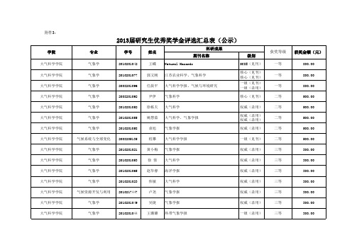
自然地理学 自然地理学 大气物理学与大气环境 大气遥感科学与技术 雷电科学与技术 大气物理学与大气环境 大气物理学与大气环境 大气遥感科学与技术 大气遥感科学与技术 雷电科学与技术 大气物理学与大气环境 大气物理学与大气环境 大气物理学与大气环境 大气物理学与大气环境 大气物理学与大气环境 大气遥感科学与技术 大气遥感科学与技术 雷电科学与技术 雷电科学与技术 系统分析与集成 系统理论 系统理论 系统分析与集成
核心、核心、 省级
二等
500.00
核心、核心 核心、核心 核心、省级 核心、核心 核心、核心 核心、EI会议
三等 三等 三等 三等 三等 三等
300.00 300.00 300.00 300.00 300.00 300.00
信息与控制学院
系统理论
2010214394
曹健
核心、核心、 核心 权威/EI检索 SCI EI 中文核心 中文核心 中文核心 中文核心 中文核心 中文核心 科技核心 中文核心
500.00 500.00 300.00 300.00 300.00 300.00 300.00 500.00 300.00 300.00 800.00 500.00
MMA745xL:三轴数字输出加速度传感器

MMA745xL:三轴数字输出加速度传感器
佚名
【期刊名称】《世界电子元器件》
【年(卷),期】2010(000)009
【摘要】@@ 飞思卡尔推出MMA745xL系列,这是一款数字输出(I2C/SPI)、低功耗、紧凑型电容式微机械加速度计,具有信号调理、低通滤波器、温度补偿、自测、可配置通过中断引脚(INT1或INT2)检测Og、脉冲检测(用于快速运动检测)等功能.Og偏置和灵敏度是出厂配置,无需外部器件.客户可使用指定的Og寄存器和g-Select量程选择对Og偏置进行校准,量程可通过命令选择3个加速度范围
(2g/4g/8g).MMA745xL系列具备待机模式,使它成为以电池为电源的手持式电子
器件的理想选择.
【总页数】1页(P28)
【正文语种】中文
【相关文献】
1.数字输出三轴加速计 [J],
2.全球体积最小、功耗最低的三轴数字输出角速率传感器开始批量生产 [J],
3.美国模拟器件上市支持13bit数字输出的3轴加速度传感器 [J],
4.士兰微电子推出三轴加速度传感器和三轴磁传感器 [J],
5.支持16bit数字输出的3轴加速度传感器 [J],
因版权原因,仅展示原文概要,查看原文内容请购买。
模块介绍集锦
14.步进(直流)电机驱动
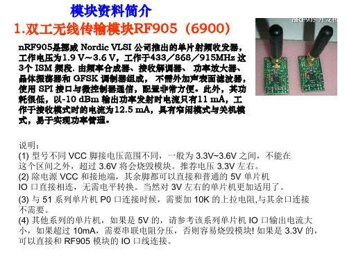
模块资料简介
14.步进(直流)电机驱动
电路原理图
模块资料简介
15.超声测距模块
模块资料简介
16.中文语音合成模块TN6288
模块资料简介
TN6288 天龙TTS迷你串口语音合成模块 免录Arduino机器人直接说话
17.语音模块下载器
模块资料简介
TN6288+ 天龙TTS语音合成模块 USB迷你评估套件(不含喇叭)
30.其他模块
模块资料简介
2262/2272四路无线遥控套件M4非锁接收板 配四键无线遥控器
30.其他模块
模块资料简介
电子防丢器-儿童宠物防走失-钱包行李防盗器-防盗器无线寻物器
5.DC-DC升压模块(0.9V~5V)
模块资料简介
1.输入0.9V~5V任意直流电压,均可稳定输出5V 直流电压,用单节AA电池供电即可输出高达 200~300MA的电流,两节AA电池供电即可输出 500~600MA的电流,可为手机、相机、单片机及 数码产品供电 2.转换效率高,最高达96% 3.带工作指示灯
模块资料简介
XL24LE1是NRF24L01的升级板,是为超低功耗无 线应用设计的单片无线收发系统, 内嵌高性能微处理 器的射频收发单芯片������ 还有16KBFlash 存储器, 1KB数据空间(片内RAM),1KB NV������ 非易失存 储器空间, 512������ 字节 NV������ 非易失数据存储, 低功耗振荡器,实时计数器,AES������ 硬件加密 等 模块功能,以及为低功耗设计的多种电源模式,支 持硬件调试,NRF24LE1������ 提供了一个理想的无 线协议平台,具有协议的无缝连接,高安全性,低 功耗以及搞抗干扰的优良性能。 模块大小21*17mm,1.27.0mm 间距的双排插针 接口,使用内置PCB 天线设计,开阔地2M 速率下, 测试距离最远约50 米左右。
常见i2c设备地址
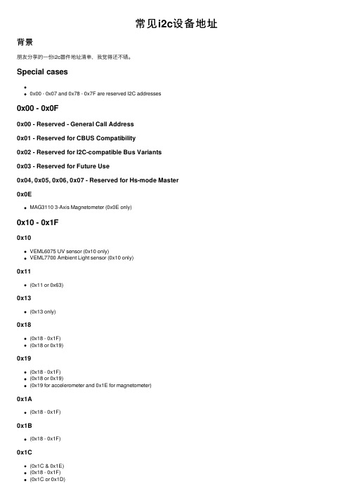
常见i2c设备地址背景朋友分享的⼀份i2c器件地址清单,我觉得还不错。
Special cases0x00 - 0x07 and 0x78 - 0x7F are reserved I2C addresses0x00 - 0x0F0x00 - Reserved - General Call Address0x01 - Reserved for CBUS Compatibility0x02 - Reserved for I2C-compatible Bus Variants0x03 - Reserved for Future Use0x04, 0x05, 0x06, 0x07 - Reserved for Hs-mode Master0x0EMAG3110 3-Axis Magnetometer (0x0E only)0x10 - 0x1F0x10VEML6075 UV sensor (0x10 only)VEML7700 Ambient Light sensor (0x10 only)0x11(0x11 or 0x63)0x13(0x13 only)0x18(0x18 - 0x1F)(0x18 or 0x19)0x19(0x18 - 0x1F)(0x18 or 0x19)(0x19 for accelerometer and 0x1E for magnetometer)0x1A(0x18 - 0x1F)0x1B(0x18 - 0x1F)0x1C(0x1C & 0x1E)(0x18 - 0x1F)(0x1C or 0x1D)(0x1C, 0x1D, 0x1E or 0x1F)MMA7455L (0x1C or 0x1D)0x1D(0x18 - 0x1F)(0x1C or 0x1D)(0x1C, 0x1D, 0x1E or 0x1F)(0x1D or 0x1E for Accel/Mag, 0x6A or 0x6B for Gyro) (0x1D or 0x53)MMA7455L (0x1C or 0x1D)0x1E(0x1C, 0x1D, 0x1E or 0x1F)(0x1E only)(0x1E only)(0x1C & 0x1E)(0x19 for accelerometer and 0x1E for magnetometer) (0x1D or 0x1E for Accel/Mag, 0x6A or 0x6B for Gyro) (0x18 - 0x1F)0x1F(0x18 - 0x1F)(0x1C, 0x1D, 0x1E or 0x1F)0x20-0x2F0x20(0x20 or 0x21)(0x20)(0x20 - 0x27)(0x20 - 0x27)0x21(0x20 or 0x21)(0x20 - 0x27)(0x20 - 0x27)0x22(0x20 - 0x27)(0x20 - 0x27)0x23(0x20 - 0x27)(0x20 - 0x27)0x24(0x20 - 0x27)(0x20 - 0x27)0x25(0x20 - 0x27)(0x20 - 0x27)0x26(0x20 - 0x27)(0x20 - 0x27)(0x26 only)0x27(0x20 - 0x27)(0x20 - 0x27)0x28(0x28 or 0x29)(0x28 - 0x2D)(0x28-0x2B)(0x28-0x2B)(0x28-0x2E, 0x48-0x4F, 0x70-0x77)(0x29 and 0x28)0x29(0x28 or 0x29)(0x28-0x2B)(0x28-0x2B)(0x28-0x2E, 0x48-0x4F, 0x70-0x77)(0x29 only)light sensor (0x29, 0x39 or 0x49)(0x29 and 0x28)ToF distance (0x29, software selectable)(0x29)(0x28 - 0x2D )0x2A(0x28 - 0x2D)(0x28-0x2B)(0x28-0x2B)(0x28-0x2E, 0x48-0x4F, 0x70-0x77)0x2B(0x28 - 0x2D)(0x28-0x2B)(0x28-0x2B)(0x28-0x2E, 0x48-0x4F, 0x70-0x77)0x2C(0x28 - 0x2D)(0x28-0x2E, 0x48-0x4F, 0x70-0x77)0x2D(0x28 - 0x2D)( (0x28-0x2E, 0x48-0x4F, 0x70-0x77)0x2E(0x28-0x2E, 0x48-0x4F, 0x70-0x77)0x30 - 0x3F0x33(0x33 only)0x38(0x38 and 0x39)(0x38 only)0x39(0x29, 0x39 or 0x49)(0x38 and 0x39)APDS-9960 IR/Color/Proximity Sensor (0x39 only)0x3C(0x3C or 0x3D, hardware selectable on some displays with a solder connection) (0x3C or 0x3D, hardware selectable on some displays with a solder connection) 0x3D(0x3C or 0x3D, hardware selectable on some displays with a solder connection) (0x3C or 0x3D, hardware selectable on some displays with a solder connection) 0x40 - 0x4F0x40(0x40 only)(0x40, 0x41, 0x42 or 0x43)(0x40 - 0x47)(0x40 - 0x47)(0x40 - 0x7F)(0x40 - 0x4F)(0x40 - 0x4F)0x41(0x40, 0x41, 0x42 or 0x43)(0x40 - 0x47)(0x40 - 0x47)(0x40 - 0x4F)(0x40 - 0x4F)(0x41 or 0x44)0x42(0x40, 0x41, 0x42 or 0x43)(0x40 - 0x47)(0x40 - 0x47)(0x40 - 0x4F)0x43(0x40, 0x41, 0x42 or 0x43)(0x40 - 0x47)(0x40 - 0x47)(0x40 - 0x4F)(0x40 - 0x4F)0x44(0x40 - 0x47)(0x40 - 0x47)ISL29125 Color Sensor (0x44 only)(0x40 - 0x4F)(0x40 - 0x4F)(0x41 or 0x44)0x45(0x40 - 0x47)(0x40 - 0x47)(0x40 - 0x4F)(0x40 - 0x4F)0x46(0x40 - 0x47)(0x40 - 0x47)(0x40 - 0x4F)(0x40 - 0x4F)0x47(0x40 - 0x47)(0x40 - 0x47)(0x40 - 0x4F)(0x40 - 0x4F)0x48(0x48 0x49 0x4A or 0x4B)(0x40 - 0x4F)(0x40 - 0x4F)(0x28-0x2E, 0x48-0x4F, 0x70-0x77)(0x48 only)TMP102 Temperature sensor (0x48 0x49 0x4A or 0x4B) 0x49(0x48 0x49 0x4A or 0x4B)(0x40 - 0x4F)(0x40 - 0x4F)(0x28-0x2E, 0x48-0x4F, 0x70-0x77)(0x29, 0x39 or 0x49)TMP102 Temperature sensor (0x48 0x49 0x4A or 0x4B) 0x4A(0x48 0x49 0x4A or 0x4B)(0x40 - 0x4F)(0x40 - 0x4F)(0x28-0x2E, 0x48-0x4F, 0x70-0x77)TMP102 Temperature sensor (0x48 0x49 0x4A or 0x4B) 0x4BTMP102 Temperature sensor (0x48 0x49 0x4A or 0x4B) (0x48 0x49 0x4A or 0x4B)(0x40 - 0x4F)(0x40 - 0x4F)(0x28-0x2E, 0x48-0x4F, 0x70-0x77)0x4C(0x40 - 0x4F)(0x40 - 0x4F)(0x28-0x2E, 0x30-0x37, 0x48-0x4F)0x4D(0x40 - 0x4F)(0x40 - 0x4F)(0x28-0x2E, 0x48-0x4F, 0x70-0x77)0x4E(0x40 - 0x4F)(0x40 - 0x4F)(0x28-0x2E, 0x48-0x4F, 0x70-0x77)0x4F(0x40 - 0x4F)(0x40 - 0x4F)(0x28-0x2E, 0x48-0x4F, 0x70-0x77)0x50 - 0x5F0x50(0x50 - 0x57)0x51(0x50 - 0x57)0x52(0x50 - 0x57)(0x52 only)0x53(0x1D or 0x53)(0x50 - 0x57)0x54(0x50 - 0x57)0x55(0x50 - 0x57)0x56(0x50 - 0x57)0x57(0x50 - 0x57)MAX3010x Pulse & Oximetry sensor (0x57) 0x58(0x58 only)SGP30 Gas Sensor (0x58 only)0x5A(0x5A, 0x5B, 0x5C, 0x5D)CCS811 VOC sensor (0x5A or 0x5B)(0x5A only)(0x5A only)0x5B(0x5A, 0x5B, 0x5C, 0x5D)CCS811 VOC sensor (0x5A or 0x5B)0x5C(0x5A, 0x5B, 0x5C, 0x5D)0x5D(0x5A, 0x5B, 0x5C, 0x5D)0x5E(0x5E)0x60 - 0x6F0x60(0x60 or 0x61)(0x60 only)MCP4725A0 12-bit DAC (0x60 or 0x61)TEA5767 Radio receiver (0x60 only)(0x60 only)0x61(0x60 or 0x61)MCP4725A0 12-bit DAC (0x60 or 0x61)0x62(0x62 or 0x63)0x63(0x62 or 0x63)(0x11 or 0x63)0x64MCP4725A2 12-bit DAC (0x64 or 0x65)0x65MCP4725A2 12-bit DAC (0x64 or 0x65)0x66MCP4725A3 12-bit DAC (0x66 or 0x67)0x67MCP4725A3 12-bit DAC (0x66 or 0x67)0x68This address is really popular with real time clocks, almost all of them use 0x68!(0x68 or 0x69)ITG3200 Gyro (0x68 or 0x69)MPU-9250 9-DoF IMU (0x68 or 0x69)MPU-60X0 Accel+Gyro (0x68 or 0x69)0x69(0x68 or 0x69)MPU-9250 (0x68 or 0x69)MPU-60X0 Accel+Gyro (0x68 or 0x69)ITG3200 Gyro (0x68 or 0x69)0x6A(0x6A or 0x6B)(0x6A or 0x6B)(0x6A or 0x6B)(0x6A or 0x6B)(0x1D or 0x1E for Accel/Mag, 0x6A or 0x6B for Gyro) 0x6B(0x6A or 0x6B)(0x6A or 0x6B)(0x6A or 0x6B)(0x6A or 0x6B)(0x1D or 0x1E for Accel/Mag, 0x6A or 0x6B for Gyro) 0x70 - 0x7F0x70(0x70 - 0x77)(0x28-0x2E, 0x48-0x4F, 0x70-0x77)(0x70 - 0x77)0x71(0x70 - 0x77)(0x28-0x2E, 0x48-0x4F, 0x70-0x77)(0x70 - 0x77)0x72(0x70 - 0x77)(0x28-0x2E, 0x48-0x4F, 0x70-0x77)(0x70 - 0x77)0x73(0x70 - 0x77)(0x28-0x2E, 0x48-0x4F, 0x70-0x77)(0x70 - 0x77)0x74(0x70 - 0x77)(0x74 0x75 0x66 or 0x77)(0x28-0x2E, 0x48-0x4F, 0x70-0x77)(0x70 - 0x77)0x75(0x70 - 0x77)(0x74 0x75 0x66 or 0x77)(0x28-0x2E, 0x48-0x4F, 0x70-0x77)(0x70 - 0x77)0x76(0x70 - 0x77)(0x74 0x75 0x66 or 0x77)MS5607/MS5611 Barometric Pressure (0x76 or 0x77)(0x28-0x2E, 0x48-0x4F, 0x70-0x77)(0x70 - 0x77)0x77BMA180 Accelerometer (0x77 only)(0x70 - 0x77)(0x74 0x75 0x66 or 0x77)MS5607/MS5611 Barometric Pressure (0x76 or 0x77)(0x28-0x2E, 0x48-0x4F, 0x70-0x77)(0x70 - 0x77)0x78 0x79 0x7A 0x7B - Reserved for 10-bit I2C Addressing 0x7C 0x7D 0x7E 0x7F - Reserved for Future Purposes。
基于MMA7455的抽油机加速度信息采集系统

1 引 言
机 井 抽 油 是 石 油 生 产 中最 重 要 的 工 艺 过 程 之 ~ , 时 及
G R P S通 讯 模 块 上 传 到 Itre 上 , 上 位 机 下 载 、 储 数 nen t 供 存
据, 并利用油井信息解释软件处理获取油井示功 图。
!= : : : : : 一 : : : 二 : : 一 .: 二 : : 一 : : : : : 一 一 : : : : : 一 一 : : : _ _ =
i传器 委 l 感
一 一 一 ::;
- _
:
信i> b\ 号N fi / I g e 面a Ze:
:--
- - - - - _
匝 圈
- -
_
;- - - - ;:: -
一
的重点就是通过 MMA75 加 速度传感器获取 油井工作状 45
况 的数 据 , 而 得 出 油 井 示 功 图 , 过 诊 断 技 术 处 理 , 以 进 经 可 找 出影 响 油 井 泵 效 或 不 出 油 的 原 因 , 后 根 据 油 田 采 油 工 然
本 系统 采 用 M MA7 5 1 飞 思 卡 尔 公 司 ) 字 三 轴 加 4 5 ( 数 速度传 感器来 测量 抽油 机 运动 的加 速度 , MMA7 5 4 5是 一 款 数 字 输 出 (2 / P ) 低 功 耗 、 凑 型 电 容 式 微 机 械 加 速 IC S I 、 紧 度计 , 有信号调理 、 通滤 波器 、 度补偿 、 具 低 温 自测 、 及 脉 以 冲检 测 ( 于 快 速 运 动 检 测 ) 功 能 。如 图 2即 为 加 速 度 硬 用 等
2 系统 整体 设 计
为了有效地 采集 抽油机工作状 况并 实现数据 的远 程传 输, 本系统必须具备油 井数 据 自动 采集 、 远程 传输 、 存储 管 理、 网络发布 、 分析处理等功能 。从 逻辑结构上将 系统 划分 为三大子系统 : 安装在现场 的数据采集与远程 传输子系统 、
基于52单片机的智能手环设计与实现

基于52单片机的智能手环设计与实现摘要:随科技与信息技术的发展。
制作芯片技术的逐渐成熟使得元器件生产成本也逐渐下降。
因而改变我们生活的科技产品不但数量多,且具备智能特点。
在生活中,人们闲暇时间常去健身。
而监测自己身体状况、制定健身计划、确保健身时人身安全成为难题。
生活中普遍的监测设备笨重且操作复杂。
因而希望有产品可以随身携带监测健康安全。
众所周知,设备体积小又精密,价格也会相应的昂贵。
也使的这类监测产品难以有效的得到普及并运用到生活中。
本次设计是基于52单片机的智能手环设计与实现,以52单片机为主控核心模板,采用Pulse Sensor 脉搏传感器监测心率,采用DS18B20温度传感器监测温度,采用MPU6050陀螺仪采集行走步数。
采集到基本数据后经STC89C52单片机处理转换再通过LCD1602液晶屏显示。
同时也具备按键设定阈值的功能,当监测数据超过阈值时,系统会触发蜂鸣器实现声音报警提示人体发生异常的功能。
关键词:52单片机、健康、心率、体温、手环Design and implementation of intelligent Bracelet based on 52single chip microcompute rAbstract:With the development of technology and information technology. The gradual maturity of chip manufacturing technology has gradually reduced the production cost of components. As a result, not only are there a large number of technology products that change our lives, they are also intelligent. In life, people often go to fitness in their free time. However, monitoring one's physical condition, formulating a fitness plan, and ensuring personal safety during fitness have become difficult. The common monitoring equipment in life is heavy and complicated to operate. It is therefore hoped that some products can be carried around to monitor health and safety. As we all know, the equipment is small and precise, and the price will be correspondingly expensive. It also makes it difficult for such monitoring products to be effectively popularized and used in life.This design is based on the design and implementation of a smart bracelet based on 52 single-chip microcomputer, using 52 single-chip microcomputer as the core template, pulse sensor to monitor heart rate, DS18B20 temperature sensor to monitor temperature, and MPU6050 gyroscope to collect walking steps. After collecting the basic data, it is processed and converted by the STC89C52 single-chip microcomputer and then displayed through the LCD1602 liquid crystal screen. At the same time, it also has the function of setting the threshold by key. When the monitoring data exceeds the threshold, the system will trigger the buzzer to realize the function of sound alarm to remind the human body of abnormality.Keywords: 52 single chip microcomputer, health, heart rate, body temperature, bracelet目录第1章绪论 (1)1.1研究背景和意义 (1)1.1.1基于52单片机的需求分析 (1)1.1.2 本课题的研究意义 (2)1.2 设计的主要任务与目标 (2)1.2.1 设计的主要任务 (2)1.2.2 设计的最终目标 (2)1.3开发工具 (3)1.4本章小结 ..................................................................................................... 错误!未定义书签。
- 1、下载文档前请自行甄别文档内容的完整性,平台不提供额外的编辑、内容补充、找答案等附加服务。
- 2、"仅部分预览"的文档,不可在线预览部分如存在完整性等问题,可反馈申请退款(可完整预览的文档不适用该条件!)。
- 3、如文档侵犯您的权益,请联系客服反馈,我们会尽快为您处理(人工客服工作时间:9:00-18:30)。
Document Number: MMA7455LRev 10, 12/2009Freescale SemiconductorTechnical DataThis document contains certain information on a new product.Specifications and information herein are subject to change without notice.±2g/±4g/±8g Three Axis Low-g Digital Output AccelerometerThe MMA7455L is a Digital Output (I 2C/SPI), low power, low profilecapacitive micromachined accelerometer featuring signal conditioning, a low pass filter, temperature compensation, self-test, configurable to detect 0g through interrupt pins (INT1 or INT2), and pulse detect for quick motion detection. 0g offset and sensitivity are factory set and require no external devices. The 0g offset can be customer calibrated using assigned 0g registers and g-Select which allows for command selection for 3 acceleration ranges (2g/4g/8g). The MMA7455L includes a Standby Mode that makes it ideal for handheld battery powered electronics.Features •Digital Output (I 2C/SPI)•3mm x 5mm x 1mm LGA-14 Package •Self-Test for Z-Axis•Low Voltage Operation: 2.4 V – 3.6 V•User Assigned Registers for Offset Calibration •Programmable Threshold Interrupt Output•Level Detection for Motion Recognition (Shock, Vibration, Freefall)•Pulse Detection for Single or Double Pulse Recognition •Sensitivity (64 LSB/g @ 2g and @ 8g in 10-Bit Mode)•Selectable Sensitivity (±2g, ±4g, ±8g) for 8-bit Mode •Robust Design, High Shocks Survivability (5,000g)•RoHS Compliant•Environmentally Preferred Product •Low CostTypical Applications •Cell Phone/PMP/PDA: Image Stability, Text Scroll, Motion Dialing,Tap to Mute•HDD: Freefall Detection•Laptop PC: Freefall Detection, Anti-Theft •Pedometer•Motion Sensing, Event RecorderORDERING INFORMATIONPart Number Temperature RangePackage Shipping MMA7455LT –40 to +85°C LGA-14Tray MMA7455LR1–40 to +85°C LGA-147” Tape & Reel MMA7455LR2–40 to +85°CLGA-1413” Tape & ReelMMA7455LMMA7455L: XYZ-AXIS ACCELEROMETER±2g/±4g/±8g14 LEAD LGACASE 1977-01Bottom ViewContentsELECTRO STATIC DISCHARGE (ESD) (6)PRINCIPLE OF OPERATION (8)FEATURES (9)Self-Test (9)g-Select (9)Standby Mode (9)Measurement Mode (9)LEVEL DETECTION (10)$18: Control 1 (Read/Write) Setting the Detection Axes for X, Y and Z (10)$19: Control 2 (Read/Write) Motion Detection (OR Condition) or Freefall Detection (AND Condition) (10)$18: Control 1 (Read/Write): Setting the threshold to be an integer value or an absolute value (10)$1A: Level Detection Threshold Limit Value (Read/Write) (10)THRESHOLD DETECTION FOR MOTION AND FREEFALL CONDITIONS (11)CASE 1: Motion Detection (11)CASE 2: Motion Detection (11)CASE 3: Freefall Detection (11)CASE 4: Freefall Detection (11)PULSE DETECTION (12)$18: Control 1 (Read/Write): Disable X, Y or Z for Pulse Detection (12)$19: Control 2 (Read/Write): Motion Detection (OR condition) or Freefall Detection (AND condition) (12)CASE 1: Single Pulse Motion Detection: X or Y or Z > Pulse Threshold for Time < Pulse Duration (12)CASE 2: Freefall Detection: X and Y and Z < Pulse Threshold for Time > Latency Time (13)CASE 3: Double Pulse Detection: X OR Y OR Z > Threshold for Pulse Duration1 < PDTime1, Latency Time, (14)ASSIGNING, CLEARING & DETECTING INTERRUPTS (15)Clearing the Interrupt Pins: Register $17 (15)Detecting Interrupts (16)DIGITAL INTERFACE (16)I2C Slave Interface (16)SPI Slave Interface (18)BASIC CONNECTIONS (19)Pin Descriptions (19)Recommended PCB Layout for Interfacing Accelerometer to Microcontroller (19)REGISTER DEFINITIONS (21)SOLDERING AND MOUNTING GUIDELINES FOR THE LGA ACCELEROMETER SENSOR TO A PC BOARD (29)Pin Connections . . . . . . . . . . . . . . . . . . . . . . . . . . . . . . . . . . . . . . . . . . . . . . . . . . . . . . . . . . . . . . . . . . . . . . . . . . . . . . . . . . . . . .1 Simplified Accelerometer Functional Block Diagram . . . . . . . . . . . . . . . . . . . . . . . . . . . . . . . . . . . . . . . . . . . . . . . . . . . . . . . . . .5 Simplified Transducer Physical Model . . . . . . . . . . . . . . . . . . . . . . . . . . . . . . . . . . . . . . . . . . . . . . . . . . . . . . . . . . . . . . . . . . . . .8 Single Pulse Detection . . . . . . . . . . . . . . . . . . . . . . . . . . . . . . . . . . . . . . . . . . . . . . . . . . . . . . . . . . . . . . . . . . . . . . . . . . . . . . . .13 Freefall Detection in Pulse Mode . . . . . . . . . . . . . . . . . . . . . . . . . . . . . . . . . . . . . . . . . . . . . . . . . . . . . . . . . . . . . . . . . . . . . . . .13 Double Pulse Detection . . . . . . . . . . . . . . . . . . . . . . . . . . . . . . . . . . . . . . . . . . . . . . . . . . . . . . . . . . . . . . . . . . . . . . . . . . . . . . .14 Single Byte Read - The Master is reading one address from the MMA7455L . . . . . . . . . . . . . . . . . . . . . . . . . . . . . . . . . . . . . 17 Multiple Bytes Read - The Master is reading multiple sequential registers from the MMA7455L . . . . . . . . . . . . . . . . . . . . . . .17 Single Byte Write - The Master (MCU) is writing to a single register of the MMA7455L . . . . . . . . . . . . . . . . . . . . . . . . . . . . . .17 Multiple Byte Writes - The Master (MCU) is writing to multiple sequential registers of the MMA7455L . . . . . . . . . . . . . . . . . . .17 SPI Timing Diagram for 8-Bit Register Read (4 Wire Mode) . . . . . . . . . . . . . . . . . . . . . . . . . . . . . . . . . . . . . . . . . . . . . . . . . . .18 SPI Timing Diagram for 8-Bit Register Read (3 Wire Mode) . . . . . . . . . . . . . . . . . . . . . . . . . . . . . . . . . . . . . . . . . . . . . . . . . . .18 SPI Timing Diagram for 8-Bit Register Write (3 Wire Mode) . . . . . . . . . . . . . . . . . . . . . . . . . . . . . . . . . . . . . . . . . . . . . . . . . . .18 Pinout Description . . . . . . . . . . . . . . . . . . . . . . . . . . . . . . . . . . . . . . . . . . . . . . . . . . . . . . . . . . . . . . . . . . . . . . . . . . . . . . . . . . .19 I2C Connection to MCU . . . . . . . . . . . . . . . . . . . . . . . . . . . . . . . . . . . . . . . . . . . . . . . . . . . . . . . . . . . . . . . . . . . . . . . . . . . . . . .19 SPI Connection to MCU . . . . . . . . . . . . . . . . . . . . . . . . . . . . . . . . . . . . . . . . . . . . . . . . . . . . . . . . . . . . . . . . . . . . . . . . . . . . . . .20 Sensing Direction and Output Response at 2g Mode . . . . . . . . . . . . . . . . . . . . . . . . . . . . . . . . . . . . . . . . . . . . . . . . . . . . . . . .28 Recommended PCB Land Pattern for the 5 x 3 mm LGA Package . . . . . . . . . . . . . . . . . . . . . . . . . . . . . . . . . . . . . . . . . . . . . .29 Incorrect PCB Top Metal Pattern Under Package . . . . . . . . . . . . . . . . . . . . . . . . . . . . . . . . . . . . . . . . . . . . . . . . . . . . . . . . . . .30 Correct PCB Top Metal Pattern Under Package . . . . . . . . . . . . . . . . . . . . . . . . . . . . . . . . . . . . . . . . . . . . . . . . . . . . . . . . . . . .30 Recommended PCB Land Pad, Solder Mask, and Signal Trace Near Package Design . . . . . . . . . . . . . . . . . . . . . . . . . . . . . .30 Stencil Design Guidelines . . . . . . . . . . . . . . . . . . . . . . . . . . . . . . . . . . . . . . . . . . . . . . . . . . . . . . . . . . . . . . . . . . . . . . . . . . . . . .31 Temperature Coefficient of Offset (TCO) and Temperature Coefficient of Sensitivity (TCS) Distribution Charts . . . . . . . . . . .32 MMA7455L Current Distribution Charts . . . . . . . . . . . . . . . . . . . . . . . . . . . . . . . . . . . . . . . . . . . . . . . . . . . . . . . . . . . . . . . . . . .32Pin Descriptions . . . . . . . . . . . . . . . . . . . . . . . . . . . . . . . . . . . . . . . . . . . . . . . . . . . . . . . . . . . . . . . . . . . . . . . . . . . . . . . . . . . . . .5 Maximum Ratings . . . . . . . . . . . . . . . . . . . . . . . . . . . . . . . . . . . . . . . . . . . . . . . . . . . . . . . . . . . . . . . . . . . . . . . . . . . . . . . . . . . . 6 Operating Characteristics . . . . . . . . . . . . . . . . . . . . . . . . . . . . . . . . . . . . . . . . . . . . . . . . . . . . . . . . . . . . . . . . . . . . . . . . . . . . . . 8 $16: Mode Control Register (Read/Write). . . . . . . . . . . . . . . . . . . . . . . . . . . . . . . . . . . . . . . . . . . . . . . . . . . . . . . . . . . . . . . . . . 9 Configuring the g-Select for 8-bit output using Register $16 with GLVL[1:0] bits . . . . . . . . . . . . . . . . . . . . . . . . . . . . . . . . . . . . .9 Configuring the Mode using Register $16 with MODE[1:0] bits . . . . . . . . . . . . . . . . . . . . . . . . . . . . . . . . . . . . . . . . . . . . . . . . . .9 THOPT = 0 Absolute; THOPT = 1 Positive Negative . . . . . . . . . . . . . . . . . . . . . . . . . . . . . . . . . . . . . . . . . . . . . . . . . . . . . . . . .10 $1B: Pulse Detection Threshold Limit Value (Read/Write) . . . . . . . . . . . . . . . . . . . . . . . . . . . . . . . . . . . . . . . . . . . . . . . . . . . . .12 $1C: Pulse Duration Value (Read/Write) . . . . . . . . . . . . . . . . . . . . . . . . . . . . . . . . . . . . . . . . . . . . . . . . . . . . . . . . . . . . . . . . . .12 $1B: Pulse Detection Threshold Limit Value (Read/Write) . . . . . . . . . . . . . . . . . . . . . . . . . . . . . . . . . . . . . . . . . . . . . . . . . . . . .13 $1D: Latency Time Value (Read/Write) . . . . . . . . . . . . . . . . . . . . . . . . . . . . . . . . . . . . . . . . . . . . . . . . . . . . . . . . . . . . . . . . . . .13 $1B: Pulse Detection Threshold Limit Value (Read/Write) . . . . . . . . . . . . . . . . . . . . . . . . . . . . . . . . . . . . . . . . . . . . . . . . . . . . .14 $1C: Pulse Duration Value (Read/Write) . . . . . . . . . . . . . . . . . . . . . . . . . . . . . . . . . . . . . . . . . . . . . . . . . . . . . . . . . . . . . . . . . .14 $1D: Latency Time Value (Read/Write) . . . . . . . . . . . . . . . . . . . . . . . . . . . . . . . . . . . . . . . . . . . . . . . . . . . . . . . . . . . . . . . . . . .14 $1E: Time Window for 2nd Pulse Value (Read/Write) . . . . . . . . . . . . . . . . . . . . . . . . . . . . . . . . . . . . . . . . . . . . . . . . . . . . . . . .14 $18 Control 1 Register . . . . . . . . . . . . . . . . . . . . . . . . . . . . . . . . . . . . . . . . . . . . . . . . . . . . . . . . . . . . . . . . . . . . . . . . . . . . . . . .15 Configuring the Interrupt settings using Register $18 with INTREG[1:0] bits . . . . . . . . . . . . . . . . . . . . . . . . . . . . . . . . . . . . . . .15 $17: Interrupt Latch Reset (Read/Write) . . . . . . . . . . . . . . . . . . . . . . . . . . . . . . . . . . . . . . . . . . . . . . . . . . . . . . . . . . . . . . . . . . .15 $0A: Detection Source Register (Read only) . . . . . . . . . . . . . . . . . . . . . . . . . . . . . . . . . . . . . . . . . . . . . . . . . . . . . . . . . . . . . . .16 Pin Descriptions . . . . . . . . . . . . . . . . . . . . . . . . . . . . . . . . . . . . . . . . . . . . . . . . . . . . . . . . . . . . . . . . . . . . . . . . . . . . . . . . . . . . .19 User Register Summary . . . . . . . . . . . . . . . . . . . . . . . . . . . . . . . . . . . . . . . . . . . . . . . . . . . . . . . . . . . . . . . . . . . . . . . . . . . . . . .21 $00: 10bits Output Value X LSB (Read only) . . . . . . . . . . . . . . . . . . . . . . . . . . . . . . . . . . . . . . . . . . . . . . . . . . . . . . . . . . . . . . .21 $01: 10bits Output Value X MSB (Read only) . . . . . . . . . . . . . . . . . . . . . . . . . . . . . . . . . . . . . . . . . . . . . . . . . . . . . . . . . . . . . .22 $02: 10bits Output Value Y LSB (Read only) . . . . . . . . . . . . . . . . . . . . . . . . . . . . . . . . . . . . . . . . . . . . . . . . . . . . . . . . . . . . . . .22 $03: 10bits Output Value Y MSB (Read only) . . . . . . . . . . . . . . . . . . . . . . . . . . . . . . . . . . . . . . . . . . . . . . . . . . . . . . . . . . . . . .22 $05: 10bits Output Value X MSB (Read only) . . . . . . . . . . . . . . . . . . . . . . . . . . . . . . . . . . . . . . . . . . . . . . . . . . . . . . . . . . . . . .22 $06: 8bits Output Value X (Read only) . . . . . . . . . . . . . . . . . . . . . . . . . . . . . . . . . . . . . . . . . . . . . . . . . . . . . . . . . . . . . . . . . . . .22 $07: 8bits Output Value Y (Read only) . . . . . . . . . . . . . . . . . . . . . . . . . . . . . . . . . . . . . . . . . . . . . . . . . . . . . . . . . . . . . . . . . . . .22 $08: 8bits Output Value Z (Read only) . . . . . . . . . . . . . . . . . . . . . . . . . . . . . . . . . . . . . . . . . . . . . . . . . . . . . . . . . . . . . . . . . . . .23 $09: Status Register (Read only) . . . . . . . . . . . . . . . . . . . . . . . . . . . . . . . . . . . . . . . . . . . . . . . . . . . . . . . . . . . . . . . . . . . . . . . .23 $0A: Detection Source Register (Read only) . . . . . . . . . . . . . . . . . . . . . . . . . . . . . . . . . . . . . . . . . . . . . . . . . . . . . . . . . . . . . . .23 $0D: I2C Device Address (Bit 6-0: Read only, Bit 7: Read/Write) . . . . . . . . . . . . . . . . . . . . . . . . . . . . . . . . . . . . . . . . . . . . . . .23 $0E: User Information (Read Only: Optional) . . . . . . . . . . . . . . . . . . . . . . . . . . . . . . . . . . . . . . . . . . . . . . . . . . . . . . . . . . . . . . .23 $0F: “Who Am I” Value (Read only: Optional) . . . . . . . . . . . . . . . . . . . . . . . . . . . . . . . . . . . . . . . . . . . . . . . . . . . . . . . . . . . . . .24 $10: Offset Drift X LSB (Read/Write) . . . . . . . . . . . . . . . . . . . . . . . . . . . . . . . . . . . . . . . . . . . . . . . . . . . . . . . . . . . . . . . . . . . . .24 $11: Offset Drift X MSB (Read/Write) . . . . . . . . . . . . . . . . . . . . . . . . . . . . . . . . . . . . . . . . . . . . . . . . . . . . . . . . . . . . . . . . . . . . .24 $12: Offset Drift Y LSB (Read/Write) . . . . . . . . . . . . . . . . . . . . . . . . . . . . . . . . . . . . . . . . . . . . . . . . . . . . . . . . . . . . . . . . . . . . .24 $13: Offset Drift Y MSB (Read/Write) . . . . . . . . . . . . . . . . . . . . . . . . . . . . . . . . . . . . . . . . . . . . . . . . . . . . . . . . . . . . . . . . . . . . .24 $14: Offset Drift Z LSB (Read/Write) . . . . . . . . . . . . . . . . . . . . . . . . . . . . . . . . . . . . . . . . . . . . . . . . . . . . . . . . . . . . . . . . . . . . .25 $15: Offset Drift Z MSB (Read/Write) . . . . . . . . . . . . . . . . . . . . . . . . . . . . . . . . . . . . . . . . . . . . . . . . . . . . . . . . . . . . . . . . . . . . .25 $16: Mode Control Register (Read/Write) . . . . . . . . . . . . . . . . . . . . . . . . . . . . . . . . . . . . . . . . . . . . . . . . . . . . . . . . . . . . . . . . .25 Configuring the g-Select for 8-bit output using Register $16 with GLVL[1:0] bits . . . . . . . . . . . . . . . . . . . . . . . . . . . . . . . . . . . .25 Configuring the Mode using Register $16 with MODE[1:0] bits . . . . . . . . . . . . . . . . . . . . . . . . . . . . . . . . . . . . . . . . . . . . . . . . .25 $17: Interrupt Latch Reset (Read/Write) . . . . . . . . . . . . . . . . . . . . . . . . . . . . . . . . . . . . . . . . . . . . . . . . . . . . . . . . . . . . . . . . . . .26 $18 Control 1 (Read/Write) . . . . . . . . . . . . . . . . . . . . . . . . . . . . . . . . . . . . . . . . . . . . . . . . . . . . . . . . . . . . . . . . . . . . . . . . . . . . .26 Configuring the Interrupt settings using Register $18 with INTREG[1:0] bits . . . . . . . . . . . . . . . . . . . . . . . . . . . . . . . . . . . . . . .26 $1B: Pulse Detection Threshold Limit Value (Read/Write) . . . . . . . . . . . . . . . . . . . . . . . . . . . . . . . . . . . . . . . . . . . . . . . . . . . . .27 $1C: Pulse Duration Value (Read/Write) . . . . . . . . . . . . . . . . . . . . . . . . . . . . . . . . . . . . . . . . . . . . . . . . . . . . . . . . . . . . . . . . . .27 $1D: Latency Time Value (Read/Write) . . . . . . . . . . . . . . . . . . . . . . . . . . . . . . . . . . . . . . . . . . . . . . . . . . . . . . . . . . . . . . . . . . .27 $1E: Time Window for 2nd Pulse Value (Read/Write) . . . . . . . . . . . . . . . . . . . . . . . . . . . . . . . . . . . . . . . . . . . . . . . . . . . . . . . .27 $1A: Level Detection Threshold Limit Value (Read/Write) . . . . . . . . . . . . . . . . . . . . . . . . . . . . . . . . . . . . . . . . . . . . . . . . . . . . .27 Acceleration vs. Output (8-bit data) . . . . . . . . . . . . . . . . . . . . . . . . . . . . . . . . . . . . . . . . . . . . . . . . . . . . . . . . . . . . . . . . . . . . . .28Table 1. Pin Descriptions*This address selection capability is not enabled at the default state. If the user wants to use it, factory programming is required. If activated (pin4 on the device is active).<$1D= 0001 1101> bit 0 is V DD on pin 4<$1C=0001 1100> bit 0 is GND on pin 4. If the pin is programmed it cannot be left NC.Figure 2. Simplified Accelerometer Functional Block DiagramPin #Pin NameDescriptionPin Status 1DVDD_IO Digital Power for I/O pads Input2GND GroundInput 3N/C No internal connection. Leave unconnected or connect to Ground.Input 4IADDR0I 2C Address Bit 0 (optional)*Input 5GND Ground Input 6AVDD Analog PowerInput 7CS SPI Enable (0), I 2C Enable (1)Input 8INT1/DRDYInterrupt 1/ Data Ready Output 9INT2Interrupt 2Output 10N/C No internal connection. Leave unconnected or connect to Ground.Input 11N/C Leave unconnected or connect to Ground.Input 12SDO SPI Serial Data OutputOutput13SDA/SDI/SDO I 2C Serial Data (SDA), SPI Serial Data Input (SDI), 3-wire interface Serial Data Output (SDO)Open Drain/Input/Output 14SCL/SPCI 2C Serial Clock (SCL), SPI Serial Clock (SPC)InputELECTRO STATIC DISCHARGE (ESD)WARNING:This device is sensitive to electrostatic discharge.Although the Freescale accelerometer contains internal 2000V ESD protection circuitry, extra precaution must be taken by the user to protect the chip from ESD. A charge of over 2000 volts can accumulate on the human body or associated test equipment. A charge of this magnitude can alter the performance or cause failure of the chip. When handling the accelerometer, proper ESD precautions should be followed to avoid exposing the device to discharges which may be detrimental to its performance.Table 2. Maximum Ratings(Maximum ratings are the limits to which the device can be exposed without causing permanent damage.)RatingSymbol Value Unit Maximum Acceleration (all axes)g max 5000g Analog Supply Voltage AV DD -0.3 to +3.6V Digital I/O pins Supply Voltage DV DD_IO -0.3 to +3.6V Drop TestD drop 1.8m Storage Temperature RangeT stg-40 to +125°CTable 3. Operating CharacteristicsUnless otherwise noted: –40°C < T A < 85°C, 2.4 V < AV DD < 3.6 V, Acceleration = 0g, Loaded output.CharacteristicSymbol MinTyp Max Unit Analog Supply Voltage Standby/Operation Mode Enable Bus ModeDigital I/O Pins Supply Voltage (1)Standby/Operation Mode Enable Bus ModeAV DD AV DD DV DD_IO DV DD_IO2.42.4 2.802.803.63.6V V V VSupply Current Drain Operation ModePulse Detect Function ModeStandby Mode (except data loading and I 2C/SPI communication period)I DD I DD I DD ———4004002.549049010μA μA μA Operating Temperature RangeT A-402585°C0g Output Signal (T A =25°C, AV DD = 2.8 V)±2g range (25°C) 8-bit GLVL[1:0]= 0 1±4g range (25°C) 8-bit GLVL[1:0]= 1 0±8g range (25°C) 8-bit GLVL[1:0]= 0 0±8g range (25°C) 10-bit -18-10-5-1800001810518count count count countSensitivity (T A =25°C, AV DD = 2.8 V)±2g range (25°C) 8-bit ±4g range (25°C) 8-bit ±8g range (25°C) 8-bit ±8g range (25°C) 10-bit 582914.55864321664703517.570count/g count/g count/g count/g Self-Test Output Response ZoutΔST Z 326483count Temperature Compensation for Offset T CO ±3.5±0.5+3.5mg/°C Temperature Sensitivity for Offset T CS ±0.026±0.01+0.026mg/°C Input High Voltage Input Low VoltageV IH V IL 0.7 x DVDD————0.35 x DVDDV V Internal Clock Frequency (T A = 25°C, AV DD = 2.8 V)t CLK140150160kHz SPI Frequency DV DD_IO < 2.4 V DV DD_IO > 2.4 V——48——MHz MHz Bandwidth for Data Measurement (User Selectable)DFBW 0DFBW 1——62.5125——Hz Hz Output Data RateOutput Data Rate is 125 Hz when 62.5 bandwidth is selected.Output Data rate is 250 Hz when 125 Hz bandwidth is selected.——125250——Hz Hz Control TimingWait Time for I 2C/SPI ready after power onTurn On Response Time (Standby to Normal Mode)Turn Off Response Time (Normal to Standby Mode)Self-Test Response TimeSensing Element Resonant Frequency XY Z t su t ru t rd t st f GCELLXY f GCELLZ ——————1———6.03.4—202020——ms ms ms ms kHz kHz Nonlinearity (2 g range)-1—+1%FS Cross Axis Sensitivity-5—+5%1. It is recommended to tie the analog and digital supply voltages together.DD *The bandwidth for detecting interrupts in level and pulse is 600Hz which is changed from measurement mode.PRINCIPLE OF OPERATIONThe Freescale accelerometer is a surface-micromachined integrated-circuit accelerometer. The device consists of a surface mi-cromachined capacitive sensing cell (g-cell) and a signal conditioning ASIC contained in a single package. The sensing element is sealed hermetically at the wafer level using a bulk micromachined cap wafer. The g-cell is a mechanical structure formed from semiconductor materials (polysilicon) using semiconductor processes (masking and etching). It can be modeled as a set of beams attached to a movable central mass that move between fixed beams. The movable beams can be deflected from their rest position by subjecting the system to an acceleration (Figure 3).As the beams attached to the central mass move, the distance from them to the fixed beams on one side will increase by the same amount that the distance to the fixed beams on the other side decreases. The change in distance is a measure of accel-eration. The g-cell beams form two back-to-back capacitors (Figure 3). As the center beam moves with acceleration, the distance between the beams changes and each capacitor's value will change, (C = A ε/D). Where A is the area of the beam, ε is the di-electric constant, and D is the distance between the beams.The ASIC uses switched capacitor techniques to measure the g-cell capacitors and extract the acceleration data from the differ-ence between the two capacitors. The ASIC also signal conditions and filters (switched capacitor) the signal, providing a digital output that is proportional to acceleration.Figure 3. Simplified Transducer Physical ModelTable 4. Function Parameters for Detection–40°C < T A < 85°C, 2.4 V < AV DD < 3.6 V, unless otherwise specifiedCharacteristicSymbolMin Typ Max Unit Level DetectionDetection Threshold Range0—FS g Pulse DetectionPulse detection range (Adjustable range)Time step for pulse detection Threshold range for pulses Detection levels for threshold Latency timer (Adjustable range)Time Window (Adjustable range)Bandwidth for detecting interrupt*Time step for latency timer and time window0.5—0—11———0.5—127——6001127—FS —150250——ms ms g Counts ms ms Hz msAccelerationFEATURESSelf-TestThe sensor provides a self-test feature that allows the verification of the mechanical and electrical integrity of the accelerometer at any time before or after installation. This feature is critical in applications such as hard disk drive protection where system in-tegrity must be ensured over the life of the product. When the self-test function is initiated through the mode control register ($16), accessing the “self-test” bit, an electrostatic force is applied to each axis to cause it to deflect. The Z-axis is trimmed to deflect 1g. This procedure assures that both the mechanical (g-cell) and electronic sections of the accelerometer are functioning.g-SelectThe g-Select feature enables the selection between 3 acceleration ranges for measurement. Depending on the values in the Mode control register ($16), the MMA7455L’s internal gain will be changed allowing it to function with a 2g, 4g or 8g measurement sensitivity. This feature is ideal when a product has applications requiring two or more acceleration ranges for optimum perfor-mance and for enabling multiple functions. The sensitivity can be changed during the operation by modifying the two GLVL bits located in the mode control register.Standby ModeThis digital output 3-axis accelerometer provides a standby mode that is ideal for battery operated products. When standby mode is active, the device outputs are turned off, providing significant reduction of operating current. When the device is in standby mode the current will be reduced to 2.5 µA typical. In standby mode the device can read and write to the registers with the I 2C/SPI available, but no new measurements can be taken in this mode as all current consuming parts are off. The mode of the device is controlled through the mode control register by accessing the two mode bits as shown in Table 6.Measurement ModeThe device can read XYZ measurements in this mode. The pulse and threshold interrupts are not active. During measurement mode, continuous measurements on all three axes enabled. The g-range for 2g, 4g, or 8g are selectable with 8-bit data and the g-range of 8g is selectable with 10-bit data. The sample rate during measurement mode is 125Hz with 62.5 BW filter selected. The sample rate is 250Hz with the 125 Hz filter selected. Therefore, when a conversion is complete (signaled by the DRDY flag), the next measurement will be ready.When measurements on all three axes are completed, a logic high level is output to the DRDY pin, indicating “measurement data is ready.” The DRDY status can be monitored by the DRDY bit in Status Register (Address: $09). The DRDY pin is kept high until one of the three Output Value Registers are read. If the next measurement data is written before the previous data is read, the DOVR bit in the Status Register will be set. Also note that in measurement mode, level detection mode and pulse detection mode are not available.By default all three axes are enabled. X and/or Y and/or Z can be disabled. There is a choice between detecting an absolute signal or a positive or negative only signal on the enabled axes. There is also a choice between doing a detection for motion where X or Y or Z > Threshold vs. doing a detection for freefall where X & Y & Z < Threshold.$16: Mode Control Register (Read/Write)D7D6D5D4D3D2D1D0Bit --DRPDSPI3W STON GLVL[1]GLVL[0]MODE[1]MODE[0]Function 0DefaultTable 5. Configuring the g-Select for 8-bit output using Register $16 with GLVL[1:0] bitsGLVL [1:0]g-Range Sensitivity 008g 16 LSB/g 012g 64 LSB/g 104g32 LSB/gTable 6. Configuring the Mode using Register $16 with MODE[1:0] bitsMODE [1:0]Function 00Standby Mode 01Measurement Mode 10Level Detection Mode 11Pulse Detection ModeLEVEL DETECTIONThe user can access XYZ measurements and can use the level interrupt only. The level detection mechanism has no timers as-sociated with it. Once a set acceleration level is reached the interrupt pin will go high and remain high until the interrupt pin is cleared (See Assigning, Clearing & Detecting Interrupts ).By default all three axes are enabled and the detection range is 8g only. X and/or Y and/or Z can be disabled. There is a choice between detecting an Absolute signal or a Positive or Negative only signal on the enabled axes. There is also a choice between doing a detection for Motion where X or Y or Z > Threshold vs. doing a detection for Freefall where X & Y & Z < Threshold.$18: Control 1 (Read/Write) Setting the Detection Axes for X, Y and ZThis allows the user to define how many axes to use for detection. All axes are enabled by default. To disable write 1. XDA: Disable X YDA: Disable Y ZDA: Disable Z$19: Control 2 (Read/Write) Motion Detection (OR Condition) or Freefall Detection (AND Condition )LDPL = 0: Level detection polarity is positive and detecting condition is OR for all 3 axes.X or Y or Z > Threshold||X|| or ||Y|| or ||Z|| > ThresholdLDPL = 1: Level detection polarity is negative detecting condition is AND for all 3 axes. X and Y and Z < Threshold||X|| and ||Y|| and ||Z|| < Threshold$18: Control 1 (Read/Write): Setting the threshold to be an integer value or an absolute valueThis allows the user to set the threshold to be absolute, or to be based on the threshold value as positive or negative.THOPT = 0 Absolute; THOPT = 1 Positive Negative$1A : Level Detection Threshold Limit Value (Read/Write)When an event is detected the interrupt pin (either INT1 or INT2) will go high. The interrupt pin assignment is set up in Register $18, discussed in the Assigning, Clearing & Detecting Interrupts section. The detection status is monitored by the Detection Source Register $0A.LDTH[7:0]: Level detection threshold value. If THOPT bit in Detection Control Register is “0”, it is unsigned 7 bits value and LDTH[7] should be “0”. If THOPT bit is “1”, it is signed 8 bits value.D7D6D5D4D3D2D1D0Reg $18DFBW THOPT ZDA YDA XDA INTREG[1]INTREG[0]INTPIN Function 0DefaultD7D6D5D4D3D2D1D0Reg $19----------DRVO PDPL LDPL Function 0DefaultD7D6D5D4D3D2D1D0Reg $18DFBW THOPT ZDA YDA XDA INTREG[1]INTREG[0]INTPIN Function 0DefaultD7D6D5D4D3D2D1D0Reg $1A LDTH[7]LDTH[6]LDTH[5]LDTH[4]LDTH[3]LDTH[2]LDTH[1]LDTH[0]Function 0Default。