S型说明
感温电缆s型布置标准__概述说明以及解释

感温电缆s型布置标准概述说明以及解释1. 引言1.1 概述感温电缆S型布置是一种常见的电气安装技术,用于保持管道、设备或结构物的恒温。
通过感温电缆的精确控制和调节,可以确保管道或设备不会过热或过冷,从而提高系统的可靠性和效率。
1.2 文章结构本文将详细介绍感温电缆S型布置标准以及其要点。
首先,我们将定义和背景知识,解释什么是感温电缆及其重要性。
然后,我们将概述感温电缆S型布置标准,并详细解释每个标准的实施要求和原理。
接下来,我们将通过实际应用案例进行分析,并评估布置标准在不同情况下的效果。
最后,我们将总结结论并展望感温电缆S型布置标准未来的发展方向和挑战。
1.3 目的本文旨在提供关于感温电缆S型布置标准的全面概述,并解释其具体要点。
通过深入研究感温电缆布置标准的实际应用案例分析,我们希望能够帮助读者理解该技术的重要性,并为其在工程项目中的正确应用提供指导和建议。
此外,我们还将展望感温电缆S型布置标准未来的发展方向,以期促进该领域的进一步研究和创新。
2. 感温电缆S型布置标准:2.1 定义和背景:感温电缆是一种用来监测温度变化并能够传输信号的电缆,它广泛应用于工业领域、建筑物和地下管道等各个领域。
而S型布置标准指的是将感温电缆按照特定的形状进行布置,以达到最佳的效果和性能。
2.2 布置标准概述:感温电缆的S型布置标准主要考虑了以下几个因素:导热性能、温度分布均匀性以及可靠性等。
其中,导热性能要求感温电缆与被监测物体之间有良好的热接触,以确保准确地获取温度信息。
同时,布置应使得整体温度分布尽可能均匀,避免出现局部冷热点。
此外,可靠性也是布置标准中一个重要考虑因素,有效防止可能出现的故障或损坏。
2.3 布置标准解释:具体而言,感温电缆的S型布置需要符合以下规范:1. 选取合适长度和截面积的感温电缆,以满足实际应用需求和工作环境要求。
2. 在布置感温电缆前,确保被监测物体表面清洁,并采取措施保持良好的热接触。
落地式S型气溶胶自动灭火装置使用方法

安装、使用前请阅读使用说明书DKL®落地式S型气溶胶自动灭火装置使用说明书执行标准编号:GA499.1-2004目录1 概述 12 结构与工作原理 23 技术参数 24 开箱检验 25 安装、调试 36 使用、操作注意事项 67 运输、贮存 68 售后服务 69 联系方式 611 概述DKL S型落地式自动灭火装置(以下简称S型灭火装置)是国内首创,具有世界先进水平的新型环保消防产品。
它是在国际蒙特利尔协定和我国环境保护意识增强的背景下诞生的造福人类的高科技绿色消防产品,是哈龙灭火装置的理想替代产品。
1.1 产品特点:灭火速度快,全方位灭火,不受火源位置影响;通过气体灭火控制器控制从而实现自动灭火,无须人员值守;运行储存于常压状态;无须敷设管网,简便易行,安装维修简单;无毒害,无腐蚀;不损耗大气臭氧层。
1.2 主要用途及适用范围(包括不适用范围及场所)1.2.1 S型灭火装置主要应用于通讯、邮电、冶金、电力、金融等行业的消防灭火。
1.2.2 S型灭火装置适用于在相对封闭条件下扑救下列火灾1.2.2.1 通讯机房、电子计算机房、变(配)电间、发电机房、电缆井、电缆沟、等场所的电气火灾。
1.2.2.2 生产、使用或贮存柴油(-35号柴油除外)、重油、变压器油、润滑油、动物油、植物油等各种丙类可燃液体场所的火灾。
1.2.2.3 生产、使用或贮存可燃固体物质场所的固体物质表面火灾。
1.2.3 S型灭火装置不能用于扑救下列物质的火灾1.2.3.1 无空气仍能迅速氧化的化学物质和能自行分解的化学物质。
1.2.3.2 活泼金属、金属氢化物、强氧化剂和自燃的物质。
1.2.3.3 可燃固体物质的深位火。
1.2.4 S型灭火装置不适用于下列场所1.2.4.1 爆炸危险区域。
1.2.4.2 商业、交通、饮食服务、文体娱乐等公共场所。
1.2.4.3 人员密集场所。
1.3 S型灭火装置型号、外形尺寸及重量1.4 工作环境要求温度范围:-20~+55℃相对湿度:≤95%RH1.5 对防护区的要求:防护区应相对封闭。
特斯拉s型车主使用手册说明书

型号:s所有者使用手册软件版本:2021.12.4.2北美地区您的车主手册有关为您的车辆定制的最新和最大信息,请触摸控制>服务>车主手册,查看车辆触摸屏上的车主手册。
根据您购买的功能、软件版本、车辆配置、市场区域针对您的车辆。
相比之下,特斯拉在其他地方提供的车主信息在必要时更新,可能不包含您车辆独有的信息。
发行说明在软件更新后,有关新功能的信息将显示在触摸屏上,并可随时通过点击“控制>软件>发布说明”进行查看。
如果车主手册中关于如何使用车辆的内容与发布说明中的信息相冲突,则以发布说明为准。
插图和产品规格本文件中提供的插图仅用于演示目的。
根据车辆选项、软件版本和市场区域,车辆触摸屏上显示的信息可能会略有不同。
本文件中包含的所有规范和说明在打印时均被验证为准确无误。
然而,由于持续改进是特斯拉的一个目标,我们保留随时进行产品修改的权利。
要传达本文件中的任何不准确或遗漏,请发送电子邮件至:******************************.安全信息您可以在触摸屏上的车型车主手册中找到安全信息。
有关您的S型车型的详细信息,请访问您所在地区的特斯拉网站,登录到您的特斯拉帐户,或注册获得一个帐户。
如果您对您的S型车有任何疑问或担忧,请拨打1-877-79TESLA(1-877-798-3752)。
©2012-2021特斯拉,股份有限公司。
本文件中的所有信息和所有车辆软件均属于特斯拉公司的版权和其他知识产权。
及其许可方。
未经特斯拉公司事先书面许可,不得修改、全部或部分复制本材料。
及其许可方。
根据要求,可提供其他信息。
此处显示了特斯拉公司的商标或注册商标。
在美国和其他国家:产品目录智能召唤 (117)产品概述 (3)外观概述 (3)内部工程概况 (4)触摸屏概述 (6)开闭时间 (9)按键 (9)门扇 (14)窗口 (17)后部主干线 (18)前部主干线 (20)内部存储器和电子设备 (23)座椅和安全约束装置 (28)前后座椅 (28)座椅安全带 (31)儿童安全座椅 (34)安全气囊 (40)驾驶方式 (46)驱动程序配置文件 (46)转向轭 (49)镜子 (52)启动和断电 (53)“齿轮” (55)灯光 (58)仪表仪表板 (62)雨刷和垫圈 (67)制动和停止运行 (68)牵引力控制装置 (71)泊车辅助系统 (72)加速模式 (74)行程信息 (75)正在获取最大范围 (76)后视图摄像头 (78)仪表盘控制摄像头 (79)行人警告系统 (82)寒冷天气的最佳实践 (83)自动驾驶仪 (86)关于自动驾驶仪 (86)具有交通意识的巡航控制 (89)自动转向器 (95)在自动驾驶仪上进行导航 (100)交通灯和停车标志控制 (103)美洲鹦鹉 (111)召唤 (113)产品目录报告安全缺陷 (230)车道辅助系统 (121)碰撞避免的辅助系统 (124)速度辅助系统 (128)使用触摸屏 (130)控件 (130)气候控制系统 (137)地图和导航系统 (144)媒体 (151)娱乐活动 (154)电话和日历 (156)空气悬架系统 (160)正在使用语音命令 (162)安全设置 (163)家庭链接通用收发器 (168)正在连接到Wi-Fi (171)软件更新 (172)移动式应用程序 (174)充电方式 (177)电动汽车零部件 (177)蓄电池信息 (179)充电说明 (181)维护保养 (188)维护进度计划 (188)轮胎的保养保养和维护 (190)清洁 (196)刮刀和垫片 (200)储液池 (201)斤和起吊 (203)零件和配件 (204)技术规格 (205)身份识别标签 (205)车辆装载量 (206)尺寸和重量 (208)子系统 (210)车轮和轮胎 (212)路边援助 (219)联系特斯拉路边援助机构 (219)关于运输人员的使用说明 (220)消费者信息 (226)关于此所有者信息 (226)免责声明 (228)产品目录合格性声明 (231)故障排除警报 (234)编制指标 (274)外观概述1.外部照明灯(第58页上的照明灯)2.车门把手(使用第14页中的外部车门把手)3.充电口(充电说明,详见第181页)4.自动驾驶仪摄像头(第86页中的关于自动驾驶仪)5.车外后视镜(第52页上的后视镜)6.雷达传感器(在上图中隐藏着)(第86页中的关于自动驾驶仪)7.发动机罩/前行李箱(第20页上的前行李箱)8.前后牵引眼罩(第220页)9.车轮和轮胎(车轮和轮胎,详见第212页)10.后视摄像头(78页后视摄像头,86页关于自动驾驶仪)11.后行李箱/升降门(第18页上的后行李箱)12.超声波传感器(72页泊车辅助,86页关于自动驾驶仪)产品概述3内部工程概况4型号S的车主手册1.内部车门把手(第14页上的门)2.左转向轭按钮◦左滚动按钮(第50页上的左滚动按钮)◦远光灯前照灯(远光灯前照灯,见第59页)◦转动信号(第60页上的转动信号)3.仪表板(第62页上的仪表板)4.右转向轭按钮◦右滚动按钮以控制自动驾驶仪功能(第50页上的右滚动按钮)◦喇叭(喇叭,见第51页)◦雨刷(第67页上的雨刷和垫圈)◦语音命令(使用语音命令上的语音命令)5.触摸屏(第6页上的触摸屏概述)6.摄像头(第26页)7.客舱气候控制系统(气候控制系统,详见第137页)8.电动车窗开关(第17页上的打开和关闭)9.手动车门门(第14页门)10.座椅(前后排座椅和第28页上的后排座椅)11.制动踏板(第68页中的制动和停止)12.加速器踏板(第74页中的加速器模式)13.无线电话充电器(第24页上的无线电话充电器)内部工程概况14.危险警告灯(危险警告闪光灯,见第60页)15.辅助选档器(齿轮,见第55页)16.手套框(第23页)1.后触摸屏(第7页上的后触摸屏)B端口(参见USB端口)3.可调节的气候控制通风口(气候控制装置)4.控制台释放按钮(第23页上的第二行控制台)5.杯架(第23页上的第二排控制台)6.无线电话充电器(第24页上的无线电话充电器)7.后排扶手(第23页上的第二排控制台)产品概述5触摸屏概述6型号S的车主手册除了仪表板外,S型还配备有前后触摸屏。
皮托管使用说明 - S型
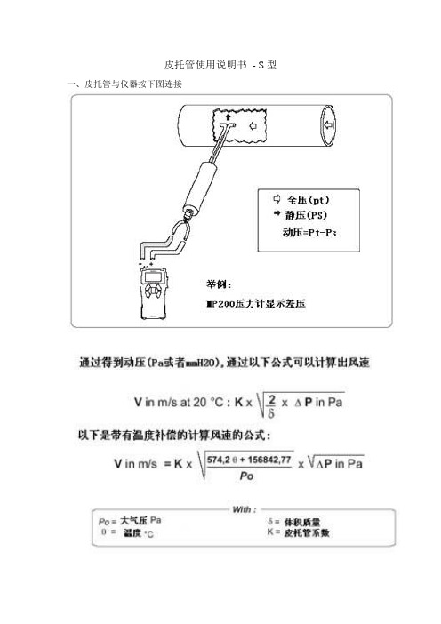
皮托管使用说明书- S型一、皮托管与仪器按下图连接二、主要技术参数:1. L型皮托管系数0.99-1.01之间,S型皮托管数0.81-0.86之间。
2. 测量空气流速不超过40 m/s,测量水流速度不超过25 m/s。
3. Φ8管最长1500 mm,Φ10管最长2000 mm,(公司备有各种规格皮托管)三、主要用途:在科研、生产、教学、环境保护以及隧道、矿井通风、能源管理部门,常用皮托管测量通风管道、工业管道、炉窑烟道内的气流速度,经过换算来确定流量,也可测量管道内的水流速度。
用皮托管测速和确定流量,有可靠的理论根据,使用方便、准确,是一种经典的广泛的测量方法。
此外,它还可用来测量流体的压力。
四、结构:1. L型皮托管用两根不同直经不锈钢管子同心套接而成,内管通直端尾接头是全压管,外管通侧接头是静压管。
指向杆与测杆头部方向一致,使用时可确定方向,使测头对准来流方向。
2. S型皮托管由二支同经管背向制成,迎风方为全压端,背风方为静压端。
五、使用方法:要正确选择测量点断面,确保测点在气流流动平稳的直管段。
为此,测量断面离来流方向的弯头、阀门、变径异形管等局部构件要大于4倍管道直径。
离下游方向的局部弯头、变径结构应大于2倍管道直径。
皮托管的直径规格选择原则是与被测管道直径比,不大于0.02。
以免产生干扰,使误差增大。
测量时不要让皮托管靠近管壁。
测量时应当将全压孔对准气流方向,以指向杆指示。
测量点插入孔处应避免漏风,防止该断面上气流干扰。
按管道测量技术规范,应合理选择测量断面的测点。
皮托管只能测得管道断面上某一点的流速,但计算流量时要用平均流速,由于断面流量分布不均匀,因此该断面上应多测几点,以求取平均值。
测点按烟道(管道)测量法规定,按“对数一线性”法划分,也可按常用的等分面积来划分。
S型皮托管静压接头处敲有标记号码,并在鉴定单上注明皮托管系数。
鉴定单应长期保存,以供计算。
六、保养使用中可能造成管子弯曲。
伊莱克斯ILG S型手动操纵气动执行器- 使用说明书

1/2Figure 1Figure 2Figure 31. PrefaceThe ILG/S gearbox is a sandwich manual override quarter turn gearbox for spring return pneumatic actuators . It is intended to be used for the manual operation of valves (e.g. butterfly valves) in pipelines.This manual is valid only for the standard ILG/S gearboxes. For special versions, quantities and model can differ.1.2 Handling and safety precautionsBe sure to read and understand this manual before installation and use of our standard ILG/S-gearbox.Storage: The gearboxes need to be stored in a safe way to avoid accidents. Avoid storage in areas subjected to high temperature extremes and/or areas subjected to high humidity and dust.Handling: Never drop the gearbox or expose it to strong impact.Correct use: Prior to installation, be sure the gearbox will NOT be overloaded during normal use. For this, check that the valve size and needed opening torque do not exceed the values given for the gearbox. For the maximum allowable torque on the gearbox, see table. InterApp is not responsible for any damage caused by incorrect use of the gearbox.Installation and operating: Not observing the rules as stated in this manual, can lead to damage and/ or personal injuries. The qualified personnel must be fully aware of the instructions as described in this manual. Only when the instructions are observed, correct operation of the gearboxes can be guaranteed.Disposal: Never put a gearbox at a general disposal unit. The gearbox has to be offered to a disposal depot for recycling. The iron parts can be used for recycling . The seals are of nitrile and can be used for plastic recycling.The grease may not be discharged to sewer- or surface water. It has to be disposed according to local regulations for incineration.2. Installation1 The gearbox is standard delivered in closed position.2 It is recommended to mount a handwheel on the input shaft prior to assembling the gearbox to the valve.3 Check if the bolt circle of the flanges (of gearbox and valve) coincides. Also check if the valve shaft and the bore of the coupling match.4 Make sure the valve is in the fully closed position. If not, close the valve before continuing.5 Put the gearbox in fully opened (!) position by turning the handwheel counterclockwise.6 In case of use of stud bolts for fixing the gearbox to the valve, it is recommended to screw them into the bottom flange of the gearbox prior to mounting the gearbox on top of the valve.7 The use of a gasket between the flange of the valve and gearbox is recommended.8 Put the drive shaft (see figure 1) into the gearbox. The size and shape of the connections can differ from the example in figure 1.9 Put the gearbox on top of the valve. Make sure the drive shaft is in the most left turned position (seen from the bottom side). See figure 2.10 The gearbox is mounted perpendicular to the valve (see figure 3).11Fix the gearbox to the valve with nut and ring. In case of use of bolts, for the maximum screw depth, see table below.1.1 Technical dataThe ILG/S gearboxes are of different types and sizes.Under normal conditions, the gearbox is maintenance free. The gearbox is greased and sealed for life. The maximum allowable input and output torques are listed in the following table.The gearboxes can be used at ambient temperatures from –20 to +85°C. Our standard gearbox reaches IP65 (dust- and waterspray proof). Cleaning can be done with a waterhose, but not a high pressure waterjet. For more specified information, you can contact our salesdepartement.12 The (spring-return) actuator can be mounted on top.13 The assembly is ready for adjustment (see next chapter).14 Before operating, be sure the gearbox is in opened position.2/2INSTALL-ILGS_1138© 2009 InterApp AG, all rights reserved InterApp AG Grundstrasse 24CH-6343 RotkreuzPhone +41 (0) 41 7982233Fax +41 (0) 41 7982234****************.netInterApp GermanyAVK Mittelmann Armaturen Schillerstrasse 50D-42489 WülfrathPhone +49 (0) 2058 901 01Fax +49 (0) 2058 901 110**********************InterApp Austria Kolpingstrasse 19A-1230 WienPhone +43 (0) 1 6162371-0Fax +43 (0) 1 6162371-99****************.net InterApp Italy Via Gramsci 29I-20016 Pero (MI)Phone +39 02 339371Fax +39 02 33937200****************.net InterApp VálvulasCalderón de la Barca 12E-28860 Paracuellos de Jarama Phone +34 (0) 91 6584360Fax +34 (0) 91 6581430****************.netAVK VálvulasPoligono Industrial Francoli, parcela 27E-46006 Tarragona Phone +34 977 543 008Fax +34 977 541 622*******************InterApp Singapore11, Changi North Street 1, #03-11Singapore 498823Phone +65 62141048Fax +65 62140481****************.netFigure 4enThe technical data are noncommittal and do not assure you of any properties. Please refer to our general sales conditions. Modifications without notice.3. Adjustment of the stops crewsThe gearbox is already mounted on top of the valve (see installation).1 With the valve in fully closed position turn handwheel counterclockwise toput the gearbox in opened (!) position. This may not affect the position of the valve (remains fully closed).2 Mount the (spring-return) actuator.3 Turn the handwheel clockwise to put the gearbox in fully closed position.When the full closed position can not be achieved, loosen the stops crew-close (see figure 4). Continue turning the handwheel until the valve is fully closed.4 Turn the screw back into the gearbox until blocked (handtight). Secure thestops crew–close with the counternut.5 Put the gearbox into the fully opened position by turning the handwheelcounter-clockwise.6 Use the actuator to put the valve in fully opened position. When the fully openposition can not be achieved, loosen the stops crew-open (see figure 4). Continue turning the handwheel counterclockwise, until the valve can be fully opened.7 Turn the stop-screw back into the gearbox until blocked (handtight). Securethe stops crew–open with the counternut.8 Depressurice the actuator.9 Close the valve completely, turning the handwheel clockwise.10 Put the gearbox into the fully opened position by turning the handwheelcounterclockwise.11 Adjustment completed. The gearbox is now ready for automatic operation.4. OperatingWith the gearbox correct installed, under normal circumstances the valve is operated by an actuator. The ILG/S gearbox allows manual operation (closing) of the valve in case of malfunction in the automatic actuator system.1 The gearbox is operated by handwheel.2 The valve is closed by turning the handwheel clockwise.3 Stop turning when the required valve position is achieved. The number ofrotations of the handwheel needed turn the valve from fully open to fully closed is stated in table below.4 When the valve can not be totally closed, first detect and solve the cause offailure.5 In case of malfunction of the gearbox, this one has to be replaced. Return thegearbox to your supplier for repair.6 When you do the repair in house, all replacement parts must be obtainedfrom the manufacturer to assure proper operation of the gearbox.7 The gearbox is self-braking. Therefore no fixation needs to be installed.8 When the malfunction is repaired, turn the handwheel until blocked.9The system is ready for use.。
S型全热产品说明书

型号
L
670 670 735 735
L1 W
65 65 75 75 55 0 55 0 63 0 63 0 85 0 85 0
W1 H
60 60 60 60 80 80 200 200 250 250
H1
100 100 125 125
D
E
F
D
G
19 19 19 19
W
W1
M
N
308 590 597 291 590 597 3 92 6 5 5 6 7 7 3 40 6 5 5 6 7 7
QFA-D1000S QFA-D1000S-Y 静压-风量性能曲线
600 500 400
高档
600 500 400 300
低档 低档
高档
300 200 100 0 200 400 600 800 1000 1200 1400 1600 1800 2000
QFA-D1500S QFA-D1500S-Y 静压-风量性能曲线
安装实例
备注:1 .必须安 装2个 室 外 风道(室内新 风 管 道 和排风管道) , 以 防 止冷凝; (材 料 : 保温材料, 厚 度 :2 5 m m) 2 .检 修 空 间必须预留检 查 盖 下 方300以上。
Q FA-D 150 S-Y
线控型(普通型不表示) 薄型 风量150m³/ h 吊顶式安装 新风设备 全热型
保修卡 姓 名 电 话 年 月 日
单位或地址 保修期限
购买日期
1、 本 产 品 整 机 维 修 一 年,在 正 常 使 用 状 况 下 免 费 维 修 。 2、 保 修 期 的 起 始 日 期 以 产 品 发 票 日 期 为 准 。 3、 维 修 时 请 出 示 发 票 。 4、 在 保 修 期 间 , 若 有 下 列 情 况 恕 不 免 费 维 修 。 •由 于 没 有 按 说 明 书 上 要 求 使 用 而 造 成 故 障 的 。 •由 于 自 行 修 理 改 装 以 致 损 坏 的 。 •由 于 不 可 抗 力 因 素 所 造 成 的 故 障 或 损 坏 的 。 •由 于 非 正 常 使 用 ( 如 长 时 间 使 用 于 环 境 恶 劣 的 场 所 或 车 辆 、 船舶上搭载)所造成之故障或损坏的。 •由 于 人 为 敲 击 、 摔 、 撞 、 切 、 割 等 损 坏 的 。 5、 超 过 保 修 期 或 不 属 于 免 费 保 修 的 产 品 , 本 公 司 的 特 约 维 修 点 仍竭诚为您服务。
s型双吸离心泵技术说明
s型双吸离心泵技术说明大家好,今天我们来聊聊这个听上去有点儿高大上的东西——S型双吸离心泵。
你可能想,这玩意儿到底是什么,跟我有什么关系?别急,慢慢来,我给你细细说。
想象一下,一个威武的泵,像是工业界的“阿甘正传”,不管走到哪里,总能给人带来水的欢乐。
S型双吸离心泵的名字就很形象。
就像S型的弯道一样,它的设计灵巧得很。
泵的内部结构可以说是个小宇宙。
它有两个进水口,像双胞胎一样,水一来就被吸得“哗哗”作响。
这样一来,流量就翻倍了,真是让人眼前一亮。
就好比你跟朋友一起吃饭,大家一口气点了很多好吃的,结果桌子上全是美味,吃得不亦乐乎。
然后,咱们来聊聊这泵的性能。
它能处理的水量可不是开玩笑的,尤其在一些大工程、矿山或者工业生产中,根本离不开它。
有人说,它就像是现代工业的“水车”,不管是给工厂供水还是排水,通通不在话下。
真是一个多面手。
运转起来可安静了,简直比我家那只猫还温柔,没什么噪音,偶尔发出轻轻的“咕咕”声,简直像在打呼噜,听了让人心安。
至于材质,哎呀,那可是讲究得很。
一般都是用铸铁、铸钢这些坚固耐用的材料,能抗得住各种恶劣环境。
这就好比你的运动鞋,不但要轻便,还得耐磨,才能陪你跑得更远。
这样一来,S型双吸离心泵可就能“百战百胜”了,能在恶劣的环境中“顽强拼搏”,真是没谁了。
说到维护,别担心。
这泵的设计也很人性化,日常维护可简单多了。
只要定期检查一下,清理清理就行。
就像你偶尔给家里的电器做个“体检”,这样一来,泵就能一直保持最佳状态,持续为你“供水”。
这可是长久之计,像老祖宗说的“细水长流”,一点也不假。
别小看它的应用场景。
S型双吸离心泵可不仅仅是工厂里待着的“书呆子”。
在城市的供水系统、消防系统中,处处都能看到它的身影。
想想那些大楼高耸入云,如果没有它,恐怕每天的用水就成了大问题。
就像“万事俱备,只欠东风”,缺了它,水源问题可真难搞。
当然了,使用这种泵的时候,也有一些小窍门。
比如说,启动时要注意水位,确保泵里有足够的水,否则就会“干烧”,那可就得不偿失。
乐维顿制造公司S-型墙内扬声器产品数据说明书
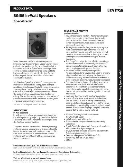
Leviton Manufacturing Co., Inc. Global Headquarters201 N. Service Rd. Melville, NY 11747-3138 Tech Line: 1-800-824-3005 Fax: 1-800-832-9538Leviton Manufacturing Co., Inc. Energy Management, Controls and Automation.4330 Michoud Blvd., New Orleans, LA, 70129 Tel: 1-504-736-9810 Fax: 1-504-253-2954Visit our Website at: /emca©2016 Leviton Manufacturing Co., Inc. All rights reserved. Subject to change without notice.SGI65 In-Wall SpeakersSpec-Grade ®S G I 65 I n -W a l l S p e a k e r s P o w e r e d b y S p e c -G r a d e ®When the specs call for quality sound, rely onLeviton’s award-winning* Spec-Grade Sound™ indoor and outdoor speaker line for exceptional technical innovation and value. Spec-Grade Sound speakers deliver features and performance comparable to higher-end brands, at a price that’s right for the entire range of the residential installation and construction business.All of Leviton Spec-Grade Sound™ indoor speakers incorporate exceptionally strong, light and rigidAeroNylon tweeters and Kevlar®-composite woofers for exceptional clarity, detail and impact, along with built-in AutoSurge™ protection to help protect the speakers from possible damage due to overdriving. The outdoor/utility speaker is constructed of weather resistant materials inside and out for years of use in challenging environments.*Electronic House Magazine “Product of the Year”APPLICATIONS In-Wall SpeakersIn-wall speakers offer a no-compromise choice for installed systems by projecting sound directly into a listening area from a horizontal location just like a shelf or floor speaker system.They are a perfect solution for: 1. Primary listening systems: musical applications where sound quality is most important and wall locations do not conflict with room aesthetics. 2. Installed home theater systems: as front left and right speakers, and as surround speakers.FEATURES AND BENEFITS (In-Wall Models)• Kevlar® composite woofer – Woofer construction combines exceptional rigidity and lightness to provide the perfect linear movement needed to reproduce dynamic, tight bass and incisive midrange frequencies• AeroNylon tweeter diaphragm – Aerospace-grade nylon tweeter diaphragm combines very lowmass and high tensile strength to provide crystal-clear treble response and exceptionally accurate tracking of even the most challenging musical transients• AutoSurge™ circuit protection – Built-in AutoSurge protection responds to potentially destructive power peaks automatically and resets after the event, helping prevent speaker damage • Advanced phase/time alignment guide –A precise phase/time waveguide is used to properly align sound without mis-aligning the tweeters – a problem with many adjustable in-wall speakers – in order to provide extremely accurate stereo imaging • Precision dividing network – The dividing network (or crossover) used in all Spec-Grade Sound speakers is made of high-spec components to ensure total audio signal electronic integrity up to the last microsecond before the signal is converted into sound• Inert mounting frame with “dogleg” installation • points – To eliminate any transmitted vibrations that could color in-wall or ceiling sound quality, Spec-Grade Sound speakers rely on a baffle-frame assembly incorporating higher-density plastics and a series of adjustable “doglegs” to rigidly clamp the speaker to the wall or ceiling material• 6.5- Inch Two-Way In-Wall Loudspeaker (Cat. No. SGI65-00W)• Includes paintable white grille• 6.5-inch Kevlar composite cone low-frequency transducer• .5-inch AeroNylon dome high-frequency transducer with phase/time alignment guide• 2-way balanced precision crossover network with AutoSurge circuit protection• Frequency Response: 50-20kHz +/- 3dB • Sensitivity: 88.0 dB SPL @ 1Watt/• 1 MeterSAT-10092Leviton Manufacturing Co., Inc. Global Headquarters201 N. Service Rd. Melville, NY 11747-3138 Tech Line: 1-800-824-3005 Fax: 1-800-832-9538Leviton Manufacturing Co., Inc. Energy Management, Controls and Automation.4330 Michoud Blvd., New Orleans, LA, 70129 Tel: 1-504-736-9810 Fax: 1-504-253-2954Visit our Website at: /emca©2016 Leviton Manufacturing Co., Inc. All rights reserved. Subject to change without notice.65 PRODUCT DATA• Power Handling: 120W peak/60W RMS • Impedance: Nominal 8 Ohms/• Minimum 6 Ohms• Physical Dimensions and Weight:• Height: 12.31 in/312.8 mm • Width: 9.02 in/229 mm • Depth: 3.20 in/81.28 mm • Weight: 7.3 lbsPRE-CONSTRUCTION BRACKET KIT Cat. No.: PCI65INSTALLATION INSTRUCTIONSCAUTION: NOTE THAT THIS MANUAL IS WRITTEN WITH THE ASSUMPTION THAT THE INSTALLER POSSESSES SKILL IN THE PROPER USE OF HAND AND POWER TOOLS, AND IS FAMILIAR WITH THE ENVIRONMENT BEHIND THE SURFACE OF THE WALL OR CEILING WHERE THE SPEAKERS WILL BE INSTALLED. TO INSTALL:1. S elect speaker mounting location. Route speaker cable from source to this location. Note: We recommend the use of 16/2 (minimum) class 3 speaker wires.2. A ttach wings to back plate of Pre-Construction Bracket (refer to Figure 1A). Only two wings are required for each back plate. Select the mounting arrangement that best suites your specific application. Note: The wings are designed to be shortened as required.3. A ttach the Pre-Construction Bracket in the desired location to the underside of framing members so that after drywall installation, the bracket and the wings are sandwiched between the drywall and the framing member (ensure “FRONT” is facing into the room) (referto Figure 1A). If the mounting area is too congested to use both mounting wings you can drive screws through 4. L 5. A。
- 1、下载文档前请自行甄别文档内容的完整性,平台不提供额外的编辑、内容补充、找答案等附加服务。
- 2、"仅部分预览"的文档,不可在线预览部分如存在完整性等问题,可反馈申请退款(可完整预览的文档不适用该条件!)。
- 3、如文档侵犯您的权益,请联系客服反馈,我们会尽快为您处理(人工客服工作时间:9:00-18:30)。
二、产品简介
1、起动风速低,风能利用率高;体积小,外型美观、运行振动轻。
2、采用人性化设计,方便设备的安装、维护和检修。
3、风轮叶片采用新工艺经精密注射成型,配以优化的气动外形设计和结构
设计,风能利用系数高,增加了年发电量。
4、发电机采用专利技术的永磁转子交流发电机,配以特殊的定子设计,有
效地降低发电机的阻转矩,同时使风轮与发电机具有更为良好的匹配特
性,机组运行的可靠性。
5、技术参数
三、塔架及附设制作
1、本公司该型号风力发电机的法兰底座装配在铁管外径为48毫米、壁厚为4.5
毫米的圆筒型塔架上。
2、铁管是圆筒型塔架的主体,其长度可根据用户装配风力发电机地点的风况和
地理环境来确定。
3、塔架的附件包括(1)塔架的上端制作,(2)拉线组,(3)紧线器,(4)地锚,
(5)线钩,(6)基墩,(7)防锈、防腐、表面涂层材料等组成。
图一地锚、土墩、拉索的制作
4、塔架的上端的制作样式及尺寸见图二,其要求是焊接牢固、与圆筒塔架的焊
接处不能漏水、接地连接板要焊接在距地面20公分处(要明显看得见),它将与防雷接地装置连接。
与接地极连
图二风力发电机法兰对接在塔架上端图
5、防雷接地装置的布置可参照国标、欧盟标、美标进行。
也可以按照本手册提
供的表1作参照进行布置。
6、塔架的主体和附件也可以根据用户的要求另行选配。
四、风力发电机安装步骤
·风力发电机的组装和安装应在无风无雨的天气下进行。
1、电流传输绝缘导线:传输线铺设在支架钢管内,其上端由法兰连接头内孔引
出,下端由距地面30公分的开口引出,从引出处到地表下60公分处的传输线要用外径为17~21豪米的铁管保护。
传输线的地下路径可用铁管或塑料组成并管连接到控制器所在地。
2、风力发电机的装配顺序可按(图三)的步骤进行。
2-1、将钢管支架置于现场地面,法兰连接头端垫高至1.3米左右。
2-2、将风力发电机法兰座移向法兰连接头,塔架引线终端(接控制器的一端)导线削去约10mm长的一段绝缘层,并将三根露出的导线(短路)拧接在
一起。
2-3、将法兰螺栓(9)装上平垫圈(10)后,使其头在上、丝在下插入风力发电机法兰座对应的孔内,再将其连接到塔架的法兰上,平垫圈(10)、用弹性垫圈(11)套入螺栓丝,最后用扳手把螺帽(12)拧紧在法兰螺栓丝上。
同理将其余螺栓、平垫、弹垫、螺帽等入座对应的其他孔内。
拧紧4个螺帽,拧紧力度可参照表2进行。
3、装风轮片:风轮片(6)的双孔装在风轮毂(5)双孔凹槽内,配合以平稳、
服贴、双孔全部对齐为准,否则,将风轮片翻一面再装。
不锈钢法兰螺钉(13)从正面穿入孔内,拧入尼龙抗松螺帽(14)(注意:抗松螺帽只能紧而不能松,属一次性螺帽,否则,失去抗松作用)。
其余风轮片与此雷同。
拧紧力度参照表2进行。
4、先将抗松螺母(7)大头端放进风轮毂中间六角孔内,一起置于风力发电机体
的螺纹轴内,左手按住螺母,右手顺时转动风轮,螺母推进,再用随机附带的加长内六角板手配合右旋风轮片,锁紧螺母(注:螺母准进不准退)。
锁紧
力度可参照表2螺纹扭紧力度表。
5、装整流罩:整流罩(8)与风轮毂(5)的配合属扣配,整流罩三个缺口对位
于风轮片,用手掌拍击整流罩锥体,三个方向的扣齿,以都扣进风轮毂外缘止口内为准。
6、吊装风力发电机及塔架应在有熟练吊装工的情况下,并保证人身绝对安全。
塔架的设立应按永久性建筑的有关要求施行。
7、风力发电机塔架装设好,防雷接地设施到位,在不松开电流传输线短路头的
情况下,用500V摇表测量传输线与大地的绝缘电阻值(防雷接地线可代表大地)应不小于5MΏ。
如小于此值,则可能会导致传输线绝缘层有压伤、割伤,或接头未包扎好受潮湿碰触塔架,应速处理。
图三风轮机分解图
五、传输线与受电器的连接
·首次试运行不要在暴风暴雨天气下进行,最好是在和风或强风(风速5~13米/秒)状态下试机。
1、将蓄电池的正极和负极准确地连接到控制器(风光发电专用控制器)的接线
柱(孔)的正极和负极上。
太阳能电池接线柱(孔)上。
2、负载线路经熔断器、开关和插头连接在控制器背面的插座上。
3、风力发电机三根电流传输线连接在控制器背面的三个接线柱(孔)上。
接线
详细参照:风力发电专用控制器,风光互补路灯控制器,风光发电专用控制逆变器等相关手册。
4、蓄电池一般选用铅酸蓄电池,100-300W风力发电机可选100-200AH的蓄电池,
300-600W风力发电机可选用200-400AH的蓄电池,充电电压的上下限都由逆变器控制。
风力发电机采用浮充制对蓄电池充电,至于浮充电电流的大小,与电池的新旧程度、放电深度、维护好坏都有关系。
5、控制器要放置于干燥、通风良好的地方,潮气和尘埃不得入内,逆变器外壳
要保持接地,距蓄电池要1.5米以上,以免酸气污染损坏逆变器。
6、蓄电池要按装在干燥、夏天阴凉通风、冬天保暖避风的地方,以维护其充放
电容量和延长蓄电池使用寿命。
风轮机、太阳能板与控制器、蓄电池、用电器连接图
六、运行中的保养与注意事项
1、风力发电机工作的自然环境是很恶劣的,经常视查、耳听、检查杆塔是否随风摇摆、拉线是否松动(可以采用望远镜视查的方法)。
2、特大风暴前后应即时检查,发现风力发电机有问题时应徐徐放倒塔架进行检修。
路灯风力发电机应由外线电工上杆检修,但必须先将风力发电机短路并有安全保护措施。
3、免维护型蓄电池要保持外表清洁。
4、如发生故障,请勿自行拆卸设备,及时联系公司销售部。
七、装箱清单
太阳能路灯地埋箱是随着太阳能路灯的发展和应用而开发的产品。
主要用于装备蓄电池。
地埋箱材质为:聚丙烯,PP的一种,它是针对太阳能灯工程在实际施工过程中遇到的种种特殊问题而精心设计的,从根本上解决了太阳能路灯地埋式蓄电池在工作过程中的防水、散热、排气等相互矛盾的问题。
太阳能地埋箱具备以下产品特点:
1、地埋箱通过地下密封处理,解决了防水问题。
2、地埋箱通过穿线管延伸到灯杆底部穿线的同时,解决了透气的问题。
3、地埋箱通过独有的栅栏式加强筋设计,有效的实现了蓄电池在内部环境下的散热保温问题。
4、采用优质材料一次性注压而成,且具有抗震、防腐蚀、耐酸碱等特点,蓄电池地埋箱的承压强度高。
5、地埋箱通过埋在地下,并于灯的基础相连的特性,有效地起到了防盗的作用。
整套产品包含:箱体、不锈钢导丝管、不锈钢螺丝、垫片、硅胶条。
太阳能地埋箱的使用方法有两种:
第一种简易安装:
1、将蓄电池接好导线,将接线柱封胶;
2、将蓄电池放入蓄电池地埋箱中,将导线从地埋箱的穿线孔穿出,将地埋箱用配套的紧固件收紧;
3、最后将箱体直接埋在地下。
第二种针对防盗的安装方法:
1、先将蓄电池接好导线,将接线柱封胶;
2、将蓄电池放入蓄电池地埋箱中,将导线从地埋箱的穿线孔穿出,将地埋箱用配套的紧固件收紧;
3、最后将箱体放入事先砌好的水泥池中,将水泥池的盖子盖好。
11。