伺服阀使用说明书
EWS 3 3 通道伺服阀操作手册说明书

TetraTec Instruments GmbHGewerbestrasse 871144 SteinenbronnDeutschlandEmail:****************Tel.: 07157/5387-0Fax: 07157/5387-10 OPERATION MANUALEWS3/3 Way Servo Valve*** VERSION 2.0 ***Stand: 01.10.2016Operating ManualEWSExtent of supply• Servo valve cartridge EWS 3/x• SVE1/x• Cable between cartridge and controller• Installation and operating manualGeneral DescriptionThe servo-valves EWS 3/4 and EWS 3/6 are direct driven 3/3-way-valves with patented rotary slide principle and electronic closed loop slide position control. They are designed as cartridge to provide space- and cost-saving solutions especially in serial products. The corresponding electronic controller is available in 3 different versions.Important: The valve controllers are adjusted to the corresponding cartridges. A correct function needs a cartridge and a controller with identical serial numbers.PLEASE READ THIS OPERATING MANUAL COMPLETLY BEFOREINSTALLATIONPLEASE PAY ATTENTION TO THE FOLLOWING IN ANY CASE1.) Use only 5 µm – fine filtered, oil-free compressed air for flow measurements,pressure controls or leak tests.2.) Before connection of pneumatic pipes:Clean fittings, hoses etc. !(leave no cuttings, dust, corrosion products, sealing particles etc.)3.) Use only flat sealing fittings with cylindrical G1/4“ threads.If flat sealings are not possible or if it’s very difficult to get them tight, make thesealing with surface or thread adhesives.Do never seal the inlet pipes to valves, controls or flow meterswith teflon-band, hemp etc.4.) Make sure that the connected load is clean!(no cuttings, dust, corrosion products, sealing particles etc.)Seite 2 EWS_man_e.docOperating ManualEWS Installation Hints:The fitting blocks, fittings and tubes must be absolutely clean, no cuttings, dust, rust, sealing particles, etc.Fitting blocks from aluminium have to be anodised.Use only fittings with non-tapered cylindrical threads and axial flat sealing; neveruse liquid sealing (e.g. Loctite), teflon-band, hemp etc.Technical data, part numbers and accessoryElectrical dataPower supply SVE1/x 24 VDC +/- 10%, stabilized, max. 0,8 A Input specified value ../B +/- 10 V vs. 100 kΩ../U 0...10 V vs. 100 kΩ../I 0...20 mA vs. 500 ΩHysteresis approx. 1% FSLinearity approx. 1% FS related to slide position Frequency limit (-3dB, -90°) a t ± 100% spec. value: approx. 70 Hzat ± 50% spec. value: approx. 110 Hz Switching time 0 ↔ 100%: approx. 5 ms± 100%: approx. 7msPneumatic dataMaximum flow rate EWS 3/4 EWS 3/66 bar 0 bar 700 Nl/min 1100 Nl/min6 bar 5 bar 450 Nl/min 690 Nl/minMedium clean air, 5 µm filtered, not oiledSupply pressure vacuum to 10 barLeakage < 1% of maximum flow rateGeneral conditionsTemperature range 0 to 50 °CRel. humidity of air max. 90%Direction of assembling anyWeight cartridge approx. 0,14 kg without cableEWS_man_e.doc Seite 3Operating ManualEWSSeite 4EWS_man_e.docController SVE1/x:Controller as SMD-PCB fitted into a metallic 25-pin SUB-D-plug with the dimensions 56 x 54 x 15 mm³; supply voltage 24 VDC; cable to the valve cartridge pluggable at the valves end, cable length standard 0,5 m, max. 2 m.EWS Cartridge Housing:Pneumatic InstallationThere are no restrictions for pneumatic installation.The typical modes of installation to control a pneumatic load are the modes I and II (see table below); the only difference is the relation between directions of flow and specified value. Low specified values connect always ports 1 and 2, high specified values ports 2 and 3. The modes III and IV allow flow control of two pneumatic loads with only one servo valve.The inner diameters of connected fittings and tubes should correspond to the nominal size of the valves, at least 4 mm for EWS 3/4 and 6 mm for EWS 3/6.The length of the leads should be as short as possible, between valve-outlet and load normally not more than 2 m.Option .../B -10 V ⋅⋅⋅ 0 V ⋅⋅⋅ +10 V Option .../U 0 V ⋅⋅⋅ +5 V ⋅⋅⋅ +10 V Option .../I 0 mA ⋅⋅⋅ 10 mA ⋅⋅⋅ 20 mA Port1 ⋅⋅⋅2 ⋅⋅⋅ 3I P A R II R A P III A P B IVA R BOperating ManualEWSEWS_man_e.docSeite 5Electrical InstallationController SVE1/xPinFunction7 power supply: +24 VDC 13 power supply: GND 14 input specified value -floating GND, max. voltage vs. power supply GND +/- 30 V15input specified value + vs. pin 14: SVE1/B: +/- 10 V SVE1/U: 0...10 V SVE1/I: 0...20 mA 25 input Inhibit: 24 VDC vs. pin 13 (disables valve action) 6, 8 internal reference potentialnever connect to other GNDs! 1 test point motor voltage +/- 10 V vs. pin 6 24test point slide position +/- 1 V vs. pin 6Dimensions of EWS Cartridge HousingOperating ManualEWSSeite 6EWS_man_e.docDimensions of EWS Counter HousingsDimensions of EWS Valve Housing VG6Fitting block with G1/4”-bores, material: aluminium, black anodisedThe dimensions of the EWS-cartridge and for corresponding fitting blocks are given in the above sketches. Additionally three possibilities for the design of the pneumatic connection are shown; it is very important, that the minimal flow areas are not smaller than the nominal size of the valves: for EWS 3/6 at least approx. 30 mm², for EWS 3/4 at least approx. 15 mm².There must be recesses (ø26 in the sketch) in the fitting block to prevent damages of the O-rings while fitting the cartridge into the block, the inner edges must be chamfered. Because of the valves leakage the fitting block must be exhausted at both axial ends. Axial torques must be prevented from the fitted cartridge. When assembling ordisassembling cartridge and block the cartridge has to be moved exactly axial to prevent damages at cartridge, O-rings or fitting block.。
DDV说明书
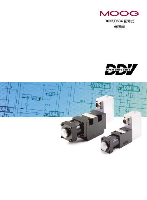
MOOGMOOG( 穆格 )DDV 伺服阀MOOG( 穆格 )D633 、 D634 系列伺服阀是 MOOG 公司最新研制成功的新型电液伺服阀,目前已由 MOOG GmbH( 德国 ) 公司进行批量生产。
它是一种直接驱动式伺服阀,简称DDV(Direct Drive Servo Valve 的缩写 ),油口与安装尺寸D633 按 NG6(Cetop 3),D634 按NG10(Cetop 5) ,用集成电路实现阀芯位置的闭环控制,阀芯的驱动装置是永磁直线力马达。
对中弹簧使阀芯保持在中位,直线力马达克服弹簧的对中力使阀芯在两个方向都可偏离中位,平衡在一个新的位置,这样就解决了比例电磁线圈只能在一个方向产生力的不足之处。
阀芯位置闭环控制电子线路与脉宽调制(PWM )驱动电子线路固化为一块集成块,用特殊的连接技术固定在伺服阀内,因此 D633、D634 系列伺服阀无需配套电子装置就能对其进行控制。
D633、 D634 系列伺服阀是MOOG 公司对其经久考验,盛名于世的双喷嘴力反馈两级伺服阀的发展与补充,和传统的MOOG30 、31、 32、 34、 35、E760 等系列伺服阀相比,其最大的区别在于D633、D634 系列伺服阀从结构上取消了喷嘴一挡板前置级、用大功率的直线力马达替代了小功率的力矩马达,用先进的集成块与微型位置传感器替代了工艺复杂的机械反馈装置—力反馈杆与弹簧管,从而简化了结构,提高了可靠性,大大地降低了制造成本,却保持了带喷挡前置级的两级伺服阀的基本性能与技术指标。
MOOG DDV 伺服阀的特点1.在位置、速度、压力以及力电液伺服系统中可用二位二通、三位三通或三位四通的方式进行工作。
2.安装形式与尺寸符合DIN24340 和 cetop3 与 6。
3.无液压前置级。
4.停电、电缆损坏、或者紧急停车情况下伺服阀均能自行回中,无需外力推动。
5.动态性能指标与供油压无关。
6.防水性为IP65(DIN40050) 级。
维克斯SM4-30伺服阀说明书
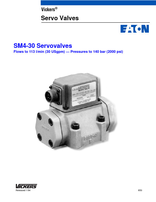
Flows to 113 l/min (30 USgpm) — Pressures to 140 bar (2000 psi)653Released 1/94SM4-30 ServovalvesVickers ®Servo ValvesIntroductionVickers SM4-30 servovalves can provide system closed loop control with exact positional accuracy, repeatable velocity profiles, and predictable force or torque regulation.Typical applications include plastic injection molding and blow molding systems, test and simulation equipment, die casting machines, hydraulic press brakes, animation and entertainment equipment, oil exploration vehicles, and lumber machinery.This model of the high performanceSM4 series offers a wide range of rated flows from 57 to 113 l/min (15 to 30 USgpm) at n p of 70 bar (1000 psi).The SM4 is a two-stage, modular design, flow control valve which can be manifold or subplate mounted. Thesymmetrical, dual coil, quad air gaptorque motor is integrally mounted to thefirst stage nozzle flapper pilot valve withtwo studs. An integral 35 micronabsolute filter protects againstcontamination of the pilot stage. Thesecond stage utilizes a four-way slidingspool and sleeve arrangement with amechanical null adjust. Spool position isfed back to the first stage by means of acantilever spring.An SM4 servovalve, when used with ahydraulic cylinder, position transducer,and appropriate electronics, can provideinfinite cylinder position control to within0,025 mm (0.001 in) or better, dependingon component selection, length of stroke,and load characteristics.When applied with servo hydraulicmotors, tachometers, and appropriateelectronics, the SM4-30 can provideinfinite proportional flow control forreal-time velocity/acceleration profiles.Thes profiles can be closed loop errorcorrected to within one-tenth of arevolution per minute. When used withpressure transducers or load cells,cylinders, and appropriate electronics inforce control applications, the SM4offers exact load pressure/force controland excellent system stability withpressure and load to ±1% full scale.The field-proven design of the SM4-30servovalves, combined with Vickersprecision manufacturing techniques,provides you with the optimum insystem control.Features and BenefitsD The wide range of SM4-30 flow capabilities allows selection of the valve size best suited for an application.D The cast aluminum alloy second stage valve body with internally cored flow passages means lighter weight with rugged durability.D The symmetrical, dual-coil, quad air gap, dry torque motor in Vickers servovalves, with its extremely fast response to input signals, can produce highly accurate control profiles.D Higher frequency response is available on request. This feature provides enhanced system bandwidth for critical performance requirements.D An integral 35 micron absolute filterprovides extra first stagecontamination protection.D The spool and sleeve are hardenedstainless steel to minimize wear anderosion. The O-ring mounted sleeveeliminates spool binding to ensuresmooth operation.D Customized spool lap and sleeveporting are available to provide thespecific flow control required forspecial applications.D The SM4’s symmetrical designprovides inherently dependablemetering of control flow with minimumnull shifts. The result is moreconsistent machine operation.D Viton* seals are standard.D The flexibility of a standardized portcircle and mounting pattern, withavailable adapter manifolds, makesVickers SM4-30 servovalves acost-effective choice for replacingexisting servovalves and enhancingsystem performance.D Flushing valves are available that cangreatly reduce initial systemcontamination levels prior to SM4installation.*Viton is a registered trademark of theDuPont Co.Vickers, Incorporated 1994 All Rights ReservedContentsOperating Data . . . . . . . . . . . . . . . . . . . . . . . . . . . . . . . . . . . . . . . . . . . . . . . . . . . . . . . . . . . . . . . . . . . . . . . . . . . . . . . . . . . . . . . . . . . . . . . . 3 . . . . . . . . . . . . . . . . . . . . . . . . . . . . . . . . . . . . . . . . . . . . . . . . . . . . . . . . . . . . . . . . . . . . . . . . . . . . . . . . . . . . . . . . . . . Performance Curves7 . . . . . . . . . . . . . . . . . . . . . . . . . . . . . . . . . . . . . . . . . . . . . . . . . . . . . . . . . . . . . . . . . . . . . . . . . . . . . . . . . . . . . . . . . . . . . . . . . Model Code10 . . . . . . . . . . . . . . . . . . . . . . . . . . . . . . . . . . . . . . . . . . . . . . . . . . . . . . . . . . . . . . . . . . . . . . . . . . . . . . . . . . . . . . . . Installation Dimensions11 . . . . . . . . . . . . . . . . . . . . . . . . . . . . . . . . . . . . . . . . . . . . . . . . . . . . . . . . . . . . . . . . . . . . . . . . . . . . . . . . . . SM4M(E) Mounting Subplates12 . . . . . . . . . . . . . . . . . . . . . . . . . . . . . . . . . . . . . . . . . . . . . . . . . . . . . . . . . . . . . . . . . . . . . . . . . . . . . . . . . . . . . . SM4A Adapter Manifolds15 SM4FV Flushing Valves17 . . . . . . . . . . . . . . . . . . . . . . . . . . . . . . . . . . . . . . . . . . . . . . . . . . . . . . . . . . . . . . . . . . . . . . . . . . . . . . . . . . . . . . .. . . . . . . . . . . . . . . . . . . . . . . . . . . . . . . . . . . . . . . . . . . . . . . . . . . . . . . . . . . . . . . . . . . . . . . . . . . . . . . . . . . . . . . . . . . . . . . . . . . . . Weights18 . . . . . . . . . . . . . . . . . . . . . . . . . . . . . . . . . . . . . . . . . . . . . . . . . . . . . . . . . . . . . . . . . . . . . . . . . . . . . . . . . . . . . . . . Additional Accessories18 Application Data19 . . . . . . . . . . . . . . . . . . . . . . . . . . . . . . . . . . . . . . . . . . . . . . . . . . . . . . . . . . . . . . . . . . . . . . . . . . . . . . . . . . . . . . . . . . . . . .1Cross Section of Typical SM4-30 ServovalveOperating DataFlow and LeakageAll data is typical, based on actual tests at 70 bar (1000 psi) ∆p, 30 cST (141 SUS), and 49°C (120°F).Model Series Maximum RatedFlow ±10%l/min (USgpm)Maximum TotalNull Leakagel/min (USgpm)Maximum Pilot Flowl/min (USgpm)SM4-30 (-20 design)113 (30)2,1 (0.55)1,0 (0.26)PerformanceMaximum Supply Pressurebar (psi)140 (2000)Minimum Supply Pressurebar (psi)14 (200)Proof Pressure% maximum supply pressure At Supply Port:150 At Return Port:100Burst Pressure, Return Port Open% maximum supply pressure250Maximum Operating Temperature°C (°F)135 (275)Hysteresis Around Null% of rated current≤3Symmetry Error% of rated current<10Linearity Error% of rated current<10Threshold% of rated current≤0.5Ruggedness Test ResultsVibration Test5 Hz to 2000 Hz along each axisNo damage to componentsShock TestUp to 150g along all axesNo damage to componentsEndurance TestTo ISO 6404No degradation in performance3% INPUT CURRENT 45Change in Rated FlowRated flows at valve pressure drops from 5 bar (70 psi) to 210 bar (3000 psi) for the four available spools.00P O W E R T R A N S M I S S I O N E F F I C I E N C Y – %10200.20.4Power Transmission EfficiencyMaximum power envelope expressed as a percentage with T port pressure equal to 0 bar.Power transferred to the load is optimum when valve pressure drop is one third of supply pressure. Load pressure drop should be limited to 2/3 of supply pressure so the flow gain of the servovalve remains high enough to maintain control of the load. Overall hydraulic efficiency must be considered when sizing system heat exchangers.RATIOLOAD PRESSURE DROP SUPPLY PRESSURE304050607080901000.60.8 1.05(70)VALVE PRESSURE DROP (P →A)+(B →T) – bar (psi)7(100)14(200)21(300)35(500)70(1000)140(2000)N O -L O A D F L O W R A T E4 (1)8 (2)11 (3)15 (4)19 (5)27 (7)30 (8)38 (10)57 (15)76 (20)95 (25)114 (30)135 (35)151 (40)190 (50)211 (55)228 (60)(30) 113(25) 95(20) 76(15) 57V A L V E R A T E D F L O W – l /m i n (U S g p m )Electrical Polarity forControl Flow Out of B PortSingle:A+,B –orC+,D –Series:A+,D –Connect B and CParallel:A+,C+B –,D –Connect A and C Connect B and DDifferential:A –,D –B+,C+Connect B and C BC –, current BA>CD BC+,current CD>BAA B C D +––+–+A B C D ServovalveServovalve6Coil ResistanceSelect coil resistance and connections for compatible interface to servoelectronics. Recommended coil rated current and resistance is shown in bold print.Nominal Resistance Rated Current mA Nominal Resistance Per Coil at 21°C (70°F)OhmsSingle, Parallel, orDifferential Connection Series Connection Standard coil rated current and resistance selection 806532.5Optional coil rated current and resistance selection805025Calculating Frequency Response at System PressureP S =System pressureP M =maximum supply pressure ofvalve: 140 bar (2000 psi) for SM4-30f PM =Frequency (at 90° phase angle) atmaximum supply pressure (P M )f PS =Frequency (at 90° phase angle) atsystem pressure (P S )1.Calculate the ratio of systempressure to maximum supply pressure:e the result of step 1 and thecurve below to estimatee the applicable frequencyresponse curve from the following pages to estimate f PM (the maximum supply pressure frequency response at 90° phase angle) for the desired valve rated flow.4.Multiply the values obtained in steps2 and 3. The result is f PS (system pressure frequency response at 90°phase angle).Frequency ResponseFrequency response is defined as the relationship of no-load control flow to input current with a sinusoidal current sweep at constant amplitude over a range of frequencies. It is expressed in frequency (Hz), amplitude ratio (dB),and phase angle (degrees).As shown in the sample curve (below left), standard comparison points for servovalve frequency response are those frequencies at which –3 dB amplitude ratio and 90° phase angle occur.Vickers SM4 torque motors are magnetically stabilized for reliable servovalve performance at operating pressures from 14 to 1400 bar (200 to 2000 psi).Example: An SM4-30 valve with a flow of 95 l/min (25 USgpm) is to be used at 110 bar (1600 psi).1.Calculate the ratio of systempressure to maximum supply pressure:e the result of step 1 and the curve below right to estimatee the frequency response curvefrom page 8 to estimate f PM .4.Multiply the values obtained in steps2 and 3. The result is f PS (system pressure frequency response at 90°phase angle).00.21.00.80.60.40.40.6 1.00.8P S(system pressure)P M (maximum supply pressure)fPSf PM0–5–10FREQUENCY – HzA M P L I T U D E R A T I O – d BP H A S E A N G L E – d e g r e e s12090–15–2010080706050403020101100.90.70.50.10.30.50.90.7P S P M f PS f PM P S P M +1600psi2000psi+0.8f PSf PM +0.92f PM +35Hzf PS +0.92 35Hz +32Hz7Performance CurvesSM4-3095 l/min (25 USgpm)113 l/min (30 USgpm)21020304050700–5–10A M P L I T U D E R A T I O – d BP H A S E L A G – d e g r e e s80–15–201009070605040302010100FREQUENCY – Hz7–25±40% rated current1.5543Typical Frequency Response CurvesAt 140 bar (2000 psi)21020304050700–5–10A M P L I T U D E R A T I O – d BP H A S E L A G – d e g r e e s 80–15–201009070605040302010100FREQUENCY – Hz 7–25±40% rated current1.5543SM4-3057 l/min (15 USgpm)76 l/min (20 USgpm)8Step ResponseStep response is defined as the typical rise time needed to achieve a given percentage of control flow output.Settling time is the time needed fortransient flow fluctuations to diminish to within a given accuracy range. Both are expressed in milliseconds (ms).The example at right shows the step response curves for a critically damped valve and an underdamped valve. Rise times are illustrated for 63% of control flow output, and settling times areshown at 100±5% of control flow output.TIME – msO U T P U T F L O W %10020406080120Typical Step Response Curve for Standard ModelsSM4-30 with 57, 76, 95, and 113 l/min (15, 20, 25, and 30 USgpm) flow ratings shown at 140 bar (2000 psi).O U T P U T F L O W %10020406080120001020TIME – ms51525Model CodeFlow ratingAt 70 bar (1000 psi) n p P →A →B →T.Other flows available on request.Code USgpm l/min (15) 5715.057(20) 7620.076(25) 9525.095(30) 11330.01133Design numberSubject to change. Installationdimensions same for designs 20 through 29.5Installation DimensionsSM4M(E) Mounting Subplates1 2Series designationSM4–Servovalve, high performance, four-wayAccessory designationM–Mounting subplate. Maximum supply pressure of 210 bar (3000psi).46Port connection locationsBlank–Rear portsE–Side portsStandard SM4 valve size30–SM4-30Design numberSubject to change. Iinstallationdimensions same for designs 20 through29.Metric suffixM–Metric version to NG (ISO)standardsBlank–Omit if not required53Installation Dimensions millimeters (inches)SM4ME-30-20(M)4 placesSM4A Adapter Manifoldspressure of 140 bar (2000 psi).M–Metric version to NG (ISO)standardsBlank–Omit if not requiredSM4FV Flushing Valves1Series designationSM4–Servovalve, high performance, four-wayAccessory designationFV–Flushing valve. Maximum flushingpressure of 35 bar (500 psi).Standard SM4 valve size30–SM4-30Design numberSubject to change. Installationdimensions same for designs 20 through29.342Installation Dimensionsmillimeters (inches)NOTESBolt kits can be ordered for either inch ormetric installations.WeightsThe following table lists approximate dry weights for SM4-40 servovalves and related accessories.Description Model Code Weight kg (lbs.)Servovalve SM4-30 (-20 design)1,9 (4.1)Mounting subplate SM4M(E)-30-20(M)1,8 (4.0)Adapter manifold SM4A-5-30-20(M)0,625 (1.38) Flushing valve SM4FV-30-20(M)0,63 (1.37)Additional AccessoriesSM4-30 Accessories Model Code Adapter manifold mounting bolt kit (inch) 1/4–20 x 3/4”BK855986 Adapter manifold mounting bolt kit (metric) M6 x 20mm BK855987M Cable clamp (MS3057-6)126058 Cable connector (MS3106-14S-2S)242123 Connector kit891795 Filter kit (-20 design)891632 Filter kit (-21 design)891793 Flushing valve mounting bolt kit (inch) 1/4–20 x 11/2”BK855992 Flushing valve mounting bolt kit (metric) M6 x 35mm BK689626MSubplate mounting bolt kit (inch) /4–20 x 2/4”BK866685 Subplate mounting bolt kit (metric) M6 x 60mm BK689623M Valve mounting bolt kit(inch) 1/4–20 x 11/2”BK855992 Valve mounting bolt kit (metric) M6 x 35mm BK689626MServo ElectronicsSee application brochure 656 for thecomplete Vickers line of amplifiers,power supplies, function modules, andcontrollers.Printed in U.S.A.Rel. 1/94 – HH Application DataFluid CleanlinessProper fluid condition is essential for long and satisfactory life of hydraulic components and systems. Hydraulic fluid must have the correct balance of cleanliness, materials, and additives for protection against wear of components,elevated viscosity and inclusion of air.Essential information on the correct methods for treating hydraulic fluid is included in Vickers publication 561“Vickers Guide to SystemicContamination Control,” available from your local Vickers distributor or by contacting Vickers, Incorporated.Recommendations on filtration and theselection of products to control fluid condition are included in 561.Recommended cleanliness levels, using petroleum oil under common conditions,are based on the highest fluid pressure levels in the system and are coded in the chart below. Fluids other than petroleum, severe service cycles, or temperature extremes are cause for adjustment of these cleanliness codes.See Vickers publication 561 for exact details.Vickers products, as any components,will operate with apparent satisfaction in fluids with higher cleanliness codes than those described. Other manufacturerswill often recommend levels abovethose specified. Experience has shown,however, that life of any hydraulic component is shortened in fluids with higher cleanliness codes than those listed below. These codes have been proven to provide a long, trouble-free service life for the products shown,regardless of the manufacturer.NOTEVickers will extend, by one year, the standard warranty on all Vickers products used in a system protected by Vickers filters (and elements)applied in a manner consistent with the principles presented in Vickers publication 561.System Pressure Level bar (psi)Product<70 (<2000 )70–207 (2000–3000)207+ (3000+ )Vane pumps, fixed 20/18/1519/17/1418/16/13Vane pumps, variable 18/16/1417/15/13Piston pumps, fixed 19/17/1518/16/1417/15/13Piston pumps, variable 18/16/1417/15/1316/14/12Directional valves 20/18/1520/18/1519/17/14Proportional valves 17/15/1217/15/1215/13/11Pressure/Flow controls 19/17/1419/17/1419/17/14Cylinders 20/18/1520/18/1520/18/15Vane motors 20/18/1519/17/1418/16/13Axial piston motors 19/17/1418/16/1317/15/12Radial piston motors20/18/1419/17/1318/16/13Eaton Hydraulics 15151 Highway 5Eden Prairie, MN 55344Telephone: 612 937-7254Fax: 612 937-713046 New Lane, Havant Hampshire PO9 2NB EnglandTelephone: (44) 170-548-6451Fax: (44) 170-548-7110。
伺服阀控制模块xSV使用手册

伺服阀控制模块使用说明YYD2.908.133-SS设 计: _____________ 校 对: _____________ 审 核: _____________ 标准检查:_____________ 审 定: _____________ 批 准: _____________新华控制技术(集团)有限公司伺服阀控制模块使用说明YYD2.908.133-SS(xSV-81301模块)1、概述1.1、简介伺服阀控制模块是一种实现对伺服阀PI调节控制的模块,使用双路冗余24V电源供电。
配合xSV-TB,每个模块可接受2路位移传感器(LVDT)信号,2路0~20mA信号,2路±40mA 伺服电流的输出,2路0~20mA电流输出,8路开关量输入,1路开关量输出。
模块与外部的通讯接口采用RS485,使用modbus协议,通讯速率可达125kbps。
1.2、主要特性(1)、16路AI(16位A/D、100k/s转换速率)(2)、高性能16位单片机,RS-485通讯接口(3)、信号与通讯总线之间隔离大于3000V P-P(4)、双路24V电源冗余供电,宽电压输入范围(18V~30V)(5)、运行状态、信号状态LED指示2、结构组成和工作原理2.1、xSV-81301模块原理框图2.2、工作原理伺服阀控制模块中使用高输入阻抗仪用运放、16bitAD实现信号的采样;在前端使用电子模拟开关切换通道,后端使用隔离运放实现外部信号与内部CPU部分的隔离。
高性能的AMD188 CPU完成多种信号的采样、处理,伺服阀PID控制、阀门反馈智能判断选择,并实现与上位机的RS485通讯。
3、使用说明3.1、xSV-81301模块及印板元器件面简图图3-1、xSV-81301正面元器件分布图图3-2、xSV-81301背面元器件分布图图3-3、xSV-81301模块3.2、板上插座说明3.2.1、P15说明:RS232调试接口,箭头所指是1#PIN。
伺服阀使用说明书
伺服阀使用说明书伺服阀是DEH 控制系统中电液转换的关键元件,它可将电调装置发出的控制指令,转 变成相应的液压信号, 并通过改变进入油动机油缸液流的方向、压力和流量,来达到驱动阀门、控制机组的目的。
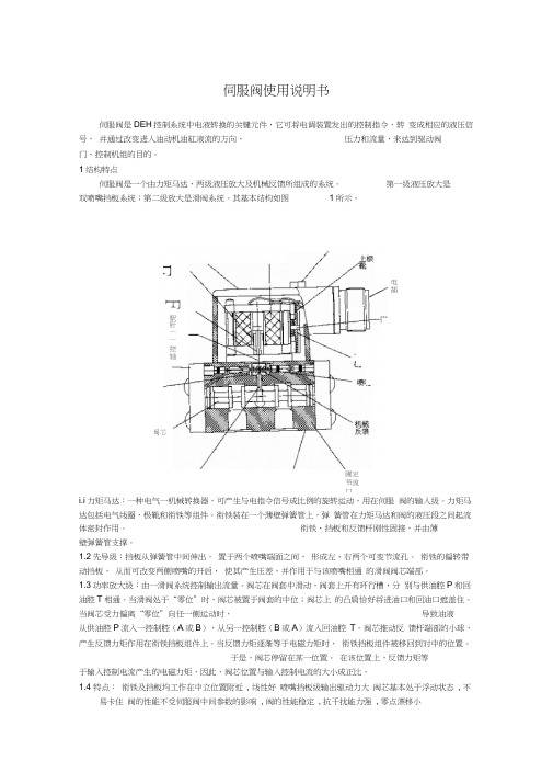
1结构特点伺服阀是一个由力矩马达、两级液压放大及机械反馈所组成的系统。
第一级液压放大是 双喷嘴挡板系统;第二级放大是滑阀系统。
其基本结构如图 1所示。
i.i 力矩马达:一种电气一机械转换器,可产生与电指令信号成比例的旋转运动,用在伺服 阀的输入级。
力矩马达包括电气线圈、极靴和衔铁等组件。
衔铁装在一个薄壁弹簧管上,弹 簧管在力矩马达和阀的液压段之间起流体密封作用。
衔铁、挡板和反馈杆刚性固接,并由薄壁弹簧管支撑。
1.2先导级:挡板从弹簧管中间伸出, 置于两个喷嘴端面之间, 形成左、右两个可变节流孔。
衔铁的偏转带动挡板, 从而可改变两侧喷嘴的开启, 使其产生压差,并作用于与该喷嘴相通 的滑阀阀芯端部。
1.3功率放大级:由一滑阀系统控制输出流量。
阀芯在阀套中滑动,阀套上开有环行槽,分 别与供油腔P 和回油腔T 相通。
当滑阀处于“零位”时,阀芯被置于阀套的中位;阀芯上 的凸肩恰好将进油口和回油口遮盖住。
当阀芯受力偏离“零位”向任一侧运动时, 导致油液 从供油腔P 流入一控制腔(A 或B ),从另一控制腔(B 或A )流入回油腔 T 。
阀芯推动反 馈杆端部的小球,产生反馈力矩作用在衔铁挡板组件上。
当反馈力矩逐渐等于电磁力矩时, 衔铁挡板组件被移回到对中的位置。
于是,阀芯停留在某一位置。
在该位置上,反馈力矩等 于输入控制电流产生的电磁力矩,因此,阀芯位置与输入控制电流的大小成正比。
1.4 特点: 衔铁及挡板均工作在中立位置附近 , 线性好 喷嘴挡板级输出驱动力大 阀芯基本处于浮动状态 , 不易卡住 阀的性能不受伺服阀中间参数的影响 , 阀的性能稳定 , 抗干扰能力强 , 零点漂移小 圃定节流口 F芯阀F駅肝—— 控轴畫的出逵电插2 工作原理:当力矩马达没有电信号输入时,衔铁位于极靴气隙中间,平衡永久磁铁的磁性力。
DDV伺服阀(D633 D634)中文说明书
75
D634 X X
X
B67728-001
X
B67728-002
X
B67728-003
X
!"#$%&'()
9
D633, D634 !
D633 ! !
1
D634 ISO 4401-05-05-0-94 !"# Y4 11.5 ! !" #$ ! !" #$ 2x2 !"#$%&'() 2x2 !"#$%&'()
¡ P ¡ PN
!"#$% !"#$% !"#$% !"#$%
!"#$%&'()*
DDV !"#$%& ! )* !"#$%&'() !"#$%&' !"#$ !" !"#$%&'() !"# !"#$%& !"#$%&' ( !"# !"# !"#$%&'( !"#$%&' !"# $%&' !"#$%& !"#$%&'() !"#$%&'( ! 3 ! ! !"#$% & !"#$%&'(
!"#$%&'()* !"#$%&'()*+, !"#$%&'() PWM !"#$%&' DDV !"#$%&'()*+,-./0-123 !"#$%&' !"#$%&'()*+
施耐德液电伺服阀使用手册说明书
Schneider Servo Valve User ManualSchneider 液电伺服阀使用手册(注意事项)1.使用前准备 (2)1-1. 采购 (2)A. 编码说明 (2)B. 采购注意 (2)2. 伺服阀使用调校 (3)2-1. 伺服阀特性 (3)2-2. 工作条件 (3)2-3. 系统安装伺服阀前置工作 (3)2-4. 装配注意 (3)2-5. 机械调整 (4)2-6. BOE &内置电子放大器调整 (4)1. 使用前准备1-1. 采购 A. 编码说明型号 :028 – 188 (以090为例) 额定流量:0.4 – 800 L/min 材质属性:1-5, 预设 = 1 线圈类型:1-2, 预设 = 2重叠类型:1-2, 预设 = 0 (零重叠) 1 = 正重叠 2-负重叠 重叠特性:1-9, 预设 = 0出厂编号:无预设,视产线、年份,无法指定 内置放大:E1-E5 预设 = 无E1 = ±10V 电压控制E2 = 4...20mA 电流控制P > A E3 = 4...20mA 电流控制P > B E4 = ±10mA 电流控制 E 5= ±20mA 电流控制 B. 采购注意采购Schneider 伺服阀,本伺服阀为电流驱动,可由使用者自行设计放大器或根据需求选择内置放大器E1-E5,或外置放大器BOE ,进行驱动。
未选购内置放大器 需选购或自备 4PIN DIN43563 连接器未选购内置放大器 需选购或自备 7PIN DIN43563 连接器2.伺服阀使用调校2-1.伺服阀特性伺服阀经由本公司提供之放大器=>内建放大器、BOE、HE218 等驱动伺服阀,为了让伺服阀达到最佳特性,驱动电流包含震荡(Dither)信号,伺服阀阀芯于震荡状态(200Hz - 500Hz)保持随时快速移动,此时液压缸会有微幅的移动,需搭配位移传感器保持位置。
电液伺服阀控制器说明书
版本号:B东方汽轮机厂电液伺服阀控制器说明书编号:M902-007000BSM第全册2003年12月编号:M902-007000BSM编希H: _______________校对: -------------------审核: ___________________会签: ------------------- 审定: ---------------------批准: _____________________修改记录表骨口. 序号—Hr*章一节名称页数备注11、, 、.前言122硬件简介1 33功能简介2 44使用说明9 55故障指示2 66性能和参数1 77使用注意说明1DEA伺服卡是为全电调控制系统DEH配套而专门设计的。
该卡采用了16 位单片机80C196芯片和高性能的可编程逻辑阵列CPLD构成控制核心,同时采用了16位A/D和D/A芯片提高转换精度。
电源部分采用了先进的DC-DC隔隔离转换器,确保卡件的工作电源和供电电源的充分隔离,使卡件的电源回路工作有效可靠。
在实现带电插拔的技术上采用了飞利浦的i2c串行总线技术,在校验过程中将LVDT的全关值和全开值存入E2PROM中,从而实现带电插拔。
伺服卡的工作原理是通过采集LVDT勺测量值与控制系统发出的给定值构成比较环节,然后通过Pi 运算,最终输出调节电流控制调节阀门的运动,使阀门的开度到达给定期望到达的位置。
2 硬件简介伺服卡控制器的硬件主要包括伺服卡件和机箱组件:2.1 伺服卡件伺服卡采用的是四层印制板布线工艺,具有极高的EMC抗干扰能力。
板上主要元器件均采用进口优质元件。
2.1.1 CPU采用INTEL先进的16位单片机80C196,运算处理速度极快。
该单片机内置WATCH_DOG能,自恢复能力强。
2.1.2 采用Xilinx 公司的可编程逻辑阵列XC95108作为单片机的接口部件。
该芯片可以将众多的硬逻辑功能用软件实现,访问速度极快。
穆格(Moog) G761 -761系列流量控制伺服阀说明书
为高性能两级设计的流量控制阀,结构简单、坚固,工作可靠,使用寿命长。
2021 年 9 月哪里需要最高水平的运动控制性能和设计灵活性,哪里就能看到穆格技术。
通过协作、创新以及世界级水平的技术解决方案,我们将助您攻克最艰巨的工程难关。
穆格旨在帮助您提高机器的性能,获取超乎想象的新体验。
简介 (2)产品概述 (3)工作原理 (5)技术参数 (6)G761/-761 系列伺服阀 (6)安装图 (11)安装要求 (12)电气接线 (13)背景 (14)流量计算 (14)订货信息 (15)备件及附件 (15)相关产品 (16)关于穆格 (17)订货编码 (19)本产品样本用于为具有一定专业知识的客户提供信息和参数。
为确保获得系统功能和系统的安全性,请对照此样本仔细查看产品的适用性。
文中所述产品如有任何更改,恕不另行通知。
如果有任何疑问,请与穆格公司联系。
Moog 是穆格公司及其子公司的注册商标。
除非另有说明,文中出现的所有商标均为穆格及其子公司所有。
产品概述阀的设计 带阀芯、阀套和干式力矩马达的两级伺服阀安装型式ISO 10372-04-04-0-92P、A、B 和 X 口最大工作压力• 铝制阀体:315 bar (4,500 psi)• 钢制阀体:350 bar (5,000 psi)T 口最大工作压力210 bar (3,000 psi)先导阀喷嘴挡板阀为 35 bar/每一节流边 (500 psi /每一节流边)时的额定流量Δp N 0.5 至 75 l/min (0.125 至 19.5 gpm)从 0 至 100% 行程的阶跃响应时间标准响应型: < 8 ms 高响应型: < 6 ms 超高响应型: < 4 ms在有潜在危险的环境中可以选用本质安全型和防爆型伺服阀。
特殊型号均经过 FM、ATEX、CSA、TIIS 和 IECEx标准认证。
详细信息请联系穆格获取。
文件文件名称说明备注穆格文件号目录G761/-761 系列基本信息注:请访问 /industrialCDL6642手册G761/-761CDS6673G761K/-761K 本质安全型系列CDS6769安装图G761/-761 1系列总体设计CB59420G761K/-761K 系列,2 组线圈CA33637G761/-761 系列流量控制伺服阀是可用作三通和四通节流型流量控制阀,用于四通阀时控制性能更好。
伺服阀说明书(公共版)
版本号:A东方汽轮机厂电液伺服阀控制器说明书编号M902-030000ASM第全册2002年11月编号M902-030000ASM编制校对审核会签审定批准修改记录表目录序号章-节名称页数备注1 0-1 前言 12 0-2 系统简介 33 0-3 硬件简介 14 0-4 工作原理及使用方法 35 0-5 性能与参数 16 0-6 外部接口 27 0-7 使用注意事项 10-1 前言本伺服阀控制器是为驱动汽轮机伺服阀而配套设计的专用装置。
该装置由一套德国威图电磁屏蔽机箱、N(N为系统所用伺服卡块数)块智能伺服卡和一套背板组件构成。
N块智能伺服卡分别插入对应的导槽内,各伺服卡面板上均有发光二极管动态指示卡件的运行状态。
所有进出线均通过背板上的德国PHOENIX 快速连接端子与外设、DEH控制线连接。
通过该装置与DEH系统配合,可完成DEH对汽轮机组的转速、功率的控制。
注:为使本说明书能更详细而又直观地描述伺服阀控制器的配置、安装及各种功能,使用户能更好地接受,本说明书假设N=6(即假设系统所用伺服卡块数为6),实际配置见随控制系统所供的伺服阀控制器图。
0-2 系统简介电液伺服阀控制器由以下模块组合构成:(外形及开孔尺寸见图0-2-1,卡件实际安装位置见所供电液伺服阀控制器图)系统配置原理见图0-2-2、图0-2-3。
图0-2-2图0-2-3电液伺服阀控制器的每一块伺服卡均为智能卡,可以独立接收阀位的给定,并通过对应的位移传感器和固化在卡件上的程序完成阀位给定与阀位反馈的比较、PI运算及输出驱动电流的闭环阀位调节控制。
伺服卡具有阀位显示、自动校验、手动控制等输入输出功能,通过外部的操作系统可以很方便地显示实时的阀位开度(%),并且可以进行阀门的自动校验和手动控制。
本系统配置N块伺服卡,故可以同时对N套阀位进行调节控制。
0-3 硬件简介电液伺服阀控制器的硬件主要包括伺服卡和机箱组件。
1伺服卡硬件伺服卡采用四层印制板布线工艺,具有极高的EMC抗干扰能力。
- 1、下载文档前请自行甄别文档内容的完整性,平台不提供额外的编辑、内容补充、找答案等附加服务。
- 2、"仅部分预览"的文档,不可在线预览部分如存在完整性等问题,可反馈申请退款(可完整预览的文档不适用该条件!)。
- 3、如文档侵犯您的权益,请联系客服反馈,我们会尽快为您处理(人工客服工作时间:9:00-18:30)。
伺服阀使用说明书
伺服阀是DEH控制系统中电液转换的关键元件,它可将电调装置发出的控制指令,转变成相应的液压信号,并通过改变进入油动机油缸液流的方向、压力和流量,来达到驱动阀门、控制机组的目的。
1 结构特点
伺服阀是一个由力矩马达、两级液压放大及机械反馈所组成的系统。
第一级液压放大是双喷嘴挡板系统;第二级放大是滑阀系统。
其基本结构如图1所示。
1.1 力矩马达:一种电气—机械转换器,可产生与电指令信号成比例的旋转运动,用在伺服阀的输入级。
力矩马达包括电气线圈、极靴和衔铁等组件。
衔铁装在一个薄壁弹簧管上,弹簧管在力矩马达和阀的液压段之间起流体密封作用。
衔铁、挡板和反馈杆刚性固接,并由薄壁弹簧管支撑。
1.2 先导级:挡板从弹簧管中间伸出,置于两个喷嘴端面之间,形成左、右两个可变节流孔。
衔铁的偏转带动挡板,从而可改变两侧喷嘴的开启,使其产生压差,并作用于与该喷嘴相通的滑阀阀芯端部。
1.3 功率放大级:由一滑阀系统控制输出流量。
阀芯在阀套中滑动,阀套上开有环行槽,分别与供油腔P和回油腔T相通。
当滑阀处于“零位”时,阀芯被置于阀套的中位;阀芯上的凸肩恰好将进油口和回油口遮盖住。
当阀芯受力偏离“零位”向任一侧运动时,导致油液从供油腔P流入一控制腔(A或B),从另一控制腔(B或A)流入回油腔T。
阀芯推动反馈杆端部的小球,产生反馈力矩作用在衔铁挡板组件上。
当反馈力矩逐渐等于电磁力矩时,衔铁挡板组件被移回到对中的位置。
于是,阀芯停留在某一位置。
在该位置上,反馈力矩等于输入控制电流产生的电磁力矩,因此,阀芯位置与输入控制电流的大小成正比。
1.4 特点:
●衔铁及挡板均工作在中立位置附近,线性好
●喷嘴挡板级输出驱动力大
●阀芯基本处于浮动状态,不易卡住
●阀的性能不受伺服阀中间参数的影响,阀的性能稳定,抗干扰能力强,零点漂移小
2 工作原理:
当力矩马达没有电信号输入时,衔铁位于极靴气隙中间,平衡永久磁铁的磁性力。
当有欲使调节阀动作的电气信号由伺服放大器输入时,力矩马达的线圈中有电流通过,产生一磁场,在磁场作用下,产生偏转力矩,使衔铁旋转,同时带动与之相连的挡板转动,此挡板伸到两个喷嘴中间。
在正常稳定工况时,挡板两侧与喷嘴的距离相等,两侧喷嘴泄油面积相等,使喷嘴两侧的油压相等。
当有电气信号输入,衔铁带动挡板转动时,挡板移近一只喷嘴,使这只喷嘴的泄油面积变小,流量变小,喷嘴前的油压变高,而对侧的喷嘴与挡板间的距离变大,泄油量增大,使喷嘴前的压力变低,这样就将原来的电气信号转变为力矩产生机械位移信号,再转变为油压信号,并通过喷嘴挡板系统将信号放大,挡板两侧喷嘴前油压与下部滑阀的两个端部腔室相通,当两个喷嘴前的油压不等时,滑阀两端的油压也不相等,使滑阀移动,由滑阀上的凸肩所控制的油口开启或关闭,从而控制通向油动机活塞下腔的高压油,以开大调节阀的开度,或者将活塞下腔通向回油,使活塞下腔的油泄去,由弹簧力关小调节阀。
为了增加系统的可靠性,在伺服阀中设置了反馈弹簧,使伺服阀有一定的机械零偏(可外调)。
在运行中如突然发生断电或失去电信号时,靠机械力最后可使滑阀偏移一侧,使调节阀关闭。
3 技术参数:(MOOG-J761)
额定流量:63 lpm
分辨率:<0.5%
滞环:<3%
最高允许工作压力:32MPa
正常工作压力:14MPa
工作温度:-29~135℃
密封材料:氟橡胶
线圈电阻:80Ω(单线圈)40Ω(两线圈并联)
额定电流:±40mA
接线方式:A、C(+)B、D(-)
4 注意事项:
4.1 油液建议使用温度为35℃~55℃。
其酸值、氯含量、水含量、电阻率等指标符合要求。
4.2为了系统和元件的最佳寿命,系统油液颗粒度应把保持于SAE等级2、NAS-1638等级6或ISO-15/12。
4.3 伺服阀出厂前都经过严格的性能测试。
如伺服阀发生故障,用户不得自行解体,而应返回制造商、研究所的伺服阀维修中心进行修理、排障和调整。
4.4伺服阀的装卸
4.4.1安装伺服阀前应确认:
●安装面无污粒附着;
●供油和回油管路正确;
●底面各油口的密封圈齐全;
●定位销孔位正确。
4.4.2伺服阀从液压系统卸下时,必须做到:
●将阀注满清洁工作液,装上运输护板;
妥善保护好安装座上各油口,以免污物侵入。
4.5伺服阀的使用
4.5.1伺服阀外接导线应屏蔽,并良好接地。
4.5.2阀的极性应按使用说明书规定联接。
4.5.3阀的输入电流不允许超过制造厂允许值。
4.5.4伺服阀在未供油压的情况下,应尽量避免输入交变电信号。