Optimal Routing in Trivalent Cayley Graph Network
Finding Optimal Paths in MREP Routing

Finding Optimal Paths in MREP RoutingRudolf Fleischer1Mordecai Golin1Chin-Tau Lea2∗Steven Wong2 1Dept of CS,HKUST,Clear Water Bay,Hong Kong,[rudolf,golin]@t.hk2Dept of EEE,HKUST,Clear Water Bay,Hong Kong,eelea@t.hkKeywords:approximation algorithm,graph algorithms,computational complexityAbstractMaximum Residual Energy Path(MREP)routing has been shown an effective routing scheme for energy conservation in battery powered wireless networks.Past studies on MREProuting are based on the assumption that the transmitting node consumes power,but the re-ceiving node does not.This assumption is false if acknowledgement is required as occurs,forexample,in some Bluetooth applications.If the receiving node does not consume power then the MREP routing problem for a single message is easily solvable in polynomial time using a simple Dijkstra-like algorithm.We furthershow in that when the receiving node does consume power the problem becomes NP-completeand is even impossible to approximate with an exponential approximation factor in polynomialtime unless P=NP.1IntroductionRecent advances in wireless technologies,such as Bluetooth[10],have made it easy and practical to construct an ad hoc network for novel applications—a surveillance network,a wireless tag network in a grocery store,and a sensor network to monitor environment dangerous conditions are just a few examples.Battery power is a precious resource for each wireless device(except the wired gateway com-puter)and energy conservation is critical for such a network.Routing will play an important role in energy conservation.This issue has been studied extensively in the past[2,3,9,11,14,15,16].A central part of any routing study is the definition of the path metric.Some metrics combine both delay and power consumption,whereas others focus on maximizing the system life time and ignore the delay.When delay is less a concern than system life,Maximum Residual Energy Path(MREP)routing has been shown an effective scheme for energy conservation[2,3,4].In MREP routing,the best path is one that maximizes the energy of that node on the path with the least energy after sending the message.Previous work on MREP routing concentrated on heuristics for a constant stream of messages to be routed through the network[2,3,4],the case of hybrid cost functions that try to balance total energy consumption and energy drain at a single node[12,15],or just studied local routing heuristics in a distributed system[17].All these studies have been based on the assumption that sending packets requires energy,but receiving packets does not.In this case,we show that theu 22611211131211151516x 32Pw s 686t 815vFigure 1:A routing network.Nodes are labeled by their energy.Outgoing edges are labeled by the send cost along the edge,and incoming edges are labeled by the acknowledgement cost.The path P =(s,w,u,x,t )has D (P )=1(with node x being the bottleneck)and is therefore legal.MREP routing problem for a single message is reducible to the max-bandwidth path problem and therefore polynomial-time solvable using a standard Dijkstra-type algorithm (a similar algorithm is sketched in [2]).However,the assumption of energy-free reception is not always justified.Ad hoc networking technologies normally include energy-conservation states.Between two transmissions,nodes in the network may enter the energy-conservation state (sleeping)state.A sleeping node along the chosen path has to be waken up first.The process requires a hand-shaking packet exchanged between the sender and the receiver.Sending a hand-shaking packet by the receiver will cost energy.Another example is if the ad hoc network has very noisy connections (like an earthquake monitoring sensor network or a battlefield network),hop-by-hop acknowledgement may be used.For every packet received,the receiver must send back an acknowledgement packet.This costs energy.We show that in this case the MREP routing problem for a single message is NP-complete and is impossible even to approximate with an exponential approximation factor in polynomial time unless P =NP .After defining the MREP routing problem in Section 2,we will show in Section 3that it can be efficiently solved in networks without acknowledgement costs by a simple transformation to the max-bandwidth path problem.We then show in Section 4that the general problem with acknowledgement costs is NP-complete and very hard to approximate.2DefinitionsWe can model the MRE routing problem as follows.Let G =(V,E )be a directed graph where V is a set of vertices (wireless nodes)and E is a set of directed edges (connections).Initially,each vertex u has a battery charged with energy E u ≥0.This energy will be consumed by sending or acknowledging messages.We usually just speak of the energy of a node.With each edge e =(u,v )we associate two costs,the sending cost s e (or s u,v )for sending a message along e ,i.e.,the power used up by the sender when transmitting the full message,and the acknowledgement cost r e (or r u,v )for receiving a message,i.e.,the power used by the receiver to transmit an acknowledgement message back to the sender.Sending a message along e =(u,v )will reduce E u ,the energy of u ,by s e ,and it will reduce E v by r e .Of course,sending a message is only possible if neither node energies become negative.Normally,s e and r e will depend on the distance between the vertices and on the size of the message (in our definition we assume all messages have2unit size),but that is not important for our results.When sending a message from a vertex s to a vertex t in G we can usually choose between many different paths along which we could route the message.We are interested in paths that leave a high energy in all the nodes on the path,i.e.,we try to avoid situations where routing a message would use up all the energy of one node.Otherwise,we might have trouble routing the next message(the network could even become disconnected).Formally,if we route a message along a path P=(v1,v2,...,v k−1,v k)in G,where v1,...,v k are vertices and(v1,v2),...,(v k−1,v k)are edges,then each node on P loses some energy due to the send and acknowledgement costs.Let R u denote the residual energy of u after routing themessage.If P is simple then R v1=E v1−s v1,v2,R vi=E vi−r vi−1,v i−s vi,v i+1for i=2,...,k−1,and R vk =E vk−r vk−1,v k.Otherwise,P contains some vertex(or vertices)several times,and thenwe have to add up all the send and acknowledgement costs for that vertex.We now define the minimum residual energy(MRE)of P,denoted by D(P),to beD(P)=mini=1,...,k {R vi}.Note that we can only send a message along P if all nodes on P have non-negative residual energy,i.e.,D(P)≥0.We call such a path legal.See Fig.1for an example.We call a path optimal if it has maximum MRE among all paths that route a message from a given start vertex to a given end vertex.Routing along a nonsimple path is obviously never a good idea,so optimal paths are always simple.Our goal is tofind optimal s−t paths.MREPP(Maximum Residual Energy Path Problem)Input:A directed graph G=(V,E)with vertex energies E u,and send costss u,v and acknowledgement costs r u,v on the edges(u,v).There are also twodistinguished vertices s(source)and t(destination).Output:An s−t path in G that maximizes D(P)among all s−t paths P inG.3MREPP Without Acknowledgement Costs3.1The Max-Bandwidth ProblemIn this section we quickly review the max-bandwidth problem for graphs with bandwidth constraints on the edges and its solution.We will present an algorithm that will be used in the next section as a subroutine to solve MREPP without acknowledgement costs.Let G=(V,E)be a directed graph such that associated with each edge(u,v)∈E there is a bandwidth b(u,v)≥0.Let P=(v1,v2,...,v k−1,v k)be a path in G.The bandwidth of P is B(P)=min1≤i<k b(v i,v i+1),i.e.,the smallest bandwidth among all edges on P(also called the bottleneck of P).Given s,t∈V,the max-bandwidth problem is tofind a path from s to t that maximizes B(P).This problem has been well studied and it is well known that such a path can be found using a simple modification of Dijkstra’s shortest path algorithm[5,6].A good history and description of the modified algorithm using modern notation is available in[13].The standard implementation of this algorithm runs in O(|E|log|V|)time;with more sophisticated data structures this can be further reduced to O(|E|+|V|log|V|)[7].33632443t ′t x wu s v43674463t ′t x w u v s 376(a)(b)Figure 2:(a)The network of Fig.1with zero acknowledgement costs and residual node energies replacedby bandwidth constraints on the edges.There are several max-bandwidth s −t ′paths of cost 3.One such path is s,u,t,t ′,with bottleneck (u,t ).(b)The max-bandwidth spanning tree computed by the modified Dijkstra’s algorithm.Note that every path in the tree from s to a node w is a max-bandwidth s −w path.1.Transform G =(V,E )into G ′=(V ′,E ′)by adding vertex t ′and edge (t,t ′).Setb (u,v )=E u −s u,v for edges (u,v )∈E ,and b (t,t ′)=E t .e a max-bandwidth algorithm to find P ′,a max-bandwidth s −t ′path in G ′.3.Return P ,the s −t path in G corresponding to P ′.Figure 3:Algorithm for solving MREPP in networks without acknowledgement costs.3.2Solving MREPPIn this section we describe how to find optimal MRE paths when there are no acknowledgement costs for messages,i.e.,r e =0for all edges e .To solve this problem we run the max-bandwidth algorithm from the previous section on the graph obtained from the given network by defining the bandwidth of an edge as the residual energy that would remain in the node if we used the edge to route the message.Assume we want to find an optimal s −t path,where s and t are nodes of the given network G =(V,E ).Without acknowledgement costs,the residual energy of a node v i on an s −t path P =(s =v 1,v 2,...,v k −1,v k =t )is R v i =E v i −s v i ,v i +1,for i =1,...,k −1,and it is R t =E t for the node t .We now transform G into a new graph G ′by adding a new node t ′and a new edge (t,t ′)with bandwidth equal to E t .For all other edges (u,v )of G ′we define the bandwidth to be b (u,v )=E u −s u,v .Fig.2(a)shows the transformed graph of Fig.1(when all acknowledgement costs are set to zero).Obviously,there is a one-to-one correspondence between s −t paths in G and s −t ′paths in G ′.Moreover,if P is an s −t path in G and P ′is the corresponding s −t ′path in G ′then D (P )=B (P ′).For example,in Fig.1the path P =(s,u,t )has D (P )=3(ignoring the acknowledgement costs),and the corresponding path P ′=(s,u,t,t ′)has B (P ′)=3.To find the max-bandwidth path in G ′,we can use the max-bandwidth algorithm from the previous section.The tree path from s to t ′corresponds to the optimal MRE s −t simple path in G .In Fig.3we summarize the algorithm to compute an optimal MRE path for networks without acknowledgement costs.For example,running the modified Dijkstra algorithm on the transformed graph in Fig.2(a),4···Figure4:The NP-completeness reduction from3-SAT.We try to send a message from s to t.This is possible if and only if the given3-SAT formula is satisfiable.The connections between the gadgets V i and K j are only indicated.gives the spanning tree in Fig.2(b).In this tree,the max-bandwidth s−t′path is P′=(s,u,t,t′) with bandwidth B(P′)=3.Thus,an optimal MRE s−t path in the graph in Fig.1is P=(s,u,t) with D(P)=3(ignoring acknowledgement costs).4The NP-Completeness ProofIn this section we show that MREPP is NP-complete.We actually show that even deciding whether there exists a legal routing path between two specified nodes is ter we will slightly modify the construction in the proof of the theorem to show that approximating MREPP is also very difficult.We will use reduction from3-SAT,so wefirst quickly review the3-SAT problem[8].An instance of3-SAT is a set U={x1,x2,...,x n}of variables and a formula which is given as a collection C1,C2,...C m⊆2U of clauses.A literal is either a variable x i or its negation¯x i;in the former case the literal is positive,in the latter case it is negative.Each clause C j={ℓj,1,ℓj,2,ℓj,3} consists of three literals.A truth assignment is a functionφ:U→{T,F}.A positive literal x i is satisfied byφifφ(x i)=T,a negative literal¯x i is satisfied ifφ(x i)=F.A clause is satisfied if at least one of its literals is satisfied.A formula is satisfiable if there is a truth assignment that satisfies all of its clauses.Deciding whether such an assignment exists is NP-complete.Theorem1MREPP is NP-complete.Proof.Since we can easily check whether a given routing leaves at least a specified minimum residual energy in the nodes along the routing path,MREPP is in NP.We will prove that MREPP is NP-hard by showing a polynomial-time reduction from3-SAT to MREPP.That is,given an instance of3-SAT we will in polynomial time construct an instance of MREPP that has a legal path from s to t if and only if the3-SAT instance is satisfiable.We now describe how to transform an instance of3-SAT to an instance of MREPP.Let the formula F be given as a set of m clauses C j={ℓj,1,ℓj,2,ℓj,3},for j=1,...,m,over n variables x1,...,x n.We construct a directed graph as in Fig.4.It contains two kinds of gadgets.For each variable x i,i=1,...,n,we have the variable gadget V i(see Fig.5).In this gadget,the message can be routed along one of two parallel paths.If the message is routed along the upper path in the figure then we interpret this as setting x i to T;therefore,we call this path the true-path.Similarly, the lower path corresponds to the setting x i=F,so this path is called the false-path.After the message has passed all the variable gadgets(and all variables have been assigned a truth value)it must be routed through the clause gadgets K j,for j=1,...,m.To satisfy a clause, we must route the message through one of three parallel paths,each corresponding to one of the literals of the clause(see Fig.6).Each of these paths moves back to a node in the variable gadget of the respective literal.If the clause contains the positive literal x i then the clause gadget connects to the node v i,j on the false-path and if the clause contains the negative literal¯x i then the clause5Figure5:The variable gadget V i.Routing the message along the upper(lower)path corresponds to setting x i to T(F).The dotted line shows the interaction with clause C j if that clause contains the literal x i.j,3k j,1Figure6:The clause gadget K j.Ifℓj,p,for p=1,2,3,is the variable x i then k j,p is the node v i,j in V i; otherwise,it is the node¯v i,j.gadget connects to the node¯v i,j on the true-path.Choosing the node energies and the send and acknowledgement costs appropriately(we will do this later),each node in a variable gadget can route the message at most once.Of course,if the formula is satisfiable then we can always route the message along the path corresponding to the literal in the clause that is true in the satisfying assignment.Thus,the existence of a satisfying assignment for the formula induces an s−t routing path through the network.If all the nodes have sufficient energy for routing the message then this path is also legal.Fig.7shows the complete network for the formula(x1∨¯x2∨x3)∧(¯x1∨¯x2∨x3), together with the s−t path corresponding to the satisfying truth assignment x1=T,x2=F,and x3=T.It remains to show that every s−t path induces a satisfying assignment for the formula.This can be guaranteed by a clever choice of the node energies and the send and acknowledgement costs for the edges.Let c≥1befixed.For the correctness of our reduction,the actual value of c is not important.But to get a polynomial-time reduction we must restrict c to a value that can be computed in polynomial time.All nodes have energy4c−1.The edge(s,y1)has send cost s s,y1=3c and acknowledgementcost r s,y1=1.The edge(w m,t)also has send cost s wm,t=3c and acknowledgement cost r wm,t=1.In the variable gadgets V i,for i=1,...,n,the incoming edge at y i has acknowledgement cost6V1K2K1V2V3Figure7:The network we construct for the formula(x1∨¯x2∨x3)∧(¯x1∨¯x2∨x3).The dotted line is the legal s−t path corresponding to the satisfying truth assignment x1=T,x2=F,and x3=T.1,and the outgoing edges of y i have send cost s yi,¯v i,m =s yi,v i,m=3c−1and acknowledgementcost r yi,¯v i,m =r yi,v i,m=2c.The incoming edges of z i have send cost s¯vi,1,z i=s vi,1,z i=c andacknowledgement cost r¯vi,1,z i =r vi,1,z i=1,and the outgoing edge at z i has send cost3c−1.Allother edges on the true-path and the false-path have send cost s¯vi,j,¯v i,j−1=s vi,j,v i,j−1=c andacknowledgement cost r¯vi,j,¯v i,j−1=r vi,j,v i,j−1=2c,for j=m,...,2.Thus,routing through V ileaves residual energy c−1in all nodes on the routing path(which is not enough to route the message a second time).In the clause gadgets K j,for j=1,...,m,the incoming edges of u j have acknowledgementcost1,and the outgoing edges have send cost s uj,k j,1=s uj,k j,2=s uj,k j,3=3c−1.The incomingedges at w j have acknowledgement cost r kj,1,w j =r kj,2,w j=r kj,3,w j=1,and the outgoing edgeshave send cost3c−1.Thus,routing through K j leaves residual energy c−1in all nodes on the routing path.It is now easy to see that there is no legal s−t path that does not correspond to a satisfying assignment.Consider an arbitrary legal s−t path P.P must enter the gadget V i at y i,for i=1,...,n,follow either the true-path or the false-path(because the nodes do not have enough energy to send the message along one of the edges going to a node in a clause gadget),and leave V i at node z i.After the last gadget V n,all nodes z i have residual energy c−1,so P cannot pass through these nodes again later.Now P enters thefirst clause gadget K1.It can only follow an edge to a node v in some V i that was not used before because the nodes in V i do not have enough energy to receive and send two messages(or the same message twice).From v,which is either v i,1or¯v i,1,the message cannot be routed to z i again(because the message passed already once through z i).So it must go back to K1from v,i.e.,it goes to w1.But then P has satisfied clause C1because v corresponds to a true literal.Note that this argument is the reason why we ordered the nodes on the true-path(and false-path)in reverse order.From w1,P enters the second clause gadget K2.Again,it must satisfy the clause by choosing an edge to either v i,2or¯v i,2in some V i that coresponds to a true literal.And again,it must immediately return to K2because otherwise it would have to leave V i either via z i or via w1(if x17is also a literal in C1),and these both cases are not possible.Continuing this argument,we can prove by induction on j=1,...,m that P must enter K j at u j and leave it at w j,so P indeed induces a satisfying assignment for all clauses.Also,all nodes on P will have energy c−1after the routing,so we have D(P)=c−1.Thus,P is legal if c is at least1.Finally,we must show that our reduction is polynomial-time.Our network has O(nm)nodes and O(nm)edges that can all be computed in polynomial time from the given description of the formula. Also,all edge costs and node energies can be computed in polynomial time if c=O(2poly(nm)). Choosing c=1actually suffices for the correctness of the construction.We need other values of c later in the proof of non-approximability.2 In the proof of the theorem above,some of the edges have a higher acknowledgement than send cost.If this was not allowed in a more restrictive(but more realistic)routing scenario we could modify the construction by adding a new node with energy4c−1in the middle of each edge,where the incoming edge has acknowledgement cost1and the outgoing edge has send cost3c−1.With another slight modification of the construction in the proof above we can also prove that approximating MREPP is very difficult.Theorem2MREPP cannot be approximated within a factor of O(2poly(n))in polynomial time unless P=NP,where n is the number of nodes in the network.Proof.We prove the theorem by showing that a polynomial-time approximation algorithm for MREPP with an approximation ratio ofρ=O(2poly(n))would enable us to solve3-SAT in polynomial time.We use essentially the same construction as in the proof of Theorem1.We just add one more edge from s to t,with send cost and acknowledgement cost4c−2.In this network,there always exists a legal s−t path with minimum residual energy1,namely the edge(s,t).Another path of minimum residual energy c exists if and only if the formula F represented by the network is satisfiable.Since we could choose c=2ρ=O(2poly(n)),any approximation algorithm for MREPP with approximationρcould decide the satifiability of F.2 5ConclusionsWe have shown that MREPP is a very difficult problem in networks with acknowledgement costs. But this is only the problem of routing a single message.What we actually want is a good routing scheme for many messages,either in an online setting(and then we would like to use either com-petitive analysis or some probabilistic analyis)or in a situation where we have a batch of messages for which we want tofind a good routing schedule.Since these problems seem to be rather hard, we might concentrate onfinding heuristics that work well in practice.References[1]D.Bertsekas and R.Gallager.Data Networks.Prentice-Hall,2nd edition,1987.[2]J.-H.Chang and L.Tassiulas.Routing for maximum system lifetime in wireless ad-hoc net-works.In Proceedings of the37th Annual Allerton Conference on Communication,Control, and Computing,Monticello,IL,Sep.1999.8[3]J.-H.Chang and L.Tassiulas.Energy conserving routing in wireless ad-hoc networks.In Pro-ceedings of the19th Annual IEEE Conference on Computer Communications(INFOCOM 2000),vol.1,pp.22–31,Tel Aviv,Israel,March2000.[4]J.-H.Chang and L.Tassiulas.Fast approximate algorithms for maximum lifetime routing inwireless ad-hoc networks.In Networking,vol.1815of Springer LNCS,pp.702–713,2000. [5]T.Cormen,C.Leiserson,and R.Rivest.Introduction to Algorithms.McGraw-Hill and MITPress,1990.[6]J.Edmonds and R.M.Karp,Theoretical improvements in algorithmic efficiency for networkflow problems.Journal of the ACM19(2):248–264,1972.[7]M.Fredman and R.Tarjan.Fibonacci heaps and their uses in improved network optimizationproblems.Journal of the ACM,34:596–615,1987.[8]M.R.Garey and puters and Intractability:A Guide to the Theory ofNP-Completeness.W.H.Freeman and Company,New York,1979.[9]J.Gomez,A.T.Campbell,M.Naghshineh,and C.Bisdikian.Power aware routing in wirelesspacket networks.In Proceedings of the Sixth International Workshop on Mobile Multimedia Communications(MoMuC’99),pp.380-383,San Diego,California,Nov.1999.[10]J.C.Haartsen and S.Mattisson.Bluetooth—A new low-power radio interface providingshort-range connectivity.IEEE Proceedings,88(10):1651–1661,2000.[11]D.Johnson and D.Maltz.Dynamic source routing in ad hoc wireless networks.Chapter5in T.Imielinski and H.Korth,eds.,Mobile Computing,pp.153–181,Kluwer Academic Publishers, 1996.[12]K.Kalyan Kumar and A.Chockalingam.Energy efficient routing in wireless ad-hoc networks.Url /523912.html.[13]N.Malpani and J.Chen.A note on practical constructions of maximum bandwidth paths.Url/course-info/cpsc629/chen/notes/,2002.[14]S.Murthy and J.J.Garcia-Luna-Aceves.An efficient routing protocol for wireless networks.Mobile Networks and Applications,1(2):183–197,1996.[15]S.Singh,M.Woo,and C.S.Raghavendra.Power-aware routing in mobile ad hoc networks.In Proceedings of the Fourth Annual International Conference on Mobile Computing and Net-working(MOBICOM’98),pp.181–190,Dallas,Texas,Oct.1998.[16]I.Stojmenovic and X.Lin.Power aware localized routing in wireless networks.In Proceedingsof the14th IEEE International Parallel and Distributed Processing Symposium(IPDPS’00), pp.371–376,Cancun,Mexico,May2000.[17]K.Woo, C.Yu, D.Lee,H.Y.Youn,and B.Lee.Non-blocking,localized rout-ing algorithm for balanced energy consumption in mobile ad hoc networks.Url /510965.html.9。
高分子专业英语词汇汉译英
--- 均方末端距mean-aquare end-to-end distance 均方末端距- 非交联的uncross-linked 非交联的- 三维有序的three-dimensionally ordered 三维有序的- 三乙基硼氟酸羊triethyloxonium-borofluoride 三乙基硼氟酸羊- 射线光X-ray x射线 x光- 缨状微束理论fringed-micelle theory 缨状微束理论- 折叠链片晶理论folded-chain lamella theory 折叠链片晶理论- 逐步聚合step-growth polymerization 逐步聚合(表面)发粘的,粘连性tacky (表面)发粘的 ,粘连性(空间)排布,排列arrangement (空间)排布,排列(链)引发initiation (链)引发(链)终止terminate (链)终止(链)转移,(热)传递transfer (链)转移,(热)传递(生)面团,揉好的面dough (生)面团,揉好的面(作用于)分子间的intermolecular (作用于)分子间的氨基,氨基的amino 氨基,氨基的氨基甲酸酯urethane 氨基甲酸酯把…相互连接起来连接interlink 把…相互连接起来连接半晶semicrystalline 半晶半径radius 半径饱和saturation 饱和苯基锂phenyllithium 苯基锂苯基钠phenyl sodium 苯基钠变化,改变variation 变化,改变变形deformation 形变变形性,变形能力deformability 变形性,变形能力表面活性剂surfactant 表面活性剂表征成为…的特征characterize 表征成为…的特征玻璃(态)的glassy 玻璃态的玻璃化温度glass transition temperature 玻璃化温度玻璃态glassy 玻璃(态)的玻璃态的glassy state 玻璃态不饱和的unsaturated 不饱和的不规则性,不均匀的irregularity 不规则性,不均匀的不均匀的,非均匀的heterogeneous 不均匀的,非均匀的不了或缺的indispensable 不了或缺的不完全的imperfect 不完全的参数parameter 参数侧基pendant group 侧基缠结,纠缠entanglement 缠结,纠缠产率yield 产率超声波ultrasonic 超声波超速离心(分离)ultracentrifugation 超速离心(分离)撤出evacuate 撤出沉淀,澄清settle 沉淀,澄清沉降(法)sedimentation 沉降(法)衬里,贴面line 衬里,贴面成分ingredient 成分成型shaping 成型尺寸dimension 尺寸尺寸稳定性dimensional stability 尺寸稳定性稠度,粘稠度consistency 稠度,粘稠度纯度purity 纯度醇(碱金属)烯催化剂Alfin catalyst 醇(碱金属)烯催化剂催化剂,触媒catalyst 催化剂,触媒脆的,易碎的brittle 脆的,易碎的错位,位错dislocation 错位,位错大分子,高分子macromelecule 大分子,高分子单官能度的monofunctional 单官能度的单键single bond 单键单体monomer 单体单轴的uniaxial 单轴的弹性模量elastic modulus 弹性模量弹性体elastomer 弹性体弹性指数slastic parameter 弹性指数当量的,化学计算量的stoichiometric 当量的,化学计算量的导电材料conductive material 导电材料等规立构的isotactic 等规立构的丁二烯butadiene 丁二烯丁基锂butyllithium 丁基锂定向,取向orient 定向,取向定向orientation 定向动力学kinetics 动力学动力学链长kinetic chain length 动力学链长断裂rupture 断裂堆积物,沉积deposit 堆积物,沉积堆砌packing 堆砌多分散的polydisperse 多分散的多分散性polydispersity 多分散性多官能度的polyfunctional 多官能度的多孔性,孔隙率porosity 多孔性,孔隙率二(元)胺diamine 二(元)胺二(元)醇diol 二(元)醇二(元)酸diacid 二(元)酸二次成型secondary shaping operation 二次成型二聚物(体)dimer 二聚物(体)二烯烃diolefin 二烯烃二元的dibasic 二元的反应物,试剂reactent 反应物,试剂反应性,活性reactivity 反应性,活性反应性的,活性的reactive 反应性的,活性的芳香(族)的aromatic 芳香(族)的非弹性的nonelastic 非弹性的分级fractionation 分级分解,分散,分离disintegrate 分解,分散,分离分解decomposition 分解分类(法)categorization 分类(法)分散剂dispersant 分散剂分子量molecular weight distribution 分子量分布分子量分布molecular weight 分子量粉状的powdery 粉状的副作用side reaction 副作用改性modify 改性隔离基团spacer group 隔离基团各项同性的isotropic 各项同性的功能聚合物functional polymer 功能聚合物功能聚合物functionalized polymer 功能聚合物共聚(合)copolymerization 共聚(合)共聚物copolymer 共聚物构象conformation 构象固有的intrinsic 固有的官能团functional group 官能团光敏剂photosensitizer 光敏剂光气,碳酰氯phosgene 光气,碳酰氯光散射light scattering 光散射合成synthesis 合成合成synthesize 合成合成的synthetic 合成的核磁共振nuclear magnetic resonance 核磁共振核径迹探测器nuclear track detector 核径迹探测器红外光谱法infrared spectroscopy 红外光谱法花纹,图样式样pattern 花纹,图样式样缓释剂corrosion inhibitor 缓释剂机理mechanism 机理基体,结晶crystal 基体,结晶基体,母体,基质,矩阵matrix 基体,母体,基质,矩阵挤出extrusion 注射成型挤压squeeze 挤压加成聚合物,加聚物addition polymer 加成聚合物,加聚物加工,成型processing 加工,成型加重,恶化aggravate 加重,恶化夹杂(带)的occluded 夹杂(带)的假定的,理想的,有前提的hypothetical 假定的,理想的,有前提的间歇式的intermittent 间歇式的碱金属alkali metal 碱金属键断裂能bond dissociation energy 键断裂能降解depropagation 降解交联crosslinking 交联胶体colloid 胶体搅拌agitation 搅拌结构,组织texture 结构,组织结晶的crystalline 晶体,晶态,结晶的,晶态的结晶性,结晶度crystallinity 结晶性,结晶度解除,松开release 解除,松开解聚depolymerization 解聚介质中等的,中间的medium 介质中等的,中间的界限,范围boundary 界限,范围晶体,晶态,结晶的,晶态的crystalline 结晶的竞聚率reactivity ratio 竞聚率聚苯烯polypropylene 聚苯烯聚苯乙烯polystyrene 聚苯乙烯聚丁烯polybutene 聚丁烯聚合(物)的polymeric 聚合(物)的聚合度degree of polymerization 聚合度聚合物【体】,高聚物polymer 聚合物【体】,高聚物聚氯乙烯polyvinylchloride 聚氯乙烯聚酰胺polyamide 聚酰胺聚乙烯polyethylene 聚乙烯聚乙烯醇polyvinyl alcohol 聚乙烯醇聚酯化(作用)polyesterification 聚酯化(作用)开链unzippering 开链开始,着手commence 开始,着手抗静电剂antistatic agent 抗静电剂抗氧剂antioxidant 抗氧剂抗张强度tensile strength 抗张强度控制释放controlled release 控制释放口模成型dieforming 口模成型扩散diffuse 扩散拉直,拉长stretch 拉直,拉长冷冻水chilled water 冷冻水离解dissociate 离解离心centrifuge 离心离子ion exchange resin 离子交换树脂离子的ionic polymerization 离子型聚合离子交换树脂ion 离子离子型聚合ionic 离子的理想的,概念的ideal 理想的,概念的力学性能,机械性能mechanical property 力学性能,机械性能立构规整性【度】srereoregularity 立构规整性【度】连锁反应chain reaction 连锁反应链段segment 链段链段segment 链段链间的interchain 链间的链终止chain termination 链终止流动性mobility 流动性流体静力学hydrostatic 流体静力学硫化vulcanization 硫化络合物complex 络合物氯(气)chlorine 氯(气)氯乙烯vinyl 乙烯基(的)密度density 密度密封seal 密封模塑成型moulding 模塑成型模型model 模型逆流countercurrent 逆流黏弹态viscoelastic 黏弹性的黏弹性的viscoelastic state 黏弹态黏度viscosity average molecular weight 黏均分子量黏均分子量viscosity 黏度黏流态viscofluid state 黏流态凝胶gel 凝胶农药,化肥agrochemical 农药,化肥排列成行align 排列成行配方formulation 配方喷洒sprinkle 喷洒片晶platelet 片晶平衡equilibrium 平衡潜在的latent 潜在的嵌入,埋入,包埋imbed 嵌入,埋入,包埋强度strength 强度氢(气)hydrogen bonding 氢键氢键hydrogen 氢(气)取代,代替substitution 取代,代替缺陷defect 缺陷热成型thermoforming 热成型热传递heat transfer 热传递热固性的thermoset 热固性的热解pyrolysis 热解热力学地thermondynamically 热力学地热塑性的thermoplastic 热塑性的溶剂solvent 溶剂溶解dissolution 溶解溶解度solubility 溶解度溶胀swell 溶胀溶胀的swollen 溶胀的熔化的molten 熔化的柔量compliance 柔量柔软的flexible 柔软的三苯甲基钾triphenylenthyl potassium 三苯甲基钾三聚物(体)trimer 三聚物(体)三氯化铁titanium trichloride 三氯化铁三元的,叔(特)的tertiary 三元的,叔(特)的筛子,筛分scalp 筛子,筛分熵entropy 熵伸长率,延伸率elongation 伸长率,延伸率渗透性permeability 渗透性生物(学)的biological 生物(学)的生物医学的biomedical 生物医学的生长链,活性链growing chain 生长链,活性链食盐common salt 食盐使…变形,扭曲distort 使…变形,扭曲使…溶解dissolve 使…溶解使脱氢dehydrogenate 使脱氢收缩retract 收缩数均分子量number average molecular weight 数均分子量双键double bond 双键四氯化钛titanium tetrachloride 四氯化钛四氢呋喃tetrahydrofuran 四氢呋喃塑料plastics 塑料碎屑,碎片fragment 碎屑,碎片羧基carboxyl 羧基羧基酸hydocy acid 羧基酸缩(合)聚(合)polycondensation 缩(合)聚(合)缩合聚合物,缩聚物condensation polymer 缩合聚合物,缩聚物太阳能solar energy 太阳能炭char 炭特性peculiarity 特性烃基hydroxyl 烃基同时,同步simultaneously 同时,同步统计的statistical 统计的涂覆coating 涂覆脱单塔stripping tower 脱单塔脱水dewater 脱水外形,轮廓contour 外形,轮廓烷基铝aluminum alkyl 烷基铝微晶crystallite 微晶稳定剂stabilizer 稳定剂稳定性stability 稳定性污物contaminant 污物无定型的,非晶体的amorphous 无定型的,非晶体的无规降解random decomposition 无规降解无规立构的atactic 无规立构的无规线团random coil 无规线团无机聚合物inorganic polymer 无机聚合物烯丙基allyl 烯丙基烯烃的olefinic 烯烃的细分区分subdivide 细分区分纤维fiber 纤维酰胺化(作用)amidation 酰胺化(作用)线团coil 线团线团状的coiling 线团状的相互作用interaction 相互作用想象,推测imagine 想象,推测橡胶rubber 橡胶橡胶态的rubbery 橡胶态的消除,打开,除去eliminate 消除,打开,除去小球,液滴,颗粒globule 小球,液滴,颗粒形变deformation 变形形态(学)morphology 形态(学)型柸parison 型柸性能,行为behavior 性能,行为性能,特征performance 性能,特征絮凝剂flocculating agent 絮凝剂旋转,回旋gyration 旋转,回旋压延calendering 压延成型压延成型calendering 压延衍射diffraction 衍射阳(正)离子的cationic 阳(正)离子的氧鎓羊oxonium 氧鎓羊药品,药物,药物的,医药的pharmaceutical 药品,药物,药物的,医药的药品,药物drug 药品,药物液晶liquid crystal 液晶依数性colligative 依数性乙烯基(的)vinyl ether 乙烯基醚乙烯基醚vinyl chloride 氯乙烯异丙醇金属,异丙氧化金属isopropylate 异丙醇金属,异丙氧化金属异丁烯isobutylene 异丁烯异氰酸酯isocyanate 异氰酸酯阴(负)离子的anionic 阴(负)离子的引发剂initiator 引发剂引力,吸引attraction 引力,吸引硬度hardness 硬度油轮,槽车tanker 油轮,槽车有规立构的,立构规整性的stereoregular 有规立构的,立构规整性的淤浆slurry 淤浆运动,流动mobilize 运动,流动杂质impurity 杂质载体carrier 载体增进,改善improve 增进,改善粘稠的viscous 粘稠的照射,辐射irradiation 照射,辐射真是的real 真是的争论,争议controversy 争论,争议正[阳]离子cation 正[阳]离子正的,阳(性)的positive 正的,阳(性)的脂肪(族)的aliphatic 脂肪(族)的酯化(作用)esterification 酯化(作用)中性的neutral 中性的种类,类型category 种类,类型重复单元repeating unit 重复单元重均分子量weight average molecular weight 重均分子量主链,骨干backbone 主链,骨干助催化剂cocatalyst 助催化剂注射成型extrusion 挤出转化conversion 转化率转化率conversion 转化转矩torsion 转矩自由基radical polymerization 自由基聚合自由基聚合radical 自由基阻燃剂flame retardant 阻燃剂最佳的,最佳值[点,状态]optimum 最佳的,最佳值[点,状态]最小化minimise 最小化最小值,最小的minimum 最小值,最小的() 模型mo(u)lding 模型活化(作用)activation 活化(作用)手风琴手风琴。
【高分子专业英语翻译】
【高分子专业英语翻译】第五课乳液聚合大部分的乳液聚合都是由自由基引发的并且表现出其他自由基体系的很多特点,最主要的反应机理的不同源自小体积元中自由基增长的场所不同。
乳液聚合不仅允许在高反应速率下获得较高分子量,这在本体聚合中是无法实现或效率低下的,,同时还有其他重要的实用优点。
水吸收了大部分聚合热且有利于反应控制,产物在低粘度体系中获得,容易处理,可直接使用或是在凝聚,水洗,干燥之后很快转化成固体聚合物。
在共聚中,尽管共聚原理适用于乳液体系,单体在水相中溶解能力的不同也可能导致其与本体聚合行为不同,从而有重要的实际意义。
乳液聚合的变化很大,从包含单一单体,乳化剂,水和单一引发剂的简单体系到这些包含有2,3个单体,一次或分批添加,,混合乳化剂和助稳定剂以及包括链转移剂的复合引发体系。
单体和水相的比例允许变化范围很大,但是在技术做法上通常限制在30/70到60/40。
单体和水相比更高时则达到了直接聚合允许的极限,只有通过分批添加单体方法来排除聚合产生的大量的热。
更复杂的是随着胶体数的增加粘度也大大增加,尤其是当水溶性的单体和聚合物易容时,反应结束胶乳浓度降低。
这一阶段常常伴随着通过聚集作用或是在热力学不稳定时凝结作用而使胶粒尺寸增大。
第十课高分子的构型和构象本课中我们将使用根据经典有机化学术语而来的构型和构象这两个词。
构型异构是由于分子中存在一个或多个不对称中心,以最简单的C原子为例,每一碳原子的绝对构型为R型和S型,当存在双键时会有顺式和反式几何异构。
以合成聚合物为例,构型异构的典型问题和R.S型不对称碳原子在主链上的排布有关。
这些不对称碳原子要么来自不对称单体,如环氧丙烷,要么来自对称单体,如乙烯单体,,这些物质的聚合,在每个单体单元中形成至少一个不对称碳原子。
大分子中的构型异构源于侧链上存在不对称的碳原子,例如不对称乙烯单体的聚合,也是可能的,现今已经被广泛研究。
和经典有机化学术语一致,构象,旋转体,旋转异构体,构象异构体,指的是由于分子单键的内旋转而形成的空间排布的不同。
珠江口二类水体水色三要素的优化反演

第26卷第5期2007年9月热带海洋学报J OU RNAL OF TROPICAL OCEANO GRA P H YVol 126,No.5Sep .,2007 收稿日期:2007201215;修订日期:2007203206。
孙淑杰编辑 基金项目:国家重点基础研究发展规划项目(2001CB409708);广东省自然科学基金重点项目(06105018) 作者简介:杨锦坤(1980—)男,河北省沧县人,硕士研究生,主要从事海洋水色遥感研究。
E 2mail :yangjk80529@1261com 珠江口二类水体水色三要素的优化反演杨锦坤,陈楚群(中国科学院南海海洋研究所热带海洋环境动力学重点实验室,广东广州510301)摘要:根据2003年1月珠江口实测资料获得的相关参数,建立了适用于该海域的二类水体水色三要素优化反演模型,同步优化反演得到了与2003年1月25—26日实测站点相对应的2003年1月29日的SeaWiFs 图像像元点的水色三要素,反演与实测水色三要素的平均相对误差分别为:叶绿素1419%,悬浮泥沙1211%,黄色物质1316%。
研究结果说明本研究建立的优化反演模型比较适用于珠江口二类水体水色三要素的反演,且具有较高的反演精度。
关键词:二类水体;优化反演;水色要素;正演模型;大气校正;珠江口中图分类号:TP79文献标识码:A文章编号:100925470(2007)0520015206An optimal algorithm for retrieval of chlorophyll ,suspended sediments andgelbstoff of case Ⅱw aters in Zhujiang River estuaryYAN G Jin 2kun ,C H EN Chu 2qun(L ED ,S out h Chi na S ea I nstit ute of Oceanolog y ,Chinese A cadem y of S ciences ,Guangz hou 510301,China )Abstract :An optimal algorit hm for t he retrieval of chlorop hyll ,suspended sediment s and gelbstoff of caseⅡwaters in t he Zhujiang River est uary was established wit h t he optical parameters derived f rom t he in 2sit u data obtained in J an 12003in t he same area.And t hen ,t he chlorop hyll ,suspended sediment s and gelbstoff of t he SeaWi FS pixels on J an.29,2003corresponding to t he in 2sit u sites of J an.25and 26,2003were synchronously ret rieved ,wit h average relative errors of 1419%,1211%and 1316%for chlorop hyll ,sus 2pended sediment s and gelbstoff ,respectively.The research result s indicated t hat t he optimal ret rieval al 2gorit hm established here was relatively fit for t he retrieval of t he chlorop hyll ,suspended sediment s and gelbstoff of case Ⅱwaters in t he Zhujiang River est uary ,and had quite good retrieval accuracy.K ey w ords :case Ⅱwaters ;optimal ret rieval ;ocean color constit uent ;forward model ;at mo sp heric correc 2tion ;Zhujiang River est uary 叶绿素、黄色物质和悬浮泥沙是通常所称的“水色三要素”,是影响近岸二类水体光学性质的4种物质中的3种[1],另外一种是纯水分子。
复合材料英语
复合材料英语复合材料专业术语高性能的长纤维增强热塑性复合材料:(LF(R)T)Long Fiber Reinforced Thermoplastics 玻璃纤维毡增强热塑性复合材料:(GMT)Glass Mat Reinforced Thermoplastics短玻纤热塑性颗粒材料:(LFT-G)Long-Fiber Reinforce Thermoplastic Granules长纤维增强热塑性复合材料:(LFT-D)Long-Fiber Reinforce Thermoplastic Direct玻纤:Glass Fiber 玄武岩纤维:Basalt Fibre (BF)碳纤维:CFRP 芳纶纤维:AFRP ( Aramid Fiber)添加剂:Additive 树脂传递模塑成型:(RTM)Resin Transfer Molding热压罐:autoclave 热压罐成型:autoclave moulding热塑性复合材料缠绕成型:filament winding of thermoplastic composite热塑性复合材料滚压成型:roll forming of thermoplastic composite热塑性复合材料拉挤成型:pultrusion of thermoplastic composite热塑性复合材料热压罐/真空成型:thermoforming of thermoplastic composite热塑性复合材料液压成型:hydroforming?of?thermoplastic?composite热塑性复合材料隔膜成型:diaphragm?forming?of?thermoplastic?composite离心浇注成型:centrifugal?casting?moulding泡沫贮树脂成型:foam?reserve?resin?moulding环氧树脂基复合材料:epoxy resin matrix composite聚氨酯树脂基复合材料:polyurethane?resin?matrix?composite热塑性树脂基复合材料:thermoplastic?resin?matrix?composite玻璃纤维增强树脂基复合材料:glass?fiber?reinforced?resin?matrix?composite碳纤维增强树脂基复合材料:carbon?fiber?reinforced?resin?matrix?composite芳纶增强树脂基复合材料:aramid?fiber?reinforced?resin?matrix?composite混杂纤维增强树脂基复合材料:hybrid?fiber?reinforced?resin?matrix?composite树脂基复合材料层压板:resin?matrix?composite?laminate?树脂基纤维层压板:resin?matrix?fiber?laminate树脂基纸层压板:resin?matrix?paper?laminate树脂基布层压板:resin matrix cloth laminate树脂基木质层压板:resin?matrix?wood?laminate纤维增强金属层压板:fiber?reinforced?metallaminate吸胶材料:bleeding?materials;bleeder 脱模布:release?cloth喷射成型:spray-up?moulding 纤维缠绕成型:filament?winding?压机模压成型:press?moulding 拉挤成型:pultrusion?process预压时间:dwelling?time 预吸胶:debulking? 固化:curing加压时机:pressure?applying?opportunity 固化周期:curing?cycle固化温度:curing?temperature 脱模剂:mold?release?agent一、玻璃纤维:GFRP空心纤维:hollow fiber 非织造物:nonwovens, nonwoven fabric毡:mat 连续原丝毡:continuous strand mat, continuous filament mat 短切原丝毡:chopped strand mat 干切原丝:dry chopped strands湿切原丝:wet chopped strands 复合毡:combination mat薄毡:veil,tissue 织物:fabric机织物:woven fabric 电子布:electronic fabric, PCB cloth无捻粗纱布/方格布:roving cloth, woven rovings 机织带:woven tape编织物:braided fabric 单向布:unidirectional fabric, UD网布:mesh fabric, scrim 非织造网布:nonwoven scrim, laid scrim陶瓷加工:ceramic processing 表格:tabulation 氧化铝陶瓷管:alumina tube 有机物:organics 化学品安全说明书:material safety data sheets (MSDS)天然橡胶:nature rubber 碳黑:carbon black 颗粒:particle中大颗粒增强复合材料:large-particle reinforced composites弥散强化复合材料:dispersion-strengthened composites原子或分子水平:atomic or molecular level增强机理:mechanism of reinforcement 直径:diameter晶须:whiskers 单晶:single crystals 硼:boron多晶或非晶体材料:polycrystalline or amorphous material片状结构:laminar composites 夹层结构:sandwich panels低密度:less-dense 硬度:stiffness 强度:strength 延展性:ductility冲击强度:impact resistance 断裂韧性:fracture toughness拉伸:tension 压缩:compression 脆性材料:brittle material延性材料:ductile material 弹性材料:elastic material拉伸试验:tensile test 树脂:resin 增强体:reinforcement耐磨性:abrasion resistance陶瓷加工:ceramic processing 表格:tabulation 氧化铝陶瓷管:alumina tube 有机物:organics 化学品安全说明书:material safety data sheets (MSDS)天然橡胶:nature rubber 碳黑:carbon black 颗粒:particle中大颗粒增强复合材料:large-particle reinforced composites弥散强化复合材料:dispersion-strengthened composites原子或分子水平:atomic or molecular level增强机理:mechanism of reinforcement 直径:diameter晶须:whiskers 单晶:single crystals 硼:boron多晶或非晶体材料:polycrystalline or amorphous material片状结构:laminar composites 夹层结构:sandwich panels低密度:less-dense 硬度:stiffness 强度:strength 延展性:ductility冲击强度:impact resistance 断裂韧性:fracture toughness拉伸:tension 压缩:compression 脆性材料:brittle material延性材料:ductile material 弹性材料:elastic material拉伸试验:tensile test 树脂:resin 增强体:reinforcement耐磨性:abrasion resistanceAcetyl||乙酰Acid-proof paint||耐酸涂料, 耐酸油漆Acrylic fiber||丙烯酸纤维Acrylic resin||丙烯酸树脂Active filler||活性填料Adapter assembly||接头组件Addition polyimide||加成型聚酰亚胺Addition polymer||加聚物Adjusting valve||调整阀,调节阀Adhersion assembly||粘合装配Adhersion bond||胶结Adjustable-bed press||工作台可调式压力机Adjuster shim||调整垫片Adjusting accuracy||调整精度,调校精度Admissible error||容许误差Admissible load||容许载荷Adsorbed layer||吸附层Advanced composite material||先进复合材料,高级复合材料Advanced development vehicle||试制车,预研样车AE(Automobile Engineering)||汽车工程技术Aeolotropic material||各向异性材料Aerated plastics||泡沫塑料, 多孔塑料Aerodynamic body||流线型车身Aft cross member||底盘/车架后横梁Air bleeder||排气孔Air clamp||气动夹具Air deflector||导流板;导风板,气流偏转板Air intake manifold||进气歧管Air servo||伺服气泵Air-tight joint||气密接头All-plastic molded||全塑模注的All polyster seat||全聚酯座椅Alligatoring||龟裂,涂膜皱皮,表面裂痕Amino resin||氨基树脂Angular test||挠曲试验Anti-chipping primer||抗破裂底漆(底层涂料)Apron||防护挡板Aramid fibre composites||芳胺纤维复合材料Assembly drawing||装配图Assembly jig||装配夹具Assembly part||装配件,组合件Autoclave forming||热压罐成型Autocorrection||自动校正Automatic compensation||自动补偿Automatic feed||自动进料Automobile instrument||汽车仪表板Automotive transmission||汽车传动装置,汽车变速器Auxiliary fasia console||副仪表板Axial strain||轴向应变Axle bushing||轴衬Axle fairing||底盘车桥整流罩A Stage||A 阶段(某些热固性树脂聚合作用的初期阶段)AAC(Auxiliary Air Control)||辅助空气控制ABC(Active Body Control)||主动式车身控制装置Abherent||阻粘剂Ability meter||测力计,性能测试仪ABL (Ablative)||烧蚀剂Ablation||烧蚀Ablative composite material||烧蚀复合材料Ablative insulative material||烧蚀绝热材料Ablative polymer||烧蚀聚合物Ablative prepreg||烧蚀性预浸料Ablative resistance||耐烧蚀性ABR(Acrylate Butadience Rubber)||丙烯酸丁二烯橡胶Abradant material||研磨材料,磨料Abrade||研磨;用喷砂清理Abrasion||磨耗Abrasion coefficient||磨耗系数Abrasion loss||磨耗量,磨损量Abrasion performance||磨耗性Abrasion-proof material||耐磨材料Abrasion resistant paint||耐磨涂料Abrasion test||磨损试验Abrasive blast system||喷砂清理系统Abrasive cloth||砂布Abrasive disc||砂轮盘,砂轮片Abrasive finishing||抛光Abrasive paper||砂纸Abrasive resistance||耐磨性ABS(Acrylonitrile Butadiene Styrene)resin||ABS 树脂,丙烯腈-丁二烯-苯乙烯(热塑性)树脂ABSM(American Bureau of Standard Materials)||美国标准材料局Absolute dynamic modulus||绝对动态模量Absolute error||绝对误差Absorbent material||吸收性材料,吸收性物质,吸声材料,吸收剂Absorber||减振器,阻尼器,缓冲器ACA(Automotive Composite Alliance)||汽车复合材料协会ACC(Automatic Clutch Control)||自动离合器操纵控制Accelerant||促进剂,加速剂Accelerated aging test||加速老化试验,人工老化试验Accelerator pedal shaft||加速踏板轴Accelerator pump nozzle||加速泵喷嘴Acceptable life||有效使用寿命Acceptance test specification||验收测试规范Access panel||罩板,盖板Accessory||配件,附属品Accessory equipment||辅助设备Accessory kit||附件包,成套附件Accumulator can||储电池外壳Accumulator package||蓄压器组件,蓄压器单元Accuracy in calibration||校准精度Accuracy of finish||最终加工精度Accuracy of manufacture||制造精度Accuracy of positioning||定位精度Accuracy of repetition||重现精度,复制精度Acetal matrix composites||缩醛树脂基复合材料Acetal plastic||缩醛塑料,聚甲醛塑料Acetal resin||缩醛树脂Acetamide||乙酰胺Acetate fiber||醋酸纤维,乙酸纤维Acetone||丙酮Back corner panel||后围角板Back panel||后围板Back side panel||后侧板Back wall pillar||后围立柱Backer||衬料Baffler||挡板,阻尼器;导流叶片Bag Molding||气囊施压成型(袋模法)Baggage holder||行李架Barrier coat||阻挡层;防渗涂层Batch mixing||分批混合,批混Batching unit||分批加料装置Bearing assembly||轴承组合件Biaxial winding||双角缠绕, 双轴缠绕Binder fiber||粘合纤维Bipolymer||二元共聚物Bismaleimide composites||双马来酰亚胺复合材料Blank placement||坯料的放置Blanket||玻璃纤维毡;坯料Blanking press||冲压机, 冲割压力机Blending resin||掺合树脂BMC(Bulk Moulding Compound)||团状膜塑料BMI (Bismaleimide)||双马来酰亚胺Body back panel||车身后板Body back wall||车身驾驶室后围Body bracket||车身支架Body control module||车身控制模块Body frame (Body skeleton)||车身骨架Body front panel||车身驾驶室前围板Body monocoque||单壳体车身,单壳式结构车身Body outer panel||驾驶室覆盖件;驾驶室覆盖件Body structural member||车身结构件Body trim||车身装饰件Bonded riveted structure||胶铆结构Bonnet||发动机罩Brake||制动器Brake arrangement||制动装置Brinell hardness test||布氏硬度试验Brittle coating||脆性涂层Bulk coat||整体涂层Bulk heat treatment||整体热处理Bulk moulding compound||(增强塑料)预制整体模塑料Bumper bracket(holder)||保险杠托架Bus brake system||客车制动系Butt flange||对接法兰Butt joint||对接接头;对接Butterfly valve||节流阀,节气门BWI (Body In White)||白车身Cab deflector shield||驾驶室导流板Cab fairing||驾驶室整流罩Cab floor||驾驶室地板Cab mounting||驾驶室悬置CAD(Computer Aided Design)||计算机辅助设计CAE (Computer Aided Engineering)||计算机辅助工程设计Calibration tolerance||校准公差Calibrating instrument||校准仪表Camouflage paint||覆面漆, 盖面涂料, 伪假漆Cantilever beam impact test||悬臂梁冲击试验Carbon-felt reinforced carbon composites||碳毡增强碳复合材料Carbon fiber clutch||碳纤维离合器Carbon filament cloth||碳丝织物Case extension||外壳的伸出部分,延伸外壳Casing gasket||外壳密封垫Catalyst manifold||固化剂总成Catalyst pump||固化剂泵Catalyst ratio||固化剂比率Cavity||模槽,型腔;凹模Cavity block||阴模Cavity depth||模槽深度Cellular board||蜂窝状板,多孔板Cellular plastics||泡沫塑料,多孔塑料Centre boss||轮毂Centre pin||销轴,枢轴,主销Centrifugal casting moulding||离心浇铸成型Centrosymmetry||中心对称层板Ceramic matrix composites||陶瓷基复合材料Charge||填充气体,填充料Chasis||底盘;机壳,车架Chlorinated polyethlene||聚氯乙烯Chopped fiber||短切纤维Chopped random mat||短切无序毡Chopped strand||短切原丝CIRTM(Co-Injection RTM)||共注射RTM Clamping fixture||夹具,夹紧装置Clamping force||夹持力,合模力Class A surface||A级表面Clear coat||透明涂层,透明罩漆,清漆层Clear coat finish||清漆涂层Clicker die||冲模Climb milling||同向铣削, 顺铣Clipping press||切边压力机Closure pressing speed||合模速度CMM(Closed Mould Moulding)||闭合模塑CMT(Compression Molding||挤压成型工艺CNC(Computerized Numerical Control)||电脑数值控制Coarse grinding||粗磨,用砂轮初加工Coating defect||涂层缺陷Collision test||碰撞试验,撞车试验Combination property||综合性能Concept design||概念设计Convection modulus||对流模量Convergence test||收敛试验Cooling fixture||冷却夹具Cooling tower||冷却塔Crazing||龟裂,细裂纹Cresol resin||甲酚树脂Cutting felt||毡的剪切Cutting-off bushing||环形下料模; 下料环Damped structure||阻尼缓冲结构Damper bracket||件振器支架Dashboard illumination||仪表板照明Dash trimming||前围板衬板Deburring||去毛刺,倒角,除飞边Deepdrawing forming||深拉成型Deflection test||挠曲试验Dent resistance||耐冲击性Design freedom||设计自由度Detail drawing||祥图,零件图Die assembly||压模装置Die casting||压模铸件,压模铸法Dimethyl fomamide||二甲基甲酰胺Dimethyl ketone||二甲基甲酮; 丙酮Dip pretreatment||浸渍预处理Die prime coat||浸渍打底漆Dimensional stability||尺寸稳定性Dip coating||浸涂Dip forming||浸渍成型Durability testing||耐久性试验,寿命试验Dwell||保压,暂停加压;滞留时间Dynamometer||测力计Edge effect||边缘效应,边界效应Edge feed||边缘进料Edge gate||侧浇口Ejection force||脱模力Ejector||起模杆Ejector guide pillar||推板导套Ejector housing||支架Elasticizer||增塑剂Elastomeric composites||高弹体复合材料Elongation at break||断裂延伸率Energy absorbing foam||吸能泡沫塑料Epoxy resin||环氧树脂Ether ketone||酮醚Explosion proof||防爆Exterior body panelling||车身外板部蒙皮Exterior trim||外饰,外饰件Fabric composites||织物复合材料Fabric impregnation||织物浸渍Fabric preform||织物预成型Fabric prereg||织物预浸料Fabrication parameter||制造参数Fabrication procedure||制造工序Fabricating machinery||加工设备Face plate coupling||法兰式连接Factory primer||工厂底漆,工厂防锈漆Fairing||整流罩,整流装置Fairing panel||前裙板Fascia bracket||仪表板支架Fascia mask||仪表板罩板Fastening clamp||夹紧装置,紧固夹子Fatigue tension test||拉伸疲劳性试验FCM(Fibrous Composite material)||纤维复合材料FEA(Finite Element Anlysis)||有限元分析Feed system||供料系统Feeding pump||供给泵Feeding speed||进给速度Female groove||凹模Female mould(tooling)||阴模Fender||翼子板;护板Fender apron||挡泥板Fender inner panel||翼子板内衬护板Fiber composite laminate||纤维复合材料层板Fiber mat layer||纤维毡层Finisher(Finishing component)||装饰件Flange||法兰, 凸缘Flange fitting||法兰式管接头Flash||毛边Flash mold||毛边模具Front sheet metal||车前板制件Fuselage fairing||机身整流装置Gage kit||仪表组,仪表套件Gas cavity||气泡,砂眼Gauge panel||仪表板Gear assembly||齿轮传动装置, 减速器Gearbox cover||变速器壳盖Gear bracket support||齿轮托支架Gel coat||胶衣,凝胶涂层Gel coat drum||胶衣圆桶Gel coat flow monitor||胶衣流量监控器Gel time||凝胶时间Glass fiber winding machine||玻璃纤维缠绕机Glass wool||玻璃棉Glass yarn||玻璃丝Guiding device||导向装置Gunk||预混料Gusset||角撑件Gutter channel||流水槽Hand lay-up ||手工铺叠,手工铺贴Hardness testing machine||硬度测试仪Hauling truck||拖车Header board outside panel||前板外板Headrest||靠枕Heat barrier material||隔热材料Heat forming||热成型High molecular material||高分子材料High pressure bag molding||高压袋成型工艺High pressure injection moulding||高压注射成型,高压注射模塑High-strength structural adhesives||高强度结构粘合剂此资源来自:如需转载,请注明出处,谢谢合作!~High temperature coating||高温涂层Hose support||软管支架Hub assembly||毂组件Hub bearing||车轮轮毂轴承Hydraulic device||液压装置Hydraulic engine||液压发动机Hydrostatic strength||流体静力强度IMC(In-Mold Coating)||模具内部涂层Immersion paint||浸漆Immersion test||浸渍试验,浸泡试验Immovable support||固定刀架Impact analysis||碰撞试验撞击分析Impact bending||冲击挠曲Impact specimen||冲击试样Impegnate||浸渍Impelling strength||冲击韧性Injection head||注射头Injection-moulded composites||注射模塑复合材料Injection moulded part||注塑制件Injection nozzle||注射喷口,压注喷口Intermittent entry||间歇供给,不连续供给Intermittent failure||间接性故障Izod test||悬臂冲击试验Jack||千斤顶,起重器;传动装置Jack engine||辅助发动机Jackbit insert||切刀,刀具,刃口Jacket||护套,套管,保护罩,蒙皮Jar-proof||防震的Jaw||钳口;定位销Jell||胶凝,凝固,固结Jet milling||喷射研磨Jig||夹具,定位模具Jig-adjusted||粗调的Job program||工作程序Joining nipple||接合螺管Joining on butt||对头接合Joint face of a pattern||分模面Joint gate||分型面内浇口Joint packing||填充垫圈,接合填密Joint sealing material||填缝料Joint-shaped support||铰接支架Joint strenght||连接强度Jump welded tube||对缝焊管,焊接管Junction bolt||接合螺栓Junction point||接点Keeping life||保存期,产品有效期Kenel||型芯Ketene||乙烯酮, 烯酮Ketene dimethyl||二甲酮Ketimide||酰基酮亚胺Ketimine||酮亚胺Ketoamine||酮胺,氨基酮Ketol||乙酮醇Ketone||甲酮Keying strength||咬合强度Knife holder||刀具,刀架Knockout||脱模Knockout pin||脱模销Knockout plate||脱模板Knoop scale||努氏硬度标度Knuckle joint||铰链连接Koplon||高湿模量粘胶纤维Koroseal||氯乙烯树脂Lacquer||挥发性漆;涂漆Lacquer finish||喷漆,上漆,罩光Lacquer formation||漆膜形成,成漆Lacquer putty||腻子,整面用油灰Lacquering ||上清漆Laminate construction thickness||结构层厚度Laminated panel||薄层状板Laminated plastics||层压塑料制品, 塑料层板Laminated thermosetting plastics||层压热固塑料Latex paints ||清漆Lay-up||(塑料,夹板的)铺叠成型Light-alloy body part||轻合金车身零件Lining ||衬里,衬垫Loaded haul cycle||载货行程Location bearing||定位轴承Location guide||固定导杆,定位导杆Location hole||定位孔Location tolerance||位置公差, 安装公差Locatin pin||定位销Lock bolt||锁紧螺钉Low pressure injection moulding||低压模塑成型Low shrink resin||低收缩树脂Luggage rack||行李架Machining accuracy||加工精度Machining center||加工中心Main shaft gear bushing||主轴齿轮衬套Mandrel ||卷芯,模芯;芯轴Manifold hood||歧管外罩Manual Lay-Up||人工手糊Manual spray-up||手工喷射Manual truck||手推车Manufacturing drawing||制造图纸Matched molds||合模Matrix ||基体,基质Mechanical properties||机械性能Metal bonding||金属粘结Metal-working machine||金属加工机床Methanol||甲醇Mismachining tolerance||加工误差Modular||组装式的Mofulus of elasticity||弹性模量Mould operation||模具操作Moulded plastics||模压塑料Moulding||嵌条;成型;装饰件Mount support||装配支架Multi-axial stress||多轴向应力Multi-tool machining||多刀切削加工||Needled mat||针刺毡,针织毡Non-ductile fracture||无塑性破坏Nontwisting fiber||不加捻纤维Notched izod test||带缺口悬臂梁式冲击试验Nozzle||管嘴,喷嘴Numerically controlled engine lathe||数控普通车床Nylon resin||尼龙树脂OEM (Original Equipment Manufacturer) ||原始设备生产商Offset cab||侧置驾驶室On-site forming||现场发泡On-site winding||现场缠绕成型Open molding||敞开式模塑法Opening mould||开模Optimized design||优化设计Orifice||注孔Orthophenyl tolyl ketone||邻苯基甲苯基酮Orthophthalic resin ortho||邻苯二甲酸树脂Osmotic pressure||渗透压力Outboard wing||外翼Outer panel skin||蒙皮Oven heating||烘箱加热,加热固化Over-engineering||过份设计的Over flow||溢流Over-spray||过喷Overhead traveling crane||高空移动行车Overhead-valve engine||顶置气门发动机Overhung trailer||外伸式拖车Oxide paint||氧化物涂料Package power||动力装置总成Packed ||紧密的,密实的;有密封的,有填料的Packing||衬垫;填料,密封填料;包装PAD(Paint As Required)||按需涂漆Paint base coat||上底漆Paint blemish||涂漆缺陷Paint blower||喷漆用压力机,喷漆枪Paint brush||涂漆刷Paint dilution||油漆稀释PE(Polyethlene)||聚乙烯Pedestal mounted||落地安装的Phenolic plastic||酚醛塑料Phenyl ketone||苯基甲酮Pit mounted||嵌入式安装Pivotal arm||枢轴Platic structural component||塑料结构零部件Plastic upholstery||(座椅)塑料蒙面Play compensation||间隙补偿PLC(Programmable Logical Controller) ||可编程序逻辑控制器Polycarbonate plastics||聚碳酸脂塑料Polyester resin||聚脂树脂Polyimide||聚酰亚胺Polymer||聚合物,高分子,多聚体Polyurethane foam||聚氨酯泡沫塑料Polyvinyl||聚乙烯的, 聚乙烯Polyvinyl fluoride||聚氟乙烯Prefabricated parts||成品零部件,制造好的零部件Propylene resin||丙烯类树脂Protecting lacquer||防护漆PSF(Polystyrene Foam)||聚苯乙烯泡沫塑料PTFE(Polytetrafluoroethylene)||聚四氟乙烯Pultrusion||拉挤成型Putty knife||油灰(腻子)刮铲QC(Quality Control)||质量控制QCS(Quality Control Standard)||质量管理控制标准QR(Quality Requirements)||质量规格(要求) Quality certification||质量认证Quantity production||大量(成批)生产,大规模生产Quantity production||大量(成批)生产,大规模生产Quarter panel brace||后侧围板支撑件Quarter panel lower extension||后侧围板下延伸部Quarter trim cap||后侧围装饰板盖Quarte wheel house||后侧围轮滚罩,后侧围车轮室Quasi-isotropic laminate||准各向同性层板Quench||淬火Rack truck||架子车, 移动架Radial dispersion||径向位移Radial loading||径向力(载荷)Radial pump||径向离心泵Radiation protective paint||防辐射涂料Radiator||散热器Rag||毛刺RARTM(Rubber-assisted RTM)||橡胶辅助RTM(用橡胶取代芯材的热膨胀RTM)Reactive resin||活性树脂, 反应型树脂Rear skirt rail||后围裙边梁Reciprocating engine||活塞式发动机, 往复式发动机Reinforcement||车身加强件,增强材料;构架Repeat accuracy||重复精确度Repeatability||设备重复定位精度Resin formulation||树脂配方Retaining nest||定位槽Return trip||回程,返回行程Rib||筋,加强筋RIFT(Resin Infusion Under Flexible Tooling)||挠性上模具树脂浸渍工艺RIM(Reaction Injection Molding)||反应注射模塑Safety hood||安全罩Sample testing||样品试验Sand wet||(车身/涂装)湿砂打磨Sandwich body||夹层结构车身Sandwich construction||夹层结构Sandwich panel||多层板,复合板Shaft assembly||轴组件Skin coat||表层;罩面层Solvent reclaim||溶剂的回收Stiffener||加强件Storage modulus||储能模量Stress at definite elongation||定伸应力Stretched actylic plastic||拉伸丙烯酸塑料String milling||连续铣削Stroke||(悬架)减振器,冲程Structural instrument panel||结构仪表板Structural layer||结构层Styrene||苯乙烯Styrofoam||聚苯乙烯泡沫塑料Surface mat||表面薄毡Synthetic resin paint||合成树脂涂料Tack strength||粘着强度Tail gate||(卡车等的)后挡板Teflon||聚四氟乙烯(塑料, 绝缘材料)TERTM(Thermal-Expansion Resin Transfer Molding)||热膨胀树脂传递模塑Thermoplastic plastics||热塑性塑料Thermoset resin||热固性树脂Thickening agent||增粘剂Trim waste||内饰废料Trimming orientation||修边定位Turbulent heating||湍流加热Turndown ratio||衰减比率Twisting stress||扭胁强, 扭应力U bolt||U形螺栓U bolt plate||U 形螺栓垫板Ultimate mechanical strength||极限机械强度Ultraviolent sensitive coating||紫外线感光涂层Undercoat paint||头道漆Uniaxial drawing||单轴拉伸Unsaturated polyester resin||非饱和聚酯树脂Unyielding support||不可压缩支架, 刚性支架Upper yield stress||上屈服应力Urethane coating||氨基甲酸乙酯涂层UVRTM(Ultra-violet RTM)||紫外线固化RTM(利用紫外线进行固化)VA RTM (Vacuum Assisted Resin Transfer Molding) ||真空辅助RTMVacuum bag molding||真空袋模制法VARI(Vacuum Assisted Resin njection)||真空辅助树脂注射Variable speed||无级变速Ventilation duct||通风管Ventilator(Ventilating equipment)||通风装置Vibratory stress||振动应力VIMP (Variable Infusion Molding Process)||可变浸渍模塑Vinyl chloride resin||聚氯乙烯树脂VOC(Volatile Organic Compound)||挥发性有机化合物Volume modulus||体积模数Vortex generator||(车身)扰流器,导流板VRV(Vacuum Reducer Valve)||真空减压阀Warping stress||翘曲应力Waste utilization||废物利用,废物处理Water shield||防水罩,挡泥板;密封条Water tolerance||耐水性Wedge gripping||楔形夹具Wheel fender||翼子板Wing trussgrid||翼子(挡泥)板加强件Winding||缠绕Wingtip assembly||翼尖整流罩Wire drawing||拉丝Wiring press||卷边压力机, 嵌线卷边机Workpiece grippe||工件夹子(持器),机械手Woven roving fabric||(玻璃纤维)无捻粗纱布织物Xylenol Carboxylic Acid||二甲苯酚酸Xlylene||亚二甲苯基Xyster||刮刀X alloy||铜铝合金Xenidium||胶合板Xenidium||胶合板Xylene ||二甲苯Xylene resin||二甲苯树脂Yard-crane||移动吊车,场内移动起重机Yarn count||纱线支数,丝线支数Yarn strength||纱线强度,长丝强度Yield limit||屈服极限,屈服点Yield point under bending stress||弯曲应力下的屈服点Yield stress||屈服应力, 屈服点Yield stress controlled bonding||屈服应力粘结Zedeflon||四氟乙烯均聚物Zero checker||定零位装置, 零位校验Zero clearance||零间隙Zero compensation||零位补偿Zero initial condition||零初始条件Zero setting||(仪表)零位调整, 置零Zero shrinkage resin||零收缩树脂Zone control||区域控制。
Yb∶Ca3(NbGa)5O12晶体的坩埚下降法生长及光学性能研究
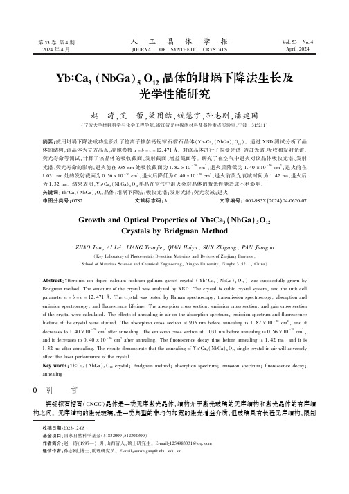
第53卷第4期2024年4月人㊀工㊀晶㊀体㊀学㊀报JOURNAL OF SYNTHETIC CRYSTALS Vol.53㊀No.4April,2024YbʒCa 3(NbGa )5O 12晶体的坩埚下降法生长及光学性能研究赵㊀涛,艾㊀蕾,梁团结,钱慧宇,孙志刚,潘建国(宁波大学材料科学与化学工程学院,浙江省光电探测材料及器件重点实验室,宁波㊀315211)摘要:使用坩埚下降法成功生长出了镱离子掺杂钙铌镓石榴石晶体(YbʒCa 3(NbGa)5O 12)㊂通过XRD 测试分析了晶体的结构,该晶体为立方晶系,晶胞参数a =b =c =12.471Å㊂对该晶体进行了拉曼光谱㊁透过光谱㊁吸收和发射光谱㊁荧光寿命等测试,计算了该晶体的吸收截面㊁发射截面㊁增益截面等㊂研究了在空气中退火对该晶体吸收光谱㊁发射光谱㊁荧光寿命的影响,退火前在935nm 处吸收截面为1.82ˑ10-20cm 2,退火后降低为1.40ˑ10-20cm 2,退火前在1031nm 处的发射截面为0.56ˑ10-20cm 2,退火后降低为0.40ˑ10-20cm 2,退火前荧光衰减时间为1.42ms,退火后为1.32ms㊂结果表明,YbʒCa 3(NbGa)5O 12单晶在空气中退火会对晶体的激光性能造成不利影响㊂关键词:YbʒCa 3(NbGa)5O 12晶体;坩埚下降法;吸收光谱;发射光谱;荧光衰减;退火中图分类号:O782㊀㊀文献标志码:A ㊀㊀文章编号:1000-985X (2024)04-0620-07Growth and Optical Properties of YbʒCa 3(NbGa )5O 12Crystals by Bridgman MethodZHAO Tao ,AI Lei ,LIANG Tuanjie ,QIAN Huiyu ,SUN Zhigang ,PAN Jianguo(Key Laboratory of Photoelectric Detection Materials and Devices of Zhejiang Province,School of Materials Science and Chemical Engineering,Ningbo University,Ningbo 315211,China)Abstract :Ytterbium ion doped calcium niobium gallium garnet crystal (Yb ʒCa 3(NbGa)5O 12)was successfully grown by Bridgman method.The structure of the crystal was analyzed by XRD.The crystal is cubic crystal system,and the unit cell parameter a =b =c =12.471Å.The crystal was tested by Raman spectroscopy,transmission spectroscopy,absorption and emission spectroscopy,and fluorescence lifetime.The absorption cross section,emission cross section,and gain cross section of the crystal were calculated.The effects of annealing in air on the absorption spectrum,emission spectrum and fluorescence lifetime of the crystal were studied.The absorption cross section at 935nm before annealing is 1.82ˑ10-20cm 2,and it decreases to 1.40ˑ10-20cm 2after annealing.The emission cross section at 1031nm before annealing is 0.56ˑ10-20cm 2,and it decreases to 0.40ˑ10-20cm 2after annealing.The fluorescence decay time before annealing is 1.42ms,and it is 1.32ms after annealing.The results demonstrate that the annealing of YbʒCa 3(NbGa)5O 12single crystal in air will adversely affect the laser performance of the crystal.Key words :YbʒCa 3(NbGa)5O 12crystal;Bridgman method;absorption spectrum;emission spectrum;fluorescence decay;annealing㊀㊀㊀收稿日期:2023-12-08㊀㊀基金项目:国家自然科学基金(51832009,512302300)㊀㊀作者简介:赵㊀涛(1997 ),男,山西省人,硕士研究生㊂E-mail:1254983331@ ㊀㊀通信作者:孙志刚,博士,助理研究员㊂E-mail:sunzhigang@0㊀引㊀㊀言钙铌镓石榴石(CNGG)晶体是一类无序激光晶体,结构介于激光玻璃的无序结构和激光晶体的有序结构之间㊂无序结构的激光玻璃,是一类典型的非均匀加宽的激光增益介质,但玻璃具有长程无序结构,限制㊀第4期赵㊀涛等:YbʒCa3(NbGa)5O12晶体的坩埚下降法生长及光学性能研究621㊀了声子的平均自由程,导致其热学性能相对较差,限制了高效㊁高功率密度激光的获得[1]㊂而传统的激光晶体如钇铝石榴石(YAG)晶体,具有很好的热学性质,但长程有序的特点使其具有相对单一的激活离子取代位置,导致其配位单一,激活离子的光谱较窄[2]㊂无序的钙铌镓石榴石晶体兼具两者的优点,具有光谱的非均匀加宽特性和较高的热导率,使得其在激光领域中具有潜在的应用价值㊂NdʒCNGG晶体的具有较宽的吸收与发射光谱,Pan等[3]采用直拉法生长了无序的NdʒCNGG晶体,InGaAs LD泵浦的峰值吸收截面约为4.1ˑ10-20cm2,在808nm LD激发的发射荧光谱中,4F3/2ң4I11/2的半峰全宽(full width at half maximum, FWHM)为15nm,4F3/2ң4I13/2半峰全宽为27nm,在超快激光脉冲产生方面展示出巨大的潜力㊂目前,研究人员对NdʒCNGG晶体的连续波㊁调Q及锁模超短脉冲激光特性已做了大量㊁系统的研究[4-6]㊂20世纪90年代初,随着体积小㊁效率高㊁寿命长的LD泵浦源的出现,Yb3+作为激光基质激活离子的研究迅猛发展㊂Yb3+具有最简单的能级结构,与Nd3+相比,具有本征量子缺陷低,辐射量子效率高,能级寿命长,吸收和发射光谱宽等特点㊂特别是Yb3+的吸收峰位于900~1000nm,能与目前商用的InGaAs半导体激光二极管泵浦源有效耦合,并且不需要严格控制温度㊂YbʒCa3(NbGa)5O12晶体(YbʒCNGG)已有相关报道,可获得连续激光输出,并通过锁模和调Q获得脉冲激光输出[7-9],证明了YbʒCNGG在激光领域的潜在价值㊂目前报道的YbʒCNGG晶体都是使用提拉法生长,该晶体的坩埚下降法生长还没有报道㊂坩埚下降法生长晶体是在密闭环境中进行,能有效防止原料Ga2O3的挥发;此外,与提拉炉相比较,坩埚下降炉价格低廉,设备维护简单,使用坩埚下降法生长晶体能够极大地降低生产成本,因此YbʒCNGG晶体可能更适合使用坩埚下降法生长㊂本文成功使用坩埚下降法生长出较大尺寸的YbʒCNGG晶体,并开展了其光学性能研究㊂1㊀实㊀㊀验1.1㊀原料制备和晶体生长YbʒCNGG晶体在1450ħ左右一致熔融,但在高温下Ga2O3原料会挥发,因此本实验采用坩埚下降法,在密闭环境中生长该晶体㊂使用的原料为Yb2O3(纯99.99%),CaCO3(纯99.99%),Nb2O5(纯99.99%), Ga2O3(纯99.999%),采用Ca3Nb1.6875Ga3.1875O12成分配比,按照以下的化学反应式进行多晶料的合成㊂2.892CaCO3+0.813375Nb2O5+1.626375Ga2O3+0.054Yb2O3=0.964Ca3Nb1.6875Ga3.1875O12㊃0.036Yb3Ga5O12+2.892CO2(1)按上述配比称量原料,进行充分研磨,放入混料机中混合24h,再进行液压机压块,随后放入马弗炉进行第一次烧结,烧结温度1000ħ,保温10h;取出后再次研磨㊁压块,进行第二次烧结,烧结温度1250ħ,保温时间30h,得到YbʒCNGG的多晶料㊂将多晶料放进装有YAG[111]籽晶的铂金坩埚,放入坩埚下降炉中进行晶体生长㊂接种温度为1450ħ,下降速度8mm/d㊂晶体生长结束后,以20ħ/h左右的速率使炉温降至室温,以消除晶体生长过程中所产生的热应力㊂众所周知,激光晶体在高温环境中工作一段时间后,性能会有所降低㊂在高温㊁富氧或贫氧环境中工作一段时间后某些单晶会改变颜色,导致其光学吸收带发生变化,这种现象已经在硅酸铋[10]㊁铌酸盐[11-12]㊁磷酸盐[13]和碱金属钼酸盐[14-16]等氧化物中发现㊂因此,本文在空气中对YbʒCNGG晶体进行了热退火,以此来探究高温环境工作后晶体的光学性能变化㊂将加工好的一块晶片切成两块,其中一块放进马弗炉中,在空气氛围下进行退火,退火温度为1000ħ,保温时间10h㊂1.2㊀性能测试使用德国Bruker XRD D8Advance型X射线粉末衍射仪对YbʒCNGG晶体的粉末样品进行XRD测试,辐射源为Cu靶X射线管,工作电压和电流分别为40kV和40mA,扫描范围10ʎ~70ʎ,步幅为0.02ʎ㊂使用DXR3Raman Microscope光谱仪记录了晶体在295K下的拉曼光谱,激发源为532nm波长的激光㊂使用美国Lambda950型紫外可见近红外分光光度计测量了晶体的吸收和透过光谱㊂使用法国FL3-111型荧光光谱仪测试了晶体的发射光谱,激发源为980nm激光㊂采用英国FLS980荧光光谱仪测试了晶体的荧光衰减曲线,激发波长980nm,监测波长1031nm㊂622㊀研究论文人工晶体学报㊀㊀㊀㊀㊀㊀第53卷2㊀结果与讨论2.1㊀晶体生长图1(a)为采用坩埚下降法生长得到的YbʒCNGG晶体,晶体直径为25mm,接种后生长部分长度约为80mm,其中偏析层部分约为25mm㊂晶体呈现咖啡色,透明,内部有少量裂纹,晶体开裂与晶体自身性质以及生长工艺有关㊂图1(b)为加工后的YbʒCNGG晶片,晶片直径25mm,厚度为1mm,属于(111)晶面,晶片中横向裂纹是加工所致㊂图1㊀坩埚下降法生长的YbʒCNGG晶体Fig.1㊀YbʒCNGG crystals grown by Bridgman method2.2㊀XRD分析图2为YbʒCNGG晶体单晶部分和顶部偏析层部分的粉末XRD图谱,将单晶部分的XRD数据导入Jade 中,通过拟合得出该晶体是Ia3d空间群,属于立方晶系,晶胞参数a=b=c=12.471Å,α=β=γ=90ʎ,比已报道的CNGG晶体晶胞参数(12.51Å)略小[17],原因是掺杂的Yb3+半径小于被取代的Ca2+半径,导致晶体晶格收缩㊂通过Jade分析,顶部偏析层的杂质成分大部分是立方焦火成岩(Ca2Nb2O7),这与文献[18]中得出结论一致,原因是掺入Yb3+后,生成了镱镓石榴石(Yb3Ga5O12),导致Ca2+与Nb5+的过量,从而生成了不属于石榴石相的Ca2Nb2O7㊂2.3㊀拉曼光谱图3是室温下YbʒCNGG退火前后晶体样品的拉曼图谱对比,孤立金属氧四面体基团[MO4](M代表Ga 和Nb)在700~900cm-1存在对称伸缩振动,这些[MO4]基团是石榴石晶格的结构单元,M阳离子进入到石榴石结构的d位[19]㊂在700~900cm-1看到两个密集的振动峰C1和C3,分别是[GaO4]和[NbO4]基团群的对称伸缩振动造成的,C1和C2峰下降明显,C3和C4变化较小的可能原因是晶体中部分Ga3+挥发,改变了晶体的结构和振动特性,影响了振动模式的活性㊂Ga3+挥发会对晶体中[GaO4]基团的对称伸缩振动产生影响㊂通常情况下,Ga O键连接可能会中断或减弱,这种情况可能导致对称伸缩振动变弱,在拉曼光谱中可能会表现为C1和C2峰强度下降㊂C2和C4分别是C1和C3的伴峰,此处出现峰,则代表[GaO4]和[NbO4]附近出现阳离子空位,峰强度越高,则代表阳离子空位浓度越高㊂从图中可以看出,退火后C2和C4处都出现了微弱的伴峰,表明在退火后的晶体中,阳离子空位浓度增加了,主要原因是高温退火后晶体表面的Ga3+浓度降低,但是幅度较小[20]㊂2.4㊀透过和吸收光谱退火前后晶体样品的透过图谱如图4(a)所示,600~2500nm的整体透过率接近80%,说明晶体质量较高,退火后晶体颜色变化不明显㊂图4(b)是YbʒCNGG晶体的吸收截面图,吸收峰对应Yb3+的2F7/2(基态)ң2F5/2(激发态)跃迁㊂基态2F7/2和激发态2F5/2分别被晶体场劈裂为4个和3个Stark能级,从基态多重态的几个Stark能级到激发态多重态2F7/2(0㊁1㊁2㊁3)ң2F5/2(0ᶄ㊁1ᶄ㊁2ᶄ)的电子跃迁大多数是声子辅助的,从而产生了相当宽的谱带㊂晶体退火前在935nm处吸收截面为1.82ˑ10-20cm2,退火后为1.40ˑ10-20cm2;退火前在971nm处吸收截面为1.22ˑ10-20cm2,退火后为1.03ˑ10-20cm2,退火后吸收截面明显降低㊂此外,㊀第4期赵㊀涛等:YbʒCa 3(NbGa)5O 12晶体的坩埚下降法生长及光学性能研究623㊀从图4(c)和4(d)可以计算得出,晶体退火前在935nm 处FWHM 为47.46nm,退火后为44.60nm;退火前在971nm 处FWHM 为23.47nm,退火后为23.86nm㊂退火后在935nm 处的FWHM 比退火前小了2.86nm㊂图2㊀YbʒCNGG 晶体中部单晶部分及顶部偏析层部分的粉末XRD 图谱Fig.2㊀Powder XRD patterns of the middle single crystal part and the top segregation layer of YbʒCNGGcrystal 图3㊀室温下退火前后YbʒCNGG 晶体样品的拉曼图谱Fig.3㊀Raman spectra of YbʒCNGG crystal samples before and post annealing at roomtemperature图4㊀室温下退火前后YbʒCNGG 晶体样品的性能测试㊂(a)透过光谱;(b)吸收光谱;(c)退火前晶体样品吸收光谱的高斯拟合图;(d)退火后晶体样品吸收光谱的高斯拟合图Fig.4㊀Performance testing of YbʒCNGG crystal samples before and post annealing at room temperature.(a)Transmission spectra;(b)absorption spectra;(c)Gaussian fitting of absorption spectra of crystal sample before annealing;(d)Gaussian fitting of the absorption spectrum of crystal sample post annealing 2.5㊀发射光谱关于YbʒCNGG 晶体的发射截面σem (λ)计算,本文使用互易法(reciprocity method),用下列公式进行计算㊂624㊀研究论文人工晶体学报㊀㊀㊀㊀㊀㊀第53卷σem (λ)=σαbsZ l Z u exp E zl -hc λkT ()(2)式中:σabs 为吸收截面,h 为普朗克常数,k 为玻耳兹曼常数,c 为光速,λ为波长,T 为实验温度,Z l /Z u 为下㊁上能级的配分函数比,E zl 为零声子线㊂如图5(a)所示,计算得出退火前975nm 处的发射截面为1.28ˑ10-20cm 2,退火后为1.11ˑ10-20cm 2,退火前1031nm 处的发射截面为0.56ˑ10-20cm 2,退火后为0.40ˑ10-20cm 2㊂退火后975㊁1031nm 处的发射截面均低于退火前㊂图5(b)是在980nm 激光激发下得到的发射光谱,发射峰位于1031nm 处,在相同测试条件下,退火后该晶体的发射强度明显低于退火前,这与计算得出的结果相一致,表明YbʒCNGG 晶体在空气中退火后,对其激光性能有不利影响㊂原因是空气中的高温退火可能会对材料的物理和化学性质产生影响,包括晶格结构的变化和缺陷的生成㊂退火过程中晶格结构的变化和缺陷的形成可能对透过谱和发射谱性能产生影响㊂晶格结构变化:高温退火可能引起晶格结构的重新排列㊂在退火过程中,原子或分子在晶体中重新定位以达到更低的能量状态㊂这可能导致晶格略微变化,晶格参数可能发生微小的变化,如晶胞参数㊁晶体取向等㊂这种微小的结构变化可能会影响透过谱和发射谱的特性㊂缺陷的生成:高温退火也可能导致缺陷的生成㊂例如,点缺陷(Ga 3+的挥发)㊁位错或晶界等缺陷的产生㊂这些缺陷可能导致电子状态的变化㊁局部晶格畸变或者在晶体中引入能级㊂这些缺陷可能会影响材料的光学性质,包括透过谱和发射谱㊂图5㊀室温下退火前后YbʒCNGG 晶体样品的发射截面曲线(a)和980nm 激光激发下得到的发射光谱(b)Fig.5㊀Emission cross-section curves (a)and emission spectra at 980nm excitation (b)of YbʒCNGG crystal samples before and post annealing at room temperature2.6㊀增益截面根据上述吸收和发射截面光谱,增益截面σg (λ)可由下式计算:σg (λ)=βσem (λ)-(1-β)σabs (λ)(3)式中:β为激发态离子反转分数㊂图6所示为退火前后的YbʒCNGG 晶体样品在不同β值(0,0.25,0.50,0.75,1.00)下的增益截面曲线㊂如图6(a)所示,在1010~1040nm 处,当布居反转分数达到25%时,增益截面变为正值㊂如此低的反转比例意味着1031nm 波长的YbʒCNGG 激光器将具有较低的泵浦阈值,这表明YbʒCNGG 晶体是1031nm 激光器的理想候选材料㊂在高抽运情况下,增益截面谱也较宽,表现出良好的可协调性㊂而退火后该晶体增益截面曲线如图6(b)所示,并且在布居反转比例达到50%时,在1031nm 附近的增益带宽明显低于退火前,因此理论上通过被动锁模达到最小脉冲也将会受到影响[21],也就是说,在高温下工作会对该晶体超快激光的产生造成不利影响㊂2.7㊀荧光衰减室温下对退火前后的YbʒCNGG 晶体样品进行荧光衰减测试㊂如图7所示,激发波长980nm,监测波长1031nm,采用单指数函数拟合,如公式(4)所示㊂y =A 1e -x t +y 0(4)㊀第4期赵㊀涛等:YbʒCa3(NbGa)5O12晶体的坩埚下降法生长及光学性能研究625㊀式中:A1为前因子,y0为初始强度,t为时间,x㊁y为测试的横纵坐标,对应波长㊁强度㊂通过拟合得到退火前的荧光衰减时间为1.42ms,退火后的荧光衰减时间为1.32ms,观察到退火后Yb3+的寿命减少,表明这种退火在晶体中引入了进一步的缺陷,很可能是由表面Ga3+的挥发造成的,与文献中采用提拉法生长的YbʒCNGG晶体τ=816μs相比较,结果相差很大,可能是该晶体有很强的重吸收,造成直接测量荧光寿命不准确,但是与文献中退火后Yb3+的寿命会减少的结论是一致的[20]㊂图6㊀室温下退火前后YbʒCNGG晶体样品增益截面曲线Fig.6㊀YbʒCNGG crystal samples gain cross-section curves before and post annealing at room temperature图7㊀室温下退火前后YbʒCNGG晶体样品荧光衰减曲线Fig.7㊀YbʒCNGG crystal samples fluorescence decay curves before and post annealing at room temperature3㊀结㊀㊀论采用坩埚下降法,生长出尺寸为ϕ25mmˑ80mm的YbʒCNGG透明单晶,通过XRD粉末衍射,得出了偏析层的主要杂质成分为Ca2Nb2O7㊂通过透过和吸收光谱得出该晶体退火前在935和971nm处有很宽的吸收带宽,分别为47.46和23.47nm,退火后935nm处吸收带宽变窄㊂尽管常规情况下退火有助于提高晶体的均匀性和激光性能,但在本文中通过对YbʒCNGG晶体退火前后晶体发射截面和增益截面的计算,以及发射光谱和荧光衰减的测量,发现采用高温退火可能会引入缺陷并导致激光性能下降㊂这可能暗示着退火温度需要重新评估或者退火周期需要调整以更好地维持晶体性能,后续本团队会继续研究不同退火条件对YbʒCNGG晶体激光性能的影响㊂参考文献[1]㊀于浩海,潘忠奔,张怀金,等.无序激光晶体及其超快激光研究进展[J].人工晶体学报,2021,50(4):648-668+583.YU H H,PAN Z B,ZHANG H J,et al.Development of disordered laser crystals and their ultrafast lasers[J].Journal of Synthetic Crystals, 2021,50(4):648-668+583(in Chinese).[2]㊀KANCHANAVALEERAT E,COCHET-MUCHY D,KOKTA M,et al.Crystal growth of high doped NdʒYAG[J].Optical Materials,2004,26626㊀研究论文人工晶体学报㊀㊀㊀㊀㊀㊀第53卷(4):337-341.[3]㊀PAN H,PAN Z B,CHU H W,et al.GaAs Q-switched NdʒCNGG lasers:operating at4F3/2ң2I11/2and4F3/2ң2I13/2transitions[J].OpticsExpress,2019,27(11):15426-15432.[4]㊀SHI Z B,FANG X,ZHANG H J,et al.Continuous-wave laser operation at1.33μm of NdʒCNGG and NdʒCLNGG crystals[J].Laser PhysicsLetters,2008,5(3):177-180.[5]㊀LI Q N,FENG B H,ZHANG D X,et al.Q-switched935nm NdʒCNGG laser[J].Applied Optics,2009,48(10):1898-1903.[6]㊀XIE G Q,TANG D Y,LUO H,et al.Dual-wavelength synchronously mode-locked NdʒCNGG laser[J].Optics Letters,2008,33(16):1872.[7]㊀SCHMIDT A,GRIEBNER U,ZHANG H J,et al.Passive mode-locking of the YbʒCNGG laser[J].Optics Communications,2010,283(4):567-569.[8]㊀LIU J H,WAN Y,ZHOU Z C,et parative study on the laser performance of two Yb-doped disordered garnet crystals:YbʒCNGG andYbʒCLNGG[J].Applied Physics B,2012,109(2):183-188.[9]㊀SI W,MA Y J,WANG L S,et al.Acousto-optically Q-switched operation of YbʒCNGG disordered crystal laser[J].Chinese Physics Letters,2017,34(12):124201.[10]㊀COYA C,FIERRO J L G,ZALDO C.Thermal reduction of sillenite and eulite single crystals[J].Journal of Physics and Chemistry of Solids,1997,58(9):1461-1467.[11]㊀ZALDO C,MARTIN M J,COYA C,et al.Optical properties of MgNb2O6single crystals:a comparison with LiNbO3[J].Journal of Physics:Condensed Matter,1995,7(11):2249-2257.[12]㊀GARCÍA-CABAES A,SANZ-GARCÍA J A,CABRERA J M,et al.Influence of stoichiometry on defect-related phenomena in LiNbO3[J].Physical Review B,Condensed Matter,1988,37(11):6085-6091.[13]㊀MARTÍN M J,BRAVO D,SOLÉR,et al.Thermal reduction of KTiOPO4single crystals[J].Journal of Applied Physics,1994,76(11):7510-7518.[14]㊀SCHMIDT A,RIVIER S,PETROV V,et al.Continuous-wave tunable and femtosecond mode-locked laser operation of YbʒNaY(MoO4)2[J].JOSA B,2008,25(8):1341-1349.[15]㊀MÉNDEZ-BLAS A,RICO M,VOLKOV V,et al.Optical spectroscopy of Pr3+in M+Bi(XO4)2,M+=Li or Na and X=W or Mo,locallydisordered single crystals[J].Journal of Physics:Condensed Matter,2004,16(12):2139-2160.[16]㊀VOLKOV V,RICO M,MÉNDEZ-BLAS A,et al.Preparation and properties of disordered NaBi(X O4)2,X=W or Mo,crystals doped with rareearths[J].Journal of Physics and Chemistry of Solids,2002,63(1):95-105.[17]㊀SHIMAMURA K,TIMOSHECHKIN M,SASAKI T,et al.Growth and characterization of calcium niobium gallium garnet(CNGG)singlecrystals for laser applications[J].Journal of Crystal Growth,1993,128(1/2/3/4):1021-1024.[18]㊀CASTELLANO-HERNÁNDEZ E,SERRANO M D,JIMÉNEZ RIOBÓO R J,et al.Na modification of lanthanide doped Ca3Nb1.5Ga3.5O12-typelaser garnets:Czochralski crystal growth and characterization[J].Crystal Growth&Design,2016,16(3):1480-1491.[19]㊀VORONKO Y K,SOBOL A A,KARASIK A Y,et al.Calcium niobium gallium and calcium lithium niobium gallium garnets doped with rareearth ions-effective laser media[J].Optical Materials,2002,20(3):197-209.[20]㊀ÁLVAREZ-PÉREZ J O,CANO-TORRES J M,RUIZ A,et al.A roadmap for laser optimization of YbʒCa3(NbGa)5O12-CNGG-type singlecrystal garnets[J].Journal of Materials Chemistry C,2021,9(13):4628-4642.[21]㊀SU L B,XU J,XUE Y H,et al.Low-threshold diode-pumped Yb3+,Na+ʒCaF2self-Q-switched laser[J].Optics Express,2005,13(15):5635-5640.。
纤维缠绕复合材料环形容器设计优化_英文_
Optim al Design of Filam ent2W ou nd C omposite T oroidsLei Zu,Sotiris K oussios,Adriaan Beukers Design and Production of Composite St ruct ures,Faculty of Aerospace EngineeringDelft University of Technology,Kluyverweg1,2629HS Delft,The Net herlandsAbstract:Composite toroids have emerged as an attractive alternative in many indust rial fields where space2saving,weight reduction and non2drift of center of mass are required.This paper aims to deter2 mine t he optimal winding t rajectories for geodesically overwound toroidal p ressure vessels,and to dem2 onst rate t he favorable performance of t he p resent design met hod.Wit h t he aid of t he continuum t heo2 ry and t he geodesic winding law,t he equations t hat determine t he required winding t rajectories on to2 rus are derived.The general criteria for avoiding fiber bridging on a torus are formulated,based on differential geo met ry.Next,t he initial winding angle and t he t hickness at t he equator are considered as t he design variables,while t he minimum struct ural mass act s as t he objective f unction.The optimal geodesic t rajectories,corresponding to various relative bending radii,are determined to evaluate t he effect on t he struct ural performance of toroids.The st ress field is modeled using classical lamination t heory and t he Tsai2Wu tensor t heory is employed as t he failure criterion for an individual layer.Re2 sult s show t hat t he optimization algorit hm is efficient and convergent to stable solutions while t he op2 timal winding pat h obtained does satisfy t he requirement s for t he manufact uring process.Result s also indicate t hat filament2wound toroids designed using t he p resent met hod show better performance, mainly t riggered by maximum utilization of t he laminate strengt h as compared to conventional geodes2 ics2based toroids.The recommended design2oriented met hod can easily be applied during preliminary dimensioning and optimization of filament2wound toroidal p ressure vessels.K ey w ords:Composite pressure vessels;Filament winding;Toroids;Geodesic winding;Classical lam2 ination t heoryDocument code:A Article ID:100124381(2009)Suppl220413207INTR OD UCTIONOptimal filamentary composite p ressure vessels p rovide significant advantages as co mpared to t heir steel2based counterpart s.The filament winding tech2 nique is widely used for t he manufact uring of FRP p roduct s.It is a p rocess by which continuo us reinfor2 cing fibers are p recisely positioned in a predetermined pattern on a rotating mandrel to form a clo sed shape. The process is normally CNC cont rolled to permit highly automated p roduction.Continuous fibers can be oriented to match t he directio n and magnit ude of st resses in a laminated struct ure,allowing optimal re2 inforcement loading.More recently,composite to2 roidal st ruct ures show great potential for applications in a variety of indust ries because of t heir st ruct ural efficiency,new2fashioned configuration,and low as2 pect ratio.The toroid belongs to t he class of doubly curved co mponent s,and is an interesting alternative for spaces having limited height.It can be regarded as a bent,endless cylinder t hat saves on t he need for material in t he end cap s.As a shape,it is t hus at least as st ruct urally efficient as a cylinder.So far, filament2wound convex bodies have been st udied for many years and t he design and p roduction of axisym2 met rically wound part s such as cylinders,sp heres and domes has became relatively simple and ma2 t ure[1-4].In winding anaxisymmet rically convex body,a basic fiber pat h is repeated continuously by indexing t he winding axis,opposed to a torus,which is a do ubly2clo sed body having a convex2concave sur2 face.Moreover,for high applied loads,toroidal p ressure vessels demand better struct ural efficiency314 Optimal Design of Filament-Wound Composite Toroidsand higher carrying capacity t han pipeline elbows[5,6] used in t he civilian indust ry.It is t hus desirable to employ a design2oriented met hod to determine t he op2 timal roving t rajectories satisfying requirement s for bot h t he struct ural optimization and t he winding p rocess.Several investigations have been conducted in winding toroidal st ruct ures,mainly based on t he net2 ting t heory and geodesic pat hs of which t he winding angles are in general rat her big.Zu et al.[7,8]p ro2 posed a design met hod for determining t he fiber pat hs and laminate configuration of filament2wound toroids using a two2level optimization approach.Chen[9] p resented t he calculatio n formulae to determine t he burst pressure of toroidal vessels wit h various types of winding.Yu et al.[10]outlined a winding pattern for geodesically overwound toroidal vessels and car2 ried out t he comp uter simulation for such pattern. Jiang et al.[11]developed a novel winder for produ2 cing toroidal p ressure vessels,based on t he design of t he machine configuratio n.K oussios[12]and Zu[13] p resented t he cro ss2sectional shapes of isotensoid to2 roids andcompared t he st ruct ural efficiency of such toroids wit h t he circular ones.However,p revious st udies have failed to consider t he optimal design of t he winding t rajectories based on t he co ntinuum t heo2 ry of ort hot ropic laminates.The met hod based on t he netting t heory has a major defect in t hat design calcu2 lations are based on fiber st rengt h alone,and t he ma2 t rix effect is considered negligible.In addition,de2 spite t he fact t hat toroidal vessels,which are gov2 erned by t he condition of equal shell st rains or,in ot her words,zero shear st ress at lamina level,do show great performance,t he rigorous f riction coeffi2 cient s required during t he winding p rocess is certainly limiting t he available design space[7].A typical ex2 ample of t his rest riction is t he limit for t he smaller relative bending radius a toroidal vessel can o btain. Geodesics show great stability on a curved surface and are entirely determined by t he initial winding an2 gle.The laminate parameters such as t he winding an2 gle and t he shell t hickness must t hus be caref ully cho sen to achieve a maximum st ruct ural efficiency of toroids.In t his paper we o utline a design2oriented met hod for determining t he optimal geodesic t rajecto2 ries for filament2wound toroids under uniformly in2ternal p ressure.Firstly we present t he geodesic equa2 tions for determining fiber trajectories on t he torus. Then,wit h t he aid of classical lamination t heory and t he geodesic law,t he optimal design for geodesically overwound toroids is presented to obtain t he roving pat hs,while taking t he t hickness build2up of t he wound layers into account.The influence of t he rela2 tive bending radii on t he geomet ry of t he optimal geo2 desic pat hs is also stly,t he calculations and comparisons of st ruct ural mass and on2axis stress of laminate shell designed using optimal geodesic winding and conventional geodesic winding are car2 ried out to show t hat optimal geodesic pat hs form a p referable alternative for t he design of filament2 wound toroidal vessels.1 G eodesics on a torusA toroidal vessel is a generic shell of revolution wit h circle areas surrounding t he rotation axis defined as Z2axis,see Fig11.A toroidal shell has a bending radius R and a radius of t he t ube r.It is a complete shell,extending t hrough360°in t he meridional(φ) and parallel(θ)directions.Thevector representation of a torus can be exp ressed as S(θ,φ): S(θ,φ)=(R+r cosφ)cosθ(R+r cosφ)sinθ r sinφ(1)whereθandφstand for t he angular coordinates in t he parallel and meridional directions of t hetorus respec2 tively,as shown in Fig11.Fig11 Shape of a torus and fiber pat hThe slippage coefficientλrepresent s t he tenden2 cy of slippage of t he placed roving bundles on t he supporting surface,which is defined as t he ratio of414 材料工程/2009年增刊2(SAMPE China2009) t he geodesic curvat ure ,k g ,to t he normal curvat ure ,k n[14]:λ=k g /k n (2)For λ=0t he solution of Eq.(2)is t he geodesic equation.In every ot her case (λ≠0),t he roving 2pat h will deviate f rom t he geodesic and is t herefore renamed as non 2geodesic.From Eq.(1),t he firstf undamental form of S (θ,φ)can be obtained by dif 2ferential geomet ry :E =(R +r cos φ)2, F =0, G =r 2(3)Eq.(3)is only valid for cases where t he main curvat ure directions are perpendicular to each ot her.This conditio n does apply on shells of toroids.Sub 2stit ution of Eq.(3)into t he Liouville formula [15]leads to t he exp ression for k g :k g =d αd l +sin φR +r cos φco sα(4)where αis t he angle between t he roving pat h and t he meridio nal direction of t he dome ,i.e.,t hewinding angle ,as shown in Fig 11;l is t he roving lengt h.For k g =0,t he differential equation of geodesics on a torus becomes :d αd l =-sin φR +r co sφco sα(5)Since t he fiber curve has an orientation αwit h respect to t he parallel circle of t he torus ,t herelationamong geomet ric parameters d θ/d l ,d φ/d l and α,can be givenby (Fig 12):d θd l =cos αR +r co s φ, d φd l =sinαr(6)Fig 12 Geometrical parameters θ,φ,l and αSubstit ution of Eq.(6)into (5)leads to :d αd φ=r sin φ(R +r co s φ)tg α(7)d θd φ=r(R +r co s φ)tg α(8)Integrating Eq.(7)leads to t he paramet ric geo 2desic equation :(R +r co s φ)cos α=C(9)where C is a co nstant value determined by initial winding angle α0.By integrating Eq.(8)f romt he known angular coordinates of t he starting point ,t he t urn 2around angle θcan be calculated atany point a 2long t he fiber pat h.It is apparent that t he geodesic pat h extends periodically on a torusand is completely determined by initial winding conditions.Fig 13shows a geodesic pat h for t hefirst winding cycle on atorus.Fig 13 One 2cycle geodesic line on a torus2 Optimal design for minimum structural massIn this section ,we address the problem of searching the minimum mass of laminated structurefor internally pressurized toroidal vessels.The initial winding angle α0and laminate thickness t 0at the equator are considered as the design variables ,as stated by :X =(α0,t 0)211 Objective FunctionThe laminate mass of a toroidal shell is suppo sed to be t he objective f unction of t he optimal design p roblem ,given by :M =2πr γ(R +r )sin α0t 0∫2πcsc αdφ(10)where γis t he density of t he used composite lami 2nate ,αis a f unction of meridional coordinate φ,whichis given by Eq.(9).To simplify t he mat hematical modeling and com 2p utation ,t he following dimensionless variables areint roduced :K =Rr ,M =M ・Y T 2γpπr 3,t =t ・2Y T p r (11)where K is t he so 2called relative bending radius ,p is514 Optimal Design of Filament -Wound Composite Toroidst he uniformly internal p ressure,and YT is t hetensile st rengt h t ransverse to fibers.Substit uting Eq.(11)into(10),t he dimension2 less mass of a toroid can be given by:M=(K+1)sinα0t0∫2π0cscαdφ(12) 212 Stable Criteria for roving trajectoriesThe torus is not always convex,t herefore t he winding roving may bridge and may not cover t he to2 rus unless t he normal curvat ure kn meet s t he follow2 ing requirement[14]:k n<0(13) k n can be exp ressed in terms of t he main curva2 t ures in t he meridional and parallel directions.Ac2 cording to t he Euler formula[15],we obtain:k n=-cosφR+r co sφcos2α-1rsin2α(14)From Eq.(14),it is impossible to create fiber2 bridging on t he convex part of a torus since wehave t he permanent result of k n<0.However,for t he sat2 isfaction of condition Eq.(13),t he winding angleαon t he concave part should satisfy t he inequality as follows:-co sφK+cosφ-t g2α<0(15) 213 Strength Constraints2.3.1 Elastic relationshipThe internal resultant forces of t he toroidal shell are evaluated using t he membrane t heory.From t he static equilibrium equations of t he shell element un2 der internal p ressure p,t he internal resultant forces in geometric coordinates are given by[16]:Nφ=p r2・2K+cosφK+co sφ, Nθ=p r2(16)where subscript sφandθindicate t he meridional and parallel directions,respectively.The shell is assumed to consist of helically wound layers,each of which forms an angle2ply con2 figuration co nsisting of±αlayers,as shown in Fig14.The stress component s referred to t he materi2 al axes in an individual layer are given by:σ1=1t(m11Nφ+m12Nθ)σ2=1t(m21Nφ+m22Nθ)τ12=1t(m31Nφ+m32Nθ)(17)Fig14 A symmetric laminate under in2planeloads(Nφ,Nθ)where constant s m ij are f unctions of t he ply angle andmaterial properties,given by: m11=c2+2cs Q22Q16-Q12Q26Q11Q22-Q212, m12=s2+2cs Q11Q26-Q12Q16Q11Q22-Q212, m21=s2-2cs Q22Q16-Q12Q26Q11Q22-Q212, m22=c2-2cs Q11Q26-Q12Q16Q11Q22-Q212, m31=-sc+(c2-s2)Q22Q16-Q12Q26Q11Q22-Q212, m32=sc+(c2-s2)Q11Q26-Q12Q16Q11Q22-Q212.(18)where c=sinα,s=co sαandαis t he winding angle offiber pat h.Q ij are t he component s of t hereducedstiff ness mat rix,which are related to t he laminatestiff ness mat rix[Q]:Q11=Q11c4+2(Q12+2Q66)c2s2+Q22s4Q12=(Q11+Q12-4Q66)c2s2+Q12(c4+s4)Q22=Q11s4+2(Q12+2Q66)c2s2+Q22c4Q16=-Q22cs3+Q11c3s-(Q12+2Q66)(c2-s2)csQ26=-Q22c3s+Q11cs3+(Q12+2Q66)(c2-s2)csQ66=(Q11+Q12-2Q12)c2s2+Q66(c2-s2)2(19)in which t he component s of t he laminate stiff ness ma2t rix[Q]appearing in Eq.(19)are stated as:Q11=E11-ν12ν21,Q22=E21-ν12ν21,Q12=ν12E21-ν12ν21,Q66=G12(20)where E1,E2,G12andν12are t he elastic modulus int he longit udinal and t ransverse directions,t heshearmodulus and major Poisson ratios of a unidirectionallayer.2.3.2 Failure criterionThe failure load is determined by employing a614 材料工程/2009年增刊2(SAMPE China2009) failure criterion.In t his st udy,t he Tsai2Wufailure criterion[17]is used which stip ulates for non2failure const raint:F iσi+F ijσiσj≤1 (i,j=1,2,6)(21) i n w hich t he st ren gt h p arameters F11,F22,F12,F66, F1,F2and F6are gi ven by: F11=1X T X C , F22=1Y T Y C, F66=1S2,F12=-12X T X C Y T Y C, F1=1X T-1X C, F2=1Y T -1Y C,F6=0(22)where X T,X C,Y T,and Y C are t he tensile and com2 pressive st rengt hs of t he unidirectional layer int he fi2 ber and t ransverse directions,and S is t he in2plane shear failure st rengt h.214 Optimization ProcedureIn t his paper,t he design problem involves mini2 mizing t he st ruct ural mass M,subjected to t he con2 straint equations(15)and(21).This design refers to t he nonlinear const rained optimization problem. The SQ P(sequential quadratic p rogramming)met h2 od is here employed to solve t he optimization p rob2 lem.Since t he number of rovings passing t hrough t he cro ss section of a slice of t he torus at any meridional location is constant,t he t hickness dist ribution can be expressed as a f unction of t he meridional coordinateφas follows[18]:t=(K+1)sinα0(K+cosφ)sinα・t0(23)When a winding t rajectory t hat satisfies t he con2 straint conditions,is assigned as a set of design varia2 bles in t he i th iteration step of optimization p roce2 dure,t he t hickness dist ribution of t he shellis deter2 mined by Eq.(23)and t hen t he values of t he exp res2 sion on t he left2hand side of t he constrained equations (15)and(21)are evaluated at t he point s along t he geodesic pat h.At each iteration step,t he point s used for t he evaluation are determined by solving t he geo2 desic equations of roving t rajectories.The objective mass M is calculated using Gaussian quadrat ure rule at each iteration step.The current design point is up dated as a new point by t his p rocedure.The above step s are repeated until a termination criterion is sat2 isfied.3 RESU L TS AN D DISCUSSIONThe optimization process of t he toroidal pressure vessel is carried out by considering a collection of tori wit h various relative bending radii K.The laminate is made of T300/5208grap hite/epoxy t he elastic con2 stant s of which are E1=142GPa,E2=1018GPa,G12 =5149GPa andν12=013.The st rengt h values are X T =1568M Pa,Y T=57M Pa,X C=1341M Pa,Y C= 212M Pa,and S=80M Pa.The values for t he material p roperties are obtained f rom Ref.[19].Fig15illust rates t he winding angle develop ment s of t he optimal fiber pat hs along t he meridional coor2 dinateφ.The result s show t hat t he winding angle determined using t he p resent met hod is smaller t han t he one determined using conventional geodesic wind2 ing met hod,of which t he initial angle is always about 70°or even bigger.Therefore,t he optimal winding pat h maximizes t he utilization of tensile st rengt h of rovings.The optimal winding angle decreases from t he maximum value at t he outer ring to t he minimum value at t he inner ring,and shows smoot h variation for t he bigger relative bending radius.In addition, t he fiber pat h entirely meet s t he non2bridging condi2 tion as given in Eq.(15).The simulation of optimal roving trajectories determined using t he p resent met hod is depicted in Fig16.It is illust rated t hat t he windingpatternsatisfies t he mat hematical p rinciples of winding torus.Fig15 Winding angles development s using t he present met hod714 Optimal Design of Filament-Wound Composite ToroidsFig 16 Roving trajectories determined using t he present met hodFig 17 shows t he dist ributions of laminatest resses referred to material coordinates for toroidsobtained using t he present met hod and t he conven 2tional geodesic winding met hod.The result s show t hat t he laminate shell determined using t he p resent met hod p roduces higher stresses t han t he one using conventional geodesic winding ,while t he Tsai 2Wu criterion is satisfied t hroughout t he whole st ruct ure.Therefore ,t he laminate st rengt h of t he resulting to 2roidal vessels can be maximally utilized by t he p res 2ent met hod.Additio nally ,result s indicate t hat t he σT is relatively high and t hat st ruct ural failure is always governed by t he t ransverse st ress at t he region near t he outerring.Fig 17 On 2axis stress distributions obtained using t he present met hod and conventional met hod Table 1list s t he optimal values of initial windingangles and dimensionless masses of t hepresent to 2roids corresponding to t he relative bending radii ran 2ging fro m 3to 8,compared wit h t hemasses of con 2ventional geodesic winding toroids (α0=70°).Results show t hat t he p resent toroid isconsistently lighter t han t he one relying on t he conventional geodesic winding.It is revealed thatthe filament 2wound toroids designed using the present optimal design method has betterperformance and higher carrying capacity.Table 1 Optimal values of dimensionless masses and initial winding anglesRelative bendingRadiusK =3K =4K =5K =6K =7K =8Mass for conventionalgeodesic pat h (α0=70°)9.54311.39213.38515.42317.47919.545Mass for optimal geodesic pat h 8.4237.6847.7867.9988.2968.656Initial Winding Angle65.90561.84960.43459.42558.68758.1244 CONC L USIONSThe main goal of t his paper is to p rovide t he op 2timal design met hod for t he determination of roving t rajectories and laminate t hicknesses for filament 2wound toroidal pressure vessels ,and to evaluate t he effect of t he optimal winding pat hs on t he geomet ryand performance of toroids.An optimization proce 2dure which aims to minimize t he struct ural mass of p ressure vessels is outlined based on t he continuum t heory ,stability 2ensuring winding conditions and t he Tsai 2Wu failure criterion.The classical lamination t heory is employed for t he st ress analysis and t he SQ P met hod is used as a non 2linear optimizatio n algo 2rit hm.Moreover ,t he met hod p ropo sed here is based814 材料工程/2009年增刊2(SAMPE China 2009) on geodesic trajectories and t herefore is very usable for p ressure vessels manufact uring.As a result of t he optimal design procedure,t he winding angle of t he optimal pat h is decreased along t he meridional direc2 tion from t he outer parallel ring to t he inner parallel ring,and is smaller t han t hat obtained by conven2 tional geodesic winding.The optimizatio n procedure is well convergent to stable solutions while t he opti2 mal roving pat h does satisfy all t he design con2 straint pared wit h t he conventional geodesic pat hs,t he result s also demonst rate t hat t he winding pat h determined using t he present met hod maximizes t he utilization of laminate strengt h and t hus minimi2 zes t he mass of t he toroid.In conclusion,t he st ruc2 t ural performance of toroidal pressure vessels can be remarkably imp roved using t he p resent design met h2 od.The outlined t rajectories and t he optimization met hod are very co nvenient for t he design and pro2 duction of composite toroidal vessels.The present met hodology can only be considered as an app roach of optimal design based on geodesic winding.Since t he geodesic pat h is entirely deter2 mined by t he underlying meridian profile and initial winding angle,t heir geomet ry combined wit h t he re2 quirement s for t he winding process certainly limit s t he improvement of t he st ruct ural performance.It is t herefore desirable to exploit f riction2based non2geo2 desics to enlarge t he design space of filament2wound toroids and determine t he most efficient winding pat hs for such st ruct ures.Additionally,t he reinfor2 cing layers at t he part of t he outer circle will also be considered in order to avoid t he premat ure failure by t he t ransverse failure.However,it is believed t hat t he present met hod could p rove to be very usef ul in t he design stage of a compo site toroidal pressure ves2 sel.References[1] K oussios S,Bergsma O K and Beukers A.“Filament WindingPart1:Determination of t he Wound Body Related Parameters,”Comp Part A:Appl Sci Manuf,2004;35(2):181-195.[2] K oussios S,Bergsma O K and Beukers A.“Filament WindingPart2:Generic K inematic Model and It s Solutions,”Comp PartA:Appl Sci Manuf,2004;35(2):197-212.[3] Park J S,Hong CS,K im CG and K im CU.“Analysis of FilamentWound Composite Structures Considering t he Change of WindingAngles Through t he Thickness Direction,”Compos Struct, 2002;55:33-71.[4] Velosa J C,Nunes J P,Antunes PJ,Silva J F and Marques A T.“Development of A New Generation of Filament Wound Compos2 ite Pressure Cylinders,”Compos Sci Technol,2009;69(9):1348-1353[5] Li H S,Liang Y D and Bao H J.“CAM system for filamentwinding on elbows,”J.Mater.Process.Technol.,2005;161(3):491-496.[6] Li H S,Liang Y D.“Computer aided filament winding for el2bows,”J.Software,2002;13(4):518-525.[7] Zu L,K oussios S,Beukers A.“Pattern design and optimizationfor filament wound toroidal pressure vessels”.Proc.23rd Annual Conference of t he American Society for Composites,Memphis, TN,September2008.[8] Zu L,He QX and Ni QQ.“Pattern Design for Non2geodesicWinding Toroidal Pressure Vessels,”Proceedings of t he16t h In2 ternational Conference on Composite Materials(ICCM/16),Kyoto,J apan,J uly2007.[9] Chen RX.“Design analysis on t he filament2wound toroidal pres2sure vessel,”Journal of Solid Rocket Technology,2006;29(6): 446-450.[10] Yu ZS,Yang ZT and Chu G L.“Design pattern and simulation oftorus for filament winding”,Mechanical and Electrical Engineer2 ing Magazine,2008;25(4):75-77.[11] Jiang XZ,Fei CD and Ma GF.“Filament Winding Process ofToroidal Vessels,”Fiber compos,2005;41(1):41-43.[12] K oussios S and Beukers A.“Composing Composites:A Para2digm of Reversed Design,”J.Design Research,5(3):302-316.[13] Zu L,K oussios S and Beukers A.“Design of Filament WoundToroidal Pressure Vessels wit h Circular and Isotensoid2based Cross Sections,”Journal of Material Engineering,2008;S1:78~86.[14] De Carvalho J,Lossie M,Vandepitte D and Van Brussel H.“Optimization of Filament Wound Part s Based on Non2geodesic Winding,”Compos Manuf,1995;6(2):79-84[15] Gray A.Modern Differential Geometry of Curves and Surfaces.Boca Ration:CRC press,1993.[16] Flügge W.Stresses in Shells.2nd ed.New Y ork:Springer,1973.[17] Tsai SW,Wu EM.“A general t heory of strengt h for anisotropicmaterials”.Journal of Composite Materials,1971;5:58-80. [18] Li S G,Cook J.“An analysis of filament overwound toroidalpressure vessels and optimum design of such structures”.Journal of Pressure Vessel Technology,2002;124(2):215-222. [19] Tsai,SW,Hahn H T.Introduction to composite Materials.Westport,Conn.:Technomic Publishing Company,Inc.,1980.作者简介:祖磊(1983—),男,博士,助理研究员,荷兰代尔夫特理工大学航空航天系。
The Optimal Isodual Lattice Quantizer in Three Dimensions
x · x dx
(1)
lattice has the largest packing radius and the smallest covering radius. The m.c.c. lattice, denoted here by M3 , has Gram matrix √ −1 −1 1+ 2 √ √ 1 −1 1+ 2 1− 2 2 √ √ −1 1− 2 1+ 2 determinant 1, packing radius
(3)
where α, β , h are any real numbers satisfying 0 ≤ 2h ≤ α ≤ β , αβ − h2 = 1. In the indecomposable case the nonzero conorms are: p01 = αβ 2α(1 − β ) α(2 − β ) , p02 = , p03 = , γ γ βγ 2β (1 − α) 2(1 − α)(1 − β ) β (2 − α) , p13 = , p23 = , αγ γ γ (4)
The Optimal Isodual Lattice Quantizer in Three Dimensions
J. H. Conway Mathematics Department Princeton University Princeton, NJ 08544 N. J. A. Sloane AT&T Shannon Labs 180 Park Avenue Florham Park, NJ 07932-0971 Email: conway@, njas@ Jan 02 2006. Abstract The mean-centered cuboidal (or m.c.c.) lattice is known to be the optimal packing and covering among all isodual three-dimensional lattices. In this note we show that it is also the best quantizer. It thus joins the isodual lattices Z, A2 and (presumably) D4 , E8 and the Leech lattice in being simultaneously optimal with respect to all three criteria. Keywords: quantizing, self-dual lattice, isodual lattice, f.c.c. lattice, b.c.c. lattice, m.c.c. lattice AMS 2000 Classification: 52C07 (11H55, 94A29)
- 1、下载文档前请自行甄别文档内容的完整性,平台不提供额外的编辑、内容补充、找答案等附加服务。
- 2、"仅部分预览"的文档,不可在线预览部分如存在完整性等问题,可反馈申请退款(可完整预览的文档不适用该条件!)。
- 3、如文档侵犯您的权益,请联系客服反馈,我们会尽快为您处理(人工客服工作时间:9:00-18:30)。
Technical ReportComputer Science DepartmentColorado State UniversityFort Collins,CO80523-1873Phone:(970)491-5792Fax:(970)491-2466WWW:Optimal Routing in Trivalent Cayley Graph NetworkPremkumar Vadapalli and Pradip K SrimaniDepartment of Computer ScienceColorado State UniversityFt.Collins,CO80523AbstractWe develop an optimal routing algorithm as well as establish the actual value of the diameter of the newly proposed trivalent Cayley network graphs in[VS95]1IntroductionFixed node degree networks constitute an important and essential component in designing any distributed system. Networks,in which degree of the nodes increases with the size of the network,are not suitable for applications in-volving large number of nodes[CAB93].Fixed node-degree networks are also needed from VLSI implementation point of view[SP89];there are applications where the computing nodes in the interconnection network can have only afixed number of I/O ports[CAB93].There are a few network graphs in the literature[PR82,LS82,PN93] where the node degree does not increase with network size;most popular among them are the De Bruijn graphs [PR82]or the Moebius graphs[LS82],but they are not regular and they are also not maximally fault tolerant. Very recently authors in[VS95]have proposed a new family of regular networks of degree3;it has been shown that the network has a has a logarithmic diameter in the number of nodes and has a vertex connectivity of3,i.e., the graphs are maximally fault tolerant(vertex connectivity cannot exceed the node degree).Although a simple routing algorithm was provided that gave an upper bound on the diameter of the network,optimal routing in the network was left as an open problem.Our purpose in the present paper is to develop an optimal routing algorithm as well as establish the exact value of the diameter of these trivalent Cayley network graphs.2Trivalent Cayley GraphIn this section,we briefly recall the construction of the trivalent Cayley graphs to facilitate our design of the optimal routing algorithm in the next section;details about the topological properties and fault tolerance of these graphs can be found in[VS95].is defined as a symmetric(undirected)graph on vertices for any integer,;each vertex corresponds to a circular permutation of symbols in lexicographic order where each symbol may be present ineither un complemented or complemented form.Let,denote the-th symbol in the set of symbols (we use English alphabets as symbols;thus for,,,and).We use to denote either or.Thus,for distinct symbols,there are exactly different cyclic permutation of the symbols in lexicographic order(disregarding the complements)and since each symbol can be present in either complemented or un complemented form,the vertex set of has a cardinality of.For example,for,the number of vertices in is;,,are valid nodes while or are not(since neither nor is a cyclic permutation of the three symbols in lexicographic order).Let denote the identity permutation.Since each node is some cyclic permutation of the symbols in lexicographic order,then if denotes the label of an arbitrary node and for some integer,then for all,,we have.The edges of are defined by the following three generators in the graph:Note that The three generators are closed under inverse;in particular is its own inverse()and is inverse of;thus the edges in are bidirectional.Also,For any,,the graph:(1)is a symmetric (undirected)regular graph of degree3;(2)has vertices;and(3)has edges.Figure1shows the trivalent Cayley graph of dimension3.3Diameter and Optimal RoutingSince is a Cayley graph[VS95],it is vertex symmetric[AK89],i.e.,we can always view the distance between any two arbitrary nodes as the distance between the source node and the identity permutation by suitably renaming the symbols representing the permutations.For example,let be the source node and be the destination node.We can map the destination node to the identity node by renaming the symbols as,, ,,and.Under this mapping the source node becomes.Then the paths between the original source and destination nodes become isomorphic to the paths between the node and the identity node in the renamed graph.Thus,in our subsequent discussion about a path from a source node to a destination node,the destination node is always assumed to be the identity node.Definition1Consider an arbitrary node in.There exists an unique integer such that.We define left distance and right distance of the node(from the identity node)as follows:=if=otherwise=if=otherwiseFigure1:Trivalent Cayley Graphwhere,for some p,for some pThen,we define the distance of the node(from the identity node)asRemarks:The symbol divides the node symbol sequence into two parts:and .The parameter indicates the number of complemented symbols in thefirst part and the parameter indicates the number of complemented symbols in the second part.The parameter indicates the length of the longest substring(s)of un complemented symbols in thefirst part.We use to indicate the left end of the leftmost of such substrings.If,then we set.The parameter indicates the length of the longest substring(s)of un complemented symbols in the second part.We use to indicate the left end of the leftmost of such substrings.If,then we set.Example1:Consider the node in(the identity node is).Here,,since ,(due to the substring“hij”),,(due to the substring“cd”),, (due to),(due to and),(we use the second formula as we do not have any complemented symbol to the right of the string corresponding to before“a”)and(we use the first formula as we have“”to the right of the string corresponding to).Hence.Theorem1For an arbitrary node in,,where and .Proof:We need to consider the case of each operator separately;assume with corresponding, ,,and.Case1:()We have,,and there can be four possible changes in and(note that either or or both can change at most by).Subcase A:&.We get and=;or.Subcase B:&.We get and;or.Subcase C:&.We get and;or.Subcase D:&.We get and;or.Case2:()We have and there can be four possible changes in,,and Subcase A:,,&.We get and;or.Subcase B:,,&.We get and;or.Subcase C:,,&.We get and(if we have the same formula for and;otherwise);or.Subcase D:,,&.We getand(if we have the same formula for and;otherwise);or.Case3:()We have and there can be four possible changes in,,and Subcase A:,,&.We get and;or.Subcase B:,,&.We get and;or.Subcase C:,,&.We get and(if we have the same formula for and;+otherwise);or.Subcase D:,,&.We getand(if we have the same formula for and;+otherwise);or.Corollary1For the identity node in,and for any,.Remark:Given an arbitrary node,the values of,,,and can be easily computed in linear time by scanning the node label once;while doing so,the values of and(refer definition1and the following remarks)corresponding to and respectively may also be stored as integer variables.In example 1above,the values of and are and respectively.Once this is done,,and can be computed according to definition1and the algorithm OptRout correctly generates an optimal(shortest) path of length D(s)from the node to the identity node.Proof:From the definition1and the construction of the algorithm,it is evident that the algorithm constructs a path of length for a given node.From theorem1,application of any one of the three operators and can decrement the value of of any node at best by one and since these are the only edges in the graph,the algorithm does generate the optimal path from the node to the destination node.Corollary2For an arbitrary node in,the function,given by definition1,correctly gives the distance of the node from the identity node.Corollary3For an arbitrary node in(),there exists a,such that .Proof:Obvious from theorem2.Theorem3The diameter of the graph is given byif is evenif is oddProcedure OptRout()Proof:To get the diameter,we must maximize the distance.Left distance and right distance are maximized by putting and,i.e.,Now,and.Hence to maximize the distance,we must minimize,i.e.when is even and when is odd.Under these circumstances,maximum possible value for the distance becomes when is even and when is odd.Consider the node.We see that,if is odd and, if is even.Thus,the result follows.4ConclusionWe have developed an optimal routing algorithm as well as determined the diameter of the trivalent Cayley graphs. Thus,these results further enhance the utility of those network graphs.References[AK89]S.B.Akers and B.Krishnamurthy.A group-theoretic model for symmetric interconnection networks.IEEE Transactions on Computers,38(4):555–566,April1989.[CAB93]C.Chen,D.P.Agrawal,and J.R.Burke.dBCube:a new class of hierarchical multiprocessor intercon-nection networks with area efficient layout.IEEE Transactions on Parallel and Distributed Systems, 4(12):1332–1344,December1993.[LS82]W.E.Leland and M.H.Solomon.Dense trivalent graphs for processor interconnection.IEEE Trans-actions on Computers,31(3):219–222,March1982.[PN93] D.J.Pritchard and D.A.Nicole.Cube connected M¨o bius ladders:an inherently deadlock freefixed degree network.IEEE Transactions on Parallel and Distributed Systems,4(1):111–117,January1993. [PR82] D.K.Pradhan and S.M.Reddy.A fault tolerant communication architecture for distributed systems.IEEE Transactions on Computers,C-31(9):863–870,September1982.[SP89]M.R.Samatham and D.K.Pradhan.The De Bruijn multiprocessor network:a versatile parallel pro-cessing and sorting network for VLSI.IEEE Transactions on Computers,38(4):567–581,April1989. [VS95]P.Vadapalli and P.K.Srimani.Trivalent Cayley graphs for interconnection rmation Processing Letters,54(6):329–335,June1995.。