2013-Microstructure evolution during tensile deformation of a nanostructured bainitic steel
电化学沉积英语
Electrochemical deposition (ECD), a versatile and widely employed surface modification technique, offers unparalleled precision and control in the creation of functional coatings, thin films, and nanostructured materials. This method involves the controlled reduction or oxidation of ions at an electrode surface under the influence of an applied electric field, resulting in the formation of a deposit with desired properties. To achieve high-quality and high-standard ECD processes, it is crucial to consider multiple factors, including the selection of appropriate electrolyte systems, electrode design, process parameters, and post-deposition treatments. This comprehensive analysis delves into these aspects, highlighting their significance and interplay in ensuring the successful execution of electrochemical deposition.1. **Electrolyte Systems: The Foundation of Electrochemical Deposition**The choice of electrolyte system plays a pivotal role in determining the quality and standard of the deposited material. An ideal electrolyte should:a. **Contain the desired metal ions**: The electrolyte must contain soluble salts or complexes of the metal to be deposited. The chemical stability, solubility, and redox potential of these ions directly influence the deposition rate, morphology, and composition of the film.b. **Provide suitable supporting electrolytes**: Supporting electrolytes, such as inorganic salts or organic additives, enhance ionic conductivity, stabilize the double layer, and minimize side reactions. They also influence the nucleation and growth kinetics of the deposit, affecting its microstructure and adhesion.c. **Include functional additives**: To tailor the properties of the deposited material, various functional additives can be incorporated into the electrolyte. These may include surfactants for modifying surface energy and controlling particle size, complexing agents for adjusting ion speciation, or inhibitors for suppressing unwanted reactions or impurity incorporation.2. **Electrode Design: The Interface of Electrochemistry and Deposition**The design and preparation of the substrate electrode significantly impactthe quality and standard of the deposited film. Key considerations include:a. **Substrate material**: The substrate material should possess adequate electrical conductivity, chemical compatibility with the electrolyte, and mechanical stability during the deposition process. Moreover, its surface chemistry and roughness can influence nucleation and adhesion of the deposited layer.b. **Surface pre-treatment**: Prior to deposition, the substrate surface may require cleaning, polishing, or activation treatments to remove contaminants, create a defined surface topography, or induce specific surface chemistries that promote nucleation and adhesion.c. **Electrode geometry**: The electrode geometry, including shape, size, and arrangement, can affect mass transport, current distribution, and the development of local electric fields, which in turn influence deposition uniformity, thickness control, and defect formation.3. **Process Parameters: The Fine-Tuning Elements**Optimizing process parameters is crucial for achieving high-quality and high-standard electrochemical deposition. Key parameters include:a. **Applied voltage or current**: The magnitude and mode (direct current, pulsed current, alternating current) of the applied electrical field govern the kinetics of ion reduction/oxidation, deposition rate, and energy input into the system. Careful control is essential for achieving desired film thickness, composition, and microstructure.b. **Temperature**: Temperature influences electrolyte conductivity, reaction kinetics, and mass transport. It can be used to modulate deposition rate, phase formation, and stress development in the deposited film.c. **Deposition time**: The duration of the deposition process determines the overall thickness of the film and can influence the evolution of microstructure and properties. Balancing deposition time with other parameters ensures efficient use of resources while maintaining desired film characteristics.4. **Post-Deposition Treatments: Enhancing and Preserving Deposit Quality**Post-deposition treatments are often employed to further refine the properties of the electrochemically deposited material or to ensure its long-term stability. Some common treatments include:a. **Annealing**: Thermal annealing can be used to homogenize the microstructure, relieve residual stresses, improve crystallinity, or induce phase transformations, thereby enhancing the mechanical, electrical, or optical properties of the deposited film.b. **Chemical or electrochemical passivation**: Surface passivation treatments can be applied to increase corrosion resistance, reduce surface roughness, or modify surface chemistry for improved adhesion or functionality in subsequent processing steps.c. **Mechanical or chemical polishing**: Polishing techniques can be employed to achieve a desired surface finish, remove defects, or control the thickness of the deposited layer with high precision.In conclusion, achieving high-quality and high-standard electrochemical deposition requires a holistic approach that encompasses careful selection of electrolyte systems, meticulous design of electrode substrates, optimization of process parameters, and strategic implementation of post-deposition treatments. Each of these aspects is interconnected and contributes uniquely to the overall performance and reliability of the deposited material. By systematically considering and fine-tuning these factors, researchers and engineers can harness the full potential of electrochemical deposition for the synthesis of advanced functional coatings, thin films, and nanostructured materials with tailored properties and exceptional performance.。
An Elastoplastic Damage Constitutive Model for Concrete

170
LIU Jun et al. / China Ocean Eng., 27(2), 2013, 169 − 182
account. As well known, the irreversible deformation in concrete is closely related to microcracks. The growth and coalescence of microcracks lead to the degradation of stiffness and strength, while interfaces deterioration of microcracks results in incomplete closure after unloading. Therefore, these two theories should be combined, as have been researched by many scholars in various ways. In their research, plasticity can be described in effective stress space (weak coupling) (Lee and Fenves, 1998; Jason et al., 2006), or nominal stress space (strong coupling) (Lubliner et al., 1989; Salari et al., 2004; Kratzig and Polling, 2004), while damage can be described based on isotropic (scalar) (Mazars and Pijaudier-Cabot, 1989; Hassler-Combe and Hartig, 2008) or anisotropic (tensor) (Skrzypek and Ganczarski,1998; Meschke et al., 1998; Voyiadjis et al., 2008) idealization. In order to enhance the numerical efficiency and reflect the nonlinear feature of concrete as well as possible, in the presented research, plasticity is formulated in effective stress space, and isotropic hardening has been taken into account. Besides that, two scalar indicators of tensile damage and compressive damage are introduced to establish strict constitutive model that ensure thermodynamic consistency in describing the different features of concrete under tension and compression. Fully implicit backward-Euler integration algorithm characterized by unconditional stability is employed in the numerical computation. The proposed model is examined firstly by using uniaxial, biaxial and triaxial loading cases, monotonically as well as cyclically. And then, damage process of a double-edge-notched specimen subjected to loading combination of shear and tension is simulated to further verify the model. The tensor product and contractions in this paper are operated by using notational convention as
纳米YSZ热障涂层高温时效过程中组织演变研究

纳米YSZ热障涂层高温时效过程中组织演变研究原慷;于月光;冀晓鹃;Xin-HaiLi;KrishnaPraveenJonnalagadda;RuLinPeng【摘要】燃气轮机长期运行过程中,热端部件如燃烧室内壁和前级涡轮叶片长期经受高温火焰冲击,涂层材料会产生时效行为.在时效过程中,热障涂层会发生组织演变,影响涂层性能与寿命.本文对一种高纯纳米YSZ热障涂层进行了不同温度的时效考核,研究材料在高温中组织演变行为,并对涂层孔隙率变化规律进行了热动力学分析.结果表明,在高温过程中,YSZ涂层中残留的纳米界面会进一步融合并逐渐演变为微米晶;受热动力学机制支配,涂层中孔隙闭合消损,造成涂层孔隙率下降.另外,本文还统计分析了涂层的相变行为.【期刊名称】《热喷涂技术》【年(卷),期】2018(010)001【总页数】8页(P15-22)【关键词】YSZ;热障涂层;高温时效;组织演变;孔隙率【作者】原慷;于月光;冀晓鹃;Xin-HaiLi;KrishnaPraveenJonnalagadda;RuLinPeng【作者单位】北京矿冶科技集团有限公司,北京 100044;北京市工业部件表面强化与修复工程技术研究中心,北京 102206;北矿新材科技有限公司,北京 102206;北京矿冶科技集团有限公司,北京 100044;北京市工业部件表面强化与修复工程技术研究中心,北京 102206;北矿新材科技有限公司,北京 102206;北京矿冶科技集团有限公司,北京 100044;北京市工业部件表面强化与修复工程技术研究中心,北京102206;北矿新材科技有限公司,北京 102206;西门子燃气轮机制造公司,芬斯邦61283,瑞典;林雪平大学,林雪平 58183,瑞典;林雪平大学,林雪平 58183,瑞典【正文语种】中文【中图分类】TG174.4热障涂层(TBCs)在航空发动机及地面燃气轮机热端部件(燃烧室、前级涡轮叶片)中已得到广泛应用[1, 2]。
高温对含氢DLC_涂层的微观结构及力学性能的影响
表面技术第53卷第5期高温对含氢DLC涂层的微观结构及力学性能的影响贾伟飞1,梁灿棉2,胡锋1,2*(1.武汉科技大学 高性能钢铁材料及其应用省部共建协同创新中心,武汉 430081;2.广东星联精密机械有限公司,广东 佛山 528251)摘要:目的针对含氢DLC涂层热稳定性很差的问题,探究高温下含氢DLC涂层的微观组织变化特征,以及高温对其力学性能的影响。
方法采用等离子体强化化学气相沉积(Plasma Enhanced Chemical Vapor Deposition, PECVD)在S136模具不锈钢表面沉积以Si为过渡层的含氢DLC复合涂层,利用光学显微镜、扫描电镜、拉曼光谱、X射线电子衍射仪、三维轮廓仪研究DLC涂层的微观结构,采用划痕测试仪、往复式摩擦磨损试验机、纳米压痕仪研究DLC涂层的力学性能,并通过LAMMPS软件,利用液相淬火法建立含氢DLC模型,模拟分析经高温处理后涂层的组织变化特征和纳米压痕行为。
结果在400 ℃、2 h的退火条件下,拉曼谱峰强度I D/I G由未退火的0.7增至1.5,涂层发生了石墨化转变,同时基线斜率下降,H元素析出;XPS结果表明,在此条件下涂层中sp2杂化组织相对增加,氧元素增多,涂层粗糙度增大;在600 ℃、2 h退火条件下,DLC发生了严重氧化,LAMMPS模拟结果表明,在400 ℃高温下涂层的分子键长变短,表明sp3杂化组织在高温下吸收能量,并向sp2杂化转变。
纳米压痕模拟结果显示,在400 ℃下退火后,涂层的硬度下降。
结论在400 ℃下退火处理后,涂层中的H元素释放,涂层内应力减小,保证了涂层的强度;在600 ℃退火条件下,过渡层的Si和DLC在高温下形成了C—Si键,使得DLC薄膜部分被保留;LAMMPS 模拟结果表明,在高温下涂层发生了石墨化转变,涂层的硬度减小。
关键词:含氢DLC涂层;退火处理;微观组织;力学性能;LAMMPS模拟中图分类号:TB332 文献标志码:A 文章编号:1001-3660(2024)05-0174-10DOI:10.16490/ki.issn.1001-3660.2024.05.018Effect of High-temperature on Microstructure and MechanicalProperties of Hydrogen-containing DLC CoatingJIA Weifei1, LIANG Canmian2, HU Feng1,2*(1. Collaborative Innovation Center for Advanced Steels, Wuhan University of Science and Technology, Wuhan 430081,China; 2. Guangdong Xinglian Precision Machinery Co., Ltd., Guangdong Foshan 528251, China)ABSTRACT: The thermal stability of hydrogen-containing DLC coating is poor, and the work aims to explore the microstructure changes of hydrogen-containing DLC coating at high temperature and their impact on mechanical properties. The收稿日期:2023-01-09;修订日期:2023-05-18Received:2023-01-09;Revised:2023-05-18基金项目:中国博士后科学基金(2021M700875)Fund:China Postdoctoral Science Foundation (2021M700875)引文格式:贾伟飞, 梁灿棉, 胡锋. 高温对含氢DLC涂层的微观结构及力学性能的影响[J]. 表面技术, 2024, 53(5): 174-183.JIA Weifei, LIANG Canmian, HU Feng. Effect of High-temperature on Microstructure and Mechanical Properties of Hydrogen-containing DLC Coating[J]. Surface Technology, 2024, 53(5): 174-183.*通信作者(Corresponding author)第53卷第5期贾伟飞,等:高温对含氢DLC涂层的微观结构及力学性能的影响·175·hydrogen-containing DLC composite coating with Si as the transitional layer was deposited on the surface of S136 stainless steel by plasma enhanced chemical vapor deposition (PECVD). The microstructure of DLC coating was investigated by optical/scanning electron microscopy, Raman spectroscopy, XPS (X-ray photoelectron spectroscopy) and three-dimensional profiler, the mechanical properties of DLC coating were studied by scratch, reciprocating friction wear and nano-indentation experiment, and the nano-indentation experiment behavior of DLC coating was simulated by LAMMPS to analyze the microstructure characteristics in annealing. The coating was subject to annealing conditions of 400 ℃for 2 hours and 600 ℃for 2 hours. Under the former condition, Raman spectroscopy showed an increase in the intensity ratio of the I D/I G peaks from0.7 to 1.5, indicating graphitization transition, accompanied by a decrease in baseline slope and H element segregation. XPSanalysis revealed an increase in sp2 hybridization and oxygen content in the coating under this condition, as well as an increase in surface roughness. At 600 ℃, severe oxidation of the DLC coating was observed. Under that condition, the matrix stainless steel was also oxidized. Molecular dynamics simulations using LAMMPS suggested a decrease in molecular bond length at 400 ℃high temperature. The three-dimensional profile test showed that the roughness under the unannealed condition was mainly from the large particles produced during deposition. At 400 for 2℃h, the coating had the minimum surface roughness. At this time, some large particles in the coating structure fell off, and the coating was basically completely damaged at 600 for℃ 2 h. The roughness was mainly from the original stainless steel roughness. The scratch test showed that under the condition of 400 for℃2 h, due to the release of the internal stress of the coating and the tighter bonding of the transition layer, the coating had the bestbonding effect with the substrate and was the least likely to fall off. The statistical results of LAMMPS simulation showed that the chemical bonds of the original DLC model tended to become shorter after annealing at high temperature. Relative to the unannealed DLC coating, the mechanical properties of DLC coating were best under 400 for℃ 2 h. Under this condition, the precipitation of mixed H elements in the coating led to the transformation of the original C—H sp3 structure, which occupied a large space to the smaller C—C sp3 and C—C sp2 structure, releasing internal stress in the coating, while ensuring the strength.The nano-indentation experiments showed that the elastic recovery and hardness of the coating were the highest at 400 for℃ 2 h, compared with that at other annealing temperature. The structure of the DLC coating containing hydrogen changed due to the precipitation of H element at 400 ℃. On the one hand, the coating structure changed from sp3 to sp2 due to high temperature, and on the other hand, the precipitation of H element changed the original C—H sp3 to C—C sp3, reducing the internal stress of the coating and improving the mechanical properties. The coating is basically damaged at 600 for 2 h, but the substrate still℃retains part of the coating. This is because the transition layer Si reacts with the coating to improve the heat resistance of the remaining coating. Molecular dynamics simulations using LAMMPS showed that the coating undergoes a graphitization transition at high temperature, leading to a reduction in its hardness.KEY WORDS: hydrogen-containing DLC coating; annealing treatment; microstructure; mechanical properties; LAMMPS simulationDLC(Diamond-Like Carbon,类金刚石碳,简称DLC)涂层材料具有超高硬度、低摩擦因数、优良化学稳定性等特点,广泛应用于机械、电子、生物医学等领域[1-3]。
晶体自范性和自生成模板法结合生长组装多级纳米结构_谢毅

570
中国科学技术大学学报
第 38 卷
acted as the suppo rt fo r the co nst ruction of rutile TiO 2 3D hollow nanostructures . F urthermo re , VOOH hollo w “ dandelions” w ere sy nthesized owi ng t o the planar sheet nature of the bui lding blo cks in the newphased VOOH and the in-si tu produced N 2 gas bubbles as t he templates t hat acted as the sheet-like nanouni t ssupport er . Also , tit anat e 3D t ubular hierarchit ect ures w ere successfully prepared undergoing t he self-produced template methodolog y coupled w it h precurso r tem plat ing approach based on the similar st rategy . T he appearance of tit anat e nanof lakes i s actually the o ut w ard em bodiment o f the internal crystal st ructure , w hile the sacri ficed t em plat ing ef fect of the int ermediate precurso r of T iO x Cl2 -2x ( EN ) y is w ell underst ood . Key words : crystal g ro w th ; self-limi tatio n prope rty ;self-produced t emplate st rategy ; t hree-dimensi onal hie ra rchi tectures ; cry st al st ruct ure
nature
本科生科研训练题目高能量密度柔性赝电容器中的二维磷酸氧钒超薄结构(翻译)院系物理科学与技术学院专业物理学基地班年级2012级学生姓名李赫学号**********二0一三年十二月二十日natureCOMMUNICATIONS2013年2月5号收到稿件2013年8月12日接受稿件2013年9月12日发表稿件DOI: 10.1038/ncomms3431高能量密度柔性赝电容器中的二维磷酸氧钒超薄结构二维材料一直以来在柔性薄膜型超级电容器,以及表现有关灵活性,超薄度甚至透明度的强劲优势上都是一个理想的构建平台。
要探索新的具有高电化学活性的二维赝电容材料,我们需要获得具有高能量密度的柔性薄膜超级电容器。
这里我们介绍一个无机石墨烯类似物,a1钒,一种少于6个电子层的磷酸盐超薄纳米片来作为一个有发展前景的材料去构建柔性全固态超薄赝电容器。
这种材料展示了一个在水溶液中氧化还原电位(~1.0V)接近纯水电化学窗口电压(1.23V)的赝电容柔性平面超级电容器。
通过层层组装构建出的柔性薄膜型超级电容器的氧化还原电位高达1.0V,比容量高达8360.5 μF∙cm-2,能量密度达1.7 mWh ∙cm-2,功率密度达5.2 mW∙cm-2。
现在,便携式消费电子产品的需求在快速增长,如柔性显示器,手机和笔记本电脑,极大推动了在全固态下的柔性能源设备的开发。
作为未来一代的储能装置,柔性薄膜型超级电容器在全固态下提供柔韧性,超薄型和透明度的协同效益。
在不同的类型的超级电容器中,与电双层电容器相比,赝电容器因为自身的高活性表面的电极材料可以快速发生的氧化还原反应而具有明显优势。
与锂离子电池相比,它表现出更高的能量密度,以及更高的功率密度。
因此,承载着为实现高性能的柔性薄膜型超级电容器的全固态伟大的承诺(FUSA)与电容行为。
具有赝电容特性的二维(2D)类石墨烯材料代表着一个有前途的方向可以去实现全固态下的高能量密度柔性超级电容器,和潜在的优良的机械柔性。
纳米氮化硼增强金属基复合材料的研究进展

第14卷 第9期 精 密 成 形 工 程收稿日期:2022–05–11基金项目:国家自然科学基金(52105259);中国科学院海洋新材料与应用技术重点实验室浙江省海洋材料与防护技术重点实验室开放课题(2020K06);江苏大学优秀青年人才基金(19JDG021,18JDG030);江苏省研究生科研与实践创新计划(KYCX21_3328);江苏省高校自然科学基金(19KJB460012);江苏省博士后基金(2021K389C ) 作者简介:刘振强(1996—),男,博士生,主要研究方向为金属基复合材料。
刘振强,王匀,李瑞涛,何培瑜,刘宏,刘为力(江苏大学 机械工程学院,江苏 镇江 212013)摘要:在金属中添加陶瓷增强相是调控和改善金属材料结构和性能的重要途径。
传统硬质陶瓷增强相难以满足金属材料日益严苛的应用需求。
以氮化硼纳米片(boron nitride nanosheet ,BNNS )和氮化硼纳米管(boron nitride nanotube ,BNNT )为代表的纳米氮化硼具有极大的比表面积和优异的力学性能、热稳定性、化学稳定性等,是制备性能优异的金属基复合材料的理想增强相。
系统总结了纳米氮化硼的种类和特征,综述了纳米氮化硼增强金属基复合材料的制备方法,归纳了纳米氮化硼增强Cu 、Al 、Ti 复合材料的研究成果,总结了纳米氮化硼/金属复合材料的力学和摩擦学性能,并揭示了复合材料性能改善的机理。
最后,展望了纳米氮化硼/金属复合材料的发展趋势。
关键词:纳米氮化硼;金属基复合材料;力学性能;摩擦学性能DOI :10.3969/j.issn.1674-6457.2022.09.017中图分类号:TB331 文献标识码:A 文章编号:1674-6457(2022)09-0119-12Research Progress of Nano-boron Nitride Reinforced Metal Matrix CompositesLIU Zhen-qiang , WANG Yun , LI Rui-tao , HE Pei-yu , LIU Hong , LIU Wei-li(School of Mechanical Engineering, Jiangsu University, Jiangsu Zhenjiang 212013, China)ABSTRACT: The introduction of ceramic fillers into metal is an effective way to optimize the microstructure and enhance the properties of metal. Traditional hard ceramic reinforcements are difficult to meet the rising application requirements of metal materials. Nano-boron nitrides such as boron nitride nanosheet (BNNS) and boron nitride nanotube (BNNT) are ideal fillers for high-performance MMCs due to the large specific surface areas and excellent mechanical, chemical and thermal properties. The types and performance of nano-boron nitrides were systematically reviewed. The preparation method of nano-boron nitride re-inforced metal matrix composites was introduced. The research works that led to the advances in nano-boron nitride reinforced Cu, Al, and Ti matrix composites were summarized. The mechanical and wear properties of nano-boron nitride/metal composites were concluded, and the mechanisms improving performance of composites were also revealed. Finally, the promising outlook of nano-boron nitride/metal composites is prospected.KEY WORDS: nano-boron nitride; metal matrix composite; mechanical properties; wear properties航空航天、深海舰船、汽车交通、核电、化工、能源等领域的迅猛发展使金属基复合材料的服役条件日趋复杂和苛刻。
铜单晶体冷轧形变微观组织结构
ISSN 100020054CN 1122223 N 清华大学学报(自然科学版)J T singhua U niv (Sci &Tech ),2005年第45卷第6期2005,V o l .45,N o .619 377922794铜单晶体冷轧形变微观组织结构吴廷坤, 刘 伟(清华大学材料科学与工程系,北京100084)收稿日期:2004204226基金项目:国家自然科学基金项目资助(50001005)作者简介:吴廷坤(19802),男(汉),海南,硕士研究生。
通讯联系人:刘伟,副教授,E 2m ail :liuw @tsinghua .edu .cn摘 要:研究金属材料塑性变形的滑移模式及微观组织结构的演变过程。
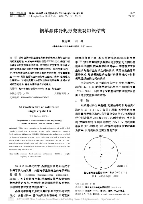
利用电子背散射衍射(EBSD )技术,表征了铜单晶体的形变微观组织结构。
在不同的应变量下,铜单晶体的形变微观组织结构存在着明显的差别。
低应变量(20%)下,其形变微观组织结构主要是高密度位错墙;应变量增高至50%时,其形变微观组织结构中还出现了微带、位错胞及位错胞块。
不同应变量下的微观组织结构的差异,主要由不同的形变阶段,晶体的滑移模式不同造成。
关键词:电子背散射衍射(EBSD );单晶;形变组织中图分类号:O 721文献标识码:A文章编号:100020054(2005)0620792203M icrostructure of cold rolledsi ngle crysta l CuWU Tingkun ,L I U W e i(D epart men t of M ater ials Sc ience and Engi neer i ng ,Tsi nghua Un iversity ,Be ij i ng 100084,Chi na )Abstract :T his paper repo rts on the m icro structure of co ld ro lled singlecrystal Cu m easured using fully autom atic electronbackscattered diffracti on (EBSD ).D ifferent size reducti ons resulted in different m icro structures .20%reducti on resulted in mo stly the dense dislocati on w all m icro structure .R educti ons of up to 50%m icroband created cells and cell block s in the m icro structure .T he m icro structure changes betw een samp les is due to changes in the sli p model during defo rm ati on .Key words :electronback scattereddiffracti on(EBSD );singlecrystal;m icro structure20世纪90年代以来,晶体微区取向分析技术取得了很大的发展。
- 1、下载文档前请自行甄别文档内容的完整性,平台不提供额外的编辑、内容补充、找答案等附加服务。
- 2、"仅部分预览"的文档,不可在线预览部分如存在完整性等问题,可反馈申请退款(可完整预览的文档不适用该条件!)。
- 3、如文档侵犯您的权益,请联系客服反馈,我们会尽快为您处理(人工客服工作时间:9:00-18:30)。
Microstructureevolutionduringtensiledeformationofananostructuredbainiticsteel
S.S.Babu,a,bS.Vogel,dC.Garcia-Mateo,eB.Clausen,cL.Morales-RivaseandF.G.Caballeroe,⇑
aDepartmentofMechanical,AerospaceandBiomedicalEngineering,407DoughertyEngineeringBuilding,
Knoxville,TN37996-2210,USAbDepartmentofMaterialsScienceandEngineering,407DoughertyEngineeringBuilding,Knoxville,TN37996-2210,USA
cMaterialsScienceandEngineering,OhioStateUniversity,Columbus,OH43221,USA
dLosAlamosNationalLaboratory,LujanCenter(LANSCE-LC),POBox1663,LosAlamos,NM87545,USA
eDepartmentofPhysicalMetallurgy,CentroNacionaldeInvestigacionesMetalu´rgicas(CENIM-CSIC),
10Avda.GregoriodelAmo8,E-28040Madrid,Spain
Received11June2013;revised27August2013;accepted27August2013Availableonline6September2013
Insituneutrondiffractionwasusedduringtensiletestingatroomtemperaturetoexaminethechangesintheproportionandtextureofbothferriteandausteniteinananocrystallinebainiticsteeltransformedattwodifferenttemperatures,200and300°C,fordifferenttimestoachievethesamephasepercentages.Bothsamplesshowedaninabilityofaustenitetotransformtomartensiteunderstraintotakefulladvantageofthetransformation-inducedplasticityeffect.Ó2013ActaMaterialiaInc.PublishedbyElsevierLtd.Allrightsreserved.
Keywords:Bainiticsteels;TRIPeffect;Neutrondiffraction;Texture
Anewgenerationofnanocrystallinesteelsreliesonabainiticmicrostructureformedatlowtemperaturethatcontainsplate-likeferriteandasignificantvolumepercentageofretainedaustenite.Thisretainedaustenitemaytransformintomartensiteduringthecourseofdeformation[1].Thisstress-orstrain-inducedtransfor-mationleadstoadditionalplasticity,whichproducesul-tra-high-strengthsteelswithstrengthstypically>2GPa,anincreaseinthework-hardeningrateduringplasticdeformation,aswellasanincreaseinuniformelonga-tionbydelayingnecking[2].However,iftheinitialex-tentoftheaustenitictobainitictransformationissmall,theuniformelongationwillbepoordespitetheretentionofalargevolumefractionofaustenite.Thisisbecausetheausteniteisfoundtooccurintwoforms:(i)micron/submicronblocksofretainedaustenitelo-catedbetweenthesheavesofbainite;and(ii)nanoscalefilmsofaustenitewhichareretainedbetweenthesub-unitswithinagivensheafofbainite[3].Thereisampleevidencethatthelargerretainedaustenite,whichislessenrichedincarbon[4],candecomposetomartensiteevenatrelativelysmallplasticstrains[3].Thestabilityoftheausteniteis,therefore,criticaltoobtaininggoodductilityinnanocrystallinebainiticsteels.Thegooduniformelongationpropertiesoftransfor-mation-inducedplasticity(TRIP)assistedsteelsaremainlyduetothecombineddeformationbehaviorofaustenite,ferriteandmartensitephaseswithdifferentconstitutiveproperties[5].Whenacompositemicro-structureisstressed,theplasticstrainisinitiallyfocusedinthemoreductilesoftphase,whichwork-hardens[6,7].Eventually,theharderphasealsodeformsplastically.Ryuetal.[8]experimentallydemonstratedthatthepar-titioningofstrainbetweenphasescandramaticallyinfluencethemechanicalstabilityofausteniteinTRIPsteels.Austenite,whichisharderthantheferrite,beginstodeformafterferritehaswork-hardened,experiencinglessdeformationthantheaverageelongationrecordedinthetensilespecimen.Othereffectsofretainedausteniteonductilitydis-cussedintheliteratureareblockingofmicrocrackpropagation[9],whichisrelatedtothehighdeformationstrengtheningabilityoftheaustenitethatimprovestheresistancetoslip[10,11];andthepossibilityofretainedausteniteactingasasinkfordislocationsfrom
1359-6462/$-seefrontmatterÓ2013ActaMaterialiaInc.PublishedbyElsevierLtd.Allrightsreserved.http://dx.doi.org/10.1016/j.scriptamat.2013.08.026
⇑Correspondingauthor.Tel.:+34915538900;fax:+34915347425;
e-mail:fgc@cenim.csic.es
Availableonlineatwww.sciencedirect.comScienceDirect
ScriptaMaterialia69(2013)777–780www.elsevier.com/locate/scriptamatneighbouringmartensitelaths,whichmayalsoallowthemartensitephasetodeformfurther.Inrecentyears,insituneutronand/orhigh-energyX-raydiffractionexperimentshaveledtonewinsightsintothedeformationbehavioroflow-alloyedTRIPsteels[12–17].However,duetothecomposite-likemicrostruc-tureandthecomplexdeformation/transformationbehaviorinthesematerials,thereportedneutronandsynchrotronexperimentsweredesignedtofocusonthestresspartitioningbetweentheconstituentphases.Theaimofthepresentpaperistoassessinsituthechangesinducedbytheappliedtensilestressonthephasefrac-tionandtextureofbothbainiticferriteandausteniteinananocrystallinebainiticsteel.Forthatpurpose,twosamplestransformedattwodifferenttemperatures(200and300°C),butcontainingthesamepercentageofaustenite(35%)werestudiedbyperforminginsituneutrondiffraction(ND)duringdeformation.Thechar-acteristicsofeachphase(amountandtexture)wereana-lyzedasafunctionoftheplasticstrain.Thesteel,withtheapproximatecompositionFe–0.8C–1.5Si–2Mn–1Cr–0.2Mo–1.5Co–1Al(wt.%),wassuppliedasahomogenizedingot.Detailsofthealloypreparationhavebeenpresentedelsewhere[18].Twospecimenswereaustenitizedfor30minat900°Candthenisothermallytransformedat200and300°Cfordif-ferenttimestoreachthesamedegreeofbainitetransfor-mation(65%)beforequenchingintowater.QuantitativeX-raydiffraction(XRD)analysiswasusedtodeterminethevolumefractionofretainedaustenite.Moreover,theausteniteandferritecarboncontentwascalculatedfromthemeasuredlatticeparameters[4].TextureanalysiswascompletedusingNDontheHIPPO(High-PressurePreferredOrientation)instru-mentattheLosAlamosNeutronScienceCenter(LAN-SCE)ofLosAlamosNationalLaboratories.Thisinstrumentusestheneutrontime-of-flighttechnique,i.e.itcollectsdiffractionspectraatseveraldetectorsusingawhiteneutronbeam(withinthewavelengthrange0.5–4.5A˚).Theangulardetectorcoverageisverylarge,andonlyfourexposuresatdifferentsamplerota-tionsarenecessarytocollectalargenumberofpolefig-ures,enablingtheabilitytoreconstructanorientationdistributionfunction(ODF).ThediffractionspectrawererefinedusingtheRietveldmethod[19]andthepolefiguresweregenerated.InsituNDtensiletestswerecarriedoutontheSpec-trometerforMaterialsResearchatTemperatureandStress(SMARTS)instrumentatLANSCE.Twodetec-tors,locatedat±90°fromtheincidentbeam,areavail-able,andthewavelengthrangeextendsfrom0.4to3.8A˚.AnInstrontestrig,equippedwithaloadcellof10kNwithtwotailoredsteelplates,wasmountedonthesamplestageoftheinstrument.Tensilestresswasappliedinastep-by-stepmannerandNDprofileswererecordedduringtemporarystopsofthecrossheadasshowninFigure1.Transmissionelectronmicroscopy(TEM)imagesoftheresultantmicrostructures,consistingofnanoscaleplatesofbainiticferrite(45–50nm),separatedbycar-bon-enrichedregionsofretainedaustenite,areshownelsewhere[3].ThevolumepercentageoftheaustenitewasdeterminedbyXRDtobe35%inbothsamples.However,theXRDdatalistedinTable1indicatedthatalthoughthesamepercentageofbainiticferritewasformed(65%)atbothtemperatures,theaustenitewasnotsimilarlyenrichedincarbon.Infact,themeasuredcarboncontentoftheausteniteat200°Cdemonstratesthatcarbonfailstopartitionintotheresidualaustenite[20].TheXRDdatainTable1alsoindicateacompara-blecarboncontentoftheferriteaftertransformationat200and300°C,andinbothsamplesthiscontentiswellabovethatexpectedfromparaequilibriumwithausten-ite(0.03wt.%).Thisbehaviorisattributedtothetrap-pingofcarbonatcrystaldefectssuchasdislocations,twinboundariesandinterfaces[21],andalsotoalargefractionofcarboninsolidsolutionwithintheferrite[22],botheventsconfirmedbyatomprobetomography.Themacroscopictensilestress–straincurvesinFig-ure1showedthatthemicrostructureobtainedbytrans-formationat300°Cexhibitedanuniformelongationof10%,higherthanthatat200°C,wheretheelongationisreducedto2%.Inthiscasealltheelongationwasuni-formandhardlyanyneckingwasobservedinthetestsamples.Thelargertrueuniformstrainsofthespecimentreatedat300°Cwasfoundtobeduetoacontinuousincrease(upto0.15)intheincrementalwork-hardeningcoefficientafteradecrease(downto0.05)atlowplasticstrains[3].Bycontrast,forthemicrostructureobtainedat200°C,theincrementalwork-hardeningcoefficientdisplayedacontinuousincrease(upto0.1)towardstheinstabilitycriteria,whichisneverreached,explainingthefactthatallthemeasuredelongationisuniform[3].TheNDdataarepresentedbyshowingthevolumefractionoftheconstituentphasesdistinguishableinthediffractionpatternsrecordedduringthedifferenttemporarystopsofthecrosshead,i.e.austenite(face-centeredcubic,fcc)andferrite(body-centeredcubic,bcc).Additionally,themartensiticbody-centeredtetrag-onal(bct)reflectionsstemmingfromthenewlyformedandsuitablyorientedmartensitephasearepartiallyorcompletelyoverlappedwithbainiticferritereflections,makingtheiranalysisvirtuallyimpossible[15].Thus,onlytwophaseswereconsideredinthecurrentanalysisoftheNDdata:theferritematrix(bainiticferriteandmartensiteintheplasticregion)andaustenite.Interpre-tationoftheferritematrixresultsmust,therefore,bedonecautiouslyduetopossibleoverlapwithmartensite.Theevolutionsoftheaustenitefractionasafunctionofdeformationforthetwobainiticmicrostructuresare