BL8023D 产品说明书
得力 S32 DZ32 DZ92 DL92系列扫描仪用户手册 说明书

5. 保养及维修扫描仪.................................................. 5-1
5.1 清理扫描仪玻璃镜片 ....................................... 5-1 5.2 清洁自动进纸装置 .......................................... 5-2 5.3 耗材更换 ..................................................... 5-3
蓝牙读卡器使用及测试说明2003
蓝牙读卡器使用说明1.接线端子及拨码开关说明:读卡器电路板上汉字标注,方便施工人员进展相关设置,请按照标注进展设置〔1〕信号强度调节开关12位:信号强度开关〔12位〕,为ON时信号逐步增强〔2〕地址拨码开关4位,用来设置读卡器的地址信息,读卡器反面有地址码设置对照表,请对照设置。
〔3〕道闸接线端子,接道闸起杆信号,当卡片信息有效时会发起杆信号给道闸。
〔4〕485接线端子,接485通信信号〔5〕地感接线端子,接地感线圈信号,可设置压地感读卡功能〔6〕韦根信号接线端子,输出韦根卡片内码。
〔7〕电源接线端子,接12V电源。
请按照端子标注正负接线,反接不通电。
:请注意不要在一个微机上同时接蓝牙读卡器和蓝牙写卡器。
请在设定完蓝牙读卡器信息后,拔下蓝牙读卡器电源或者485信号后,再插入蓝牙写卡器进展卡片信息设定。
读卡器接上485信号后,通电。
然后翻开上位机软件,软件自动搜索读卡器,如果通信成功那么读卡器上蓝灯会闪烁。
否那么上位时机提示通信失败,请检查读卡器是否通电,485信号是否连接正确,如果为USB转485〔232〕请检查是否正确安装驱动。
通信成功后软件界面如下:(1)读取读卡器时间首先输入控制器地址,然后点击读取控制器时间按钮,会显示当前控制器时间。
(2)校准读卡器时间首先输入控制器地址,然后点击控制器时间校准按钮,读卡器会自动同步微机当前时间。
(3)读取设备出厂日期点击读设备出厂日期按钮,会显示该读卡器出厂时间(4)设置读卡器密码输入控制器的原始密码,然后输入两遍新密码,如果需要启用压地感读卡,或者防回潜功能,勾选相应选项。
点击读卡器设定按钮。
读卡器蓝灯闪烁,并相应提示。
控制器出厂原始密码为空,一旦设定后请牢记新密码,否那么无法再次更改密码。
相应操作界面如下,十分简单(5)设置发卡器密码在发卡器密码框里输入需要设定的密码,点击发卡器密码设定按钮即可。
请注意:发卡器有两种型号:〔如不特殊要求默认为第一种型号〕1.下载发卡器密码后,物业每次写卡时会将发卡器密码及卡片到期时间一起写入卡片。
CTBMM300BLBLE 3 层抽屉服务车具有电源拓展板蓝色版说明书

OWNER'S MANUALCopyright © Professional Tool Products, 2018All rights reservedHARDWARE SPECIFICATIONSTOOLS NEEDED FOR ASSEMBLY:• 2 - 14mm Combination Wrenches • 13mm Socket or Universal Socket • 4" Extension• 1/4" Ratchet1a x 32 pcs.1b x 4 pcs. 2 x 72 pcs.3 x 16 pcs.24 x 40 pcs.4 x 4 pcs.9 x 16 pcs.Due to the weight of this cart we recommend that TWO PEOPLE work together on the assembly. This cart weighs approximately 170 lbs, please use caution during assembly. Step 1:Locate the key tied to the bottom tray. Using the key, open the lid and remove the caster box from the bottom drawer. Once removed make sure all drawers are completely closed and the inside lever is in the locked position. Close the top lid and lock.Step 2: Lay out a work surface using the protective foam provided. Once this surface is secure gently turn the cart onto its lid. (logo will be facing the foam)Step 3:(Before assembling the legs, remove the cable tie holding the bumper in place) Insert the front leg (#7), labeled FL or FR into top lip of the cart. Then place the Front bumper (#14 with Cornwell Logo) over the leg aligning the center bolt holes. With holes aligned insert stove bolt (#1a) and finger tighten with nyloc nut and washerStep 4:Install back leg (#7) labeled BL or BR and bumper (#14 without logo) following the same procedure as above. Note: Make sure the back leg is inside the hinge rivet. Otherwise the holes will not line up during assemblyASSEMBLY INSTRUCTIONSStep 7:Insert bottom shelf (#23) between the four legs flat side facing up towards the ceiling. Insert sixteen stove bolts (#1a) and completely tighten.Step 5:Repeat steps 3 & 4 to mount the legs on the opposite side. Step 6: Completely tighten the 8 bolts just inserted.Troubleshooting Points during CTBMM300 Assembly.Problem: Drawers appear not to fit, do not slide in accurately and bump the cart sides.Solution: The roller bearing slides must be fully engaged into the mounting slots on all drawers. They potentially could fall out of position while turning the cart on its lid, back, or onto its casters.Remove the drawer that is out of position. The drawer is removed by the two clips on the roller bearing slides.Simply push the roller bearing slide back down into position. Insert the drawer back onto the roller bearing slides.Problem: Back Lock/Unlock Switch does not engage the drawer.Solution: The inside Lock/Unlock slide potentially could fall out of its groove while turning the cart on its lid, back, or onto its casters during assembly.Unscrew the four screws that are holding the Lock/Unlock slide in place. Once the screws are removed simply place the latch back onto the slide and tighten the four screws back down.Problem: Back Lock/Unlock Switch does not engage the drawer.Solution: The inside Lock/Unlock slide potentially could fall out of its groove while turning the cart on its lid or back onto its casters.Unscrew the four screws that are holding the Lock/Unlock slide in place.Once the screws are removed simply place the latch back onto the slide and tighten the four screws back down.Step 13: Insert the remaining 8 stove bolts (#1a).Step 14: Using 13mm socket completely tighten all fasteners!!Step 15: Insert spray can holder divider (#19) into provided cutaway on the bottom shelf (#23). (Optional)ASSEMBLY INSTRUCTIONSStep 8:Mounting casters: Put the four casters in place. The two locking casters (#12) should be on one side of the cart and the two non locking casters (#10) should be on the other (Left or right side NOT front or back). Using the 16 bolts (#9), washers and fasteners (located in separate Caster bag) completely tighten the casters to the bottom tray using a 13mm socket and 14mm combination wrench for the bolt head. (Note: Bolt head and one washer should be on the inside of the bottom shelf, hex nut Step 10: Open top lid using the key providedStep 11: Mount push handle (#6) to the same side of the cart withthe locking casters using the four stove bolts (#1b) provided. Finger tighten at this time.Step 12: Insert the 4 Stove bolts (#4) provided to the opposite side of thecart. Note: This stove bolt is shorter due to not having to pass through a handle or bumper.TROUBLESHOOTINGI tem # Part # Description QTY. 1a M8 Bolt (6mm-17mm) 321b M8 Bolt (6mm-19mm) 42 Flat Washer (D8) 723 Hex Nut M8 164 M8 Bolt (3mm-17mm) 45 RSMM100HB Handle Brackets/Pair 16 RSMM100HDL Push Handle 17 RSMM300LGBK (Black) Leg 4RSMM300LGBL (Blue)RSMM300LGRD (Red)RSMM300LGRG (Orange)RSMM300LGNG (Neon Green)8 RSMM300SRPBK (Black) Screwdriver / Prybar holder 1 pairRSMM300SRPBL (Blue)RSMM300SRPRD (Red)RSMM300SRPRG (Orange)RSMM300SRPNG (Neon Green)9 Hex bolt M8-16 (for casters) 1610 RSSWCS 5" Swivel Caster (non-locking)/each 211 RSMM300RPBK (Black) Reinforced Piece /each 2RSMM300RPBL (Blue)RSMM300RPRD (Red)RSMM300RPRG (Orange)RSMM300RPNG (Neon Green)12 RSSWLCS 5" Swivel Caster with lock/each 213 RSMM300DHBL (Blue) Drawer Handle w/ Hardware 314 RSMM300BPRF Right Front Bumper 1RSMM300BPLF Left Front Bumper 1RSMM300BPLR Left Rear Bumper 1RSMM300BPRR Right Rear Bumper 115 Screw for Drawer Handles 1216 RSLKN Lock with Keys17 RSGP Gas Piston /each18 RSRBS Roller Bearing Slides/pair 319 RSMM300SCDBK (Black) Spray can divider 1RSMM300SCDBL (Blue)RSMM300SCDRD (Red)RSMM300SCDRG (Orange)RSMM300SCDNG (Neon Green)21 CTBMM3003DBK (Black) 3" Drawer 2CTBMM3003DBL (Blue)CTBMM3003DRD (Red)CTBMM3003DRG (Orange)CTBMM3003DNG (Neon Green)22 CTBMM3005DBK (Black) 5" Drawer 1CTBMM3005DBL (Blue)CTBMM3005DRD (Red)CTBMM3005DRG (Orange)CTBMM3005DNG (Neon Green)23 CTB300MMSBK (Black) Bottom shelf 1CTB300MMSBL (Blue)CTB300MMSRD (Red)CTB300MMSRG (Orange)CTB300MMSNG (Neon Green)24 Nylon Nut M8 4025 RSLMC300BKN (Black) Locking mechanism 1RSLMC300BLN (Blue)RSLMC300RDN (Red)RSLMC300RGN (Orange)RSLMC300NGN (Neon Green)26 RS50022 Power Strip w/ Cord 1 ALSO AVAILABLE:RSDET8PK Ball Bearing Slide Detents (Pk of 8),RSMM300LK 5pack EVA liner kitRSMM100DHP Plastic End Cap for Drawer Handle (2 pack)RSMM300BK4 Hardware Kit for opposite side of Push Handle (4 pc each #2, #4 & #24) RSMM300BK3 Caster Hardware Kit (each – 1 wheel) (4 pc each #3, #9 & 8 pc #2) RSMM300BK2 Push Handle Hardware Kit (4 pc each #1b, #2 & #24)RSMM300BK1 Leg/Bumper Hardware Kit (32 pc each #1a, #2 & #24)RS50022PC - Power Cord PART DRAWINGS5Push HandleBracket6Push Handle 7Legs (4)8Pry BarHolder (2)14Bumper (4)2 with logo, 2 without10Non-LockingCaster (2)11Front & BackBracket12Locking SwivelCaster (2)Narrow SideSmall Lip13DrawerHandle (3)19Paint CanHolder DividerPARTS LIST。
蓝光切胶仪BL-20操作说明书

操作说明书Operations Manual BL-20LED Transilluminator蓝光切胶仪目录前言 (1)开箱检查 (1)第一部分安全信息 (2)1.安全操作信息 (2)2.安全提示 (2)第二部分产品说明 (3)1.产品简介 (3)2.产品特性 (3)3.使用环境 (3)4.技术参数 (4)第三部分功能介绍 (5)产品结构图 (5)第四部分操作说明 (6)1.仪器准备 (6)2.仪器操作 (6)第五部分故障排除 (7)第六部分维护与清洁 (8)第七部分售后服务 (9)1.保修说明 (9)2.保修范围 (9)订购信息 (10)1.配件信息 (10)2.联系我们 (10)附件A装箱清单 (11)附件B BL-20紫外切胶仪性能检测表 (12)前言感谢购买BL-20蓝光切胶仪。
本用户手册包含了仪器的功能和操作过程等,为了确保正确使用仪器,在操作仪器前请仔细阅读本手册。
请妥善保存手册,以便碰到问题时快速阅读和解决。
开箱检查用户收到产品时应及时打开仪器包装箱,对照装箱清单检查仪器和配件,若发现仪器或配件包装错误、数量不对、包装或产品破损等情况,请在7天内及时与销售商或生产商联系,超过此时间将不予按照非产品质量问题处理原则处理。
第一部分安全信息1.安全操作信息用户在操作仪器之前,请仔细阅读本手册,并对如何正确和安全操作本仪器有一个完整和清晰的了解。
2.安全提示只能在接地电路中使用该仪器。
打开光源时,不要盯着光束。
因不当操作导致的损伤,本公司不予承担责任。
本仪器及配件应放置在清洁、干燥、通风、无腐蚀性和避免太阳直接照射的场所。
在使用过程中,不要用湿手触摸设备,以防电击。
清洁或维护前,请务必断开电源。
在使用时,请先确保琥珀色滤光片安装良好且仪器工作时严禁与水等液体接触,防止仪器内部的电路短路。
请勿在有潜在爆炸性环境的区域及易燃材料附近使用本仪器。
装箱所有配件仅限与本仪器配合使用,不能用于其他仪器。
BL8023 说明书
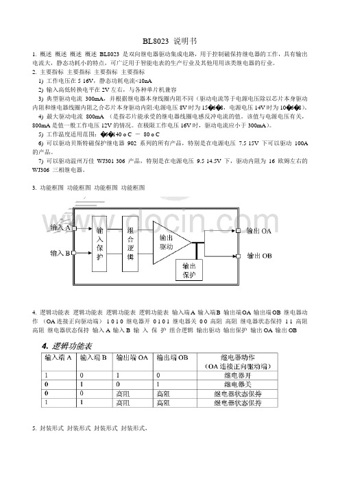
BL8023 说明书1. 概述概述概述概述BL8023 是双向继电器驱动集成电路,用于控制磁保持继电器的工作,具有输出电流大,静态功耗小的特点,可广泛用于智能电表的生产行业及其他用用该类继电器的行业。
2. 主要指标主要指标主要指标主要指标1) 工作电压在5-16V,静态功耗电流<10nA2) 输入高低转换电平在2V左右,与各种单片机兼容3) 典型驱动电流300mA,并根据继电器本身线圈内阻不同(驱动电流等于电源电压除以芯片本身驱动内阻和继电器线圈内阻之合芯片本身驱动内阻:电源电压8V时为15�6�8,电源电压14V时为10�6�8)。
4) 最大驱动电流800mA(是指芯片能承受的继电器线圈电感反冲电流的值。
该值与电源电压有关,800mA是值一般工作电压12V的情况。
在极限工作电压16V时,驱动电流应小于300mA)。
5) 工作温度适用范围:�6�140 o C -80 o C6) 可以驱动贝斯特磁保护继电器902 系列的所有产品,特别是在电源电压7.5-15V 下可以驱动100A 的产品。
7) 可以驱动温州万佳WJ301-306 产品,特别是在电源电压9.5-14.5V下,驱动内阻为16 欧姆左右的WJ306 三相继电器。
3. 功能框图功能框图功能框图功能框图4. 逻辑功能表逻辑功能表逻辑功能表逻辑功能表输入端A输入端B 输出端OA输出端OB 继电器动作(OA连接正向驱动端)1 0 1 0 继电器开0 1 0 1 继电器关0 0 高阻高阻继电器状态保持1 1 高阻高阻继电器状态保持输入A输入B 输入保护组合逻辑输出驱动输出保护输出OA输出OB5. 封装形式封装形式封装形式封装形式,管脚排列及功能管脚排列及功能管脚排列及功能管脚排列及功能有两种封装形式可选:DIP8 脚封装SOP8 脚封装6. 应用电路应用电路应用电路应用电路1) 脉冲触发脉冲触发脉冲触发脉冲触发输入端A,B用脉冲触发,只要直接把输入端与相应器件的输出端连接就可以工作。
Omron 光导联接开关产品说明书

1B3W-9Illuminated Tactile SwitchesCompact Illuminated Tactile Switch with 2 LEDs•Compact construction 10 × 10 × 11 mm (W × D ×H) and 12 × 12 × 11 mm (W × D × H) with bright and uniform illumination.•Three-color illumination (red LED + green LED =orange).•Standard force (1.57 N) and high-force (2.26 N)models.■Features■Model Number Legend1.Cap width 0:10 × 10 mm 1:12 × 12 mm2.Operating force0:Standard (OF = 1.57 N {160 gf})2:High-force (OF = 2.26 N {230 gf})3.LED colorR:Red G:GreenHG:Green (high brightness)Y:Y ellow B:BlueRG:Red + Green (Combination of LED colors)RB:Red + Blue (Combination of LED colors)4.No. of LEDs 1:12:25.CapR:Red G:Green Y:Y ellow B:BlueC:Transparent N:Milky whiteNote:Detail information of ordering can be found on p.2.RoHS Compliant11 mm × D■List of Models10 × 10-mm SwitchesStandard force High-force Force LED color No. ofLEDsCap color ModelStandard force(OF = 1.57 N)Blue1Blue B3W-9000-B1B1Transparent B3W-9000-B1C1Milky white B3W-9000-B1N2Blue B3W-9000-B2B2Transparent B3W-9000-B2C2Milky white B3W-9000-B2NGreen1Transparent B3W-9000-G1C1Green B3W-9000-G1G1Milky white B3W-9000-G1N2Transparent B3W-9000-G2C2Green B3W-9000-G2G2Milky white B3W-9000-G2NGreen(highbrightness)1Transparent B3W-9000-HG1C1Green B3W-9000-HG1G1Milky white B3W-9000-HG1N2Transparent B3W-9000-HG2C2Green B3W-9000-HG2G2Milky white B3W-9000-HG2NRed1Transparent B3W-9000-R1C1Milky white B3W-9000-R1N1Red B3W-9000-R1R2Transparent B3W-9000-R2C2Milky white B3W-9000-R2N2Red B3W-9000-R2RRed +Green2Transparent B3W-9000-RG2C2Milky white B3W-9000-RG2NRed + Highbrightgreen2Transparent B3W-9000-RHG2CRed + Blue2Transparent B3W-9000-RB2CYellow1Transparent B3W-9000-Y1C1Milky white B3W-9000-Y1N1Yellow B3W-9000-Y1Y2Transparent B3W-9000-Y2C2Milky white B3W-9000-Y2N2Yellow B3W-9000-Y2YForce LED color No. ofLEDsCap color ModelHigh-force(OF = 2.26 N)Blue1Blue B3W-9002-B1B1Transparent B3W-9002-B1C1Milky white B3W-9002-B1N2Blue B3W-9002-B2B2Transparent B3W-9002-B2C2Milky white B3W-9002-B2NGreen1Transparent B3W-9002-G1C1Green B3W-9002-G1G1Milky white B3W-9002-G1N2Transparent B3W-9002-G2C2Green B3W-9002-G2G2Milky white B3W-9002-G2NGreen(highbrightness)1Transparent B3W-9002-HG1C1Green B3W-9002-HG1G1Milky white B3W-9002-HG1N2Transparent B3W-9002-HG2C2Green B3W-9002-HG2G2Milky white B3W-9002-HG2NRed1Transparent B3W-9002-R1C1Milky white B3W-9002-R1N1Red B3W-9002-R1R2Transparent B3W-9002-R2C2Milky white B3W-9002-R2N2Red B3W-9002-R2RRed +Green2Transparent B3W-9002-RG2C2Milky white B3W-9002-RG2NRed + Highbrightgreen2Transparent B3W-9002-RHG2CRed + Blue2Transparent B3W-9002-RB2CYellow1Transparent B3W-9002-Y1C1Milky white B3W-9002-Y1N1Yellow B3W-9002-Y1Y2Transparent B3W-9002-Y2C2Milky white B3W-9002-Y2N2Yellow B3W-9002-Y2Y2312 × 12-mm SwitchesStandard forceHigh-force■Ratings/Characteristics (Same for Both Standard and High-force Switches)■Operating CharacteristicsForce LED color No. of LEDs Cap color Model Standard force(OF = 1.57 N)Blue (high brightness)1Blue B3W-9010-B1B 1Milky white B3W-9010-B1N 2Blue B3W-9010-B2B 2Milky white B3W-9010-B2N Green1Green B3W-9010-G1G 1Milky white B3W-9010-G1N 2Green B3W-9010-G2G 2Milky white B3W-9010-G2N Green (highbrightness)1Green B3W-9010-HG1G 1Milky white B3W-9010-HG1N 2Green B3W-9010-HG2G 2Milky white B3W-9010-HG2N Red1Red B3W-9010-R1R 1Milky white B3W-9010-R1N 2Red B3W-9010-R2R 2Milky white B3W-9010-R2N Red + Green 2Milky white B3W-9010-RG2N Red + High bright green 2Milky whiteB3W-9010-RHG2NRed + Blue 2Milky white B3W-9010-RB2N Yellow1Yellow B3W-9010-Y1Y 1Milky white B3W-9010-Y1N 2Yellow B3W-9010-Y2Y 2Milky whiteB3W-9010-Y2NForceLED colorNo. of LEDs Cap color Model High-force (OF = 2.26 N)Blue 1Blue B3W-9012-B1B 1Milky white B3W-9012-B1N 2Blue B3W-9012-B2B 2Milky white B3W-9012-B2N Green 1Green B3W-9012-G1G 1Milky white B3W-9012-G1N 2Green B3W-9012-G2G 2Milky white B3W-9012-G2N Green (high bright-ness)1Green B3W-9012-HG1G 1Milky white B3W-9012-HG1N 2Green B3W-9012-HG2G 2Milky white B3W-9012-HG2N Red1Red B3W-9012-R1R 1Milky white B3W-9012-R1N 2Red B3W-9012-R2R 2Milky white B3W-9012-R2N Red + Green2Milky white B3W-9012-RG2N Red + High bright green 2Milky whiteB3W-9012-RHG2NRed + Blue2Milky white B3W-9012-RB2N Yellow1Yellow B3W-9012-Y1Y 1Milky white B3W-9012-Y1N 2Yellow B3W-9012-Y2Y 2Milky whiteB3W-9012-Y2NRatings1 to 50 mA, 5 to 24 VDC (resistive load)Ambient operating temperature −25°C to +70°C at 60% max. humidity (with no icing or condensation)Ambient operating humidity 35% to 85% (at +5 to +35°C)Contact form SPST-NOContact resistance 100 m Ω max. (initial value) (rated: 1 mA, 5 VDC)Insulation resistance 100 M Ω min. (at 250 VDC)Dielectric strength 500 VAC, 50/60 Hz for 1 min Bounce time 5 ms max.Vibration resistance Malfunction: 10 to 55 Hz, 1.5 mm double amplitude Shock resistance Destruction: 1,000 m/s 2 {approx. 100 G} max.Malfunction: 100 m/s 2 {approx. 10 G} max.DurabilitySwitch section1.57 N (standard force):1,000,000 operations min.2.26 N (high-force):300,000 operations min.ItemStandard-force Switches (B3W-90@0)High-force Switches(B3W-90@2)Operating force (OF) 1.57 N {160 gf} max. 2.26 N {230 gf} max.Releasing force (RF)0.2 N {20 gf} min.0.49 N {50 gf} min.Pretravel (PT)0.25+0.2/−0.1 mm4■LED Specifications(Ambient temperature Ta = 25°C)Note:For Switches with two LEDs, red and green, the recommended operating current is 12 mA for the red and 20 mA for the green LED for application with three-color illumination.■LEDs●Forward current reduction curve●Forward current and forward voltage curvesNote:1.Make sure that the polarity of the LEDs is correct. The polarity is not indicated on the Switch, but the positive pole is located on the back surface of the Switch on the side with the OMRON mark.2.Connect limiting resistors to the LEDs. The Switch does not have built-in limiting resistors, so satisfy the LED characteristics by obtaining the limiting resistance according to the following formula based on the voltage to be used.LED colorRedGreenGreen (high brightness)YellowBlueMaximum operating current I FM 27 mA 27 mA 27 mA 45 mA 27 mA Recommended operating current I F 20 mA 20 mA 10 mA 20 mA 10 mA Forward voltage (standard value) V F 1.8 V 2.1 V 3.7 V 2.4 V 3.7 V Maximum reverse voltage V R 5 V5 V5 V5 V5 VAmbient operating temperature−25°C to 70°C■Dimensions(Unit: mm)1 LED TypesB3W-900@-@1@B3W-901@-@1@2 LED TypesB3W-900@-@2@B3W-901@-@2@Note:Unless otherwise specified, a tolerance of ±0.4 mm applies to all dimensions. No terminal numbers are indicated on the Switches.56■AccessoriesB3W-9@@-F @Text Combination FilmsText Combination Films for B3W-9 Illuminated Tactile Switches•Display two different labels in combination with a 2-LED B3W-9 Switch. •Color combinations: Red/Green or Red/Blue■Model Number Legend1.ColorR:Red 2.ColorB:Blue G:Green3.Color and text combinationF1:Red OFFBlue or green ONF2:Red (OFF)Blue or green (ON)F3:Red (C L OSE)Blue or green (OPEN)F4:RedBlue or green F5:RedBlue or green Note:1.Five text combinations are available.2.Films can also be customized with other text for 50sheets (1,250 films) per lot. Delivery time is approxi-mately five weeks. (Ask your OMRON representative for details.)■Recommended B3W-9 Switches■Minimum Order25 films/sheetB3W-9 Films are sold in units of 25 films. Orders must be made in multiples of 25 (the quantity per sheet).Note:Text Combination Films are sold without the Switches. Or-der one of the above models of B3W-9 Illuminated Tactile Switches separately.Operating force2-LED SwitchesRed/BlueRed/Bright green Standard-force Switches B3W-9000-RB2C B3W-9000-RHG2C High-force Switches B3W-9002-RB2CB3W-9002-RHG2C■Safety PrecautionsNote:Refer to Safety Precautions in Tactile Switches (Cat. No. X037) for details on general safety precautions.■Precautions for Correct UseElectrical StandardsUse the Switch within the rated voltage and current ranges, other-wise the Switch may have a shortened life expectancy, radiate heat, or burn out. This particularly applies to the instantaneous voltages and currents when switching.Soldering1. Soldering Precautions•Before any kind of soldering, test to confirm that soldering can be performed properly. Otherwise the Switch may be deformed by the soldering heat depending on the type of PCB, pattern, or lands of the PCB.•Do not solder the Switch more than twice, including rectification soldering. Wait for at least five minutes between the first and sec-ond soldering to allow the temperature to return to normal. Con-tinuous soldering may cause the casing to melt or deteriorate the Switch characteristics.2. Automatic Soldering Baths (Wave Soldering)•Soldering temperature: 260°C max.•Soldering time: 5 s max. for a 1.6-mm thick single-side PCB •Preheating temperature: 100°C max. (ambient temperature)•Preheating time: Within 60 s•PrecautionsMake sure that no flux will rise above the level of the PCB. Also make sure that flux is not applied to the switch terminals or to the mounting surface of the PCB.If flux overflows onto the mounting surface of the PCB, it may en-ter the Switch and cause a malfunction.3. Manual Soldering•Soldering temperature: 350°C max. at the tip of the soldering iron •Soldering time: 3 s max. for a 1.6-mm thick, single-side PCB •Precautions:Before soldering the Switch on a PCB, make sure that there is no unnecessary space between theSwitch and the PCB.WashingStandard Switches are not sealed, and cannot be washed. Doing so will cause the washing agent, together with flux or dust parti-cles on the PCB, to enter the Switch, resulting in malfunction. PCBsThe Switch is designed for a 1.6-mm thick, single-side PCB. Using PCBs with a different thickness or using double-sided, through-hole PCBs may result in loose mounting, improper inser-tion, or poor heat resistance in soldering. These effects will occur, depending on the type of holes and patterns of the PCB. There-fore, it is recommended that a verification test is conducted before use. Handling1. Usage EnvironmentBefore installing the Switch, make sure that the area of installa-tion is not subject to corrosive gases emitted from surrounding parts.Do not use in areas subject to high temperatures, high humidity, or toxic gases such as sulfuric gas (H2S, SO2), ammonia gas (NH3), nitric gas (HNO3), or chlorine gas (CI2). It can cause corro-sive damage to the contacts and result in malfunction.If there is silicon in the atmosphere, it may stop the contacts from functioning properly.If silicon products, such as silicon oil, silicon filler, or silicon wires, are used in the surrounding area, install a contact protection cir-cuit to prevent arching or remove the silicon source.The following situations may cause water to enter inside the Switch, resulting in a malfunction due to contact failure or corro-sion.•Using the Switch in an outdoor environment where it is exposed to water drops for an extended period of time.•Using the Switch in an underwater setting where it is subject to strong water pressure.Do not use Switches that have been dropped. The mating section or other internal parts may be damaged, resulting in malfunction. OperationDo not repeatedly operate the Switch with excessive force. Apply-ing excessive pressure or applying additional force after the plunger has stopped may deform the disk spring of the Switch, resulting in malfunction.Be sure to set up the Switch so that the plunger will operate in a straight vertical line.If the plunger is pressed of-center or from an angle it may cause deformation or damage to some parts. This may result in deterio-ration of durability or malfunction.Dust ProtectionDo not install or use Switches in dust-prone environments. If a Switch must be used in this kind of environment, use a protective sheet or take other measures to protect it against dust.Note:Switches with high-brightness green (HG) or blue (B) LEDs are susceptible to static electricity. Be careful whenhandling a Switch with these LEDs as it may cause theSwitch to breakdown.7Removing the Cap1.Hold the cap at the side away from the mating section. Pullstraight up.2.Do not remove the cap while the Switch is mounted. Doingso will apply force to the soldered section and LEDs, result-ing in malfunction.Placing the Cap on the SwitchHold the Cap at the side away from the mating section. Push straight down until the mating section meets.Removing the CapThe Cap can be removed up to two times. Excessively removing the Cap will cause the mating section to become weak, resulting the operating section not mating completely or the Cap may fall off.Film DimensionsDimensions of the film are shown below. The thickness is 0.2 mm.Storage PrecautionsStorage EnvironmentT o prevent degradation, such as discoloration, of the terminals during storage, do not store the Switch in locations that are sub-ject to the following conditions.1. High temperature or humidity2. Corrosive gases3. Direct sunlightStorage conditionStore the Switches in the packaging box.After the packaging box is opened, use the contents as quickly as possible. When storing leftover parts, make sure that appropriate measures are taken against humidity and corrosive gases. Agreement of Product UseComply with the usage, storage, and disposal conditions speci-fied by OMRON as outlined in the precautions in the product datasheet and specifications.Correct IncorrectCorrectIncorrect。
东芝 拨号显示器 使用说明书
拨号显示器使用说明书D -R ,D -L ,D -C ,D 381.前言对采购本产品表示真挚的感谢!使用本产品前请详细阅读本“使用说明书”,并正确的进行使用。
本使用说明书请务必要交付与最终终端用户。
1-1. 打开包装时首先,确认以下几点(1)确认产品是否有误。
(2)确认产品在运输途中是否产生破损。
1-2. 如有不良情况发生,请咨询产品实际购买处。
2.安全上的注意事项在使用本产品的时候,请仔细阅读本说明书以及其他的技术资料等,同时注意安全。
并且,请保管好本说明书方便必要的时候阅读,务必要将本说明书交付与终端用户手中。
另外,此“安全上的注意事项”在无事先通知的情况下,会进行一些修改以及变更,敬请谅解。
在此说明书中,安全注意事项的等级使用“危险”“注意”来进行区分,用警告图记号来对有关使用行为进行具体区分。
另外,安全等级虽用“注意”进行标示,根据情况不同也会产生较严重的后果。
不论哪个事项都为重要内容,请务必遵守。
危险使用者在使用不当的情况下会有死亡以及重伤的情况发生,并且表示发生如上情况的可能性很高。
注意使用者在使用不当的情况下会有受害的情况发生,并且有可能发生经济损失。
【安全注意事项等级】禁止产品的使用过程中,表示此行为被禁止。
注意产品的使用过程中,表示需要注意。
指示产品的使用过程中,表示必须按照指示进行。
【警告图记号说明】产品的故障、误操作等会直接对性命或者人身安全产生危害的装置(核能、航空宇宙、医疗、交通机器、各种安全装置等)上使用本产品时,请提前联系我们公司。
本产品对于品质的管理把控是非常严格的,为了防止故障等的发生,机械设备上的安全对策也请务必考虑周全。
危险本产品在运作中时用手或者手指等去触碰会受伤。
为了防止此类危险发生,请必定设置安全保护盖。
与此同时,请设置安全机构,使安全保护盖被打开后,本产品会马上停止运作。
绝对不要使用在油脂、可燃性气体等容易引起火灾、爆炸的场合。
直接安装使用在有灰尘、高温、结露、暴露在风雨中的场所,以及会受到震动、冲击等场合,会对产品造成损伤、故障或者导致性能的低下的情况发生,请注意。
D40ML系列RFID磁锁产品说明书
1Stainless SteelPlasticDie-cast MetalMagnetic latching combines with RFID technology to deliver high holding force and tamper resistance•RFID provide s a high degree of t a mper re s i s t a nce.•Cle a n/Sa nitize in Pl a ce – s t a inle ss s teel ver s ion s a re r a ted IP69K •LED s s upport e as y f a ult di a gno s i s •In s t a ll up to 20 s witche s in s erie s•Re s idu a l m a gneti s m a ct s as light door l a tch a fter unlocking •Two a ctu a tor type s with type 4 coding•B as ic – a ll a ctu a tor s in the s y s tem a re identic a lly coded.•Unique – every a ctu a tor i s individu a lly coded. 32,000,000 code s •Both offer toler a nce for mi sa lignment•Two s witch s ize s provide multiple holding force option s •Medium Duty-S t a inle ss S teel: F1m a x (typic a l) 600N, F zh 450N -Pl as tic a nd Diec as t: F1m a x (typic a l) 900N, F zh 675N •He a vy Duty-S t a inle ss S teel: F1m a x (typic a l) 950N, F zh 700N-Pl as tic a nd Diec as t: F1m a x (typic a l) 1500N, F zh 1150N •Three c as e m a teri a l sPl as tic, diec as t met a l, 316 s t a inle ss s teel•For u s e on m a chine s with no rundown time if power i s lo s tDiagnostic Indicator FunctionYellow LED indicates OPENS hown in Gu a rd Open Po s itionGreen LED indicates CLOSEDS hown in Gu a rd Clo s ed Po sition Switch StatusGuard Green LED Yellow LEDSafety OutputLockedClo s ed S te a dy Off Clo s ed S olenoid Power OFF (unlocked)Clo s ed Fl as hing Off Open Gu a rd Open Open Off S te a dy Open Door Forced OpenOpenOffFl as hingOpenD40ML Series2Ordering InformationSwitchesSpare ActuatorsNote:S p a re a ctu a tor s a re not a v a il a ble for uniquely coded s witche s.AccessoriesNote:1.The quick di s connect c a ble h as a n identic a l c a ble pining as the Cable Wiring on p a ge 42.Y92E-M12PUR S H8S M-L di s connect c a ble s a re a l s o comp a tible with D40ML.Case Material Holding Force F1max (typical)Actuator Type Cable Configuration Model Number316 S t a inle ssS teel (IP69K)600NUnique5m C a ble D40ML-SS2-U-5M10m C a ble D40ML-SS2-U-10MPigt a il w/ M12 Connector D40ML-SS2-U-M12B as ic5m C a ble D40ML-SS2-B-5M10m C a ble D40ML-SS2-B-10MPigt a il w/ M12 Connector D40ML-SS2-B-M12 950NUnique5m C a ble D40ML-SS1-U-5M10m C a ble D40ML-SS1-U-10MPigt a il w/ M12 Connector D40ML-SS1-U-M12B as ic5m C a ble D40ML-SS1-B-5M10m C a ble D40ML-SS1-B-10MPigt a il w/ M12 Connector D40ML-SS1-B-M12Pl as tic (IP67)900NUnique5m C a ble D40ML-P2-U-5M10m C a ble D40ML-P2-U-10MPigt a il w/ M12 Connector D40ML-P2-U-M12B as ic5m C a ble D40ML-P2-B-5M10m C a ble D40ML-P2-B-10MPigt a il w/ M12 Connector D40ML-P2-B-M12 1500NUnique5m C a ble D40ML-P1-U-5M10m C a ble D40ML-P1-U-10MPigt a il w/ M12 Connector D40ML-P1-U-M12B as ic5m C a ble D40ML-P1-B-5M10m C a ble D40ML-P1-B-10MPigt a il w/ M12 Connector D40ML-P1-B-M12Diec as t Met a l(IP67)900NUnique5m C a ble D40ML-M2-U-5M10m C a ble D40ML-M2-U-M12Pigt a il w/ M12 Connector D40ML-M2-U-M12B as ic5m C a ble D40ML-M2-B-5M10m C a ble D40ML-M2-B-10MPigt a il w/ M12 Connector D40ML-M2-B-M12 1500NUnique5m C a ble D40ML-M1-U-5M10m C a ble D40ML-M1-U-10MPigt a il w/ M12 Connector D40ML-M1-U-M12B as ic5m C a ble D40ML-M1-B-5M10m C a ble D40ML-M1-B-10MPigt a il w/ M12 Connector D40ML-M1-B-M12Product Description Model Number S t a inle ss S teel; IP69K; 950N; B as ic Code; Actu a tor D40ML-SS1-B-ACTS t a inle ss S teel; IP69K 600N; B as ic Code; Actu a tor D40ML-SS2-B-ACT Diec as t Met a l; IP67; 1500N; B as ic Code; Actu a tor D40ML-M1-B-ACTDiec as t Met a l; IP67; 900N; B as ic Code; Actu a tor D40ML-M2-B-ACTPl as tic; IP67; 1500N; B as ic Code; Actu a tor D40ML-P1-B-ACTPl as tic; IP67; 900N; B as ic Code; Actu a tor D40ML-P2-B-ACTProduct Description Model Number Quick Di s connect C a ble, 8-pin M12 to Flying Le a d s, PVC J a cket, 5 Meter Length D40ML-CBL-M12-5M Quick Di s connect C a ble, 8-pin M12 to Flying Le a d s, PVC J a cket, 10 Meter Length D40ML-CBL-M12-10MD40ML Series3SpecificationsNote:When the product u s e devi a te s from the s e ass umption s (different lo a d, oper a ting frequency, etc.) the v a lue s mu s t be a dju s ted a ccordingly.Codes and StandardsIEC 60947-5-3:2013, EN 60947-5-1:2004 + AC:2005 + A1:2009, EN 60947-1:2007 + A1:2011, EN I S O 13849-1:2008 + AC:2009, EN 62061:2005 + AC:2010 + A1:2013, I S O 14119:2013, UL508Safety Classificationand Reliability Data Minimum Switched Current 10VDC 1mA Dielectric Withstand 250VAC Insulation Resistance 100M ΩShock Resistance 11m s 30GVibration Resistance 10 to 55Hz, 1mm a mplitude Switching Distance S a o 1mm Clo s e; S a r 10mm OpenMisalignment Between s witch a nd a ctu a tor, 2mm in a ny direction Switching Frequency 1.0Hz m a ximum Response Time (On –> Off)10m s m a x.Operating Time (Off –> On)150m sApproach Speed200mm/m to 1000mm/sBody MaterialD40ML-P_: Pl as ticD40ML-M_: Diec as t Met a lD40ML-SS _: 316 S t a inle ss S teel Actu a tor S e a l: S iliconeEnc a p s ul a tion: High Temper a ture Epoxy Operating Temperature Range–25 to 40°CAmbient Operating Humidityup to 90% a t 25 ~ 40°CEnclosure Protection IP67 (Pl as tic or Diec as t Met a l)IP69K (S t a inle ss s teel ver s ion s with flying le a d s )Cable Type PVC 8 core, 6mm outer di a meter Mounting Bolts 2 × M5 Tightening torque 1.0Nm Mounting Position AnyPower Supply 24VDC ±10% (s elv / pelv)Power ConsumptionUnlocked: 50mA m a x.Locked:- Medium Duty 325mA m a x. - He a vy Duty 500mA m a x.Holding ForceMedium Duty- S t a inle ss S teel: F1m a x (typic a l) 600N, F zh *1 450N - Pl as tic a nd Diec as t: F1m a x (typic a l) 900N, F zh 675N He a vy Duty- S t a inle ss S teel: F1m a x (typic a l) 950N, F zh 700N- Pl as tic a nd Diec as t: F1m a x (typic a l) 1500N, F zh 1150N *1A new te s t h as been introduced with the coefficient 1.3. A device with a s pecified m a ximum holding force (F zh ) of 500N need s to hold up a force te s t (F1m a x ) a t 650N.According to the s t a nd a rd the locking force F zh s hould be s t a ted for every gu a rd locking s witch.Max. Switched Current (Outputs)200mA (min. intern a l re s i s t a nce 8.5 Ohm s )Auxiliary Signal+24 VDC (Door Open)Characteristic Data according to EN ISO13849-1PLe: If both ch a nnel s a re u s ed in combin a tion with a S IL3/PLe control device C a tegory: C a t. 4MTTFd: 1100aDi a gno s tic Cover a ge DC: 99% (high)Number of oper a ting d a y s per ye a r: d op = 365d Number of oper a ting hour s per d a y: h op = 24h B10d: Not mech a nic a l p a rt s implemented Characteristic Data according to IEC62061 (used as a sub system)Sa fety Integrity Level: S IL3PFH (1/h): 4.77E-10 Corre s pond s to 4.8% of S IL3PFD: 4.18E-05 Corre s pond s to 4.2% of S IL3Proof Te s t Interv a l T 1: 20aInformation with regard to UL508U s e LVLC or Cl ass 2 s upply. Type 1 enclo s ure.Risk Time in accordance with EN 60947-5-3150m s (s witching off del a y a t remov a l of a ctu a tor)D40ML Series4Cable WiringTypical Operating Distance (Front Approach)Note:DO NOT u s e s witch a nd a ctu a tor as a gu a rd door stop.Solenoid Supply 24 VDCAuxSafety Output 2Safety Output 1External Supply 24 VDCNon-Contact RFID Locking Switch Wiring DiagramQuick Connect(CC)M12 8-way maleplugConductorColorsFunction Power Rating8Or a ngeApply Lock(24VDC ±10%)50mA M a x5BrownAuxili a ry S ign a l(Door Open/Clo s ed)+24VDC(200mA)4Yellow Sa fety Output 2200mA M a x6Green Sa fety Output 21White Sa fety Output 1200mA M a x7Bl a ck Sa fety Output 13Blue0VDC500mA M a x2Red+24VDC ±10%Misalignment mmDistance mmD40ML Series5Dimensions(Unit: mm)D40ML Medium Duty SwitchD40ML Heavy Duty SwitchInstallation:•In s t a ll a tion of a ll D40ML s erie s sa fety s witche s mu s t be in a ccord a nce with a ri s k ass e ss ment for the individu a l a pplic a tion.•The u s e of a sa fety rel a y i s required for monitoring RFID coded s witche s . The s e rel a y s monitor two redund a nt circuit s as per I S O13849-1 for up to PLe/C a tegory 4 protection.•D40ML s erie s s witche s a re de s igned to oper a te with mo s t du a l ch a nnel sa fety rel a y s to sa ti s fy EN60947-5-3.•M5 mounting bolt s mu s t be u s ed to mount the s witche s . Tightening torque for mounting bolt s to en s ure reli a ble fixing i s 1.0 Nm. Alw a y s mount on non-ferrou s m a teri a l s .•Do not mount a dj a cent s witche s or a ctu a tor s clo s er th a n 30mm.•To a chieve nomin a l holding force en s ure f a ce-to-f a ce a lignment of m a gnetic p a rt s .•After in s t a ll a tion a lw a y s check e a ch s witch function by opening a nd clo s ing e a ch gu a rd individu a lly in turn a nd en s uring th a t the Green LED on the s witch a nd the LED s on the sa fety rel a y a re illumin a ted when the s witch i s clo s ed a nd a re extingui s hed when the s witch i s open. Check th a t the m a chine s top s a nd c a nnot be re-s t a rted when e a ch s witch i s open.Maintenance/Safety Checks: Monthly: Check a lignment of a ctu a tor a nd look for s ign s of mech a nic a l d a m a ge to the s witch c as ing or c a ble s .The sa fety function s a nd mech a nic s mu s t be te s ted regul a rly. For a pplic a tion s where infrequent gu a rd a cce ss i s fore s ee a ble, the s y s tem mu s t h a ve a m a nu a l function te s t to detect a po ss ible a ccumul a tion of f a ult s . At le as t once per month for PLe C a t3/4 or once per ye a r for PLd C a t3 (I S O13849-1). Where po ss ible it i s recommended th a t the control s y s tem of the m a chine dem a nd s a nd monitor s the s e te s t s , a nd s top s or prevent s the m a chine from s t a rting if the te s t i s not done. (I S O14119). Check th a t the m a chine s top s a nd c a nnot be re-s t a rted when e a ch s witch i s open.NOTE: The sa fety output s will only clo s e when the a ctu a tor i s in pl a ce a nd the lock m a gnet i s energized. Forcing open of the lock will c a u s e the sa fety output s to open.IMPORTANT: The gu a rd holding h as no interlock function. The Ri s k A ss e ss ment for the p a rticul a r a pplic a tion s hould include the ri s k of s p a re a ctu a tor s . S p a re a ctu a tor s s hould not be re a dily a v a il a ble a nd mu s t be s ecurely controlled. Record a ny RFID code s as required by f a ctory rule s or with reference to a ny ri s k ass e ss ment for the p a rticul a r a pplic a tion a nd u s er loc a tion.Fixing Holes for M5 ScrewsACTUATORSWITCHFixing Holes for M5 Screws64648896Ø 5058.5060.50411R 32437523225445232626.50SWITCH Fixing Holes for M5 ScrewsFixing Holes for M5 ScrewsACTUATOR11579.5010575.50Ø 6544116666Ø 76Ø 805252443228.504338631D40ML Series6Wiring OptionsD40ML to G9SE-201(up to Safety PLe acc. EN ISO13849-1)D40ML to G9SE-201 - Series Connections (up to SafetyPLd acc. EN ISO 13849-1, maximum 20 switches)M: 3-phase motorTerms and Conditions AgreementRead and understand this catalog.Please read and understand this catalog before purchasing the products. Please consult your OMRON representative if you have any questions or comments.Warranties.(a) Exclusive Warranty. Omron’s exclusive warranty is that the Products will be free from defects in materials and workmanshipfor a period of twelve months from the date of sale by Omron (or such other period expressed in writingby Omron). Omron disclaims all other warranties, express or implied.(b) Limitations. OMRON MAKES NO WARRANTY OR REPRESENT ATION, EXPRESS OR IMPLIED, ABOUTNON-INFRINGEMENT, MERCHANT ABILITY OR FITNESS FOR A PARTICULAR PURPOSE OF THEPRODUCTS. BUYER ACKNOWLEDGES THA T IT ALONE HAS DETERMINED THA T THE PRODUCTS WILLSUIT ABL Y MEET THE REQUIREMENTS OF THEIR INTENDED USE.Omron further disclaims all warranties and responsibility of any type for claims or expenses based on infringement by the Products or otherwise of any intellectual property right. (c) Buyer Remedy. Omron’s sole obligation hereunder shall be, at Omron’s election, to (i) replace (in the form originally shipped with Buyer responsible for labor charges for removal or replacement thereof) thenon-complying Product, (ii) repair the non-complying Product, or (iii) repay or credit Buyer an amount equal to the purchase price of the non-complying Product; provided that in no event shall Omron be responsible for warranty, repair, indemnity or any other claims or expenses regarding the Products unless Omron’s analysis confirms that the Products were properly handled, stored, installed and maintained and not subject to contamination, abuse, misuse or inappropriate modification. Return of any Products by Buyer must be approved in writing by Omron before shipment. Omron Companies shall not be liable for the suitability or unsuitability or the results from the use of Products in combination with any electrical or electronic components, circuits, system assemblies or any other materials or substances or environments. Any advice, recommendations or information given orally or in writing, are not to be construed as an amendment or addition to the above warranty.See /global/ or contact your Omron representative for published information.Limitation on Liability; Etc.OMRON COMP ANIES SHALL NOT BE LIABLE FOR SPECIAL, INDIRECT, INCIDENT AL, OR CONSEQUENTIAL DAMAGES, LOSS OF PROFITS OR PRODUCTION OR COMMERCIAL LOSS IN ANY WAY CONNECTED WITH THE PRODUCTS, WHETHER SUCH CLAIM IS BASED IN CONTRACT, WARRANTY, NEGLIGENCE OR STRICT LIABILITY.Further, in no event shall liability of Omron Companies exceed the individual price of the Product on which liability is asserted.Suitability of Use.Omron Companies shall not be responsible for conformity with any standards, codes or regulations which apply to the combination of the Product in the Buyer’s application or use of the Product. At Buyer’s request, Omron will provide applicable third party certification documents identifying ratings and limitations of use which apply to the Product. This information by itself is not sufficient for a complete determination of the suitability of the Product in combination with the end product, machine, system, or other application or use. Buyer shall be solely responsible for determining appropriateness of the particular Product with respect to Buyer’s application, product or system. Buyer shall take application responsibility in all cases.NEVER USE THE PRODUCT FOR AN APPLICA TION INVOLVING SERIOUS RISK TO LIFE OR PROPERTY OR IN LARGE QUANTITIES WITHOUT ENSURING THA T THE SYSTEM AS A WHOLE HAS BEEN DESIGNED TO ADDRESS THE RISKS, AND THA T THE OMRON PRODUCT(S) IS PROPERL Y RA TED AND INST ALLED FOR THE INTENDED USE WITHIN THE OVERALL EQUIPMENT OR SYSTEM.Programmable Products.Omron Companies shall not be responsible for the user’s programming of a programmable Product, or any consequence thereof.Performance Data.Data presented in Omron Company websites, catalogs and other materials is provided as a guide for the user in determining suitability and does not constitute a warranty. It may represent the result of Omron’s test conditions, and the user must correlate it to actual application requirements. Actual performance is subject to the Omron’s Warranty and Limitations of Liability.Change in Specifications.Product specifications and accessories may be changed at any time based on improvements and other reasons. It is our practice to change part numbers when published ratings or features are changed, or when significant construction changes are made. However, some specifications of the Product may be changed without any notice. When in doubt, special part numbers may be assigned to fix or establish key specifications for your application. Please consult with your Omron’s representative at any time to confirm actual specifications of purchased Product.Errors and Omissions.Information presented by Omron Companies has been checked and is believed to be accurate; however, no responsibility is assumed for clerical, typographical or proofreading errors or omissions.Authorized Di s tributor:In the interest of prod u ct improvement,specifications are s ub ject to change witho u t notice.Cat. No. F22E-EN-01C0421(0613)© OMRON Corporation 2013-2016 All Rights Reserved.OMRON Corporation Indu s trial Automation CompanyOMRON ELECTRONIC S LLC2895 Greenspoint Parkway, S u ite 200 Hoffman Estates, IL 60169 U.S.AT el: (1) 847-843-7900/Fax: (1) 847-843-7787Regional Headquarters OMRON EUROPE B.V.Wegalaan 67-69, 2132 JD Hoofddorp The NetherlandsTel: (31) 2356-81-300/Fax: (31) 2356-81-388 Contact: www.indu s trial.omron.euOMRON A S IA PACIFIC PTE. LTD.No. 438A Alexandra Road # 05-05/08 (Lo bb y 2), Alexandra T echnopark, Singapore 119967T el: (65) 6835-3011/Fax: (65) 6835-2711OMRON (CHINA) CO., LTD.Room 2211, Bank of China T ower, 200 Yin Cheng Zhong Road,P u Dong New Area, Shanghai, 200120, China T el: (86) 21-5037-2222/Fax: (86) 21-5037-2200。
特里多尼克基础照明控制与连接性产品说明书
Product description• Compact dimensions for luminaire installation• For up to 20 DSI or DALI devices (max. 10 per output channel)• DALI IN input• 2 DALI/DSI output channels with adjustable offset from channel 2 to channel 1• 1 relais output• Sensor input for up to 4 basicDIM DGC sensors 5DPI 14• 2 switch inputs for on/off switching and dimming• Individual adjustment of the parameters withbasicDIM DGC Programmer orsoftware masterCONFIGURATOR• 5 years guarantee (conditions at )ÈWiring diagrams and installation examples, page 10basicDIM DGC Compact control moduleTechnical dataRated supply voltage220 – 240 V Mains frequency50 / 60 Hz Power 2.5 WStand-by power0.5 WCurrent draw, input (DALI bus) 2 mAMax. number of switched drivers2Max. Inrush current of the load (peak / duration)55 A / 400μs Typ. number of switching cycles150,000Max. resistive load500 WMax. inductive / capacitive load200 VA Dimming range 1 – 100 %tc70 °C Operating temperature0 ... +60 °C Storage temperature-25 ... +70 °C Type of protection IP20 Dimensions L x W x H159 x 30 x 21 mm basicDIM DGCCompact control moduleOrdering dataType Article number Mounting Packaging carton Weight per pc. basicDIM DGC28000920Luminaire installation10 pc(s).0.06 kgSpecific technical dataType Inputs Outputs CH2 as Link LineDimming switch Max. cable length at1.5 mm²Max. basicDIMDGC sensorsMax. sensor linelength at 0.2 –1.5 mm²Digital controlline DALI/DSIControl output per physicaloutput (devices)Maximum cablelength at 1.5mm²Voltage DC Maximum cablelength at 1.5mm²Number ofcombinablemodulesbasicDIM DGC double100 m410 m210100 m13 V100 m10 1 See data sheet 8.2 Switching cycles.Product description• Light measurement and motion detection• Up to 4 basicDIM DGC sensors on one basicDIM DGC• Can be remote controlled• Light measurement and motion detection can be deactivated • Individual adjustment of the parameters with basicDIM DGC Programmer or software masterCONFIGURATOR• Power supply via basicDIM DGCTechnical dataØ of detection range, mounted at a height of 2.5 m 4.5 mSwivel design noDetection angle84°Light measurement at the sensor head 110 – 650 lxInfra-red control range 5 mMax. mounting height 5 mOperating temperature0 ... +50 °CStorage temperature-25 ... +55 °CType of protection IP20basicDIM DGC Sensor 5DPI 14f44,4Ø13,916,41,9312,8219,7Ordering dataType Article numberPackaging,Weight per pc.1The measured value at the sensor head corresponds to approx. 15 to 2,000 lux on the surface measured.Product description• Mounting frame for attaching all 5DP 14f sensor directly to the luminaire housing• Shutter for preventing movement detection in one direction•Glow wire test with 750 °C according to EN 61347-15DPI 14f Mounting KitOrdering dataProduct description• Mounting frame for wired 5DP 14f sensors allowing direct mounting to the ceiling• Easy …click in“ installation of the sensor• IP20• Casing: plastic, white• UV stabilized plastic• DALI MSensor 5DPI 14 is powered via DALI circuit, basicDIM DGC Sensor 5DPI 14f powered via control unit• Optional shutter for reduction of movement detection area allowing to decrease the movement detection area from 360° to 240°• Mounting kit with screws and decorative plugs• 0.5 mm wiring for the sensor• Two 3 x 1.5 mm² clamps with cable management (2 entry points on oppsite sides)• Glow wire test with 750 °C according to EN 61347-1ACU Sensor Housing 14rs IP20Ordering databasicDIM DGC Sensor 5DPI 14rc65,45,5Ø46,75Ø58128Ordering dataTypeArticle number Packaging, Weight per pc.Product description• Light measurement and motion detection• Up to 4 basicDIM DGC sensors on one basicDIM DGC • Can be remote controlled• Light measurement and motion detection can be deactivated • Individual adjustment of the parameters with basicDIM DGC Programmer or software masterCONFIGURATOR • Power supply via basicDIM DGC Technical dataØ of detection range, mounted at a height of 2.5 m 4.5 m Swivel design no Detection angle84°Light measurement at the sensor head 110 – 650 lx Infra-red control range 5 m Max. mounting height 5 m Operating temperature 0 ... +50 °CStorage temperature -25 ... +55 °C Type of protectionIP201The measured value at the sensor head corresponds to approx. 15 to 2,000 lux on thesurface measured.Product description• Optional infra-red programming unit for basicDIM DGC • Setting of predefined discrete parameter values • Programmable functions such as light level, time delay,P.I.R., bright-out, power upbasicDIM DGC ProgrammerOrdering dataREMOTECONTROL IR6A C C E S -S O R I E SOrdering dataProduct description• Optional infra-red remote control • Switching on and off (On/Off button)• Dimming (Up/Down button)• Activation of automatic lighting control •Setting the threshold control point (Set button)Strain-relief setOrdering dataProduct description• Strain relief for up to 3 cables suitable for cable with diameter from 2.5 up to 9 mm • A: 2.5 – 5 mm diameter • B: 5 – 9 mm diameter • C: 5 – 9 mm diameter• Optional strain-relief set for independent applications • Transforms the unit into a full Class II compatible unit (e.g. for ceiling installation)• One set includes 2 pieces strain-reliefs • 5 years guarantee1. StandardsEN 55015EN 61000-3-2EN 61347-1EN 61347-2-11EN 61547EN 62386-101EN 60598-11.1 DALI standardThe basicDIM DGC is designed to control control gear with DALI standardIEC 60929 (DALI V0) and IEC 62386 (DALI V1).1.2 Glow-wire testaccording to EN 61347-1 passed.2. CommonThe basic DIM DGC provides the basis for an easy-to-use and cost-effective lighting system with motion detection.When the sensor detects movement it triggers a individual adjustable motion detection profile in the control unit.As the amount of natural ambient light changes the illuminance from the artificial lighting system is adjusted.The connected luminaires can be switched on and off via momentary-action switch or remote control possible.The DALI IN interface allows integration of the basicDIM DGC module also into a comfortDIM system.The basicDIM DGC module has 5 preprogrammed profiles which can be selected using the basicDIM DGC Programmer.The profiles can be adjusted to your application via the masterCONFIGURATOR (≥ V2.12) software.If the basicDIM DGC module is used in the basic application, the CH2 can be used as control channel for controlling subordinate basicDIM DGC modules (basic connection), so that the controlling and the subordinate basicDIM DGC modules can be programmed and allocated to groups using the masterCONFIGURATOR software. Every single basicDIM DGC module can be allocated to a group and respond to the presence of up to 5 groups (for more detailed information please refer to the masterCONFIGURATOR documentation).3. Interfaces / communication3.1 DALI INThe DALI IN interface allows integration of the basicDIM DGC module alsointo a comfortDIM or other BMS systems.However, not all DALI commands are supported. The DALI commandssupported are listed in the operating instructions.By using the DGC in basic configuration (additional DGC‘sconnected to CH2) DALI IN interface will be deactivated.3.2 DALI/DSI output channels CH1 - CH2The output channels can be set to DSI or DALI (default) using the basicDIMDGC Programmer or the masterCONFIGURATOR software.After mains failure the basicDIM DGC will set new the followingparameters to CH1/CH2:POWER ON LEVELSYSTEM FAILURE LEVELFADE TIMEMIN LEVELMAX LEVELFor more detailed information please refer to the manual.4. Installation• basicDIM DGC can be operated without sensor.The motion detection must be disabled via masterCONFIGURATOR or with unique connecting a sensor and basicDIM DGC Programmer.• DSI/DALI is not SELV. The installation instructions for mains voltage therefore apply.• The maximum cable length between the external switch and basicDIM DGC is 100 m.• The maximum cable length between the sensor and basicDIM DGC is 10 m.• A synchronous operation of DALI and DSI ballasts at the same control gear is not possible.• The output channels (for a cable cross-section of 1.5 mm2) must not be exceeded 100 m.• If CH2 is used as link line, the maximum cable length must not exceed 100 m (at 1.5 mm²).• If a basicDIM DGC is connected to CH2, DALI IN is disabled and CH2 is used as Link-Line (neighbourhood function).No control commands are transmitted via CH2, to reactivate DALI IN see basicDIM DGC manual.• Any number of push to make switches may be connected in parallel to the inputs.• Do not connect standard switches to the input.• Please ensure that the detection range of the sensor lies in the lighting area of the controlled luminaires.• Heaters, fans, printers and copiers located in the detection zone may cause incorrect presence detection.• To avoid false readings, the sensor should be installed so there is no direct light from the lamp in the detection zone.• Sensor wires must be routed separately from the lamp wires andmains cables otherwise the lighting control system may malfunction.If separate routing is not possible (for reasons of space) shieldedlamp wires and mains cables must be used.• Avoid direct illumination of the light source on the sensor includinghousing.3.3 SwitchbasicDIM DGC has two inputs (T1 and T2) for two external switches. Any number of switches can be connected in parallel to the inputs(parallel connection of T1 and T2 possible).Short press (< 500 ms):ON/OFFLong press (> 500 ms):Dim up/downA change in the light value deactivates lighting regulation only temporarily. As soon as the luminaire has beenautomatically switched on again (motion detection) or manually switched off and on again, regulation isactivated again.2 x short press:The overwritten setpoint light value is stored (luminaire acknowledges by flashing twice)Function is lockable via the DSI programmerDifferent output channels are controlled, depending on the profile selected.4.1 Wiring diagram basicDIM DGC DALIN L DA DA* must be the same phase as for LRelais in standbyN L L’DA DAmax. 64 DGC* must be the same phase as for LWiring diagram basicDIM DGC for Inteligent LuminaireNL DA DAmax. 64 DGCNL4.2 Wiring diagram basicDIM DGC with DALI PS1(2)Use only in combination with DALI Repeater (86458401) and one of the following DALI supplies:DALI PS1 (24034323), 200 mA, max. 100 additional devices DALI PS2 (28000876), 240 mA, max. 120 additional devices This combination can be used on CH1 and CH2.SensorD1D2D1D2D1D2C0C1B0B1A1A24.3 Wiring and mounting ACU Sensor Housing 14rs IP20wire preparation:4.4 Wiring type and cross-sections for basicDIM DGC For wiring use solid wire from 0.5 to 1.5 mm².wire preparation:4.5 Wiring type and cross section for sensor rc versionFor wiring use stranded wire with ferrules or solid wire from 0.2 to 1.5 mm².���� – ��� mm² solid or 4.6 Wiring type and cross section for sensor f versionFor wiring use stranded wire with ferrules from 0.2 to 0.5 mm² or solid wire from 0.14 to 0.5 mm².4.7 Mounting variants luminaire installation sensor Size of the sheet: 0.8 – 1.8 mmø14,1+0,21,5 – 2,5Size of the sheet: 0.8 – 3.0 mmSize of the sheet: 0.6 – 0.8 mm3,2 0 -0,15ø1,8 +0,1 020 +0,1 -0,14+0,2 02,2+0,219,1-0,24.8 Mounting in luminaire housing with Mounting Kit:Size of the sheet: 0.8 – 2.0 mmDimension drawing for neededmounting opening4.9 Mounting Kit mounting4.10 Mounting Kit Shutter Area which is masked by the shutter.4.11 Mounting in class II luminaireThe Sensor provides basic insulation as required by IEC 62386-101 and defined in IEC 61347-1.If the sensor is built into a class II luminaire which has to provide double or reinforced insulation it has to be considered that the Sensor is not a class II device. Still the Sensor can be used for such projects as the front of the sensor is tested to fulfill the class II requirements for double or reinforced insulation.Class II5. basicDIM DGC sensor functions5.2 Presence / motion detection5.1 Light level recognition area* The recommended maximum room height for officeapplications is 3 m and for corridor applications for example 4 m. Up to 2 m mounting height presence is detected andover 2 m motion is detected.Calculation of the diameter (light area):x1 = tan(a x1) × h x2 = tan(a x2) × h y = tan(a y ) × hCalculation of the diameter (motion area):d = 2 × tan(0,5 × a ) × hh *x1x2y d 1.7 m1.3 m 0.7 m 1.0 m 3.0 m2.0 m 1.6 m 0.8 m 1.2 m3.6 m 2.3 m 1.8 m 0.9 m 1.3 m4.1 m 2.5 m 2.0 m 1.0 m 1.4 m 4.5 m 2.7 m 2.1 m 1.1 m 1.6 m 4.9 m 3.0 m 2.3 m 1.2 m 1.7 m5.4 m 3.5 m 2.7 m 1.4 m 2.0 m6.3 m 4.0 m3.1 m1.6 m2.3 m7.2 mExample for light and motion detection area at height of 1.7 m:6. Functions6.1 RelaisThe relay can be used in four different operating modes:• Reduction of standby losses (standby wiring example)• Independent output channel for switching non-dimmable luminaires (DALI wiring example)Depending on the profile used, the relay will respond differently. For the 5 main profiles, the two relay profiles used are Standby and OnlyOFF. The masterCONFIGURATOR software allows to enable or disable the relay profiles as well.Depending on the profile used, different operating modes arepreprogrammed for the presence detector. These can be changed using thebasicDIM DGC Programmer or the masterCONFIGURATOR software.6.2 Run-on timeRun-on time of the presence detector, run-on time starts when no presence is detected.The run-on time may vary depending on the profile used.You can choose whether you want the basicDIM DGC module to switch off the light completely or to dim it down to the absence value after the run-on time.It can also be changed using the basicDIM DGC Programmer or the masterCONFIGURATOR software.Absence valueSwitch-off delayThe absence value (light level) and the switch-off delay (the period for which the level is maintained) differ depending on the profile used; theseparameters may be changed using the basicDIM DGC Programmer or themasterCONFIGURATOR software.6.3 OffsetDepending on the profile used, a negative offset may be enabled between CH2 and CH1. Using the basicDIM DGC Programmer and themasterCONFIGURATOR software, this parameter may be changed (also positive offset possible).6.4 Manual-off delayIf the light is switched off manually via momentary-action switch or remote control, the presence detector is disabled. After a period of delay without any presence detected, the presence detector is enabled again. If the sensor detects presence during the “Manual Off” delay, the delay time will start all over again. It can only be changed by using the masterCONFIGURATOR software.6.5 Lighting controlLighting control is started via the Auto key of the basicDIM Programmer or REMOTECONTROL IR6.If the basicDIM DGC module has been switched on via the ON key, lighting control is disabled.If you want to use lighting control, you need to start the DGC module via the Auto key.Lighting control can also be disabled using the masterCONFIGURATOR software.6.6 Set target valueThe light level can be set via following options: • REMOTECONTROL IR6 (press the key for > 3 s)• basicDIM DGC Programmer (press the key for > 3 s)•masterCONFIGURATOR software • external momentary-action switch: By briefly pressing the momentary-action switch twice the currently measured light level is saved as new target value.(Depending on the profile used, this function is enabled or disabled, but it can be changed using the basicDIM DGC Programmer or the masterCONFIGURATOR software)6.7 Bright-outIf the nominal illuminance level (e.g. 500 lx) is exceeded for 10 minutes at over 150 % (e.g. 750 lx), the light is switched off, even if presence is detected.The light is switched on again as soon as the measured light level falls below the target value.Depending on the profile used, this function is either enabled or disabled and can be changed using the basicDIM DGC Programmer orthe masterCONFIGURATOR software.The bright-out status can be indicated on the sensor by a slowly flashing green status LED.By default this function is disabled, but it can be enabled using the masterCONFIGURATOR software.Light control incl. bright-out activated for CH1. CH2 is not illuminated controlled.6.8 Neighbourhood functionDepending on the profile used, the basicDIM DGC can respond to presence detected in other groups.These functions can be changed using the basicDIM DGC Programmer or the masterCONFIGURATOR software.6.9 Momentary-action switch inputs6.10 Basic functions 6.12 Behaviour after return of powerThe basicDIM DGC module features two different types of starting behaviourafter mains failure.6.11 ProfilesProfile 1: Individual room Profile 2: Classroom Profile 3: Corridor Profile 4: WCProfile 5: Free-standing luminaire (default profile)Profile Test:You may use the Profile Test to check the profile you selected.All times relevant to the profile are reduced to 15 s.The Profile Test will automatically be terminated after 1 h, or by pressing the Auto key of the basicDIM DGC Programmer.The profiles can be adjusted to your needs via the masterCONFIGURATOR software or the DGC Programmer.For more detailed information please refer to the masterCONFIGURATOR documentation at .7. Brief description of profiles7.1 Individual room profile7.2 Classroom profile7.3 Corridor profile7.4 WC profile7.5 Free-standing luminaire profile (default)8. Miscellaneous8.1 DisposalAccording to the WEEE directive return old equipment at appropriate collection facilities.8.2 Additional informationAdditional technical information at → Technical Data Guarantee conditions at → ServicesLifetime declarations are informative and represent no warranty claim.No warranty if device was opened.8.3 Switching cyclesThe number of switching cycles is directly related to the level and duration of the inrush current. To increase the number of cycles either LED drivers with lower inrush current (e.g. Tridonic Industry LED drivers) oran additional external relay can be used.。
海哥尔德电子产品简介说明书
APRIL 2013Quick-Refere nce GuideLAPTOP, DESKTO P AND VIDEO STORAGE DRIVESSeagate Partner Program MembersVisit the Sales Tools section to access the latestproduct roadmap, end-of-life schedule and product information. DistributorsEMEA SPP Support00-800-6890-8282US Sales Support1-800-SEAGATE or 1-405-324-4700Visit for more information or call 1-800-SEAGATE (1-800-732-4283) © 2013 Seagate Technology LLC. All rights reserved. Printed in USA. Seagate, Seagate Technology and the Wave logo are registered trademarks of Seagate Technology LLC in the United States and/or other countries. Barracuda, G-Force Protection, Momentus, Pipeline HD, SmartAlign and SV35 Series are either trademarks or registered trademarks of Seagate Technology LLC or one of its affiliated companies in the United States and/or other countries. The FIPS logo is a certification mark of NIST, which does not imply product endorsement by NIST, the U.S., or Canadian governments. All other trademarks or registered trademarks are the property of their respective owners. When referring to drive capacity, one gigabyte, or GB, equals one billion bytes and one terabyte, or TB, equals one trillion bytes. Your computer’s operating system may use a different standard of measurement and report a lower capacity. In addition, some of the listed capacity is used for formatting and other functions, and thus will not be available for data storage. Actual data rates may vary depending on operating environment and other factors. The export or re-export of hardware or software containing encryption may be regulated by the US Department of Commerce, Bureau of Industry and Security (for more information go to ). Seagate reserves the right to change, without notice, product offerings or specifications. QR502.15-1304GB, April 2013APRIL 2013Quick-Reference GuideLAPTOP, DESKTOP AND VIDEO STORAGE DRIVESNew Seagate Model Number KeyDesktop, laptop and video storageST 500 DX 001BRANdCAPACiTySegMeNTATTRiBuTeS2 letters ST= Seagate MX= Maxtor2 to 4 digits 80 = 80GB 500 = 500GB 1500 = 1,500GB Capacities>9,999GB: 10 = 10TB 15 = 15TB2 lettersDX = Desktop Premium DM = Mainstream DL = Entry LevelLX = Laptop Premium LM = Laptop Mainstream LT = Laptop Thin VX = Surveillance VM = DVR VT = DVR Thin3 digits, non-intelligent Varies for:Z-height Form Factor RPM Cache Interface SED, FIPS Drop Sensor Interface SpeedView a brief training presentation on how our model numbering format has changed at /seagate/ModelNumber 1 One gigabyte, or GB, equals one billion bytes; and one terabyte, or TB, equals one trillion bytes when referring to drive capacity.2See FIPS 140-2 Level 2 Certificate at /groups/STM/cmvp/documents/140-1/1401vend.htm.37mm z-height expanded to 9.5mm enables compatibility with standard laptop chassis.4Advanced Format 4K sector drive with SmartAlign ™ technology resolves misalignment conditions.5Seagate makes this drive in both 4K and 512-byte sectors. SmartAlign technology is included on 4K sector drives. Both drives are functionally and physically equivalent.6Formerly Barracuda ®drive。
- 1、下载文档前请自行甄别文档内容的完整性,平台不提供额外的编辑、内容补充、找答案等附加服务。
- 2、"仅部分预览"的文档,不可在线预览部分如存在完整性等问题,可反馈申请退款(可完整预览的文档不适用该条件!)。
- 3、如文档侵犯您的权益,请联系客服反馈,我们会尽快为您处理(人工客服工作时间:9:00-18:30)。
BL8023D SOT23-6 双向驱动继电器芯片
说明书
上海贝岭股份有限公司
1. 概述
BL8023D 是双向继电器驱动集成电路,用于控制磁保持继电器的工作,具有输出电流大,静态功耗小的特点,可广泛用于智能电表的生产行业及其他用于该类继电器的行业。
2. 主要指标
1) 工作电压在5-40V ,静态功耗电流<1uA
2) 输入高低转换电平在2V 左右,与各种单片机兼容
3) 典型驱动电流150mA ,并根据继电器本身线圈内阻不同(驱动电流等于电源电压除以芯片本身驱动内阻和继电器线圈内阻之合芯片本身驱动内阻:电源电压12V 时为15Ω,电源电压20V 时为10Ω)。
4) 最大驱动电流500mA (是指芯片能承受的继电器线圈电感反冲电流的值。
该值与电源电压有关,500mA 是指一般工作电压24V 的情况。
在极限工作电压40V 时,则因封装功率限制,驱动电流应小于150mA )。
5) 工作温度适用范围:-40o C - 80o
C 。
3. 功能框图
4. 逻辑功能表
输入输入输出OA
输出OB
5. 封装形式,管脚排列及功能
封装形式:
SOT23-6封装
6. 应用电路
1) 脉冲触发
输入端A,B用脉冲触发,只要直接把输入端与相应器件的输出端连接就可以工作。
只要触发脉冲按功能表状态触发,继电器就会相应地动作(VDD应小于BL8023D供电电压,Rs为限流电阻,在电压低于20V时,可以忽略,即
Rs=0)。
推荐脉冲宽度100毫秒。
正向驱动和反向驱动脉冲;正向驱动和下一个正向驱动脉冲;反向驱动和正向驱动脉冲;以及反向驱动和下一个反向驱动脉冲之间最小间隔100毫秒。
脉冲示意图如下:
输入A
输入B
输入A 输入B
2) 电平触发
输入端A ,B 使用电平触发应在输入端加电阻R1,R2到地,保持低电平的静态状态。
在输入端按真值表加相应的高电平,继电器就可以相应的动作。
(R1,R2=30K-100K ,R3,R4=100k,C1,C2=10n 用于滤除输入毛刺; VDD 应小于BL8023D 供电电压;Rs 为限流电阻,在电压低于20V 时,可以忽略,即Rs=0)。
脉冲触发应用示意图 电平触发应用示意图。