E - IV.5. Pull Planning v23mar06
浩拉科技有限公司XP26微电子平衡用户说明书

In the laboratory of Hella KGaA Hueck & Co., the daily routine of testing diverse samples used in the automotive industry is now greatly simplified and far more efficient with the employment of METTLER TOLEDO’s XP26 microbalance. Peter Broske, head of the mea-surement and test centre in the chemical analytics division of Hella KGaA Hueck & Co. is very enthusiastic about this new purchase.Diverse Tasks, One GoalHella KGaA Hueck & Co. runs its worldwide single chemical laboratory in Lippstadt, Ger-many. The site copes with an entire spectrum of the most diverse samples. The items which land on Peter Broske’s desk include complete headlight assemblies, complex electronicHella KGaA Hueck & CoTesting diverse samples used in the automotive industry Fogging tests (differential weighing application)XP26 Micro BalanceTurning Up the Lights for a Real Problem SolverAcademia Solutions Laboratory Case StudyAutomotive SolutionsMettler-Toledo AGLaboratory DivisionIm LangacherCH-8606 Greifensee, Switzerland Subject to technical changes.© Mettler-Toledo AG 07/09Printed in SwitzerlandGlobal MarCom Switzerlandcomponents, circuit boards, single microchips, granules, production containers and samples for air and water analysis for environmental protection and safety at work. Apart from in-process quality control, the lab also conducts analysis along-side the development of new prod-ucts. It is also the central point of contact for troubleshooting within production, processes and in the field. Efficient operations, high throughput, user-friendliness and flexible deployment of the relevant equipment are therefore essential. In addition, the automotive industry sets tight constraints in respect to accuracy, reproducibility and dead-line adherence, in order to greatly reduce the risk of handling errors. Peter Broske explains how well the XP26 microbalance from METTLER TOLEDO meets these requirements and shares some practical exam-ples with us.Difficult Sample Handling Solved by Smart SolutionsFogging tests are now standard Peter Broske, head of the measurement and test centre in the chemical analytics division of Hella KGaA Hueck & Co The microbalance in its surroundings at the analytical laboratory at Hella.practice in the automotive industry, which is still by far the primary customer segment for Hella. These tests involve studying the emission of water, organic solvents, addi-tives and plasticisers from compo-nents and assemblies. To perform the test the sample is heated andthe volatile components are con-densed onto a thin piece of cooled aluminum foil. These delicate foils are 50 - 80 mm in diameter and must not be bent or folded while determining tare weight, sample taking or back weighing. “The sensitivity and the size of the foil is the problem here”, explained Broske, just one crease or fold is enough to destroy the airtight seal between the sample and the sample holder. The luminous re-flectance of the folded edges would prevent any subsequent visual inspection of the condensates intended to determine their reflec-tance or impede any direct analysis under the FTIR microscope. This problem was solved thanks to the XP microbalance’s large weighing chamber and the hanging support of the weighing pan, situated at the rear of the weighing chamber”.The grid-type weighing pan can be easily removed and replaced with ErgoClips. The ErgoClip is a modi-fied weighing pan tailor-made to the individual needs of frequently used tare containers (e.g. volumet-ric flasks or Eppendorf tubes). Inthe case of fogging tests on alumi-num foil, Mr. Broske helped to find an optimum solution with his own modified version of the ErgoClipmicro basket. Mr. Broske also ben-efits from the balance’s application software: “The differential weighing application in the balance enables us to rule out any errors occurringduring manual notation of the tareweights. That’s a major plus!”Full Independency Thanks to METTLER TOLEDO Mr. Broske sums up the advan-tages of the XP microbalance:n Large weighing area and high degree of flexibility, thanks to SmartGrid and the ErgoClips n High accuracy for small samples and up to 52 grams with the possibility of directly weighing into various tare vessels n Differential weighing application accelerates work rate and lowers error riskn Short settling times and stable results within seconds thanksto the well-protected weighingchamber with external/internaldraft shields and unique hanging SmartGrid weighing pan n Automatic door opening facili-tates and accelerates operationprocedure He summarizes: “Given the con-stantly growing number and diver-sity of tasks and the required accu-racy and reproducibility, we would have had to outsource tests to oth-er laboratories. But these laborato-ries do not share our material and process know-how. Therefore, notzuviel Text。
Oracle Fusion Cloud EPM 管理 Planning 模块 F28975-20 产

Oracle® Fusion Cloud EPM 管理 Planning 模块F28975-20Oracle Fusion Cloud EPM 管理 Planning 模块F28975-20版权所有© 2016, 2023, Oracle 和/或其附属公司。
第一作者:EPM Information Development TeamThis software and related documentation are provided under a license agreement containing restrictions on use and disclosure and are protected by intellectual property laws. Except as expressly permitted in your license agreement or allowed by law, you may not use, copy, reproduce, translate, broadcast, modify, license, transmit, distribute, exhibit, perform, publish, or display any part, in any form, or by any means. Reverse engineering, disassembly, or decompilation of this software, unless required by law for interoperability, is prohibited.The information contained herein is subject to change without notice and is not warranted to be error-free. If you find any errors, please report them to us in writing.If this is software, software documentation, data (as defined in the Federal Acquisition Regulation), or related documentation that is delivered to the U.S. Government or anyone licensing it on behalf of the U.S. Government, then the following notice is applicable:U.S. GOVERNMENT END USERS: Oracle programs (including any operating system, integrated software, any programs embedded, installed, or activated on delivered hardware, and modifications of such programs) and Oracle computer documentation or other Oracle data delivered to or accessed by U.S. Government end users are "commercial computer software," "commercial computer software documentation," or "limited rights data" pursuant to the applicable Federal Acquisition Regulation and agency-specific supplemental regulations. As such, the use, reproduction, duplication, release, display, disclosure, modification, preparation of derivative works, and/or adaptation of i) Oracle programs (including any operating system, integrated software, any programs embedded, installed, or activated on delivered hardware, and modifications of such programs), ii) Oracle computer documentation and/or iii) other Oracle data, is subject to the rights and limitations specified in the license contained in the applicable contract. The terms governing the U.S. Government's use of Oracle cloud services are defined by the applicable contract for such services. No other rights are granted to the U.S. Government.This software or hardware is developed for general use in a variety of information management applications. It is not developed or intended for use in any inherently dangerous applications, including applications that may create a risk of personal injury. If you use this software or hardware in dangerous applications, then you shall be responsible to take all appropriate fail-safe, backup, redundancy, and other measures to ensure its safe use. Oracle Corporation and its affiliates disclaim any liability for any damages caused by use of this software or hardware in dangerous applications.Oracle®, Java, and MySQL are registered trademarks of Oracle and/or its affiliates. Other names may be trademarks of their respective owners.Intel and Intel Inside are trademarks or registered trademarks of Intel Corporation. All SPARC trademarks are used under license and are trademarks or registered trademarks of SPARC International, Inc. AMD, Epyc, and the AMD logo are trademarks or registered trademarks of Advanced Micro Devices. UNIX is a registered trademark of The Open Group.This software or hardware and documentation may provide access to or information about content, products, and services from third parties. Oracle Corporation and its affiliates are not responsible for and expressly disclaim all warranties of any kind with respect to third-party content, products, and services unless otherwise set forth in an applicable agreement between you and Oracle. Oracle Corporation and its affiliates will not be responsible for any loss, costs, or damages incurred due to your access to or use of third-party content, products, or services, except as set forth in an applicable agreement between you and Oracle.目录文档可访问性文档反馈1 创建并运行 EPM 卓越中心2 欢迎简介2-1关于财务2-2关于人员2-3关于项目2-3关于资本2-4关于战略性建模2-4了解更多信息2-53 设置应用程序入门核对清单3-1创建应用程序3-3关于日历3-5将标准或报表应用程序转换为企业版应用程序3-10转换注意事项3-11集成方案和工作流3-11设置用户变量3-15关于包含 13 个期间的日历3-164 熟悉 Planning 模块导航4-1查看已修改对象4-2iii获取预定义对象的说明4-2 5 配置财务启用财务功能5-1关于财务会计科目表5-2启用收入和毛利5-3启用费用5-3启用损益表5-4启用资产负债表5-4启用现金流5-4启用滚动预测5-5启用每周规划5-5启用 53 周规划5-7启用映射/重命名维5-7将自定义维与财务功能相关联5-8关于内部聚合规则5-8关于帐户和规划元素维5-9配置财务5-9财务规划和预测准备工作5-10每周配置5-12设置全局假设:兑换率5-13关于兑换率和每周规划5-13关于添加和修改帐户和动因5-13添加和管理帐户和动因5-14添加 KPI5-14添加帐户以与项目集成5-15添加自定义费用动因类别5-15设置预算修订以及与预算控制的集成5-15关于预算修订以及与预算控制集成5-16集成注意事项5-16集成工作流5-17设置 EPM Planning 财务与预算控制的集成5-18将现有的 EPM Planning 应用程序和预算控制配合使用5-21启用预算修订5-21在 EPM Planning 财务中启用预算修订时会发生什么情况5-22配置预算修订描述性信息5-23导入财务维成员5-23为预算修订创建自定义智能列表条目5-23设置连接5-24预算修订的财务规则5-25iv配置后任务5-26为基于动因的资产负债表指定期间内的天数5-26修改备用报表方法的帐户标记5-26财务规则5-266 配置人员启用人员功能6-1确定要获取的人员详细信息级别6-4启用费用规划6-5启用灵活帐户映射6-6启用人员管理6-6启用映射/重命名维6-7将自定义维添加到报表多维数据集6-8配置人员6-8人员规划和预测准备工作6-12关于添加和修改帐户和动因6-13添加和管理帐户和动因6-14设置全局假设:兑换率6-15配置福利、税和其他收益6-15使用福利和税向导前的准备工作6-15关于福利和税向导6-16组件的共同属性6-16向导中的组件类型6-17关于一次性支付选项6-17关于值类型6-18关于最大值类型6-18关于收益类型6-19关于应纳税组件6-20关于输入比率6-20关于比率和阈值范围6-20按层次应用比率6-21包含 13 个期间的日历中执行的计算6-21在组件中创建自定义计算逻辑6-22使用向导配置后6-26示例 - 添加额外福利6-26配置后任务6-29设置假设6-29设置默认值6-30输入员工主数据6-32为人员与财务之间的集成自定义映射6-33v同步默认值6-34使用自定义人员模板支持人员自定义6-34更新后任务6-35人员规则6-38报酬计算的核对清单6-40使用人员规则时的性能考量6-417 配置项目启用项目功能7-1启用项目类型7-3启用项目收入7-3启用项目效益7-4启用项目费用7-4启用滚动预测7-5启用映射/重命名维7-5配置项目7-6项目规划和预测准备工作7-8关于添加和修改帐户和动因7-9添加和管理帐户和动因7-10设置全局假设:兑换率7-10输入全局项目费率7-11集成 EPM Planning 项目与项目管理7-11关于集成 EPM Planning 项目和项目管理7-12实施方案7-12集成注意事项7-13集成工作流7-13设置 EPM Planning 项目和项目管理之间的集成(一次性设置)7-14启用项目管理云集成7-16启用项目管理云集成时会发生什么情况7-16为 EPM Planning 项目与项目管理的集成创建自定义智能列表条目7-17设置与报表多维数据集的连接7-17使用作业在 EPM Planning 项目和项目管理之间导入和导出数据7-18导出项目和预算(持续性任务)7-18导入项目实际值(持续性任务)7-19迁移现有实施(一次性设置)7-20将现有的 EPM Planning 项目实施迁移到项目管理(一次性设置)7-20将现有的项目管理实施迁移到 EPM Planning 项目(一次性设置)7-21EPM Planning 项目与项目管理集成的规则7-24配置后任务7-26将项目映射到方案7-26vi项目规则7-278 配置资本启用资本功能8-1启用新资本投资8-2启用管理现有资产8-4启用映射/重命名维8-4配置资本8-4资本规划和预测准备工作8-6关于添加和修改帐户和动因8-8添加和管理帐户和动因8-8设置全局假设:兑换率8-9配置后任务8-10资本规则8-10创建自定义折旧或摊销方法8-119 后续管理任务使用数据映射推送数据9-1关于 Groovy 业务规则9-2人员 Groovy 规则9-3推送数据以集成业务流程9-3在人员中映射报表的数据9-5输入假设9-6维护应用程序9-6优化维顺序的最佳做法9-6管理别名表9-7更新 Planning 模块9-7自定义预定义的对象9-8查看已修改对象9-8反转自定义9-9自定义预定义对象的帮助9-9自定义导航流9-10A 业务方案使用财务进行医疗保健规划A-1EPM 云中的 IT 财务管理A-5为 IT 规划配置 Planning 模块A-11viiB 导入数据关于导入数据B-2导入财务数据B-2导入人员数据B-3加载和计算增量人员数据B-6准备源数据文件B-7在数据管理中配置增量文件适配器B-7确定要添加的人员规则B-11执行增量人员数据加载B-11导入项目数据B-12导入资本数据B-27C 更新对象更新所有 Planning 模块的对象C-1更新财务对象C-7更新项目对象C-9更新人员对象C-10更新资本对象C-38D Planning 模块最佳做法viii文档可访问性有关 Oracle 对可访问性的承诺,请访问 Oracle Accessibility Program 网站http:///pls/topic/lookup?ctx=acc&id=docacc。
2024版VMware2

02 VMWare2 Architecture and Technical Features
Overall architecture design concept
Virtualization layer
Create a virtual version of hardware, including CPUs, memory, and storage, to enable multiple operating systems and applications to run simultaneously on a single physical server
• Audit and compliance: Enable auditing of VM access and changes for compliance purposes, as well as integration with third party security information and event management (SIEM) systems
contents
目录
• VMWare2 Management and Maintenance Operations Guide
• Application Cases of VMWare2 in the Field of Virtualization
Introduction
01 and Background of
• Memory overallocation: Allow more memory to be allocated to VMs that is physically available on the host, releasing on memory recall techniques to free up unused memory when needed
D06调试软件说明
D06调试软件说明首先要将D06按照使用说明书安装好。
用汽油启动汽车,通过专用串口连接线把D06与PC 机连接。
启动D06调试软件。
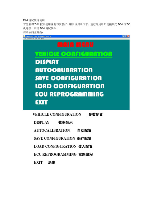
启动后的主界面:VEHICLE CONFIGURATION 参数配置DISPLAY 数据显示AUTOCALIBRATION 自动配置SA VE CONFIGURATION 保存配置LOAD CONFIGURATION 读入配置ECU REPROGRAMMING 重新编程EXIT 退出选择语言,操作如下图:进入VEHICLE CONFIGUNATION 菜单,内部有F1、F2、F3、F4四张表格。
F1表格的内容如下图:Fuel type 燃料类型默认状态:LPG (液化气)选择项:Methane (天然气)Inj. 喷射的方式默认状态:Sequential (顺序喷射)选择项:Full Group (分组喷射)Injectors 喷嘴类型默认状态:Omvl FAST选择项:Omvl STDReducer:减压器类型燃料类型选择为Methane时,就没有此选项默认状态:STD选择项:MP选择项:HPType of revolution signal 转速信号的类型默认状态:Standard选择项:WeakNo. of cylinders 汽缸数默认状态:4 Cylinders选择项:3 CylindersIgnition type 线圈类型默认状态:Two coils选择项:One coil选择项:RPM sensor选择项:RPM sensor2Type of change over 转换类型默认状态:In acceleration选择项:IN DECELERTIONREV. THRESHOLD FOR CHANG-OVER 转换的转速默认状态:1600选择项:800—3000REDUCER TEMPERATURE FOR CHANGE-OVER 转换时的减压器温度默认状态:30CHANG-OVER FROM PETROL-GAS DELAY 转换时的油气延时默认状态:40S选择项:25—250SRESET ECU AND GO TO BASE PARAMETERS 复位ECU到初始状态F2表格内容如下图:TYPE OF LAMBDA PROBE 氧传感器的类型默认状态:0—1VOLT选择项:5—0VOLT选择项:0—5VOLT选择项:0.8—1.6VOLTNUMBER OF AHEAD LAMBDA PROBES 氧传感器的数量默认状态:1选择项:1或2 如果选择2将会出现下一项FUEL TRIM BANK2默认状态为:0选择项:-20—+20TYPE OF MAP SENSOR MAP传感器的类型默认状态:AEB 025选择项:AEB 013TYPE OF GAS LEVEL SENSOR 液为位传感器的类型默认状态:AEB选择项:0—90 OHM选择项:NOT STANDARD 不标准的传感器,可以自己调整里面的数据。
Module 2-1 - HA

VI4 - Mod 2-1 - Slide
11
A note on VMware HA ‘slot’ Calculation
Slot calculation is still done by the vCenter HA service.
It gives the HA service the capacity of the cluster as a whole
Fault tolerance addresses a number of common problematic situations
VI4 - Mod 2-1 - Slide
7
Understanding the Resource Allocation Tab in Clusters
If the host being used to start a virtual machines is in a cluster, you can view information about reserved resources on the Resource Allocation tab for that cluster.
VI4 - Mod 2-1 - Slide 2
Module 2-1 Lessons
Lesson 1 – Overview of High Availability
Lesson 2 – VMware HA Clusters
Lesson 3 – Creating HA Clusters Lesson 4 – Monitoring HA Clusters Lesson 5 – HA Clusters Best Practices Lesson 6 – Troubleshooting VMware HA Lesson 7 – Customizing VMware HA
VWorks Plus软件用户指南说明书

This guide describes VWorks Plus 14.0 or later versions.Software components VWorks Plus consists of OpenLab components and the VWorks software with compliance features.Figure VWorks Plus architecture and primary componentsVWorks software with compliance featuresYou use the VWorks software to manage and control your automation devices. You create labware definitions and liquid classes, set up your devices, create device profiles, and create and run protocols.The VWorks software logs audit trails for records of interest, tracks records by record state (In Development, In Validation, and Released), and performs tamper detection on the records.Components of OpenLab software•Control Panel and Shared Services. An administrator uses the Control Panel to configure Shared Services to control user access to the software, manage software licenses, and manage storage.•Content Management and Content Browser. Shared Services uses a secure storage repository, Content Management, to store records of interest and audit trails. The records are stored in the following location:/VWorks Projects/VWorksNote: Unlike previous VWorks versions, the Windows Registry is not used for storing any records, such as labware definitions and device profiles.A system administrator can use the Content Browser to view and edit theVWorks project structure. The administrator can also edit project contents, for example, if the current version of a VWorks file is corrupted or has beentampered, the administrator can restore a previous version of the file using the Content Browser.ControlPanelShared ServicesVWorkssoftware withcomplianceContentManagementComponents of OpenLab softwareContent BrowserVWorks Plus Quick ReferenceWorkflowWorkflowThe following table provides the overall workflow for VWorks Plus.You can find detailed descriptions of these tasks in the VWorks Knowledge Base. See“Opening VWorks Knowledge Base” on page 8.Note: The VWorks software supports only the roles of VWorks Administrator,Technician, Operator, and Guest. VWorks does not support additional roles that you may create in the Control Panel. For details, see the VWorks Plus Administrator Guide .Step TaskVWorks Role See …1Log in to Control Panel (OpenLab component).Administrator*“Using Control Panel” on page 32Use the Control Panel (OpenLab component) to:•Configure user access. •Manage the software licenses.•Configure storage.AdministratorVWorks PlusAdministrator Guide3Understand VWorks compliance features and configure audit trail options.Administrator“VWorks compliance features” on page 4 and“Setting options for folders and audit trails” on page 44Set up the VWorks software.Administrator or Technician “Setting up VWorks” on page 55Set up your automation devices.Administrator or Technician Device user guide, for example, Bravo Platform User Guide6Create protocols and forms to run your automation devices.Administrator or TechnicianVWorks Automation Control User Guide andVWorks Protocol Authors Quick Guide 7Run a protocol.Administrator,Technician, or Operator “Running a protocol” on page 68Generate audit trail reports.Administrator or Technician “VWorks compliance features” on page 49Perform periodic software and data backups.Administrator or Technician VWorks PlusAdministrator Guide 10View the VWorks project structure in the Content Browser.Administrator“Opening Content Browser” on page 7*VWorks Technicians, Operators, and Guests may log in to Control Panel and change their passwords, but they cannot configure other Control Panel settings.Using Control PanelUsingControl PanelT o use the Control Panel (OpenLab component):1Click the Control Panel icon on the Windows desktop.2Log in using your user name and password. If you cannot log in, contact your administrator.3Under Administration , click the item to display the corresponding page.Administrators only . To add a user, click Users > Create User . To edit a user, click Users , select the user in the Users page, and click Edit User .Note: Non-administrators have only limited access to the Control Panel features. Also, some Control Panel features are not supported in VWorks Plus, such as, Diagnostics and instrument reports.Starting VWorks T o start the VWorks software:1Click the VWorks desktop icon. The VWorks window opens.2Click Log in on the toolbar. The VWorks Login window opens.3Type your VWorks login and password, and then click OK.VWorks compliance featuresVWorks compliancefeatures The following table lists the primary features in the VWorks software that support compliance with Part 11 of Title 21 of the Code of Federal Regulations (21 CFR Part 11). Ensure that you have an understanding of these features and how to use them. For a detailed description, see the VWorks Automation Control Setup Guide.Setting options for folders andaudit trails T o set options for folders and audit trails:In the VWorks window, click T ools > Options. The Options dialog box opens. See the following figure.In the Options dialog box, select or clear the check boxes for the following options:•Restrict file saving to 4th level folders only to support legacy ECM servers.Selected by default. If compatibility with legacy ECM servers is not required and you want to remove this restriction, clear the check box.•Log audit trail for records of interest that are in development state.•Automatically change the state of dependent records.•Prompt user with a list of device profiles when running a protocol in RELEASED state.Feature TaskAudit trails and reports The VWorks software automatically logs audit trails for records of interest (ROI) that are in validation or released states and for records exempt from record states. Released records cannot be changed. Before saving a change to a record that is not yet in the released state, the user must enter an audit comment.To generate an audit trail report for a record of interest, in the VWorks window click T ools > Audit Trail Reports.Record state tracking The states for records of interest are In Development, In Validation, and Released. An administrator or technician can change a record’s state.To change a record state, ensure no records are open In the VWorks window, and then click T ools > Change ROI State.Note: Some records of interest are exempt from state changes, for example, the VWorksOptions.xml file that stores your settings for the VWorks global options.Tamper detection The software verifies data integrity automatically by detecting corrupted records and records that have been modified externally from the VWorks software.You can also run the Tamper Detection command at any time. In the VWorks window,click T ools > Tamper Detection.VWorks activity logs The VWorks software records events that occur during a VWorks session in theMain log, Pipette log, and Time Constraints log. The logs for the current session canbe displayed in the VWorks window. The logs from previous sessions are saved to theContent Management Repository. For details on how to view logs, see the VWorksAutomation Control User Guide.Device activity logs The diagnostics software for each automation device records events that occurduring a diagnostics session. The log for the current session appears in thediagnostics window for the device. These logs are saved in the VWorks Main log.Setting up VWorks For details on audit options, see the VWorks Automation Control Setup Guide. For details on other options, see the VWorks Automation Control User Guide.Setting up VWorks The following table provides a summary of the setup tasks. Only Administrators can migrate or import files from previous VWorks versions. Administrators or Technicians can perform the other setup tasks.Step Task for VWorks Administrator or Technician Where to find instructions1If applicable. Migrate files and registry information from VWorks 12.3,13.0, or 13.1.x into Shared Services storage for use in VWorks Plus.In the VWorks window, click T ools > Migration to open the MigrationWizard.VWorks Automation Control Setup Guide2Use the Labware Editor to create labware definitions for the labware you will use during protocol runs.In the VWorks window, click T ools > Labware Editor to open theLabware Editor.VWorks Automation Control Setup Guide3Bravo Platform only. Use the Liquid Library Editor to specify the pipetting speed and accuracy. CIn the VWorks window, click T ools > Liquid Library Editor to open the Liquid Library Editor and define liquid classes.VWorks Automation Control Setup Guide4Set up your automation devices.See the user guide for thedevice.5Labware storage device only. If you have a Labware MiniHub, set up the Inventory database to manage the labware inventory. VWorks Automation Control Setup Guide6Optional. If you plan to track the protocol parameter settings involved in preparing a microplate for downstream analysis, set up theExperiments database.VWorks Automation Control Setup GuideRunning a protocolNote: You can click in the VWorks window or dialog box to display thecorresponding knowledge base topic for a given setup task.Running a protocol If you are using a VWorks form:Use the controls in the form to set up and run the protocol.If you are running a protocol from the VWorks window:1Click Simulation is on to turn off the simulation mode. The button changes to Simulation is off (figure, item 1).2Click Start (2).T o pause the protocol run:1Click Pause all (3).2In the Scheduler Paused dialog box, select the command to resume, finish processing existing labware already in the system, or abort the run. You can also make device adjustments in the diagnostics software before resuming the run.T o stop the protocol run in an emergency:Press the hardware emergency-stop button. Note that you may not be able to resume a run after an emergency stop.Opening Content BrowserOpening ContentBrowser A user with administrator privileges can open the Content Browser to view and manage the VWorks Project contents in the Content Management Repository. T o start the Content Browser:1Select Start > All apps > Agilent Technologies > Content Browser.2Log in using your user name and your password.3In the Content Browser navigation pane, click Repository > Content > VWorks Projects > VWorks to display the project structure.Opening VWorks context-sensitive helpTo open the help topics in the Content Browser, click the user name in the ContentBrowser banner, and then click Help.The OpenLab Help & Learning page opens.Opening VWorks context-sensitivehelp T o open context-sensitive help in the VWorks window: 1In the VWorks window, click the button on the toolbar. The pointer changes to.2Click an icon or area of interest in the VWorks window. The relevant help topic orguide opens.Opening VWorksKnowledge BaseT o open the knowledge base:•From within the VWorks software, click Help>Knowledge Baseor press F1.•From the Windows desktop, select Start > All apps > Agilent Technologies >VWorks Knowledge Base.ContactingAgilentWeb: https://Contact page: https:///en/contact-us/pageDocumentation feedback: ************************************。
ARIES ARIES-P -Ver.04- 8 0 2 7 9 0 8 1 1 3 7 4 0 产

ISTRUZIONI D'USO E DI INSTALLAZIONE INSTALLATION AND USER'S MANUALINSTRUCTIONS D'UTILISATION ET D'INSTALLATION INSTALLATIONS-UND GEBRAUCHSANLEITUNG INSTRUCCIONES DE USO Y DE INSTALACION INSTRUÇÕES DE USO E DE INSTALAÇÃOCENTRALINA DI COMANDO D811184A ver. 04 08-02-02I CONTROL UNIT GB UNITÉ DE COMMANDE F STEUERZENTRALE D CENTRAL DE MANDO E CENTRAL DO MANDOP ARIES - ARIES P8027908113740a“WARNINGS” leaflet and an “INSTRUCTION MANUAL”.These should both be read carefully as they provide important information about safety, installation, operation and maintenance. This product complies with the recognised technical standards and safety regulations. We declare that this product is in conformity with the following European Directives: 89/336/EEC and 73/23/EEC (and subsequent amendments).1) GENERAL OUTLINEThe ARIES control unit has been designed for swing gates. It can be used for one or two gate controllers.The control unit mod. ARIES P can also be used to perform opening of a single actuator while keeping the other one closed (pedestrian access).2) FUNCTIONSSTOP: In all cases: it stops the gate until a new start command is given.PHOT:Functions can be set with Dip-Switch.Activated during closing.Activated during opening and closing.Rapid closingON: When the position of the gate photocells is exceeded, during both opening and closing, the gate automatically starts to close even if TCA is activated. We recommend setting DIP3 to ON (photocells only activated during closing).Blocks impulsesON: During opening, START commands are not accepted.OFF: During opening, START commands are accepted.PhotocellsON: Photocells only activated during closing.OFF: Photocells activated during opening and closing.Automatic closing time (TCA)ON: Automatic closing activated (can be adjusted from 0 to 90s)Preallarm (mod. ARIES P only)ON: The flashing light turns on abt 3 seconds before the motors start.FOR THE INSTALLER: check the boxes you are interested in.START:four-step logic Gate closedGate openDuring openingDuring closingAfter stop START: two-step logic SCA: Gate open indicating lightit opens it opensit stops and activates TCAit closesit stops and does not activate TCAit starts opening it stops and activats TCA (if activated)it closesit opensit opensoffononflashingATTENTION:Dip non used in mod. ARIES (always in OFF set).3) MAINTENANCE AND DEMOLITIONThe maintenance of the system should only be carried out by qualified personnel regularly. The materials making up the set and its packing must be disposed of according to the regulations in force.Batteries must be properly disposed of.WARNINGSCorrect controller operation is only ensured when the data contained in the present manual are observed. The company is not to be held responsible for any damage resulting from failure to observe the installation standards and the instructions contained in the present manual.The descriptions and illustrations contained in the present manual are not binding. The Company reserves the right to make any alterations deemed appropriate for the technical, manufacturing and commercial improvement of the product, while leaving the essential product features unchanged, at any time and without undertaking to update the present publication.D 811184A _04Thank you for buying this product, our company is sure that you will be more than satisfied with the product ’s performance. The product is supplied with a “WARNINGS ” leaflet and an “INSTRUCTION MANUAL ”.These should both be read carefully as they provide important information about safety, installation, operation and maintenance.This product complies with the recognised technical standards and safety regulations. We declare that this product is in conformity with the following European Directives: 89/336/EEC and 73/23/EEC (and subsequent amendments).1) GENERAL OUTLINEThe ARIES control unit has been designed for swing gates. It can be used for one or two gate controllers.The control unit mod. ARIES P can also be used to perform opening of a single actuator while keeping the other one closed (pedestrian access).2) GENERAL SAFETYWARNING! An incorrect installation or improper use of the product can cause damage to persons, animals or things.•The “Warnings ” leaflet and “Instruction booklet ” supplied with this product should be read carefully as they provide important information about safety, installation, use and maintenance.•Scrap packing materials (plastic, cardboard, polystyrene etc) according to the provisions set out by current standards. Keep nylon or polystyrene bags out of children ’s reach.•Keep the instructions together with the technical brochure for future reference.•This product was exclusively designed and manufactured for the use specified in the present documentation. Any other use not specified in this documentation could damage the product and be dangerous.•The Company declines all responsibility for any consequences resulting from improper use of the product, or use which is different from that expected and specified in the present documentation.•Do not install the product in explosive atmosphere.•The Company declines all responsibility for any consequences resulting from failure to observe Good Technical Practice when constructing closing structures (door, gates etc.), as well as from any deformation which might occur during use.•The installation must comply with the provisions set out by the following European Directives: 89/336/EEC, 73/23/EEC, 98/37/ECC and subsequent amendments.•Disconnect the electrical power supply before carrying out any work on the installation. Also disconnect any buffer batteries, if fitted.•Fit an omnipolar or magnetothermal switch on the mains power supply,having a contact opening distance equal to or greater than 3mm.•Check that a differential switch with a 0.03A threshold is fitted just before the power supply mains.•Check that earthing is carried out correctly: connect all metal parts for closure (doors, gates etc.) and all system components provided with an earth terminal.•The Company declines all responsibility with respect to the automation safety and correct operation when other manufacturers ’ components are used.•Only use original parts for any maintenance or repair operation.•Do not modify the automation components, unless explicitly authorised by the company.•Instruct the product user about the control systems provided and the manual opening operation in case of emergency.•Do not allow persons or children to remain in the automation operation area.•Keep radio control or other control devices out of children ’s reach, in order to avoid unintentional automation activation.•The user must avoid any attempt to carry out work or repair on the automation system, and always request the assistance of qualified personnel.•Anything which is not expressly provided for in the present instructions,is not allowed.3) TECHNICAL SPECIFICATIONSPower supply:...............................................................230V ±10% 50Hz Absorption on empty:.................................................................0.5A max Output power for accessories:..........................................24V~ 6VA max Max relay current:................................................................................8A Max power of motors:...............................................................300 W x 2Torque limiter:.................................................Self-transformer with 4 pos Limit switch:................................................................Adjustable run timePanel dimensions:.........................................................................See fig.1Cabinet protection:............................................................................IP55Working temperature:...............................................................-20 +55°C 4) TERMINAL BOARD CONNECTIONS(Fig.2)CAUTION: Keep the low voltage connections completely separated from the power supply connections.Fig.3 shows the fixing and connection method of the drive condensers whenever they are not fitted to the motor.JP51-2 Single-phase power supply 230V ±10%, 50 Hz (1=L/2=N).For connection to the mains use a multiple-pole cable with a minimum cross section of 3x1.5mm 2 of the type indicated in the above-mentioned standard (by way of example, if the cable is not shielded it must be at least equivalent to H07 RN-F while, if shielded, it must be at least equivalent to H05 VV-F with a cross section of 3x1.5mm 2).JP33-4 (mod.ARIES-P) 230V 40W max. blinker connection.5-6 (mod.ARIES) 230V 40W max. blinker connection.7-8-9 Motor M1 connection - 8 common, 7-9 start.10-11-12 Motor M2(r) connection - 11 common, 10-12 start.JP413-14 Open-close button and key switch (N.O.).13-15 Stop button (N.C.). If unused, leave bridged.13-16 Photocell or pneumatic edge input (N.C.). If unused, leave bridged.17-18 24V 3W max. gate open warning light.18-19 24V~ 0.25A max. (6VA) output (for supplying photocell or other device).20-21 Antenna input for radio-receiver board (20 signal - 21 braid).22 Common terminal (equivalent to terminal 13).23 Terminal for pedestrian control. It moves the leaf of motor M2 connected to terminal 10-11-12. This terminal is available only in ARIES-P control unit.JP225-26 2nd radio channel output of the double-channel receiver board (terminals not fitted on ARIES but fitted on ARIES-P) contact N.O.JP1 Radio-receiver board connector 1-2 channels.5) FUNCTIONSDL1:Power-on LedIt is switched on when the board is electrically powered.START: four-step logic: (DIP5 OFF)gate closed:..................................................................................it opens during opening:............................................... it stops and activates TCA gate open:................................................................................... it closes during closing:.................................... it stops and does not activate TCA after stop:.........................................................................it starts opening START: two-step logic: (DIP5 ON)gate closed:..................................................................................it opens during opening:................................it stops and activats TCA (if activated)gate open:....................................................................................it closes during closing:..............................................................................it opens after stop:.....................................................................................it opens STOP: In all cases: it stops the gate until a new start command is given.PHOT:Functions can be set with DIP-SWITCH.Activated during closing if DIP3-ON.Activated during opening and closing if DIP3-OFF.SCA: Gate open indicating light.with gate closed:...................................................................................off when gate is opening:...........................................................................on with gate open:.......................................................................................on when gate is closing:.....................................................................flashing 6) DIP-SWITCH SELECTION DIP1 Rapid closingON: When the position of the gate photocells is exceeded, during both opening and closing, the gate automatically starts to close even if TCA is activated. We recommend setting DIP3 to ON (photocells only activated during closing).OFF: Function not activated.DIP2 Blocks impulsesON: During opening, START commands are not accepted.OFF: During opening, START commands are accepted.DIP3 PhotocellsON: Photocells only activated during closing.OFF: Photocells activated during opening and closing.D 811184A _04DIP4 Automatic closing time (TCA)ON: Automatic closing activated (can be adjusted from 0 to 90s).OFF: Automatic closing not activated.DIP5 Control logicON: 2-step logic is activated (see start paragraph).OFF: 4-step logic is activated (see start paragraph).DIP6: Preallarm (mod.ARIES P only)ON: The flashing light turns on abt 3 seconds before the motors start.OFF The flashing light turns on simultaneously with the start of the motors.ATTENTION:Dip non used in mod. ARIES (always in OFF set).7) TRIMMER ADJUSTMENTTCA This adjusts the automatic closing time, after which time the gate automatically closes (can be adjusted from 0 to 90s).TW This adjusts the motor working time, after which time the motor stops (can be adjusted from 0 to 40s).TDELAY This adjusts the closing delay time of the second motor (M2).8) MOTOR TORQUE ADJUSTMENTThe ARIES control unit has electric torque adjustment which allows the motor force to be adjusted.The adjustment should be set for the minimum force required to carry out the opening and closing strokes completely.Adjustment is carried out by moving the connection 55 (fig.3) on the tran-sformer sockets as described below:Pos.T1 1st TORQUE (MINIMUM TORQUE)Pos.T2 2nd TORQUE Pos.T3 3rd TORQUEPos.T4 4th TORQUE (MAXIMUM TORQUE)4 motor torque values can be obtained.To gain access to the torque adjustment sockets, disconnect the mains supply and remove the protective case “P ” of the transfomer.CAUTION: Excessive torque adjustment may jeopardise the anti-squash safety function. On the other hand insufficient torque adjustment may not guarantee correct opening or closing strokes.9) MAINTENANCE AND DEMOLITIONThe maintenance of the system should only be carried out by qualified personnel regularly. The materials making up the set and its packing must be disposed of according to the regulations in force.Batteries must be properly disposed of.WARNINGSCorrect controller operation is only ensured when the data contained in the present manual are observed. The company is not to be held responsible for any damage resulting from failure to observe the installation standards and the instructions contained in the present manual.The descriptions and illustrations contained in the present manual are not binding. The Company reserves the right to make any alterations deemed appropriate for the technical, manufacturing and commercial improvement of the product, while leaving the essential product features unchanged, at any time and without undertaking to update the present publication.D811184A_04ARIES/ARIES-P - Ver. 04 -23。
惠普企业发展有限公司VM探索器软件版本6.6发布说明说明书

Legal NoticesWarrantyThe only warranties for Hewlett Packard Enterprise Development LP products and services are set forth in the express warranty statements accompanying such products and services.Nothing herein should be construed as constituting an additional warranty.HPE shall not be liable for technical or editorial errors or omissions contained herein.The information contained herein is subject to change without notice.Restricted Rights LegendConfidential computer software.Valid license from HPE required for possession,use or copying.Consistent with FAR12.211and12.212,Commercial Computer Software,Computer Software Documentation,and Technical Data for Commercial Items are licensed to the ernment under vendor's standard commercial license.Copyright Notice©Copyright2017Hewlett Packard Enterprise Development LPTrademark NoticesAdobe™is a trademark of Adobe Systems Incorporated.Microsoft®and Windows®are U.S.registered trademarks of Microsoft Corporation.UNIX®is a registered trademark of The Open Group.This product includes an interface of the'zlib'general purpose compression library,which is Copyright©1995-2002Jean-loup Gailly and Mark Adler.Documentation updatesThe title page of this document contains the following identifying information:l Software Version number,which indicates the software version.l Document Release Date,which changes each time the document is updated.l Software Release Date,which indicates the release date of this version of the software.To check for recent software updates,go to https:///patches.To verify that you are using the most recent edition of a document,go tohttps:///manuals.This site requires that you register for an HPE Passport and sign in.To register for an HPE Passport ID,go to https:///hppcf/login.do.You will also receive updated or new editions if you subscribe to the appropriate product support service. Contact your HPE sales representative for details.SupportVisit the HPE Software Support Online web site at https://.This web site provides contact information and details about the products,services,and support that HPE Software offers.HPE Software online support provides customer self-solve capabilities.It provides a fast and efficient way to access interactive technical support tools needed to manage your business.As a valued support customer, you can benefit by using the support web site to:l Search for knowledge documents of interestl Submit and track support cases and enhancement requestsl Download software patchesl Access product documentationl Manage support contractsl Look up HPE support contactsl Review information about available servicesl Enter into discussions with other software customersl Research and register for software trainingMost of the support areas require that you register as an HPE Passport user and sign in.Many also require a support contract.To register for an HPE Passport ID,go to https:///hppcf/login.do.To find more information about access levels,go tohttps:///web/softwaresupport/access-levels.ContentsHPE VM Explorer Release Notes5New Features in This Release5 HPE StoreOnce Catalyst File Level Restore5 HPE StoreOnce Catalyst Microsoft Exchange Server Granular Recovery Extension(GRE)5 HPE StoreOnce Catalyst Instant VM Recovery(IVMR)6 Increased size limit for backups to Microsoft Azure6 Microsoft Exchange Server2016CU5support6 New Troubleshooting section in the HPE VM Explorer User Guide6Fixed Defects in This Release6 Obsolescence Plans7HPE VM Explorer Release NotesSoftware version:6.6Publication date:Sept.2017This document is an overview of the changes made to HPE VM Explorer for the6.6release.For more information about which HPE VM Explorer version is best suited to your needs,consult our data sheet, available at https:///h20195/V2/getpdf.aspx/4AA6-4147ENW.pdf.New Features in This ReleaseHPE VM Explorer6.6further extends the features of the HPE StoreOnce Catalyst integration,as well as other enhancements and bug fixes.The enhancements in HPE VM Explorer6.6include:l HPE StoreOnce Catalyst File Level Restore,belowl HPE StoreOnce Catalyst Microsoft Exchange Server Granular Recovery Extension(GRE),below l HPE StoreOnce Catalyst Instant VM Recovery(IVMR),on the next pagel Increased size limit for backups to Microsoft Azure,on the next pagel Microsoft Exchange Server2016CU5support,on the next pagel New Troubleshooting section in the HPE VM Explorer User Guide,on the next pageHPE StoreOnce Catalyst File Level RestoreAs of HPE VM Explorer6.6,you can now browse a disk image file and recover the desired individual file(s)or directories from an HPE StoreOnce Catalyst backup.Simply select the desired disk image file to navigate through its content and view its files structure in Management>File Explorer.To perform a file level restore from HPE StoreOnce Catalyst,select the desired file(s)and/or directories(keep the Ctrl key on your keyboard pressed for multiple files and directories),right-click and select Download on the shortcut menu.HPE StoreOnce Catalyst Microsoft Exchange Server Granular Recovery Extension(GRE)HPE VM Explorer6.6has extended the Microsoft Exchange Server Granular Recovery Extension to the HPE StoreOnce Catalyst storage target.You can now recover e-mails(with or without attachments)from a VM backup that contains a valid Microsoft Exchange Server backup stored on anHPE StoreOnce Catalyst store.Just like in the case of Exchange Server VMs stored on other environments,this feature applies to the Enterprise Edition of HPE VM Explorer.HPE StoreOnce Catalyst Instant VM Recovery(IVMR)The Instant VM Recovery feature has been extended to support VM backups on HPE StoreOnce Catalyst stores.The procedure is identical to the instant recovery of a VM from other storage targets. This feature is only available for VMware VMs backed up on an HPE StoreOnce Catalyst store. Increased size limit for backups to Microsoft AzureThe maximum backup size to Microsoft Azure has been increased to match the latest developments from Microsoft.You can now perform backup&restore operations of up to4.7terabytes per file when using Microsoft Azure.Microsoft Exchange Server2016CU5supportMicrosoft Exchange Server2016version CU5is now supported with HPE VM Explorer6.6. New Troubleshooting section in the HPE VM Explorer User GuideThe User Guide documentation now features a new Troubleshooting section,designed to help you address some of the issues you may encounter.We recommend that you become familiar with the information in the Troubleshooting section before escalating any issues you might have to Support. Fixed Defects in This ReleaseThe following defects have been resolved in the HPE VM Explorer6.6release.For more information about fixed defects,visit HPE Software Support Online,or contact your HPE Support representative directly.Title:Microsoft Exchange Server2013error when opening a databaseDescription:An issue occurred when opening a Microsoft Exchange Server database in German,with the error“The given key was not in the dictionary”.The event log displayed"Unexpected error while parsing for MapiTags(blob version3):Unknown blob segment type:0000".Title:Unrecognized German characters in Hyper-VDescription:An issue occurred when the path to a Hyper-V VM server in German language contained unrecognized characters.Title:Blank space at the end of a VM name returned an errorDescription:HPE VM Explorer did not manage to perform a standard/incremental backup of a VM the name of which contained a blank space at the end.Title:Transfer size and transfer rate inaccurately displayedDescription:When performing a scheduled backup,the data size and data transfer rate were not displayed accurately in the Scheduled Task view.Title:Clone command without the HPE VM Explorer Agent enabled on an ESXi server Description:An issue occurred when HPE VM Explorer was trying to perform a clone command while the HPE VM Explorer Agent was disabled on an ESXi server.Clone commands are not available when the HPE VM Explorer Agent is not enabled.Obsolescence PlansTo keep up to date with HPE VM Explorer obsolescence plans,visithttps:///web/softwaresupport/document/-/facetsearch/document/KM02739516.。
- 1、下载文档前请自行甄别文档内容的完整性,平台不提供额外的编辑、内容补充、找答案等附加服务。
- 2、"仅部分预览"的文档,不可在线预览部分如存在完整性等问题,可反馈申请退款(可完整预览的文档不适用该条件!)。
- 3、如文档侵犯您的权益,请联系客服反馈,我们会尽快为您处理(人工客服工作时间:9:00-18:30)。
•
Approach based on Information Systems (check the Bullwhip Effect), not an integrated approach to both Materials and Information Flow across the totality of the supply chain.
7
Definition of Logistic Loops
MTO: Make To Order, the product does not exist in the FP Warehouse when the Order is entered. The Production Order is started and the customer has to wait the production Lead-time. The Picking Cycle can only start after receipt in FP Warehouse. Usually the Picking is simplified because the Product is Customer specific and can be stored in a customer Bin in the FPW. PTO=: Pick To Order, the product exists in the FP Warehouse when the Order is entered. The Picking cycle can start immediately
• Demand and Leadtime Variation; • Total Pull Planning; • Total Flow Management Targets and Results.
1
Introduction
• After applying Pull Planning in internal logistics, Total Pull Planning is the extension of this model to all Logistic Loops of a Supply Chain;
7 2 4 3 7 3
6
5
2
1
1 2 3 4
Outsourcing or hiring by request Flow meter (production data) Just in Case stock Bottleneck
5 6 7 8
Former production line (shut down) Rework loop Muda, Losses
20%
Tempo
• Most of the ERP systems are modeled with rules that increase this effect;
Procura
• Only Pull Planning and Leveling can strongly reduce this effect.
Consumer
Procura
5%
• This phenomena is the main direct cause of Muda of Stock and Muda of Excess Production;
• Causes:
• Order Grouping to increase lot size (low leveling); • Using data from the immediate customer, instead of data from the final customer; • Excessive reaction to small changes in demand (safety non standardized stock building);
Pull Planning is based on:
MRP stock and push
Order forecast and real Orders
Physical supermarkets
Real orders and stock replenishment
High safety stock
Quantity unreliablebased on MRP figures
• Bringing a breakthrough in Inventory reduction; • Achieving 100% OTD – On Time Delivery; • Enabling big increases of Productivity in Production and Logistics.
Raw Materia Supplier
40%
Tempo
6
The Bullwhip Effect: weekly production vs. weekly customer delivery
PRODUCED 2 500
DELIVERED
2 000
Stockouts
capacity loading
Buying Decision Process Scheduling and Order Release
Receive, Check, Move to Picking Point
Picking, Packing, Dispatch
Receive, Check, Move to Picking Point
Orders Entry Customer Order
Production Order Requirements
Picking Order Requirements
Scheduling and Order Release
MTS: Make To Stock, a Production Requirement Algorithm plans the Production in advance, responding to a consumption sign (BTR, reorder point type).
Plant
Supply Chain MRP / DRP
Suppliers
Wholesalers
Distributors
Retailers
3
Supply Chain Traditional Operations Planning
Traditional Supply Chain is based on:
2
Supply Chain Traditional Operations Planning
• Traditional Supply Chain tools “appeared” in the 90´ s to answer the following question:
– How to deliver the required products in the shortest delay possible at a level of 100% customer service, minimizing at the same time the overall stock of the complete logistics chain
• Introduction;
• Supply Chain Traditional Operations Planning;
• Muda Elimination is Needed in the Supply Chain; • A Main Cause of Muda: The Bullwhip Effect; • Definition of Logistic Loops;
External Transport
Customer Warehouse
Production
Distribution
8
Definition of Logistic Loops
Logistic Loop 2: - Production to Order (MTO strategy), or; - Build To Replenish (E-Kanban, MTS strategy)
• Supply Chain Seen as a Chain of Logistic Loops;
• What is a Pull Planning Loop; • How to avoid the Bullwhip Effect; • Kaizen Pull Planning;
• A Pull Algorithm For MTS and MTO;
IV. 5. Total Pull Planning
IV. External Logistics Flow
5. Total Pull Planning 4. Outbound and Delivering 3. Inbound and Sourcing 2. Milkrun 1. Warehouse Design
5
A Main Cause of Muda: The Bullwhip Effect
• Small changes in the Final Customer Demand will generate demand increases in every step of the Supply Chain;
Picking, Packing, Dispatch
Receive, Check, Move to Picking Point
Picking, Packing, Dispatch
Production Internal Transport Supplier Materials Warehouse Internal Transport Supplier Finished Product Warehouse