VC0706串口工具说明文档
USB串行转换器说明书
USB Serial Converter USB Serial Converter20116.0520Rev. 1.0.0.000Rev. 11Contents1.1.Introduction Introduction (2)1-1. Overview.............................................................................. 2 1-2. Package Contents................................................................ 2 1-3. System Requirements and Restrictions.............................. 2 1-4. DB9(RS-232C) connector Pin Assignment..........................32.I nstallation on nstallation on Windows PC Windows PC (4)2-1. Installation on Windows 10/8.1/8/7/VistaServer2012 R2/Server2012/Server2008 R2/Server2008........ 4 2-2. Confirmation........................................................................ 8 2-3. Uninstallation on Windows 10/8.1/8/7/VistaServer2012 R2/Server2012/Server2008 R2/Server2008 (9)3. . Sp Sp Specification ecification ecifications s (11)*All trademarks and logos are the properties of their respective holders. *The specifications and pictures are subject to change without notice.21.1.Introduction Introduction Introduction1-1.1. Overview Overview Overview● REX-USB60F is a USB to serial converter.Compatible with Universal Serial Bus specifications Rev. 1.1. ● Up to 230.4Kbps data transfer rate. ● Standard USB (A type Male) Easy to connect PC.●Virtual COM port driverREX-USB60F can be used with FTDI’s VCP drivers to provide a COM port on a PC.●LED indicatorsREX-USB60F has “PWR/TXD/RXD” LED indicators for monitoring communication status.PWR: power / TXD: transmit / RXD: receive1-2. Package C Package Contents ontents ontentsThis product is shipped with the following items: ● REX-USB60F USB Serial Converter ● Setup CD-ROM. ● Installation Guide● Warranty Card in Japanese1-3. System Requirements and Restrictions System Requirements and RestrictionsHost machine●Windows PC with free Standard USB A type portOperating System● Windows 10, Windows 8.1, Windows 8, Windows7, Windows Vista● Windows Server 2012 R2, Windows Server 2012, Windows Server 2008 R2, Windows Server 200831-4. DB9(DB9(RS RS RS--232C 232C)) connector connector Pin Assignment Pin Assignment Pin AssignmentThe pin assignment of the connector is below:This DB9pin connector is compatible with ANSI/EIA/TIA-574 specifications.Signal Name Name Direction Direction DTE DTE – DCE. DCE.Meaning Meaning1 DCD <--- Data Carrier Detected2 RXD <--- Received Data3 TXD ---> Transmitted Data4 DTR ---> Data Terminal Ready5 GND - Signal Ground6 DSR <--- Data Set Ready7 RTS ---> Request to Send8 CTS <--- Clear to Send 9RI<---Ring Indicator1 2 3 4 56 7 8 942. Installation Installation on on on Windows PC Windows PC Windows PCPlease make sure that the Windows PC meets the following specifications: • USB port is Standard-USB A • Windows version is Vista or later2-1.1. Installation Installation on Windows 10/8.1/8/7/Vista/on Windows 10/8.1/8/7/Vista/on Windows 10/8.1/8/7/Vista/Server 2012Server 2012 R2/Server2012R2/Server2012/Server 2008 R2/ Server 2008/Server 2008 R2/ Server 2008/Server 2008 R2/ Server 2008Before connecting the REX-USB60F USB serial converter to a USB port, follow the instructions below:1) Insert the setup CD-ROM for the REX-USB60F into your CD-ROM drive. Navigate to the [Setup] folder on the CD that contains the USB60F_Setup.exe Double click USB60F_Setup.exe.2) A “User Account Control” dialog box may appear. Click [Yes] to proceed with the installation.3) The InstallShield Wizard for RATOC REX-USB60F Installer will start. Click [Next] to proceed with the installation.4) A “RATOC REX-USB60F Installer“ will start.Click [Install] to proceed with the installation.55) A “Windows Security” dialog box will appear.Click [Install] to proceed with the installation.6) A “Windows Security” dialog box will appear again. Click [Install] to proceed with the installation.67) The screen will automatically complete and then change to the one below:Click [Finish]. The “RATOC REX-USB60F Installer” has finished. Connect the REX-USB60F to a spare USB port on your PC.The necessary drivers will be found.It will start installation and automatically finish.Proceed to (2-2) Confirmation of setting REX-USB60F to confirm the installation has finished properly.72-2.ConfirmationConfirmationFor confirming the installation has finished properly.Open the Device Manager and select “View > Devices by Connection”. Under the “Ports(COM/LPT)”category, the label “USB Serial Port” with an additional COM port will appear.If the label “USB Serial Port” shows without yellow “!” mark, the installation is done properly.892-3. Uninstallation on Wind Uninstallation on Windo o ws 10/8.1/8/7/Vista ws 10/8.1/8/7/Vista Server 2012Server 2012 R2/R2/Server 2012/S Server 2012/S Server 2012/Server 2008erver 2008erver 2008 R2/Server 2008R2/Server 2008Open the [Program and function] at the [Control Panel].Select the [RATOC REX-USB60F Installer] and click [Uninstall].The InstallShield Wizard for RATOC REX-USB60F Installer will start.The following dialog will appear. Click [Yes] to proceed with the uninstallation.The screen will automatically complete and then change to the one below:Click [Finish] to finish with the uninstallation.103. SpecificationSpecifications sProduct Name REX-USB60FSerial Input/Output level RS-232C levelUSB Specification USB(Universal Serial Bus) Specifications Rev. 1.1 Connector USB :Standard-USB Type A maleRS-232C:D-Sub9 male (with anchor [#4-40]) Number of I/O ports 1 portUnit Dimensions 3.35[L] x 1.1[W] x 0.43[H] in (85[L] x 28[W] x 11[H] mm) Cable Length Approx. 2.83 ft (85 cm)Weight 0.194 oz (55 g)Data transfer mode Asynchronous (Start stop synchronization)Data transfer Rate (Baud) 300/600/1,200/2,400/4,800/9,600/19,200/38,40057,600/115,200/230,400 bpsTransmit Distance Within 50ft (15m)Power Voltage DC+5V (Powered for USB Bus)Power Consumption Average: 36mA(5V) Max.: 60mA(5V)Serial Parameter Data bit: 7/8 Start bit:1 Stop bit: 1/2Parity bit: even/odd/noneRS-232C connector D-SUB9PIN RS-232C connector MaleANSI/EIA/TIA-574LED Indicators PWR:Power LEDIf 5V power from USB bus is properly suppliedfrom USB bus, this indicator LED will be on.TXD:Transmit data indicator (Host to Device)RXD:Receive data indicator (Device to Host) Operating Environment Temperature: 32ºF to 122ºF (0ºC to 50ºC)Humidity: 10 to 90% (non condensing)Storage Environment Temperature: -4ºF to 149ºF (-20ºC to 65ºC)Humidity: 10 to 90%(non condensing)Note:1.Do not remove while the application is communicating. System will beunstable.2.Do not operate to suspend while the application is communicating.System will be unable to resume properly.3.This product does not support the serial mouse for connecting to RS-232Cport.1112。
串口调试助手vc源程序及其详细编写过程

串口调试助手vc源程序及其详细编写过程1.建立项目2.在项目中插入MSComm控件3.利用ClassWizard定义CMSComm类控制变量4.在对话框中添加控件5.添加串口事件消息处理函数OnComm()6.打开和设置串口参数7.发送数据8.发送十六进制字符9.在接收框中以十六进制显示10.如何设置自动发送11.什么是VARIANT数据类型?如何使用VARIANT数据类型?1.建立项目:打开VC++6.0,建立一个基于对话框的MFC应用程序SCommTest(与我源代码一致,等会你会方便一点);2.在项目中插入MSComm控件选择Project菜单下Add To Project子菜单中的Components and Controls…选项,在弹出的对话框中双击Registered ActiveX Controls项(稍等一会,这个过程较慢),则所有注册过的ActiveX控件出现在列表框中。
选择Microsoft Communications Control, version 6.0,,单击Insert按钮将它插入到我们的Project中来,接受缺省的选项。
(如果你在控件列表中看不到Microsoft Communications Control, version 6.0,那可能是你在安装VC6时没有把ActiveX一项选上,重新安装VC6,选上ActiveX就可以了),这时在ClassView视窗中就可以看到CMSComm类了,(注意:此类在ClassWizard中看不到,重构clw文件也一样),并且在控件工具栏Controls中出现了电话图标(如图1所示),现在要做的是用鼠标将此图标拖到对话框中,程序运行后,这个图标是看不到的。
3.利用ClassWizard定义CMSComm类控制对象打开ClassWizard->Member Viariables选项卡,选择CSCommTestDlg类,为IDC_MSCOMM1添加控制变量:m_ctrlComm,这时你可以看一看,在对话框头文件中自动加入了//{{AFX_INCLUDES() #i nclude "mscomm.h" //}}AFX_INCLUDES (这时运行程序,如果有错,那就再从头开始)。
串口编程指令手册.pdf

5. 设置语法
命令信息允许设置多个命令。每个命令用分号结束,但注意字符串用双引号给出 的分号必须跟在双引号后面。
命令的结构为:”nls”或者”NLS” + 命令序列 (+ 等号 + 设置信息) 具体的设置命令列表见下节。 设置的命令有 4 中形式:
5.1. 设置语法 1: 命令
这一形式的命令最多,就是不要借助数据码,一次设置就可以完成的设置命令。
综合设置............................................................. 9 通讯设置............................................................ 10 硬件设置............................................................ 11 数据格式设置........................................................ 11 解码模式设置........................................................ 12 一维条码设置........................................................ 13 二维条码设置........................................................ 15 OCR 设置 ............................................................ 16
目录
1. 简介 .................................................................. 1 2. 读者 .................................................................. 1 3. 约定 .................................................................. 1
微机(Microchip)EV96C70A 55W双输出转换器操作手册说明书

EV96C70A 55W Dual Output Converter from 36V–54V Input EVB IntroductionThis document provides the description and operating procedures for Microchip's dual output 55V/30W and 5V/25W board from 36V–54V input EV96C70A. This board type is used for evaluating the performance of Microchip PoE systems and the Microchip PWM controller LX7309, which is an integral part of Microchip PoE PD controllersPD70201 and PD70211.Microchip’s PD70201 and PD70211 devices are a part of a family of devices that support the IEEE® 802.3af, IEEE 802.3at, and HDBaseT standards PD interface.The PD interface includes the following family of devices.Table 1. Microchip Powered Device Products OfferingsMicrochip’s EV96C70A evaluation board provides designers with the environment needed for evaluating the performance and implementation of PoE PD applications.The board uses two PWM LX7309, which are an integral part of Microchip PD controllers PD70201 and PD70211. This document provides all necessary procedures and instructions to install and operate this board.Figure 1. EV96C70A Block DiagramThe board can be powered through an input connector J6 by a lab supply or by an output of PoE PD front end. See section 1.3. Electrical Characteristics for the input voltage range. The external load is connected to the evaluation board using the J1 (5V/25W) and J7 (55V/30W) output connectors. The following figure shows the location of input and output connectors.D5 is the 55V indication LED and D9 is the 5V indication LED. These LEDs indicate the presence of the corresponding outputs.The following figure shows a top view of the evaluation board.Figure 2. EV96C70A Evaluation BoardTable of Contents Introduction (1)1. Product Overview (4)1.1. Evaluation Board Features (4)1.2. Evaluation Board Connectors (4)1.3. Electrical Characteristics (5)2. Installation (6)2.1. Initial Configuration (6)3. Schematic (7)4. Bill of Materials (9)5. Board Layout (16)6. Ordering Information (20)7. Revision History (21)The Microchip Website (22)Product Change Notification Service (22)Customer Support (22)Microchip Devices Code Protection Feature (22)Legal Notice (22)Trademarks (23)Quality Management System (24)Worldwide Sales and Service (25)1. Product OverviewThis section provides the product overview of the evaluation board.1.1 Evaluation Board Features•Input DC voltage connector and two output voltage connectors.•Onboard “output present” LED indicators.•36 V DC to 54 V DC input voltage range.•Evaluation board working temperature: 0 ℃ to 70 ℃.•RoHS compliant.1.2 Evaluation Board ConnectorsThe following table lists the evaluation board connectors.Table 1-1. Connector Details1.2.1 Input ConnectorThe following table lists pinout of input connector.Table 1-2. J1 Connector•Manufacturer: On Shore Technology.•Manufacturer part number: ED700/2.1.2.2 Output ConnectorsAn external load is connected to the evaluation board using the J1 and J7 output connectors. The following tables list pinouts of the output connector.The manufacturer and manufacturer part number details of the J1 and J7 output connectors are as follows:•Manufacturer: Kaifeng Electronic.•Manufacturer part number: KF350V-02P-14.Table 1-3. J1 ConnectorTable 1-4. J7 Connector1.3 Electrical CharacteristicsThe following table lists the electrical characteristics of the EV96C70A evaluation board.Table 1-5. Electrical CharacteristicsInstallation 2. InstallationThis section provides information about the installation procedure of the EV96C70A evaluation board.Note: Ensure that power source of the board is turned OFF before all peripheral devices are connected.2.1 Initial ConfigurationPerform the following steps for initial configuration:1.Connect load to the board (using J1 and J7).2.Connect a DC supply to input connector J6.3.Turn ON the DC supply.Schematic 3.l4. Bill of MaterialsThe following table lists the bill of materials.Table 4-1. Bill of MaterialsNote: Third-party components can be replaced by approved equivalents. N.C = not installed (optional).5. Board LayoutThis section describes the layout of the evaluation board. This is a four-layer board with 2 Oz copper. The following figures show the silk of the board for tracking devices placements.Figure 5-1. Top SilkFigure 5-4. Bottom CopperOrdering Information 6. Ordering InformationThe following table lists the evaluation board ordering information.Table 6-1. Evaluation Board Ordering InformationRevision History 7. Revision HistoryThe Microchip WebsiteMicrochip provides online support via our website at /. This website is used to make files and information easily available to customers. Some of the content available includes:•Product Support – Data sheets and errata, application notes and sample programs, design resources, user’s guides and hardware support documents, latest software releases and archived software•General Technical Support – Frequently Asked Questions (FAQs), technical support requests, online discussion groups, Microchip design partner program member listing•Business of Microchip – Product selector and ordering guides, latest Microchip press releases, listing of seminars and events, listings of Microchip sales offices, distributors and factory representativesProduct Change Notification ServiceMicrochip’s product change notification service helps keep customers current on Microchip products. Subscribers will receive email notification whenever there are changes, updates, revisions or errata related to a specified product family or development tool of interest.To register, go to /pcn and follow the registration instructions.Customer SupportUsers of Microchip products can receive assistance through several channels:•Distributor or Representative•Local Sales Office•Embedded Solutions Engineer (ESE)•Technical SupportCustomers should contact their distributor, representative or ESE for support. Local sales offices are also available to help customers. A listing of sales offices and locations is included in this document.Technical support is available through the website at: /supportMicrochip Devices Code Protection FeatureNote the following details of the code protection feature on Microchip products:•Microchip products meet the specifications contained in their particular Microchip Data Sheet.•Microchip believes that its family of products is secure when used in the intended manner, within operating specifications, and under normal conditions.•Microchip values and aggressively protects its intellectual property rights. Attempts to breach the code protection features of Microchip product is strictly prohibited and may violate the Digital Millennium Copyright Act.•Neither Microchip nor any other semiconductor manufacturer can guarantee the security of its code. Code protection does not mean that we are guaranteeing the product is “unbreakable”. Code protection is constantly evolving. Microchip is committed to continuously improving the code protection features of our products. Legal NoticeThis publication and the information herein may be used only with Microchip products, including to design, test,and integrate Microchip products with your application. Use of this information in any other manner violates these terms. Information regarding device applications is provided only for your convenience and may be supersededby updates. It is your responsibility to ensure that your application meets with your specifications. Contact yourlocal Microchip sales office for additional support or, obtain additional support at /en-us/support/ design-help/client-support-services.THIS INFORMATION IS PROVIDED BY MICROCHIP "AS IS". MICROCHIP MAKES NO REPRESENTATIONSOR WARRANTIES OF ANY KIND WHETHER EXPRESS OR IMPLIED, WRITTEN OR ORAL, STATUTORYOR OTHERWISE, RELATED TO THE INFORMATION INCLUDING BUT NOT LIMITED TO ANY IMPLIED WARRANTIES OF NON-INFRINGEMENT, MERCHANTABILITY, AND FITNESS FOR A PARTICULAR PURPOSE, OR WARRANTIES RELATED TO ITS CONDITION, QUALITY, OR PERFORMANCE.IN NO EVENT WILL MICROCHIP BE LIABLE FOR ANY INDIRECT, SPECIAL, PUNITIVE, INCIDENTAL, OR CONSEQUENTIAL LOSS, DAMAGE, COST, OR EXPENSE OF ANY KIND WHATSOEVER RELATED TO THE INFORMATION OR ITS USE, HOWEVER CAUSED, EVEN IF MICROCHIP HAS BEEN ADVISED OF THE POSSIBILITY OR THE DAMAGES ARE FORESEEABLE. TO THE FULLEST EXTENT ALLOWED BY LAW, MICROCHIP'S TOTAL LIABILITY ON ALL CLAIMS IN ANY WAY RELATED TO THE INFORMATION OR ITS USE WILL NOT EXCEED THE AMOUNT OF FEES, IF ANY, THAT YOU HAVE PAID DIRECTLY TO MICROCHIP FOR THE INFORMATION.Use of Microchip devices in life support and/or safety applications is entirely at the buyer's risk, and the buyer agrees to defend, indemnify and hold harmless Microchip from any and all damages, claims, suits, or expenses resulting from such use. No licenses are conveyed, implicitly or otherwise, under any Microchip intellectual property rights unless otherwise stated.TrademarksThe Microchip name and logo, the Microchip logo, Adaptec, AnyRate, AVR, AVR logo, AVR Freaks, BesTime, BitCloud, CryptoMemory, CryptoRF, dsPIC, flexPWR, HELDO, IGLOO, JukeBlox, KeeLoq, Kleer, LANCheck, LinkMD, maXStylus, maXTouch, MediaLB, megaAVR, Microsemi, Microsemi logo, MOST, MOST logo, MPLAB, OptoLyzer, PIC, picoPower, PICSTART, PIC32 logo, PolarFire, Prochip Designer, QTouch, SAM-BA, SenGenuity, SpyNIC, SST, SST Logo, SuperFlash, Symmetricom, SyncServer, Tachyon, TimeSource, tinyAVR, UNI/O, Vectron, and XMEGA are registered trademarks of Microchip Technology Incorporated in the U.S.A. and other countries. AgileSwitch, APT, ClockWorks, The Embedded Control Solutions Company, EtherSynch, Flashtec, Hyper Speed Control, HyperLight Load, IntelliMOS, Libero, motorBench, mTouch, Powermite 3, Precision Edge, ProASIC, ProASIC Plus, ProASIC Plus logo, Quiet- Wire, SmartFusion, SyncWorld, Temux, TimeCesium, TimeHub, TimePictra, TimeProvider, TrueTime, WinPath, and ZL are registered trademarks of Microchip Technology Incorporated in the U.S.A.Adjacent Key Suppression, AKS, Analog-for-the-Digital Age, Any Capacitor, AnyIn, AnyOut, Augmented Switching, BlueSky, BodyCom, CodeGuard, CryptoAuthentication, CryptoAutomotive, CryptoCompanion, CryptoController, dsPICDEM, , Dynamic Average Matching, DAM, ECAN, Espresso T1S, EtherGREEN, GridTime, IdealBridge, In-Circuit Serial Programming, ICSP, INICnet, Intelligent Paralleling, Inter-Chip Connectivity, JitterBlocker, Knob-on-Display, maxCrypto, maxView, memBrain, Mindi, MiWi, MPASM, MPF, MPLAB Certified logo, MPLIB, MPLINK, MultiTRAK, NetDetach, NVM Express, NVMe, Omniscient Code Generation, PICDEM, , PICkit, PICtail, PowerSmart, PureSilicon, QMatrix, REAL ICE, Ripple Blocker, RTAX, RTG4, SAM-ICE, Serial Quad I/O, simpleMAP, SimpliPHY, SmartBuffer, SmartHLS, SMART-I.S., storClad, SQI, SuperSwitcher, SuperSwitcher II, Switchtec, SynchroPHY, Total Endurance, TSHARC, USBCheck, VariSense, VectorBlox, VeriPHY, ViewSpan, WiperLock, XpressConnect, and ZENA are trademarks of Microchip Technology Incorporated in theU.S.A. and other countries.SQTP is a service mark of Microchip Technology Incorporated in the U.S.A.The Adaptec logo, Frequency on Demand, Silicon Storage Technology, Symmcom, and Trusted Time are registered trademarks of Microchip Technology Inc. in other countries.GestIC is a registered trademark of Microchip Technology Germany II GmbH & Co. KG, a subsidiary of Microchip Technology Inc., in other countries.All other trademarks mentioned herein are property of their respective companies.© 2022, Microchip Technology Incorporated and its subsidiaries. All Rights Reserved.ISBN: 978-1-5224-9978-7Quality Management SystemFor information regarding Microchip’s Quality Management Systems, please visit /quality.Worldwide Sales and Service。
PG0703P_C02A 等产品的编程手册说明书
目录1. 远程控制概述 (1)1.1 如何远程控制 (1)1.2 通信协议 (3)1.3 远程控制功能 (5)2. SCPI简介 (10)2.1 命令格式 (10)2.2 符号说明 (10)2.3 参数类型 (11)2.4 命令缩写 (12)3. 模式共用命令 (13)3.1 IEEE公用命令子系统 (13)3.2 系统命令 (15)3.3 存储命令 (20)3.4 显示控制 (21)3.5 模式命令 (22)3.6 扫描命令 (22)4. 频谱分析模式 (24)4.1 仪器模式命令 (24)4.2 Initiate命令子系统 (24)4.3 Sense命令子系统 (25)4.4 Calculate命令系统 (43)4.5 Measurement命令系统 (58)4.6 触发 (72)4.7 TG (73)4.8 调制解调 (75)5. 矢量网络分析模式 (77)5.1 频率控制 (77)5.2 幅度控制 (78)5.3 带宽控制 (80)5.4 扫描控制 (80)5.5 TG (81)5.6 迹线 (81)5.7 光标 (85)6. 故障定点分析模式 (98)6.1 频率控制 (98)6.2 幅度控制 (99)6.3 扫描控制 (100)6.4 迹线 (101)6.5 光标 (102)6.6 测量 (105)7. 调制分析模式 (110)7.1 频率控制 (110)7.2 幅度控制 (111)7.3 带宽控制 (112)7.4 扫描控制 (113)7.5 迹线 (114)7.6 光标 (117)7.7 测量 (119)7.8 触发 (124)8. 实时频谱分析模式 (126)8.1 频率控制 (126)8.2 幅度控制 (129)8.3 带宽控制 (131)8.4 扫描控制 (132)8.5 迹线 (134)8.6 光标 (137)8.7 触发 (139)8.8 测量 (142)9. EMI测量 (145)9.1 频率控制 (145)9.2 幅度控制 (147)9.3 带宽控制 (150)9.4 扫描控制 (151)9.5 迹线 (153)9.6 光标 (155)9.7 限制 (159)10. 编程示例 (168)10.1 使用VISA的编程示例 (168)10.2Sockets/Telnet示例 (182)SIGLENT 1. 远程控制概述分析仪支持通过USB、LAN、GPIB-USB接口与计算机进行通信。
Corebai微处理器监控电路操作手册说明书
产品特点●修正供电电压监控器2.63V(CBM706P,CBM706R,CBM708R)2.93V(CBM706S,CBM708S)3.08V(CBM706T,CBM708T)●100µA静态电流●200ms复位脉冲宽度●防抖手动复位输入(MR)●独立看门狗定时器● 1.6秒超时(CBM706P,CBM706R,CBM706S,CBM706T)●电源故障或低电量警告的电压监测●VCC=1V时确保复位有效信号●CBM706P/R/S/T,CBM708R/S/T更好的升级能力产品应用●微型处理器系统●计算器●控制器●智能仪器●关键微处理器监控●电源操作系统●便携仪器产品描述CBM706P、CBM706R、CBM706S、CBM706T和CBM708R、CBM708S、CBM708T系列微处理器监控电路适用于3V或3.3V电压监控。
CBM706P、CBM706R、CBM706S、CBM706T系列产品提供有源监控电路,该监控电路能够在电源开启、电源关闭以及电压不足的条件下产生复位输出。
这个复位输出能够在低至1V的供电电源下保持工作。
该系列产品还提供独立看门狗监控电路。
如果看门狗输入能够在1.6秒内没有触发的情况下激活。
此外,还为电源故障警报、低电压检测或附加电源装置提供1.25V的临界值检测器,还包括有效低电平防抖动的手动复位输入。
CBM706R,CBM706S,and CBM706T产品除监视电平的复位阀值外与上述产品功能一致,复位阀值分别为2.63V,2.93V,3.08V。
CBM706P与CBM706R的复位阀值都是2.63V。
唯一不同的是CBM706P 具有自动高复位输出。
CBM708R/CBM708S/CBM708T提供类似CBM706R/CBM706S/CBM706T的功能,唯一不同的是不提供看门狗定时,除提供有效低电平复位输出外还提供有效高电平复位输出代替看门狗定时功能。
所有产品均采用8脚MSOP和8脚SOP封装。
串口调试助手设计思路与手册
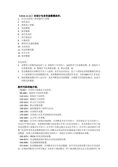
(2016-11-21)本设计包含的函数模块有:1.打开/关闭串口和设置串口参数2.软件退出3.获取串口参数4.发送数据5.接受数据6.清空发送区7.清空接收区8.计数清零9.暂停/开启接收数据10.自动发送11.发送周期设置12.打开文件13.保存数据补充说明:1.设置串口参数里面包括了1)获取串口可用串口。
2)波特率下拉参数设置。
3)校验位下拉参数设置。
4)数据位下拉参数设置。
5)默认设置。
6)2.发送数据前先判断是否为十六进制,是否为自动发送。
是十六进制发送则把数据先转为十六进制格式并获取数据长度,再把数据转到发送缓冲区发送,否则ASCII码文本发送3.接收数据函数在串口运行时一直在判断是否有新数据,并根据不同的接收模式,加显不同格式的数据软件代码详细介绍:(74-92h)可用串口检测及下拉控件。
(96-109h)波特率下拉控件设置。
(113-121h)校验位下拉控件。
(125-131h)数据位下拉控件。
(135-141h)停止位下拉控件。
(145-155h)默认参数设置。
(159-162h)接收数据串口说明与启动。
(168-174h)关闭软件设置。
(176-180h)关闭窗口后先关闭线程再关闭进程。
(182-194h)定义串口各参数。
(197-281h)打开串口按钮回调函数,先判断是否有可用串口,没有则显示“无可用串口,无法打开”然后返回,有则继续判断当前是要打开串口还是关闭串口,若是需要打开串口则尝试设置串口参数并打开串口,打开串口失败会提示无法打开串口,打开串口成功则串口参数下拉控件变灰发送数据按钮点亮,判断自动发送控件如果被选中则打开串口后直接自动发送数据。
如果之前判断按钮回调是关闭串口,则进行关闭串口并配置相关参数。
(282-347h)CRC16查表法校验函数。
(349-357h)发送数据按钮回调及自动发送按钮回调。
(358-369h)发送数据线程配置。
(371-510h)发送数据函数,先判断是否正在发送数据,如不在发送则设置当前正在发送状态,后继续判断是写序列号模式还是串口调试模式,串口调试模式时先定义发送缓冲区和数组,再判断是否为16进制发送后进行对应进制转码,再尝试发送并刷新发送字节数。
VC0706串口工具说明文档

说明V1.00VC0706串口调试工具使用说明Version 1.002008.02.29Notes1: The information is subject to change without notice. Before using this document, please confirm that this is the latest version.Notes2: Not all products and/or types are available in every country. Please check with a Vimicrosales representative for availability and additional information.2 of 35 Version 1.002008-3-19 2Important NoticeAll rights about this document belong to Vimicro Corporation (here after, refer as Vimicro). All rights are reserved.Vimicro and its subsidiaries reserve the right to make corrections, modifications, enhancements, improvements, and other changes to its products and services at any time and to discontinue any product or service without notice. Customers should obtain the latest relevant information before placing orders and should verify that such information is current and complete. Customers should contact Vimicro’s sales department before purchasing the product described in this document. All products are sold subject to Vimicro’s terms and conditions of sale supplied at the time of order acknowledgment.Vimicro does not warrant or represent that any license, either explicit or implied, is granted under any Vimicro patent right, copyright, mask work right, or other Vimicro intellectual property right relating to any combination, machine, or process in which Vimicro products or services are used. Information published by Vimicro regarding third-party products or services does not constitute a license from Vimicro to use such products or service or a warranty or endorsement thereof. Use of such information may require a license from a third party under the patents or other intellectual property of the third party, or a license from Vimicro under the patents or other intellectual property of Vimicro.Vimicro semiconductor devices are intended for standard uses (such as office equipment, computers, industrial/communications/measuring equipment, and personal/home equipment). Customers using semiconductor devices for special applications (including aerospace, nuclear, military and medical applications) in which a failure or malfunction might endanger life or limb and which require extremely high reliability must contact our Sales Department first. If damage is caused by such use of our semiconductor devices without first consulting our Sales Department, Vimicro will not assume any responsibility for the loss.The contents of this document must not be reprinted or duplicated without written permission of Vimicro. Information and circuit diagrams in this document are only examples of device application. They are not intended to be used in actual equipment. Vimicro accepts no responsibility for infringement of patents or other rights owned by third parties caused by use of the information and circuit diagrams in this document.Reproduction of information in Vimicro data books or data sheets is permissible only if preproduction is without alteration and is accompanied by all associated warranties, conditions, limitations, and notices. Reproduction of this information with alteration is an unfair and deceptive business practice. Vimicro is not responsible or liable for such altered documentation. Resale of Vimicro products or services with statements different from or beyond the parameters stated by Vimicro for that product or service voids all explicit and any implied warranties for the associated Vimicro product or service and is an unfair and deceptive business practice. Vimicro is not responsible or liable for any such statements.3 of 35 Version 1.002008-3-19 3目录目录 (3)文档说明 (4)功能介绍 (4)程序介绍 (5)按钮说明 (6)菜单说明 (6)串口配置 (7)“CONFIG”按钮说明 (7)“GET VERSION”按钮说明 (9)“R/W DATA”按钮说明 (9)“COLOR CTRL”按钮说明 (10)“MIRROR CTRL”按钮说明 (11)“POWER CTRL”按钮说明 (12)“TIME CTRL”按钮说明 (13)“AE MODE”按钮说明 (14)“SYSTEM RESET”按钮说明 (16)“MOTION CTRL”按钮说明 (16)“OSD CTRL”按钮说明 (20)“IMAGE PROPERTY PAGE”按钮说明 (26)“GAMMA”按钮说明 (27)“SPI FLASHE”菜单说明 (28)“UP/DOWN LOAD”按钮说明 (29)“OTHER CTRL”按钮说明 (31)“FBUF CTRL”按钮说明 (32)“ZOOM CTRL”按钮说明 (34)4 of 35 Version 1.002008-3-19 4文档说明本文档用于介绍VC0706串口工具的使用方法,对VC0706相关的技术细节不作介绍,但会指出如何获得相关的技术参考。
- 1、下载文档前请自行甄别文档内容的完整性,平台不提供额外的编辑、内容补充、找答案等附加服务。
- 2、"仅部分预览"的文档,不可在线预览部分如存在完整性等问题,可反馈申请退款(可完整预览的文档不适用该条件!)。
- 3、如文档侵犯您的权益,请联系客服反馈,我们会尽快为您处理(人工客服工作时间:9:00-18:30)。
说明V1.00VC0706串口调试工具使用说明Version 1.002008.02.29Notes1: The information is subject to change without notice. Before using this document, please confirm that this is the latest version.Notes2: Not all products and/or types are available in every country. Please check with a Vimicrosales representative for availability and additional information.2 of 35 Version 1.002008-3-19 2Important NoticeAll rights about this document belong to Vimicro Corporation (here after, refer as Vimicro). All rights are reserved.Vimicro and its subsidiaries reserve the right to make corrections, modifications, enhancements, improvements, and other changes to its products and services at any time and to discontinue any product or service without notice. Customers should obtain the latest relevant information before placing orders and should verify that such information is current and complete. Customers should contact Vimicro’s sales department before purchasing the product described in this document. All products are sold subject to Vimicro’s terms and conditions of sale supplied at the time of order acknowledgment.Vimicro does not warrant or represent that any license, either explicit or implied, is granted under any Vimicro patent right, copyright, mask work right, or other Vimicro intellectual property right relating to any combination, machine, or process in which Vimicro products or services are used. Information published by Vimicro regarding third-party products or services does not constitute a license from Vimicro to use such products or service or a warranty or endorsement thereof. Use of such information may require a license from a third party under the patents or other intellectual property of the third party, or a license from Vimicro under the patents or other intellectual property of Vimicro.Vimicro semiconductor devices are intended for standard uses (such as office equipment, computers, industrial/communications/measuring equipment, and personal/home equipment). Customers using semiconductor devices for special applications (including aerospace, nuclear, military and medical applications) in which a failure or malfunction might endanger life or limb and which require extremely high reliability must contact our Sales Department first. If damage is caused by such use of our semiconductor devices without first consulting our Sales Department, Vimicro will not assume any responsibility for the loss.The contents of this document must not be reprinted or duplicated without written permission of Vimicro. Information and circuit diagrams in this document are only examples of device application. They are not intended to be used in actual equipment. Vimicro accepts no responsibility for infringement of patents or other rights owned by third parties caused by use of the information and circuit diagrams in this document.Reproduction of information in Vimicro data books or data sheets is permissible only if preproduction is without alteration and is accompanied by all associated warranties, conditions, limitations, and notices. Reproduction of this information with alteration is an unfair and deceptive business practice. Vimicro is not responsible or liable for such altered documentation. Resale of Vimicro products or services with statements different from or beyond the parameters stated by Vimicro for that product or service voids all explicit and any implied warranties for the associated Vimicro product or service and is an unfair and deceptive business practice. Vimicro is not responsible or liable for any such statements.3 of 35 Version 1.002008-3-19 3目录目录 (3)文档说明 (4)功能介绍 (4)程序介绍 (5)按钮说明 (6)菜单说明 (6)串口配置 (7)“CONFIG”按钮说明 (7)“GET VERSION”按钮说明 (9)“R/W DATA”按钮说明 (9)“COLOR CTRL”按钮说明 (10)“MIRROR CTRL”按钮说明 (11)“POWER CTRL”按钮说明 (12)“TIME CTRL”按钮说明 (13)“AE MODE”按钮说明 (14)“SYSTEM RESET”按钮说明 (16)“MOTION CTRL”按钮说明 (16)“OSD CTRL”按钮说明 (20)“IMAGE PROPERTY PAGE”按钮说明 (26)“GAMMA”按钮说明 (27)“SPI FLASHE”菜单说明 (28)“UP/DOWN LOAD”按钮说明 (29)“OTHER CTRL”按钮说明 (31)“FBUF CTRL”按钮说明 (32)“ZOOM CTRL”按钮说明 (34)4 of 35 Version 1.002008-3-19 4文档说明本文档用于介绍VC0706串口工具的使用方法,对VC0706相关的技术细节不作介绍,但会指出如何获得相关的技术参考。
重要内容为了醒目会用加粗表示;对于相关的技术参考文档会用加粗加斜表示;对于程序的按钮、列表等上面的文字会用蓝色表示;对于特别提示会用红色“注意”来提示;功能介绍该程序用于与VC0706串口进行通讯,向VC0706发送各种命令,并且接收VC0706发送的数据,以达到对VC0706的控制目的。
可以实现的功能有:z通讯端口配置:设置各个串口的波特率z获取版本号z寄存器读写:可以读写各个模块的寄存器z序列号的设置:z颜色控制:设置颜色自动黑白彩色切换,以及手动黑白彩色设置z Mirror控制:控制Sensor的水平Mirror显示。
z节能模式控制:控制进入和退出节能模式,以及参数配置z RTC时间控制:读取和修改时间。