TPS54972中文资料
基于单片机的熨烫机自动控制系统的设计与实现

基于单片机的熨烫机自动控制系统的设计与实现介绍基于单片机的熨烫机自动控制系统,给出了系统的硬软件设计与实现,其中DMF50174显示模块和TL549串行A/D转换器使得系统具有较高的性价比。
现场投运效果良好,产生了较好的经济效益和社会效益。
致芯科技最具实力的芯片解密、IC解密、单片机解密等解密服务机构,致芯科技拥有多年的解密服务经验和超高水平的解密技术,一直从客户利益出发,为每位客户提供最科学最合理最低成本的解密方案与解密服务,深受客户的信赖与喜爱。
熨烫机采用AT89C51作为主控制器,采用DMF50174作为显示模块,可实现10个熨烫程序的存储及修改,可根据工序、面料的不同任意改变运行参数,并可以图形的方式显示熨烫程序的参数设置情况。
采用TLC549串行A/D转换器和线性温度传感器实现温度的采集和控制,系统可按熨烫程序中预先设置的温度范围控制温度阀。
控制机采用ATMEL89C51形成单机控制系统,每一熨烫工序大致分为如下几步:合模、热压、上喷汽、抽风、下喷汽、开模等。
有时一个工序中有可能一个工步的执行次数不同,系统应该灵活地调整各工步执行的起始时间和长短。
系统还应带有一温度控制系统,以便能按要求控制熨烫温度,避免烫坏面料。
熨烫机的各工步分别由不同的控制阀来控制,系统拥有:合模阀、加压阀、喷汽阀、抽汽阀、温控阀等多种阀门,为了便于扩充,系统留有足够的扩充空间,本系统利用P1口作为控制口,同时还外扩一片74LS377以便备用,最多可控制16个电磁阀,以满足系统要求。
本系统的各控制阀为交流电磁阀,为避免电磁干扰,采用光电隔离方式。
TLC549是以8位开关电容逐次逼近A/D转换器为基础而构造的CMOSA/D转换器。
它设计成能通过3态数据输出和模拟输入与微处理器或外围设备串行接口。
TLC549仅用输入/输出时钟(I/OCLOCK)和芯片选择(CS)输入作数据控制。
TLC549的I/OCLOCK输入频率最高可达1.1MHz。
MAX5492LA10000+中文资料

SOT23
________________________________________________________________ Maxim Integrated Products 1
For pricing, delivery, and ordering information, please contact Maxim/Dallas Direct! at 1-888-629-4642, or visit Maxim’s website at .
MIN TYP MAX UNITS
±0.035
±0.05
%
±0.1
1.5
3
ppm/°C
5.5
Absolute Temperature Coefficient of Resistance
TCR (Note 4)
35
ppm/°C
Voltage Coefficient of Resistance End-to-End Resistance (R1 + R2) Continuous Working Voltage Between P1 and P2
元器件交易网
MAX5492
10kΩ Precision-Matched Resistor-Divider in SOT23
DC ELECTRICAL CHARACTERISTICS (continued)
(TA = -55°C to +125°C, unless otherwise noted. Typical values are at TA = +25°C.) (Note 1)
Note 2: Testing conditions: TA = +25°C, VP1-P2 = 10V and 40V.
TPS70445PWP中文资料

description
The TPS704xx family of devices consists of dual-output low-dropout voltage regulators with integrated SVS (RESET, POR, or power on reset) and power good (PG) functions. These devices are capable of supplying 1 A and 2 A by regulator 1 and regulator 2 respectively. Quiescent current is typically 185 µA at full load. Differentiated features, such as accuracy, fast transient response, SVS supervisory circuit (power on reset), manual reset input, and independent enable functions provide a complete system solution.
PRODUCTION DATA information is current as of publication date. Products conform to specifications per the terms of Texas Instruments standard warranty. Production processing does not necessarily include testing of all parameters.
元器件交易网
TPS54620 Step-Down Converter Evaluation Module Use
User’s GuideTPS54620 Step-Down Converter Evaluation Module User's GuideABSTRACTThis user’s guide contains background information for the TPS54620 as well as support documentation forthe TPS54620EVM-374 evaluation module (HPA374). Also included are the performance specifications, the schematic, and the bill of materials for the TPS54620EVM-374.Table of Contents1 Introduction (2)2 Test Setup and Results (5)3 Board Layout (12)4 Schematic and Bill of Materials (18)5 Revision History (19)List of FiguresFigure 2-1. TPS54620EVM-374 Efficiency (6)Figure 2-2. TPS54620EVM-374 Low Current Efficiency (6)Figure 2-3. TPS54620EVM-374 Load Regulation (7)Figure 2-4. TPS54620EVM-374 Line Regulation (7)Figure 2-5. TPS54620EVM-374 Transient Response (8)Figure 2-6. TPS54620EVM-374 Loop Response (8)Figure 2-7. TPS54620EVM-374 Output Ripple (9)Figure 2-8. TPS54620EVM-374 Input Ripple (9)Figure 2-9. TPS54620EVM-374 Start-Up Relative to V IN (10)Figure 2-10. TPS54620EVM-374 Start-up Relative to Enable (10)Figure 2-11. TPS54620EVM-374 Thermal Image (11)Figure 3-1. TPS54620EVM-374 Top-Side Layout (13)Figure 3-2. TPS54620EVM-374 Layout 2 (14)Figure 3-3. TPS54620EVM-374 Layout 3 (15)Figure 3-4. TPS54620EVM-374 Bottom-Side layout (16)Figure 3-5. TPS54620EVM-374 Top-Side Assembly (17)Figure 4-1. TPS54620EVM-374 Schematic (18)List of TablesTable 1-1. Input Voltage and Output Current Summary (2)Table 1-2. TPS54620EVM-374 Performance Specification Summary (2)Table 1-3. Output Voltages Available (3)Table 2-1. EVM Connectors and Test Points (5)Table 4-1. TPS54620EVM-374 Bill of Materials (19)TrademarksAll trademarks are the property of their respective owners.Introduction 1 Introduction1.1 BackgroundThe TPS54620 dc/dc converter is designed to provide up to a 6 A output. The TPS54620 implements asplit input power rails with separate input voltage inputs for the power stage and control circuitry. The power stage input (PVIN) is rated for 1.6 V to 17 V while the control input (VIN) is rated for 4.5 to 17 V. TheTPS54620EVM-374 provides both inputs but is designed and tested using the PVIN connected to VIN. Rated input voltage and output current range for the evaluation module are given in Table 1-1. This evaluation module is designed to demonstrate the small printed-circuit-board areas that may be achieved when designing with the TPS54620 regulator. The switching frequency is externally set at a nominal480 kHz. The high-side and low-side MOSFETs are incorporated inside the TPS54620 package along with the gate drive circuitry. The low drain-to-source on resistance of the MOSFET allows the TPS54620 to achievehigh efficiencies and helps keep the junction temperature low at high output currents. The compensation components are external to the integrated circuit (IC), and an external divider allows for an adjustable output voltage. Additionally, the TPS54620 provides adjustable slow start, tracking and undervoltage lockout inputs. The absolute maximum input voltage is 20 V for the TPS54620EVM-374.1.2 Performance Specification SummaryA summary of the TPS54620EVM-374 performance specifications is provided in Table 1-2. Specifications are given for an input voltage of V IN = 12 V and an output voltage of 3.3 V, unless otherwise specified. TheTPS54620EVM-374 is designed and tested for V IN = 8 V to 17 V with the VIN and PVIN pins connect together with the J3 jumper. The ambient temperature is 25°C for all measurements, unless otherwise noted.1.3 ModificationsThese evaluation modules are designed to provide access to the features of the TPS54620. Some modifications can be made to this module.2TPS54620 Step-Down Converter Evaluation Module User's Guide SLVU281B – MAY 2009 – REVISED AUGUST 20211.3.1 Output Voltage Set PointThe output voltage is set by the resistor divider network of R8 and R9. R9 is fixed at 10 kΩ. To change the output voltage of the EVM, it is necessary to change the value of resistor R8. Changing the value of R8 can change the output voltage above 0.8 V. The value of R8 for a specific output voltage can be calculated using Equation 1.)OUT k V -V R V10W(0.88=0.8(1)Table 1-3 lists the R8 values for some common output voltages. Note that V IN must be in a range so that the minimum on-time is greater than 120 ns, and the maximum duty cycle is less than 95%. The values given in Table 1-3 are standard values, not the exact value calculated using Equation 1.1.3.2 Slow Start TimeThe slow start time can be adjusted by changing the value of C7. Use Equation 2 to calculate the required value of C7 for a desired slow start timeTss(ms)Iss(μA)C7(nF)=Vref(V)´(2)The EVM is set for a slow start time of 4 msec using C7 = 0.01 µF.1.3.3 Track InThe TPS54620 can track an external voltage during start up. The J5 connector is provided to allow connection to that external voltage. Ratio-metric or simultaneous tracking can be implemented using resistor divider R5 and R6. See the TPS54620 data sheet (SLVS949) for details.1.3.4 Adjustable UVLOThe under voltage lock out (UVLO) ca be adjusted externally using R1 and R2. The EVM is st for a start voltage of 6.521 V and a stop voltage of 6.065 V using R1 = 35.7 kΩ and R2 = 8.06 kΩ. Use Equation 3 and Equation 4 to calculate required resistor values for different start and stop voltages.ENFALLING START STOPENRISING ENFALLING p h ENRISING V V -V V R1=V I 1-+I V æöç÷èøæöç÷èø(3)ENFALLINGSTOP ENFALLING p h R1×V R2=V -V +R1(I +I )(4) IntroductionIntroduction 1.3.5 Input Voltage RailsThe EVM is designed to accommodate different input voltage levels for the power stage and control logic. During normal operation, the PVIN and VIN inputs are connected together using a jumper across J3. The single input voltage is supplied at J1. If desired, these to input voltage rails may be separated by removing the jumper across J3. Two input voltages must then be provided at both J1 and J2. Test Setup and Results2 Test Setup and ResultsThis section describes how to properly connect, set up, and use the TPS54620EVM-374 evaluation module.The section also includes test results typical for the evaluation module and covers efficiency, output voltage regulation, load transients, loop response, output ripple, input ripple, and start-up.2.1 Input / Output ConnectionsThe TPS54620EVM-374 is provided with input/output connectors and test points as shown in Table 2-1. A power supply capable of supplying 4 A must be connected to J1 through a pair of 20 AWG wires. The jumper acrossJ3 must be in place. See Section 1.3.5 for split input voltage rail operation. The load must be connected toJ7 through a pair of 20 AWG wires. The maximum load current capability must be 6 A. Wire lengths must be minimized to reduce losses in the wires. Test-point TP1 provides a place to monitor the V IN input voltages with TP2 providing a convenient ground reference. TP8 is used to monitor the output voltage with TP9 as the ground reference.Test Setup and Results 2.2 EfficiencyThe efficiency of this EVM peaks at a load current of about 2 A and then decreases as the load current increasesshows the efficiency for the TPS54620EVM-374 at an ambient temperature of 25°C.towards full load. Figure 2-1Figure 2-2 shows the efficiency for the TPS54620EVM-374 at lower output currents below 0.10 A at an ambienttemperature of 25°C.The efficiency may be lower at higher ambient temperatures, due to temperature variation in the drain-to-source resistance of the internal MOSFET. Test Setup and Results 2.3 Output Voltage Load Regulationshows the load regulation for the TPS54620EVM-374.Figure 2-3Measurements are given for an ambient temperature of 25°C.2.4 Output Voltage Line RegulationFigure 2-4shows the line regulation for the TPS54620EVM-374.2.5 Load TransientsFigure 2-5 shows the TPS54620EVM-374 response to load transients. The current step is from 25% to 75% of maximum rated load at 12 V input. Total peak-to-peak voltage variation is as shown, including ripple and noiseon the output.Figure 2-5. TPS54620EVM-374 Transient Response2.6 Loop CharacteristicsFigure 2-6 shows the TPS54620EVM-374 loop-response characteristics. Gain and phase plots are shown for V INFigure 2-6. TPS54620EVM-374 Loop ResponseTest Setup and Results 2.7 Output Voltage RippleFigure 2-7 shows the TPS54620EVM-374 output voltage ripple. The output current is the rated full load of 6 A and V IN= 12 V. The ripple voltage is measured directly across the output capacitors.Figure 2-7. TPS54620EVM-374 Output Ripple2.8 Input Voltage RippleFigure 2-8 shows the TPS54620EVM-374 input voltage. The output current is the rated full load of 4 A and V IN =12 V. The ripple voltage is measured directly across the input capacitors.Figure 2-8. TPS54620EVM-374 Input Ripple Test Setup and ResultsTest Setup and Results 2.9 Powering UpFigure 2-9 and Figure 2-10 show the start-up waveforms for the TPS54620EVM-374 . In Figure 2-9, the output voltage ramps up as soon as the input voltage reaches the UVLO threshold as set by the R1 and R2 resistor divider network. In Figure 2-10, the input voltage is initially applied and the output is inhibited by using a jumper at J2 to tie EN to GND. When the jumper is removed, EN is released. When the EN voltage reaches theenable-threshold voltage, the start-up sequence begins and the output voltage ramps up to the externally set value of 3.3 V. The input voltage for these plots is 12 V and the load is 1Ω.Figure 2-9. TPS54620EVM-374 Start-Up Relative to VIN Array Figure 2-10. TPS54620EVM-374 Start-up Relative to Enable Test Setup and Results 2.10 Thermal CharacteristicsThis section shows a thermal image of the TPS54620EVM-374 running at 12 V input and 6 A load. there is no air flow and the ambient temperature is 25°C. The peak temperature of the IC (70°C) is well below the maximum recommended operating condition listed in the data sheet of 150°C.Figure 2-11. TPS54620EVM-374 Thermal ImageBoard Layout 3 Board LayoutThis section provides a description of the TPS54620EVM-374 , board layout, and layer illustrations.3.1 LayoutThe board layout for the TPS54620EVM-374 is shown in Figure 3-1 through Figure 3-5. The topside layer of the EVM is laid out in a manner typical of a user application. The top, bottom and internal layers are 2-oz. copper. The top layer contains the main power traces for PVIN, VIN, V OUT, and VPHASE. Also on the top layer are connections for the remaining pins of the TPS54620 and a large area filled with ground. The bottom and internal ground layers contains ground planes only. The top side ground traces are connected to the bottom and internal ground planes with multiple vias placed around the board including two vias directly under the TPS54620 device to provide a thermal path from the top-side ground plane to the bottom-side ground plane.The input decoupling capacitors (C2, and C3) and bootstrap capacitor (C5) are all located as close to the ICas possible. In addition, the voltage set-point resistor divider components are also kept close to the IC. The voltage divider network ties to the output voltage at the point of regulation, the copper V OUT trace at the J7 output connector. For the TPS54620, an additional input bulk capacitor may be required, depending on the EVM connection to the input supply. Critical analog circuits such as the voltage setpoint divider, frequency set resistor, slow start capacitor and compensation components are terminated to ground using a wide ground trace separate from the power ground pour. Board LayoutFigure 3-1. TPS54620EVM-374 Top-Side LayoutBoard Layout Figure 3-2. TPS54620EVM-374 Layout 2 Board LayoutFigure 3-3. TPS54620EVM-374 Layout 3Board Layout Figure 3-4. TPS54620EVM-374 Bottom-Side layout Board LayoutFigure 3-5. TPS54620EVM-374 Top-Side Assembly3.2 Estimated Circuit AreaThe estimated printed circuit board area for the components used in this design is 0.58 in2 (374 mm2). This area does not include test point or connectors.Schematic and Bill of Materials 4 Schematic and Bill of MaterialsThis section presents the TPS54620EVM-374 schematic and bill of materials.4.1 Schematicis the schematic for the TPS54620EVM-374.Figure 4-1 Schematic and Bill of Materials 4.2 Bill of MaterialsTable 4-1 presents the bill of materials for the TPS54620EVM-374 .5 Revision HistoryNOTE: Page numbers for previous revisions may differ from page numbers in the current version.Changes from Revision A (March 2017) to Revision B (August 2021)Page •Updated the numbering format for tables, figures, and cross-references throughout the document. (2)•Updated the user's guide title (2)Changes from Revision * (May 2009) to Revision A (March 2017)Page •Changed the Load transient response TYP values in Table 1-2 (2)•Changed the Loop bandwidth TYP value From: 45 To 43 kHz in Table 1-2 (2)•Changed the Phase margin TYP value From: 46 To 52° in Table 1-2 (2)•Changed the Output ripple voltage TYP value From: 18 To 20 mVPP in Table 1-2 (2)•Replaced Figure 2-5 (8)•Replaced Figure 2-6 (8)•Replaced Figure 2-7 (9)Revision History •Replaced Figure 4-1 (18)•Changed values of C8, C9, R4, C4, and the Description of U1 in Table 4-1 (19)IMPORTANT NOTICE AND DISCLAIMERTI PROVIDES TECHNICAL AND RELIABILITY DATA (INCLUDING DATA SHEETS), DESIGN RESOURCES (INCLUDING REFERENCE DESIGNS), APPLICATION OR OTHER DESIGN ADVICE, WEB TOOLS, SAFETY INFORMATION, AND OTHER RESOURCES “AS IS” AND WITH ALL FAULTS, AND DISCLAIMS ALL WARRANTIES, EXPRESS AND IMPLIED, INCLUDING WITHOUT LIMITATION ANY IMPLIED WARRANTIES OF MERCHANTABILITY, FITNESS FOR A PARTICULAR PURPOSE OR NON-INFRINGEMENT OF THIRD PARTY INTELLECTUAL PROPERTY RIGHTS.These resources are intended for skilled developers designing with TI products. You are solely responsible for (1) selecting the appropriate TI products for your application, (2) designing, validating and testing your application, and (3) ensuring your application meets applicable standards, and any other safety, security, regulatory or other requirements.These resources are subject to change without notice. TI grants you permission to use these resources only for development of an application that uses the TI products described in the resource. Other reproduction and display of these resources is prohibited. No license is granted to any other TI intellectual property right or to any third party intellectual property right. TI disclaims responsibility for, and you will fully indemnify TI and its representatives against, any claims, damages, costs, losses, and liabilities arising out of your use of these resources.TI’s products are provided subject to TI’s Terms of Sale or other applicable terms available either on or provided in conjunction with such TI products. TI’s provision of these resources does not expand or otherwise alter TI’s applicable warranties or warranty disclaimers for TI products.TI objects to and rejects any additional or different terms you may have proposed.Mailing Address: Texas Instruments, Post Office Box 655303, Dallas, Texas 75265Copyright © 2022, Texas Instruments Incorporated。
Amtech Tacky 助焊膏系列安全数据表说明书

Inventec Performance Chemicals USA, LLCSAFETY DATA SHEET (SDS)SECTION 1: PRODUCT AND COMPANY IDENTIFICATIONPRODUCT NAME: Amtech Tacky Paste Flux Series: 200, 400, 500, 600, 4000, SynTECH, WSFC-305L and #61 SYNONYMS:Tacky FluxMANUFACTURER: Inventec Performance Chemicals USA, LLCADDRESS:PO Box 989 Deep River, CT 06417 USAPHONE:860-526-8300FAX:860-526-8243EMERGENCY:Infotrac-(800)535-5035REVISION DATE:December 19, 2014REVISION DATE: 3DOCUMENT NAME:SDS-Tacky Flux-008PRODUCT USE:Bonding solder joints in production and repair of circuit boardsSECTION 2: HAZARDS IDENTIFICATIONCHEMICAL NAME:N/ACHEMICAL FAMILY:MixtureCHEMICAL FORMULA:N/AROUTES OF ENTRY: Inhalation, Ingestion, Skin/Eye ContactGHS:Signal Word: WarningHazard statement(s)H302 Harmful if swallowedH317 May cause an allergic skin reactionH320 Causes eye irritationH335 May cause respiratory irritationPrecautionary statement(s)P102 Keep out of reach of childrenP233 Keep container tightly closedP264 Wash hands thoroughly after handlingP270 Do not eat, drink or smoke when using this productP280 Wear protective gloves/protective clothing/eye protection/face protectionP302+P352 IF ON SKIN: Wash with plenty of soap and waterP305+P351 IF IN EYES: Rinse continuously with water for several minutesP404 Store in a closed containerP501 Dispose of contents/containers in accordance with Federal, State/Provincial, and/or local regulations POTENTIAL HEALTH EFFECTS:EYE CONTACT: May cause moderate irritation. Do not allow material to come in contact with eyes.SKIN CONTACT: May cause moderate skin irritation.INHALATION: May cause irritation to the respiratory tract.INGESTION: Harmful if swallowed. May cause irritation to the mouth, throat, and stomach. May cause abdominal discomfort, nausea, vomiting, and/or diarrhea.CHRONIC: Not established.SECTION 2 NOTES:Inventec Performance Chemicals USA, LLC does not recommend, manufacture, market, or endorse any of its products for human consumption.SECTION 3: COMPOSITION/INFORMATION ON INGREDIENTSIngredient CAS Number Exposure LimitsModified Rosins N/A N/APine Oil Derivatives 8000-41-7 N/AProprietary Ingredients N/A N/AMixed Carboxylic Acids N/A N/ASECTION 3 NOTES:Percentages of individual components are not listed as this information is considered a trade secret.SECTION 4: FIRST AID MEASURESEYES: Flush with plenty of water, contact a physician. If contact lenses can be removed easily, flush eyes without contact lenses. SKIN: Wash affected area with plenty of warm, soapy water. If irritation persists, seek medical attention.INGESTION: Call a physician or Poison Control Center immediately. Do not induce vomiting.INHALATION: Remove to fresh air. If not breathing, seek immediate medical attention.SECTION 5: FIRE-FIGHTING MEASURESEXTINGUISHING MEDIA: Dry chemical, foamSPECIAL FIRE FIGHTING PROCEDURES: Do not use water. Use NIOSH-approved self-contained Breathing Apparatusand full protective clothing if involved in a fire.UNUSUAL FIRE AND EXPLOSION HAZARDS:This product does not present any unusual fire and explosion hazards. SECTION 6: ACCIDENTAL RELEASE MEASURESACCIDENTAL RELEASE MEASURES: If material spills or leaks, collect and place into a properly labeled waste container. Remove traces of tacky flux using cloth rags or paper towels moistened with Isopropyl Alcohol. Follow on-site personal protective equipment recommendations.SECTION 6 NOTES:See Sections 2, 4, and 7 for additional information.SECTION 7: HANDLING AND STORAGEHANDLING/STORAGE: Keep containers tightly closed when not in use. Use care to avoid spills. Avoid inhalation of fumes or dust. Avoid contact with eyes, skin, and clothing.OTHER PRECAUTIONS: Empty containers may retain product residues in vapor, liquid, and/or solid form. All labeled hazard precautions should be observed.WORK HYGIENIC PRACTICES: Cosmetics/Food/Drink/Tobacco should not be consumed or used in work areas. Always wash hands after handling material and before applying or using cosmetics/food/drink/tobacco.SECTION 7 NOTES:For industrial use only.SECTION 8: EXPOSURE CONTROLS/PERSONAL PROTECTIONVENTILATION: Provide sufficient mechanical (general and/or local exhaust) ventilation to maintain exposure below TLVs. RESPIRATORY PROTECTION: Use with adequate ventilation.EYE PROTECTION: Use with appropriate safety glasses.SKIN PROTECTION: Protective gloves and clothing should be worn when handling material. Wash hands thoroughly with soap and water upon leaving the work area.SECTION 9: PHYSICAL AND CHEMICAL PROPERTIESAPPEARANCE: Clear, White, or Yellow to Dark Amber gelODOR: Mild odorODOR THRESHOLD: Not establishedpH as SUPPLIED: N/ASECTION 9: PHYSICAL AND CHEMICAL PROPERTIES (continued)MELTING POINT: Not establishedFREEZING POINT: Not establishedINITIAL BOILING POINT: Not establishedBOILING RANGE: Not establishedFLASH POINT: Not establishedEVAPORATION RATE: Not establishedFLAMMABILITY (solid): Not establishedUPPER/LOWER FLAMMABILITY: Not establishedUPPER/LOWER EXPLOSIVE LIMITS:Not establishedVAPOR PRESSURE (mmHg): N/A (°F/°C)VAPOR DENSITY (AIR = 1): N/A (°F/°C)RELATIVE DENSITY: Not establishedSOLUBILITY IN WATER: PartiallyPARTITION COEFFICIENT (n-octanol/water): Not establishedAUTOIGNITION TEMPERATURE: Not establishedDECOMPOSITION TEMPERATURE: Not establishedVISCOSITY: N/A (°F/°C)SECTION 10: STABILITY AND REACTIVITYSTABILITY: StableCONDITIONS TO AVOID (STABILITY): Freezing temperatures. High temperatures. INCOMPATIBILITY (MATERIAL TO AVOID): Strong oxidizing materialsHAZARDOUS DECOMPOSITION/BY-PRODUCTS: Harmful organic fumes and toxic oxide fumes may form at elevatedtemperatures.POSSIBILITY OF HAZARDOUS REACTIONS: Will not occurSECTION 11: TOXICOLOGICAL INFORMATIONACUTE TOXICITY: Not availableSKIN CORRISION/IRRITATION: Not establishedSERIOUS EYE DAMAGE/IRRITATION: Not availableRESPIRATORY OR SKIN SENSITIZATION: Not establishedGERM CELL MUTAGENICITY: Not availableCARCINOGENICITY: Not availableREPRODUCTIVE TOXICITY: Not availableSTOT-SINGLE EXPOSURE: Not availableSTOT-REPEATED EXPOSURE: Not availableASPIRATION HAZARD: Not availableSECTION 12: ECOLOGICAL INFORMATIONTOXICITY: Product not testedPERSISTENCE AND DEGRADIBILITY: Product not testedBIOACCUMULATIVE POTENTIAL: Product not testedMOBILITY IN SOIL: Product not testedOTHER ADVERSE EFFECTS: Product not testedSECTION 13: DISPOSAL CONSIDERATIONSWASTE DISPOSAL METHOD: Scrap and waste solder should be stored in a dry, sealed container for later disposal. Disposal must be in accordance with Federal, State/Provincial, and Local Regulations.SECTION 14: TRANSPORT INFORMATIONTransport in accordance with applicable regulations and requirements.UN Number: Not availableUN Proper Shipping Name: Not availablePackaging Group:Not applicableEnvironmental Hazards:NoneTRANSPORT HAZARD CLASSES:US DOT Hazardous Material Classification: Tacky Flux is not listed as a DOT hazardous materialWater Transportation: Tacky Flux is not listed as a hazardous materialIATA Hazardous Material Classification: Tacky Flux is not listed as IATA hazardous materialSECTION 15: REGULATORY INFORMATIONAll ingredients used to manufacture this product are listed on the EPA TSCA Inventory.U.S. FEDERAL REGULATIONS: Not regulatedSTATE REGULATIONS: Not regulatedINTERNATIONAL REGULATIONS: Not regulatedSECTION 16: OTHER INFORMATIONHMIS Rating: Health=1 Flammability=1 Physical Hazard=0 Personal Protection=X KEY:N/A: Not applicableGHS: Global Harmonized SystemOSHA: Occupational Safety and Health AdministrationACGIH: American Conference of Governmental Industrial HygienistsNTP: National Toxicology ProgramIARC: International Agency for Research on CancerCAS: Chemical Abstract ServiceNIOSH: National Institute for Occupational Safety & HealthSTOT: Specific target organ toxicityTLV: Threshold limit valueUS DOT: United States Department of TransportationDOT: Department of TransportationIATA: International Air Transport AssociationEPA:Environmental Protection AgencyTSCA:Toxic Substance Control ActHMIS:Hazardous Material Identification SystemPREPARATION INFORMATION:This update supersedes all previously released documents.PREPARED BY: Wendy W. GesickAPPROVED BY: Leigh W. GesickDISCLAIMER:The information contained herein is based on data considered to be accurate but does not purport to be all-inclusive and shall be used only as a guide. No warranty is expressed or implied regarding the accuracy of this data and Inventec Performance Chemicals USA, LLC shall not be held liable for any damage resulting from any handling or contact with the above product. Liability is expressly disclaimed for loss or injury arising out of use of this information or the use of any materials designated. This material is not for resale, unauthorized distribution, or personal use.。
66572资料

April 1996NEC Electronics Inc.A10616EU1V0DS00CMOS-8LHD3.3-Volt, 0.5-Micron CMOS Gate ArraysPreliminary DescriptionNEC's CMOS-8LHD gate-array family combines cell-based-level densities with the fast time-to-market and low development costs of gate arrays. With a unique heterogeneous cell architecture, CMOS-8LHD provides the very dense logic and RAM capabilities required to build devices for fast computer and communications systems.NEC delivers high-speed, 0.5-micron, drawn gate length (Leff=0.35-micron), three-level metal, CMOS technology with an extensive family of macros. I/O macros include GTL, HSTL, and pECL. TTL CMOS I/Os are provided with 5-V tolerance for applications requiring interface to 5-V logic. PCI signaling standards are also supported,including 3.3-V, 66 MHz PCI. The technology is enhanced by a set of advanced features, including phase-locked loops, clock tree synthesis, and high-speed memory. The CMOS-8LHD gate-array family of 3.3-V devices consists of 12 masters, offered in densities of 75K raw gates to 1.123 million raw gates. Usable gates range from 45K to 674K used gates.The gate-array family is supported by NEC's OpenCAD ®design system, a mixture of popular third-party EDA tools,and proprietary NEC tools. NEC proprietary tools include the GALET floorplanner, which helps to reduce design time and improve design speed, and a clock tree synthesis tool that automatically builds a balanced-buffer clock tree to minimize on-chip clock skew.Figure 1. CMOS-8LHD Package Options: BGA & QFPTable 1. CMOS-8LHD Family Features and BenefitsCMOS-8LHD ApplicationsThe CMOS-8LHD family is ideal for use in personal computer systems, engineering workstations, and telecommunications switching and transmission systems, where extensive integration and high speeds are primary design goals. With power dissipation of 0.21 µW/MHz/gate, CMOS-8LHD is also suited for lower-power applications where high performance is required.OpenCAD is a registered trademark of NEC Electronics Inc.CMOS-8LHD2Cell-Based Array ArchitectureThe CMOS-8LHD gate-array family is built with the Cell-Based Array (CBA) architecture licensed from the Silicon Architects Group of Synopsys. CBA architecture uses two types of cells: compute cells and drive cells.This heterogeneous cell architecture enables very high-density design. Compute cells are used to optimize intramacro logic. Drive cells are optimized for intermacro interconnect. The two cell types are also used to build macros with up to three different power/performance/area points.CBA has a rich macrocell library that is optimized for synthesis. RAM blocks are efficiently created from the CBA architecture, using compute cells as memory cores, and sense amplifiers and drive cells as word and address predecoder drivers.As shown in Figure 2, CBA is divided into I/O and array regions. The I/O region contains input and output buffers. The array region contains the gates used to build logic, RAM blocks, and other design features.Power Rail ArchitectureCMOS-8LHD provides additional flexibility for mixedvoltage system designs. As shown in Figure 2, the arrays contain two power rails: a 3.3-V rail, and V DD2.The V DD2 rail is used for interfaces such as 5-V PCI buffers where a clamping diode allows protection for up to an 11-V voltage spike, per the PCI revision 2.1specification.Figure 2. CBA Layout and Cell ConfigurationThe V DD2 rail is separated into sections to give flexibility for including two or more buses requiring special I/O voltage on one device. Each section can operate as an independent voltage zone, and sections can be linked together to form common voltage zones.Packaging and TestNEC utilizes BIST test structures for RAM testing. NEC also offers advanced packaging solutions including Plastic Ball Grid Arrays (PBGA), Plastic Quad Flat Packs (PQFP), and Pin Grid Arrays (PGA). Please call your local NEC ASIC design center representative for a listing of available master/package combinations.PublicationsThis data sheet contains preliminary specifications for the CMOS-8LHD gate-array family. Additional infor-mation will be available in NEC's CMOS-8LHD Block Library and CMOS-8LHD Design Manual . Call your local NEC ASIC design center representative or the NEC literature line for additional ASIC design information; see the back of this data sheet for locations and phone numbers.Table 2. CMOS-8LHD Base Array Line-upDevice Raw Gates Used Gates (1)Total Pads66562750404502416466563997925987518866565125216751292126656617963210777925266568202400121440268665692681281608763086657029792017875232466571359744215845356665725008643005184206657362054437232646866575802240481344532(1) Actual gate utilization varies depending on circuit implementation.Utilization is 60% for 3LM.3CMOS-8LHDInput/Output CapacitanceV DD =V I =0-V; f =1 MHzTerminal Symbol Typ Max Unit Input C IN 1020pF Output C OUT 1020pF I/OC I/O1020pF(1)Values include package pin capacitancePower ConsumptionDescription Limits Unit Internal gate (1)0.21µW/MHz Input buffer 2.546µW/MHz Output buffer10.60µW/MHzAbsolute Maximum RatingsPower supply voltage, V DD –0.5 to +4.6-VInput voltage, V I3.3-V input buffer (at V I < V DD + 0.5-V)–0.5 to +4.6-V 3.3-V fail-safe input buffer (at V I < V DD + 0.5-V)–0.5 to +4.6-V 5 V-tolerant (at V I < V DD + 3.0-V)–0.5 to +4.6-V Output Voltage, V O3.3-V output buffer (at V O < V DD + 0.5-V)–0.5 to +4.6-V 5-V-tolerant output buffer (at V O < V DD + 3.0-V)–0.5 to +4.6-V 5-V open-drain output buffer (at V O < V DD + 3.0-V)–0.5 to +4.6-VLatch-up current, I LATCH >1 A (typ)Operating temperature, T OPT –40 to +85°C Storage temperature, T STG–65 to +150°C (1) Assumes 30% internal gate switching at one timeCaution: Exposure to absolute maximum ratings for extended periods may affect device reliability; exceeding the ratings could cause permanent damage. The device should not be operated outside the recommended operating conditions.Recommended Operating ConditionsV DD = 3.3-V ±0.165-V; T j = 0 to +100°C3.3-V Interface 5-V Interface5-V PCI 3.3-V PCIBlock BlockLevel LevelParameterSymbol Min Max Min Max Min Max Min Max Unit I/O power supply voltage V DD 3.0 3.6 3.0 3.6 3.0 5.5 3.0 3.6V Junction temperature T J 0+1000+1000+1000+100°C High-level input voltage V IH 2.0V DD 2.0 5.5 2.0V CC 0.5 V CCV CC V Low-level input voltage V IL 00.800.800.800.3 V CCV Positive trigger voltage V P 1.50 2.70 1.50 2.70————V Negative trigger voltage V N 0.60 1.60.60 1.6————V Hysteresis voltage V H 1.10 1.3 1.10 1.3————V Input rise/fall time t R , t F 0200020002000200ns Input rise/fall time, Schmittt R , t F1010————nsAC CharacteristicsV DD = 3.3-V ±0.3-V; T j = –40 to +125°C ParameterSymbol MinTypMax Unit Conditions Toggle frequency (F611)f TOG356MHzD-F/F; F/O = 2 mmDelay time2-input NAND (F322)t PD181ps F/O = 1; L = 0 mmt PD 186ps F/O = 2; L = typ (0.42 mm)Flip-flop (F611)t PD 573ps F/O = 1; L = 0 mm t PD 688ps F/O = 2; L = typ t SETUP 410ps —t HOLD 540ps —Input buffer (FI01)t PD 268ps F/O = 1; L = 0 mm t PD 312ps F/O = 2; L = typ Output buffer (9 mA) 3.3-V (FO01)t PD 1.316ns C L = 15 pF Output buffer (9 mA) 5-V-tolerant (FV01)t PD 1.228ns C L = 15 pF Output buffer (9 mA) 5-V-swing (FY01)t PD 1.517ns C L = 15 pF Output rise time (9 mA) (FO01)t R 1.347ns C L = 15 pF Output fall time (9 mA) (FO01)t F1.284nsC L = 15 pFCMOS-8LHD4(3)Rating is for only one output operating in this mode for less than 1 second.(4)Normal type buffer: I OH < I OL .(5)Balanced buffer: I OH = I OL .(6)Resistor is called 50ký to maintain consistency with previous families.Notes:(1)Static current consumption increases if an I/O block with on-chip pull-up/pull-down resistor or an oscillator is used. Call an NEC ASIC design center repre-sentative for assistance in calculation.(2)Leakage current is limited by tester capabilities. Specification listed representsthis measurement limitation. Actual values will be significantly lower.DC CharacteristicsV DD = 3.3-V ±0.165-V; T j = 0 to +100°C ParameterSymbol Min Typ Max Unit Conditions Quiescent current (1)µPD66578I DDS 2.0300µA V I = V DD or GND µPD66575, 66573, 66572I DDS 1.0300µA V I = V DD or GND Remaining mastersI DDS 0.5200µA V I = V DD or GND Off-state output leakage current3.3-V buffers, 3.3-V PCII OZ ±10µA V O = V DD or GND 5-V-tolerant buffers, 5-V PCI I OZ ±14µA V O = V DD or GND 5-V open-drainI OZ ±14µA V O = V DD or GND Output short circuit current (3)I OS –250mA V O = GND Input leakage current (2)5-V PCI I IH +70, –70µA V IN = 2.7-V, 0.5-V 3.3-V PCI I I ±10µA V IN = V DD or GND RegularI I ±10–5±10µA V I = V DD or GND 50 k Ω pull-up I I –180–40µA V I = GND 5 k Ω pull-up I I –1400–350mA V I = GND 50 k Ω pull-down I I 30160µA V I = V DDResistor values50 k Ω pull-up (6)R pu 2075k Ω5 k Ω pull-upR pu 2.68.6k Ω50 k Ω pull-down (6)R pu 22.5100k ΩInput clamp voltageV IC –1.2V I I = 18 mA Low-level output current (ALL buffer types)3 mA I OL 3mA V OL = 0.4-V 6 mA I OL 6mA V OL = 0.4-V 9 mA I OL 9mA V OL = 0.4-V 12 mA I OL 12mA V OL = 0.4-V 18 mA I OL 18mA V OL = 0.4-V 24 mAI OL 24mA V OL = 0.4-V High-level output current (5-V-tolerant block)3 mA I OH –3mA V OH = V DD –0.4-V 6 mA I OH –3mA V OH = V DD –0.4-V 9 mA I OH –3mA V OH = V DD –0.4-V 12 mA I OH –3mA V OH = V DD –0.4-V 18 mA I OH –4mA V OH = V DD –0.4-V 24 mAI OH –4mA V OH = V DD –0.4-V High-level output current (3.3-V interface block)3 mA I OH –3mA V OH = V DD –0.4-V 6 mA I OH –6mA V OH = V DD –0.4-V 9 mA I OH –9mA V OH = V DD –0.4-V 12 mA I OH –12mA V OH = V DD –0.4-V 18 mA I OH -18mA V OH = V DD –0.4-V 24 mAI OH -24mA V OH = V DD –0.4-V Output voltage (5-V PCI)High-level output voltage V OH 2.4mA I OH = 2 mALow-level output voltage V OL 0.55mA I OL = 3 mA, 6 mA Output voltage (3.3-V PCI)High-level output voltage V OH 0.9 V DDmA I OH = 500 µA Low-level output voltage V OL 0.1 V DDmA I OL = 1500 µA Low-level output voltageV OL 0.1V I OL = 0 mA High-level output voltage, 5-V TTL V OH V DD –0.2V I OL = 0 mA High-level output voltage, 3.3-VV OHV DD –0.1VI OH = 0 mACMOS-8LHD5CMOS-8LHD6Document No. A10616EU1V0DS00For literature, call toll-free 7 a.m. to 6 p.m. Pacific time: 1-800-366-9782or FAX your request to: 1-800-729-9288©1996 NEC Electronics Inc./Printed in U.S.A.NEC ASIC DESIGN CENTERSWEST•3033 Scott Boulevard Santa Clara, CA 95054TEL 408-588-5008FAX 408-588-5017•One Embassy Centre9020 S.W. Washington Square Road,Suite 400Tigard, OR 97223TEL 503-671-0177FAX 503-643-5911THIRD-PARTY DESIGN CENTERSSOUTH CENTRAL/SOUTHEAST•Koos Technical Services, Inc.385 Commerce Way, Suite 101Longwood, FL 32750TEL 407-260-8727FAX 407-260-6227•Integrated Silicon Systems Inc.2222 Chapel Hill Nelson Highway Durham, NC 27713TEL 919-361-5814FAX 919-361-2019•Applied Systems, Inc.1761 W. Hillsboro Blvd., Suite 328Deerfield Beach, FL 33442TEL 305-428-0534FAX 305-428-5906NEC Electronics Inc.CORPORATE HEADQUARTERS2880 Scott Boulevard P.O. Box 58062Santa Clara, CA 95052TEL 408-588-6000No part of this document may be copied or reproduced in any form or by any means without the prior written consent of NEC Electronics Inc. (NECEL). The information in this document is subject to change without notice. ALL DEVICES SOLD BY NECEL ARE COVERED BY THE PROVISIONS APPEARING IN NECEL TERMS AND CONDITIONS OF SALES ONLY. INCLUDING THE LIMITATION OF LIABILITY,WARRANTY, AND PATENT PROVISIONS. NECEL makes no warranty, express, statutory, implied or by description, regarding informa-tion set forth herein or regarding the freedom of the described devices from patent infringement. NECEL assumes no responsibility for any errors that may appear in this document. NECEL makes no commitments to update or to keep current information contained in this document. The devices listed in this document are not suitable for use in applications such as, but not limited to, aircraft control systems,aerospace equipment, submarine cables, nuclear reactor control systems and life support systems. “Standard” quality grade devices are recommended for computers, office equipment, communication equipment, test and measurement equipment, machine tools,industrial robots, audio and visual equipment, and other consumer products. For automotive and transportation equipment, traffic control systems, anti-disaster and anti-crime systems, it is recommended that the customer contact the responsible NECEL salesperson to determine the reliabilty requirements for any such application and any cost adder. NECEL does not recommend or approve use of any of its products in life support devices or systems or in any application where failure could result in injury or death.If customers wish to use NECEL devices in applications not intended by NECEL, customer must contact the responsible NECEL sales people to determine NECEL’s willingness to support a given application.SOUTH CENTRAL/SOUTHEAST•16475 Dallas Parkway, Suite 380Dallas, TX 75248TEL 972-735-7444FAX 972-931-8680•Research Triangle Park2000 Regency Parkway, Suite 455Cary, NC 27511TEL 919-460-1890FAX 919-469-5926•Two Chasewood Park 20405 SH 249, Suite 580Houston, TX 77070TEL 713-320-0524FAX 713-320-0574NORTH CENTRAL/NORTHEAST•The Meadows, 2nd Floor 161 Worcester Road Framingham, MA 01701TEL 508-935-2200FAX 508-935-2234•Greenspoint Tower2800 W. Higgins Road, Suite 765Hoffman Estates, IL 60195TEL708-519-3945FAX 708-882-7564。
铝电合成电容器说明书

本产品目录之规格如有变更恕不另行通知(CAT. 2018C1)137RZW 系列特长/用途‧105℃, 4,000 ~ 10,000小时寿命保证‧低等效串联电阻(ESR),适用交换式电源供应器(SPS) ‧制品尺寸较小并可承受大纹波电流 ‧符合RoHS 指令套管与标示颜色:黑色/金色规格表寸法图制品各项寸法单位:毫米φD 5 6.3 8 10 12.5 16 18 P 2.02.53.55.0 5.07.57.5 φd 0.50.60.8α L<20: 1.5, L ≧20: 2.0β0.5制品尺寸如为12.5×16、16×16、16×20、18×16、18×20、18×25适用下列制品尺寸图:引线型容许纹波电流:毫安/均方根值(mA/rms),100k赫兹(Hz), 105℃制品尺寸与容许纹波电流一览表阻抗值:欧姆(Ω)/最大值,100k赫兹(Hz), 20℃本产品目录之规格如有变更恕不另行通知(CAT. 2018C1)138容许纹波电流:毫安/均方根值(mA/rms),100k赫兹(Hz), 105℃制品尺寸与容许纹波电流一览表阻抗值:欧姆(Ω)/最大值,100k赫兹(Hz), 20℃产品编码说明RZW系列470微法拉± 20% 16V 长脚8φ×15L 无铅引线与PET套管RZW 471 M 1C BK - 0815系列额定静电容量额定静电容量容许误差值额定电压引线加工/包装型式胶盖型式制品尺寸制品引线与套管材质注:如需了解更详细之介绍,请参阅目录第13页”引线型产品编码说明”。
引线型本产品目录之规格如有变更恕不另行通知(CAT. 2018C1) 139。
TPS54620

• 开关频率从 200kHz to 1.6MHz Switching Frequency 至1.6MHz • 200kHz • 同步于外部时钟 Synchronizes to External Clock • • 参考电压为 0.8V ±1%0.8V Voltage Reference Over Temperature ,温度影响下变化范围为 ±1% • 的关断静态电流 • 仅为 Low 2uA Shutdown Quiscent Current • 2uA • 单调启动至预偏执输出 Monotonic Start-Up into Prebiased Outputs • ℃至to ℃工作时结温范围 • 150 • –40 –40°C 150°C Operating Junction
•
Adjustable Slow Start/Power Sequencing
Broadband, Networking and Optical • • 宽带,网络及光纤通信基础设施 Communications Infrastructure
、Hale Waihona Puke 描述3.5mm x 3.5mm QFN 6A The TPS54620 in thermally enhanced 3.5mm TPS54620 x 3.5mm QFN package is a 17V full featured 17V, 6A synchronous step 率、集成了高边 开关的小型化设计进行了优化。通过电流模式控制减少元件数量,以及通过选择更高的开关频率 /低边 MOSFET down converter which is optimized for small designs through high efficiency and integrating the high-side and low-side MOSFETs. Further space savings are achieved through current mode control, which reduces 来减少电感器的占用面积,从而更进一步的节省了空间。 component count, and by selecting a high switching frequency, reducing the inductor's footprint. 采用耐热增强型 封装的 ,是一个功能齐全的 的同步降压转换器,专门针对高效 引脚,其操作既支持独立电源供电模式又支持跟踪模式。通过正确的配置使能 SS/TR The 输出的电压启动斜线上升受控于 output voltage startup ramp is controlled by the SS/TR pin which allows operation as either a stand alone power supply or in tracking situations. Power sequencing is also possible by correctly configuring the enable and 引脚,能够实现电源排序。 (Enable)引脚及开漏电源良好(open drain power good) the open drain power good pins. 高边场效应管的逐周期电流限制,能在过载情况下保护器件不受损害;而用以防止电流失控的低边源电流 (source current) Cycle by cycle current limiting on the high-side fet protects the device in overload situations and is enhanced by a low-side sourcing current limit which prevents current runaway. There is also a low-side sinking current limit 限制,又增强了高边场效应管的逐周期电流限制。还有一个低边吸收电流(sinking current)限制,能够关闭低边MOSFET,以防 which turns off the low-side MOSFET to prevent excessive reverse current. Thermal shutdown disables the part 止过多的反向电流流入。当核心温度(die temperature)升至过高时,热关断电路(thermal shutdown)将关闭该部分。 when die temperature rises too high.
- 1、下载文档前请自行甄别文档内容的完整性,平台不提供额外的编辑、内容补充、找答案等附加服务。
- 2、"仅部分预览"的文档,不可在线预览部分如存在完整性等问题,可反馈申请退款(可完整预览的文档不适用该条件!)。
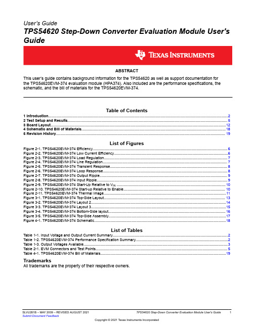
- 3、如文档侵犯您的权益,请联系客服反馈,我们会尽快为您处理(人工客服工作时间:9:00-18:30)。
6,4 mm x 9,7 mmTRANSIENT RESPONSEV I = 3.3 VV O = 1.25 V2.25 A to 6.75 A–OutputVoltage–5mV/divVOt – Time – µs/div–OutputCurrent–2A/divIOTPS54972SLVS437A—AUGUST2002–REVISED DECEMBER2002 9-A OUTPUT,3-V TO4-V INPUT TRACKING/TERMINATIONSYNCHRONOUS PWM SWITCHER WITH INTEGRATED FETS(SWIFT™)FEATURES DESCRIPTION•Tracks Externally Applied Reference Voltage As a member of the SWIFT™family of dc/dc regulators,the TPS54972low-input voltage high-output current •15-mΩMOSFET Switches for High Efficiency atsynchronous-buck PWM converter integrates all 9-A Continuous Output Source or Sink Currentrequired active components.Included on the substrate •6%to90%V I Output Tracking Rangewith the listed features are a true,high performance,•Wide PWM Frequency:Fixed350kHz or voltage error amplifier that enables maximum Adjustable280kHz to700kHz performance under transient conditions and flexibility in •Load Protected by Peak Current Limit and choosing the output filter L and C components;an Thermal Shutdown under-voltage-lockout circuit to prevent start-up until the •Integrated Solution Reduces Board Area and input voltage reaches3.0V;an internally set slow-start Total Cost circuit to limit in-rush currents;and a status output toindicate valid operating conditions. APPLICATIONS The TPS54972is available in a thermally enhanced28-pin TSSOP(PWP)PowerPAD™package,which •DDR Memory Termination Voltageeliminates bulky heatsinks.TI provides evaluation •Active Termination of GTL and SSTLmodules and the SWIFT designer software tool to aid in High-Speed Logic Familiesquickly achieving high-performance power supply •DAC Controlled High Current Output Stagedesigns to meet aggressive equipment development •Precision Point of Load Power Supply cycles.SIMPLIFIED SCHEMATICPlease be aware that an important notice concerning availability,standard warranty,and use in critical applications of Texas Instruments semiconductor products and disclaimers thereto appears at the end of this data sheet.PRODUCTION DATA information is current as of publication date.Products Copyright©2002,Texas Instruments Incorporated conformto specifications perthe terms ofTexas Instruments standard warranty.Productionprocessing does notnecessarily include testing of allparameters.TPS54972 SLVS437A—AUGUST2002–REVISED DECEMBER2002These devices have limited built-in ESD protection.The leads should be shorted together or the device placed in conductive foamduring storage or handling to prevent electrostatic damage to the MOS gates.ORDERING INFORMATIONT A REFIN VOLTAGE PACKAGE PART NUMBER -40°C to85°C0.2V to1.75V Plastic HTSSOP(PWP)(1)TPS54972PWP(1)The PWP package is also available taped and reeled.Add an R suffix to the device type(i.e.,TPS54972PWPR).See the applicationsection of the data sheet for PowerPAD drawing and layout information.ABSOLUTE MAXIMUM RATINGSover operating free-air temperature range unless otherwise noted(2)TPS54972ENA-0.3V to7VVIN-0.3V to4.5V Input voltage range,V I RT-0.3V to6VVSENSE,REFIN-0.3V to4VBOOT-0.3V to17VVBIAS,COMP,STATUS-0.3V to7V Output voltage range,V OPH-0.6V to6VPH Internally Limited Source current,I OCOMP,VBIAS6mAPH16ASink current,I S COMP6mAENA,STATUS10mA Voltage differential AGND to PGND±0.3V Operating virtual junction temperature range,T J-40to125°C Storage temperature,T stg-65to150°C Lead temperature1,6mm(1/16inch)from case for10seconds300°C(2)Stresses beyond those listed under"absolute maximum ratings"may cause permanent damage to the device.These are stress ratingsonly,and functional operation of the device at these or any other conditions beyond those indicated under"recommended operating conditions"is not implied.Exposure to absolute-maximum-rated conditions for extended periods may affect device reliability.RECOMMENDED OPERATING CONDITIONSMIN NOM MAX UNIT Input voltage,V I34V Operating junction temperature,T J-40125°C2TPS54972 SLVS437A—AUGUST2002–REVISED DECEMBER2002 DISSIPATION RATINGS(3)(4)THERMAL IMPEDANCE T A=25°C POWER T A=70°C POWER T A=85°C POWER PACKAGEJUNCTION-TO-AMBIENT RATING RATING RATING 28Pin PWP with solder14.4°C/W 6.94W(5) 3.81W 2.77W 28Pin PWP without solder27.9°C/W 3.58W 1.97W 1.43W ELECTRICAL CHARACTERISTICST J=–40°C to125°C,V I=3V to4V(unless otherwise noted)PARAMETER TEST CONDITIONS MIN TYP MAX UNIT SUPPLY VOLTAGE,VINVIN Input voltage range 3.0 4.0Vf s=350kHz,RT open,PH pin open1115.8I(Q)Quiescent current f s=500kHz,RT=100kΩ,PH pin open1623.5mAShutdown,SS/ENA=0V1 1.4UNDER VOLTAGE LOCK OUTStart threshold voltage,UVLO 2.95 3.0VStop threshold voltage,UVLO 2.7 2.8VHysteresis voltage,UVLO0.140.16VRising and falling edge deglitch,UVLO(6) 2.5µs BIAS VOLTAGEOutput voltage,VBIAS I(VBIAS)=0 2.70 2.80 2.90VOutput current,VBIAS(7)100µA REGULATIONLine regulation(6)(8)I L=4A,f s=350kHz,T J=85°C0.04%/V Load regulation(6)(8)I L=0A to8A,f s=350kHz,T J=85°C0.03%/A OSCILLATORInternally set free running frequency RT open280350420kHzRT=180kΩ(1%resistor to AGND)252280308 Externally set free running frequency range RT=100kΩ(1%resistor to AGND)460500540kHzRT=68kΩ(1%resistor to AGND)663700762 Ramp valley(6)0.75VRamp amplitude(peak-to-peak)(6)1VMinimum controllable on time(6)200nsMaximum duty cycle(6)90%ERROR AMPLIFIERError amplifier open loop voltage gain1kΩCOMP to AGND(6)90110dBError amplifier unity gain bandwidth Parallel10kΩ,160pF COMP to AGND(6)35MHzError amplifier common mode input voltagePowered by internal LDO(6)0VBIAS V rangeInput bias current,VSENSE VSENSE=V ref60250nA(3)For more information on the PWP package,refer to TI technical brief,literature number SLMA002.(4)Test board conditions:•3"x3",4layers,thickness:0.062"• 1.5oz.copper traces located on the top of the PCB• 1.5oz.copper ground plane on the bottom of the PCB•12thermal vias(see Recommended Land Pattern in applications section of this data sheet)(5)Maximum power dissipation may be limited by overcurrent protection.(6)Specified by design(7)Static resistive loads only(8)Specified by the circuit used in Figure83TPS54972 SLVS437A—AUGUST2002–REVISED DECEMBER2002ELECTRICAL CHARACTERISTICS(continued)T J=–40°C to125°C,V I=3V to4V(unless otherwise noted)PARAMETER TEST CONDITIONS MIN TYP MAX UNIT Output voltage slew rate(symmetric),COMP 1.0 1.4V/µs PWM COMPARATORPWM comparator propagation delay time,PWMcomparator input to PH pin(excluding10-mV overdrive(6)7085ns deadtime)SLOW-START/ENABLEEnable threshold voltage,ENA0.82 1.20 1.40V Enable hysteresis voltage,ENA(6)0.03V Falling edge deglitch,ENA(6) 2.5µs Internal slow-start time 2.6 3.35 4.1ms STATUSOutput saturation voltage,PWRGD I sink=2.5mA0.180.30V Leakage current,PWRGD V I=3.6V1µA CURRENT LIMITCurrent limit V I=3.3V1115A Current limit leading edge blanking time100ns Current limit total response time200ns THERMAL SHUTDOWNThermal shutdown trip point(9)135150165°C Thermal shutdown hysteresis(9)10°C OUTPUT POWER MOSFETSV I=3.0V(10)1530r DS(on)Power MOSFET switches mΩV I=3.6V(10)1428(9)Specified by design(10)Matched MOSFETs low-side rproduction tested,high-side r DS(on)production tested.DS(on)4TPS54972 SLVS437A—AUGUST2002–REVISED DECEMBER2002TPS54972Externally Composed Pin-Out28Pin HTSSOP PowerPADTERMINAL FUNCTIONSTERMINALDESCRIPTIONNAME NO.AGND1Analog ground.Return for compensation network/output divider,slow-start capacitor,VBIAS capacitor,RT resistor, and SYNC pin.Connect PowerPAD connection to AGND.BOOT5Bootstrap output.0.022-µF to0.1-µF low-ESR capacitor connected from BOOT to PH generates floating drive for the high-side FET driver.COMP3Error amplifier output.Connect frequency compensation network from COMP to VSENSEENA27Enable input.Logic high enables oscillator,PWM control,and MOSFET driver circuits.Logic low disables operation and places device in a low quiescent current state.PGND15-19Power ground.High current return for the low-side driver and power MOSFET.Connect PGND with large copper areas to the input and output supply returns,and negative terminals of the input and output capacitors.A single pointconnection to AGND is recommended.PH6-14Phase input/output.Junction of the internal high-side and low-side power MOSFETs,and output inductor.RT28Frequency setting resistor input.Connect a resistor from RT to AGND to set the switching frequency,f s.REFIN26External reference input.High impedance input to slow-start and error amplifier circuits.STATUS4Open drain output.Asserted low when VIN<UVLO,VBIAS and internal reference are not settled or the internal shutdown signal is active.Otherwise STATUS is high.VBIAS25Internal bias regulator output.Supplies regulated voltage to internal circuitry.Bypass VBIAS pin to AGND pin with a high quality,low-ESR0.1-µF to1.0-µF ceramic capacitor.VIN20-24Input supply for the power MOSFET switches and internal bias regulator.Bypass VIN pins to PGND pins close to device package with a high-quality,low-ESR10-µF ceramic capacitor.VSENSE2Error amplifier inverting input.Connect to output voltage compensation network/output divider.5TPS54972SLVS437A —AUGUST 2002–REVISED DECEMBER 2002RELATED DC/DC PRODUCTS•TPS54372•TPS54672•TPS548726–4002585125D r a i n S o u r c e O n -S t a t e R e s t s t a n c e – m ΩT J – Junction Temperature – °C510152025–4002585125T J – Junction Temperature – °C D r a i n S o u r c e O n -S t a t e R e s t s t a n c e – mΩ–4002585125T J – Junction Temperature – °Cf – I n t e r n a l l y S e t O s c i l l a t o r F re q u e n c y – k H zT J – Junction Temperature – °C f – E x t e r n a l l y S e t O s c i l l a t o r F r e q u e n c y – k H zI L – Load Current – ADe v i c e P o w e r L o s s e s – W2.752.903.053.203.353.503.65–402585125T J – Junction Temperature – °CI n t e r n a l S l o w -S t a r t T i m e – m s3.80f – Frequency – HzG a i n – d B P h a s e – D e g r e e s TPS54972SLVS437A —AUGUST 2002–REVISED DECEMBER 2002TYPICAL CHARACTERISTICSDRAIN-SOURCEDRAIN-SOURCEINTERNALLY SETON-STATE RESISTANCEON-STATE RESISTANCEOSCILLATOR FREQUENCYvsvsvsFigure 1Figure 2Figure 3EXTERNALLY SETDEVICE POWER LOSSESOSCILLATOR FREQUENCYINTERNAL SLOW-START TIMEvsvsvsLOAD CURRENTJUNCTION TEMPERATUREJUNCTION TEMPERATUREFigure 4Figure 5Figure 6ERROR AMPLIFIER Figure 77R+500kHzSwitching Frequency 100[k W](1)TPS54972SLVS437A—AUGUST2002–REVISED DECEMBER2002APPLICATION INFORMATIONFigure8shows the schematic diagram for a typical TPS54972application.The TPS54972(U1)can provide up to9A of output current at a nominal output voltage of one half of V(DDQ)(typically1.25V).For proper operation,the PowerPAD underneath the integrated circuit TPS54972is soldered directly to the printed-circuit board.COMPONENT SELECTIONThe values for the components used in this design example were selected for good transient response and small PCB area.Ceramic dielectric capacitors are utilized in the output filter circuit.A small size,small value output inductor is also pensation network components are chosen to maximize closed loop bandwidth and provide good transient response characteristics.Additional design information is available at .INPUT VOLTAGEThe input voltage is a nominal3.3VDC.The input filter(C4)is a10-µF ceramic capacitor(Taiyo Yuden).Capacitor C8, a10-µF ceramic capacitor(Taiyo Yuden)that provides high frequency decoupling of the TPS54972from the input supply,must be located as close as possible to the device.Ripple current is carried in both C4and C8,and the return path to PGND should avoid the current circulating in the output capacitors C7,C9,C11,and C12.FEEDBACK CIRCUITThe values for these components are selected to provide fast transient response ponents R1,R2,R3,C1, C2,and C3form the loop compensation network for the circuit.For this design,a type3topology is used.The transfer function of the feedback network is chosen to provide maximum closed loop gain available with open loop characteristics of the internal error amplifier.Closed loop cross-over frequency is typically between70kHz and80kHz for input from3V to4V.OPERATING FREQUENCYIn the application circuit,RT is grounded through a71.5kΩresistor to select the operating frequency of700kHz.To set a different frequency,place a68-kΩto180-kΩresistor between RT(pin28)and analog ground or leave RT floating to select the default of350kHz.The resistance can be approximated using the following equation:8FF TPS54972SLVS437A —AUGUST 2002–REVISED DECEMBER 2002Figure 8.Application CircuitOUTPUT FILTERThe output filter is composed of a 0.65-µH inductor and three 22-µF capacitors.The inductor is a low dc resistance (0.017Ω)type,Pulse PA02770.65-µH.The capacitors used are 22µF,6.3-V ceramic types with X5R dielectric.An additional 1-µF output capacitor (C12)is included to suppress high frequencies.GROUNDING AND POWERPAD LAYOUTThe TPS54972has two internal grounds (analog and power).Inside the TPS54972,the analog ground ties to all of the noise sensitive signals,while the power ground ties to the noisier power signals.The PowerPAD must be tied directly to AGND.Noise injected between the two grounds can degrade the performance of the TPS54972,particularly at higher output currents.However,ground noise on an analog ground plane can also cause problems with some of the control and bias signals.For these reasons,separate analog and power ground areas are recommended.The analog ground area should be tied to the power ground area directly at the IC to reduce noise between the two grounds.The only components that should tie directly to the power ground area are the input capacitor,the output capacitor,the input voltage decoupling capacitor,and the PGND pins of the TPS54972.The power ground areas as well as the PowerPAD mounting area should be tied to any internal ground planes using multiple vias.The layout of the TPS54972evaluation module is representative of a recommended layout for a 4-layer board with the two internal layers representing the system ground plane.Documentation for the TPS54972evaluation module can be found on the Texas Instruments web site under the TPS54972product folder.9TPS54972SLVS437A —AUGUST 2002–REVISED DECEMBER 2002LAYOUT CONSIDERATIONS FOR THERMAL PERFORMANCEFor operation at full rated load current,the analog ground plane must provide adequate heat dissipating area.A 3inch by 3inch plane of 1ounce copper is recommended,though not mandatory,depending on ambient temperature and airflow.Most applications have larger areas of internal ground plane available,and the PowerPAD should be connected to the largest area available.Additional areas on the top or bottom layers also help dissipate heat,and any area available should be used when 9A or greater operation is desired.Connection from the exposed area of the PowerPAD to the analog ground plane layer should be made using 0.013inch diameter vias to avoid solder wicking through the vias.Eight vias should be in the PowerPAD area with four additional vias located under the device package.The size of the vias under the package,but not in the exposed thermal pad area,can be increased to 0.018.Additional vias beyond the ten recommended that enhance thermal performance should be included in areas not under the device package.Figure 9.Recommended Land Pattern for 28-Pin PWP PowerPAD10I O – Output Current – AE f f i c i e n c y – %246810L o a d R e g u l a t i o nI O – Output Current – A33.54V I – Input Voltage – VL i n e R e g u l a t i o n t – Time – 1 µs/divO u t p u t R i p p l e V o l t a g e – 10 m V /d i vf s = 700 kHz,I O =9 A,V I = 3.3 V,V O = 1.25 VV I = 3.3 V V O = 1.25 V2.25 A to 6.75 A– O u t p u t V o l t a g e – 50 m V /d i vV O t – Time – µs/div– O u t p u t C u r r e n t –2 A /d i vI O – I n p u t V o l t a g e 1V /d i vV I t – Time – 2.5 µs/divV I = 3.3 V V O = 1.25 V– O u t p u t v o l t a g e – 500 m V /d i vV OA m b i e n t T e m p e r a t u r e – C°I O – Output Current – A– O u t p u t V o l t a g e 50m V /d i vV O t – Time – 2.5 µs/divV I = 3.3 V V O = 1.25 V– O u t p u t C u r r e n t 5A /d i vI O TPS54972SLVS437A —AUGUST 2002–REVISED DECEMBER 2002PERFORMANCE GRAPHST A =25°C (unless otherwise noted)LINE REGULATIONEFFICIENCYLOAD REGULATIONvsvsvsINPUT VOLTAGEOUTPUT CURRENTFigure 10Figure 11Figure 12OUTPUT RIPPLE VOLTAGETRANSIENT RESPONSESLOW-START TIMINGFigure 13Figure 14Figure 15AMBIENT TEMPERATUREvsOUTPUT CURRENT 1SOURCE-SINKTRANSIENT RESPONSE1.Safe operating area is applicable to the test board conditionslisted in the dissipation rating table section of this data sheet.Figure 16Figure 1711Switching Frequency+100k WR 500[kHz]TPS54972SLVS437A—AUGUST2002–REVISED DECEMBER2002DETAILED DESCRIPTIONUNDERVOLTAGE LOCKOUT(UVLO)The TPS54972incorporates an undervoltage lockout circuit to keep the device disabled when the input voltage(VIN)is insufficient.During power up,internal circuits are held inactive until VIN exceeds the nominal UVLO threshold voltage of2.95V.Once the UVLO start threshold is reached,device start-up begins.The device operates until VIN falls below the nominal UVLO stop threshold of2.80V.Hysteresis in the UVLO comparator,and a2.5-µs rising and falling edge deglitch circuit reduce the likelihood of shutting the device down due to noise on VIN.ENABLE(ENA)The enable pin,ENA,provides a digital control to enable or disable(shut down)the TPS54972.An input voltage of 1.4V or greater ensures the TPS54972is enabled.An input of0.9V or less ensures the device operation is disabled. These are not standard logic thresholds,even though they are compatible with TTL outputs.When ENA is low,the oscillator,slow-start,PWM control and MOSFET drivers are disabled and held in an initial state ready for device start-up.On an ENA transition from low to high,device start-up begins with the output starting from 0V.SLOW-STARTThe slow-start circuit provides start-up slope control control of the output voltage to limit in-rush currents.The nominal internal slow-start rate is0.25V/ms with the minimum rate being0.35V/ms.When the voltage on REFIN rises faster than the internal slope or is present when device operation is enabled,the output rises at the internal rate.If the reference voltage on REFIN rises more slowly,then the output rises at approximately the same rate as REFIN. VBIAS REGULATOR(VBIAS)The VBIAS regulator provides internal analog and digital blocks with a stable supply voltage over variations in junction temperature and input voltage.A high quality,low-ESR,ceramic bypass capacitor is required on the VBIAS pin.X7R or X5R grade dielectrics are recommended because their values are more stable over temperature.The bypass capacitor should be placed close to the VBIAS pin and returned to AGND.External loading on VBIAS is allowed,with the caution that internal circuits require a minimum VBIAS of2.70V,and external loads on VBIAS with ac or digital switching noise may degrade performance.The VBIAS pin may be useful as a reference voltage for external circuits.VOLTAGE REFERENCEThe REFIN pin provides an input for a user supplied tracking voltage.Typically this input is one half of V(DDQ).The input range for this external reference is0.2V to1.75V.Above this level,the internal bandgap reference overrides the externally supplied reference voltage.OSCILLATOR AND PWM RAMPThe oscillator frequency can be set to an internally fixed value of350kHz by leaving the RT pin unconnected(floating). If a different frequency of operation is required for the application,the oscillator frequency can be externally adjusted from280to700kHz by connecting a resistor to the RT pin to ground.The switching frequency is approximated by the following equation,where R is the resistance from RT to AGND:The following table summarizes the frequency selection configurations:SWITCHING FREQUENCY RT PIN350kHz,internally set FloatExternally set280kHz to700kHz R=68kΩto180kΩERROR AMPLIFIERThe high performance,wide bandwidth,voltage error amplifier sets the TPS54972apart from most dc/dc converters. The user has a wide range of output L and C filter components to suit the particular application needs.Type2or type3 compensation can be employed using external compensation components.12TPS54972 SLVS437A—AUGUST2002–REVISED DECEMBER2002 PWM CONTROLSignals from the error amplifier output,oscillator and current limit circuit are processed by the PWM control logic. Referring to the internal block diagram,the control logic includes the PWM comparator,OR gate,PWM latch,and portions of the adaptive dead-time and control logic block.During steady-state operation below the current limit threshold,the PWM comparator output and oscillator pulse train alternately reset and set the PWM latch.Once the PWM latch is set,the low-side FET remains on for a minimum duration set by the oscillator pulse width.During this period,the PWM ramp discharges rapidly to its valley voltage.When the ramp begins to charge back up,the low-side FET turns off and high-side FET turns on.As the PWM ramp voltage exceeds the error amplifier output voltage,the PWM comparator resets the latch,thus turning off the high-side FET and turning on the low-side FET.The low-side FET remains on until the next oscillator pulse discharges the PWM ramp.During transient conditions,the error amplifier output could be below the PWM ramp valley voltage or above the PWM peak voltage.If the error amplifier is high,the PWM latch is never reset and the high-side FET remains on until the oscillator pulse signals the control logic to turn the high-side FET off and the low-side FET on.The device operates at its maximum duty cycle until the output voltage rises to the regulation set-point,setting VSENSE to approximately the same voltage as VREF.If the error amplifier output is low,the PWM latch is continually reset,and the high-side FET does not turn on.The low-side FET remains on until the VSENSE voltage decreases to a range that allows the PWM comparator to change states.The TPS54972is capable of sinking current continuously until the output reaches the regulation set-point.If the current limit comparator trips for longer than100ns,the PWM latch resets before the PWM ramp exceeds the error amplifier output.The high-side FET turns off,and the low-side FET turns on to decrease the energy in the output inductor and consequently the output current.This process is repeated each cycle in which the current limit comparator is tripped.DEAD-TIME CONTROL AND MOSFET DRIVERSAdaptive dead-time control prevents shoot-through current from flowing in both N-channel power MOSFETs during the switching transitions by actively controlling the turnon times of the MOSFET drivers.The high-side driver does not turn on until the gate drive voltage to the low-side FET is below2V,while the low-side driver does not turn on until the voltage at the gate of the high-side MOSFET is below2V.The high-side and low-side drivers are designed with 300-mA source and sink capability to quickly drive the power MOSFETs gates.The low-side driver is supplied from VIN,while the high-side drive is supplied from the BOOT pin.A bootstrap circuit uses an external BOOT capacitor and an internal2.5-Ω.bootstrap switch connected between the VIN and BOOT pins.The integrated bootstrap switch improves drive efficiency and reduces external component count.OVERCURRENT PROTECTIONThe cycle by cycle current limiting is achieved by sensing the current flowing through the high-side MOSFET and comparing this signal to a preset overcurrent threshold.The high side MOSFET is turned off within200ns of reaching the current limit threshold.A100ns leading edge blanking circuit prevents false tripping of the current limit when the high-side switch is turning on.Current limit detection occurs only when current flows from VIN to PH when sourcing current to the output filter.Load protection during current sink operation is provided by thermal shutdown.THERMAL SHUTDOWNThe device uses the thermal shutdown to turn off the power MOSFETs and disable the controller if the junction temperature exceeds150°C.The device is released from shutdown automatically when the junction temperature decreases to10°C below the thermal shutdown trip point,and starts up under control of the slow-start circuit.Thermal shutdown provides protection when an overload condition is sustained for several milliseconds.With a persistent fault condition,the device cycles continuously;starting up by control of the soft-start circuit,heating up due to the fault condition,and then shutting down upon reaching the thermal limit trip point.This sequence repeats until the fault condition is removed.13TPS54972 SLVS437A—AUGUST2002–REVISED DECEMBER2002STATUSThe status pin is an open drain output that indicates when internal conditions are sufficient for proper operation. STATUS can be coupled back to a system controller or monitor circuit to indicate that the termination or tracking regulator is ready for start-up.STATUS is high impedance when the TPS54972is operating or ready to be enabled. STATUS is active low if any of the following occur:•VIN<UVLO threshold•VBIAS or internal reference have not settled.•Thermal shutdown is active.14TPS54972SLVS437A —AUGUST 2002–REVISED DECEMBER 2002MECHANICAL DATAPWR (R-PDSO-G**)PowerPAD™PLASTIC SMALL-OUTLINE(A)All linear dimensions are in millimeters.(B)This drawing is subject to change without notice.(C)Body dimensions do not include mold flash or protrusions.(D)The package thermal performance may be enhanced by bonding the thermal pad to an external thermal plane.This pad is electrically and thermally connected to the backside of the die and possibly selected leads.(E)Falls within JEDEC MO-15315IMPORTANT NOTICETexas Instruments Incorporated and its subsidiaries (TI) reserve the right to make corrections, modifications, enhancements, improvements, and other changes to its products and services at any time and to discontinue any product or service without notice. Customers should obtain the latest relevant information before placing orders and should verify that such information is current and complete. All products are sold subject to TI’s terms and conditions of sale supplied at the time of order acknowledgment.TI warrants performance of its hardware products to the specifications applicable at the time of sale in accordance with TI’s standard warranty. Testing and other quality control techniques are used to the extent TI deems necessary to support this warranty. Except where mandated by government requirements, testing of all parameters of each product is not necessarily performed.TI assumes no liability for applications assistance or customer product design. Customers are responsible for their products and applications using TI components. To minimize the risks associated with customer products and applications, customers should provide adequate design and operating safeguards.TI does not warrant or represent that any license, either express or implied, is granted under any TI patent right, copyright, mask work right, or other TI intellectual property right relating to any combination, machine, or process in which TI products or services are used. Information published by TI regarding third–party products or services does not constitute a license from TI to use such products or services or a warranty or endorsement thereof. Use of such information may require a license from a third party under the patents or other intellectual property of the third party, or a license from TI under the patents or other intellectual property of TI.Reproduction of information in TI data books or data sheets is permissible only if reproduction is without alteration and is accompanied by all associated warranties, conditions, limitations, and notices. Reproduction of this information with alteration is an unfair and deceptive business practice. TI is not responsible or liable for such altered documentation.Resale of TI products or services with statements different from or beyond the parameters stated by TI for that product or service voids all express and any implied warranties for the associated TI product or service and is an unfair and deceptive business practice. TI is not responsible or liable for any such statements.Mailing Address:Texas InstrumentsPost Office Box 655303Dallas, Texas 75265Copyright 2002, Texas Instruments Incorporated。