3M F2000复合体操作说明
M03.0022_Chinese_2022-07说明书

操作说明控制器B500/B510C540/C550P570/P580M03.0022 CHINESISCH原版使用说明书 ◼ Made ◼ in ◼ GermanyCopyright© Copyright byNabertherm GmbH Bahnhofstrasse 2028865 LilienthalFederal Republic of Germany Reg: M03.0022 CHINESISCH Rev: 2022-07内容可能会修改,保留技术更改权利1引言 (7)2质保和责任 (8)2.1一般说明 (8)2.2环境条件 (9)2.3废料处理 (9)2.4产品说明 (9)2.5规定用途 (10)2.6符号说明 (10)3安全说明 (13)4运行 (14)4.1接通控制器/窑炉 (14)4.2关闭控制器/窑炉 (14)5控制器的构造 (15)5.1控制器的各个模块的布局 (15)5.2操作页面区域 (16)5.2.1“菜单栏”区域 (16)5.2.2“小区段播放器”区域 (17)5.2.3“大区段播放器”区域 (18)5.2.4“状态栏”区域 (19)6控制器性能特性 (20)7简要使用说明 B500/B510/C540/C550/P570/P580 (22)7.1基本功能 (22)7.2输入新程序 (程序表) (24)8概览图 (29)8.1“窑炉”概览(无程序处于活动状态) (29)8.2“窑炉”概览(程序处于活动状态) (29)9待机模式 (31)10显示、输入或更改程序 (31)10.1“程序”概览 (32)10.2显示并启动程序 (33)10.3分配并管理程序类别 (34)10.4输入程序 (36)10.5利用NTEdit在电脑上准备程序 (44)10.6管理程序(删除/复制) (44)10.7什么是Holdback? (45)10.8修改正在运行的程序 (46)10.9完成区段跳跃 (47)11设定参数 (48)11.1“设置”概览 (48)11.2校准量程 (48)11.3调节参数 (52)11.4调节性能 (54)11.4.1磨平 (54)11.4.2加热延迟 (55)11.4.3手动区段控制 (56)11.4.4在程序启动时将实际值作为额定值接受 (57)11.4.5受控冷却(选项) (58)11.4.6起动连接/功率限制 (60)11.4.7自优化 (61)11.4.8程序运行中的炉料控制 (63)11.4.9用于各个区间的额定值补偿 (65)11.4.10Holdback (66)11.5用户管理 (67)11.6控制器锁闭和操作禁用 (71)11.7连续锁闭(操作禁用) (71)11.7.1运行中的程序控制器锁闭 (71)11.8配置额外功能 (72)11.9收起或重命名附加功能 (73)11.9.1在一个加热程序运行期间人工操作额外功能 (73)11.9.2在一个加热程序之后人工操作额外功能 (74)11.10警报功能 (75)11.10.1警报 (1 和 6) (75)11.10.2可听报警(可选) (78)11.10.3监测梯度 (78)11.10.4警报配置举例 (80)11.11设定电网中断时的反应 (81)11.12系统设置 (82)11.12.1设定日期和钟点时间 (82)11.12.2设置日期和钟点时间格式 (82)11.12.3设定语种 (83)11.12.4调节显示屏亮度 (84)11.12.5调整温度单位 (°C/°F) (84)11.12.6设定数据接口 (85)11.12.7设置Wi-Fi端口 (88)11.13导入和导出过程数据、程序和参数 (90)11.14登录模块 (92)11.15对空气循环器的控制 (93)12信息菜单 (93)13过程记录 (95)13.1使用NTLog将数据保存到U盘 (95)13.2保存过程数据并使用VCD软件管理程序(可选) (99)14连接到MyNabertherm App (100)14.1故障排除 (104)15与控制器的通信 (104)15.1通过 Modbus-TCP 和上一级系统进行沟通 (104)15.2网络服务器 (105)15.3通信模块的补装 (107)15.3.1供货范围 (107)15.3.2安装一个通信模块 (107)16可设置关闭温度的温度选择限制器(附加配置) (109)17无电势触点用于开启外部设备以及接收监控信号(可选) (109)18故障消息或警告 (110)18.1控制器的故障消息 (110)18.2控制器警告 (112)18.3开关设备的故障 (114)18.4控制器的检查列表 (115)19技术数据 (117)19.1铭牌 (119)20清洁 (119)21维护和备件 (119)21.1更换一个控制器 (120)21.2调节器模块的拆卸 (120)21.3调节器模块的安装 (121)22电气连接 (121)22.1调节器模块 (121)22.2对电缆的要求 (122)22.3一般性连接 (122)22.4至 3.6 kW 的窑炉–用于 B130, B150, B180, C280, P330 的备件,截止 2008 年 12 月止 (123)22.5至 3.6 kW 的窑炉–用于 B130, B150, B180, C280, P330 的备件,从 2009 年 1 月起 (124)22.6窑炉,单区式> 3.6 k,带半导体继电器或接触器 (125)22.7窑炉> 3.6 kW,带 2 个加热回路 (126)23纳博热售后服务 (127)24您的备忘录......................................................................................................... Fehler! Textmarke nicht definiert.1 引言尊敬的客户:非常感谢您对纳博热有限公司产品的信任和支持。
3M使用手册

3Scotch-Grip TMIndustrial Adhesive4799Features•Quick drying with fast strength buildup.•Provides low soak in on most porous substrates.•Dries to a flexible, water resistant bond.•Can be used to bond most EPDM rubber, sponge rubber, rubber sheeting, felt, canvas,linoleum and other lightweight materials to many metals, woods, concrete and many plastics.Handling/Application Information D irections for Use1.Surface Preparation: Surfaces to be bonded must be clean, dry and dust free. Wiping withsolvent such as Scotch-Grip TM Solvent No. 3 will aid in removing oil and dirt.*2.Application Temperature: For best results the temperature of the adhesive and thesurfaces being bonded must be at least 65°F (18°C).3.Application: Stir or agitate well before using.Porous Surface(s): Brush a uniform, generous coat of adhesive on the least poroussurface to be bonded. Assemble the materials immediately with sufficient pressure toensure contact.Non-Porous Surface(s): Apply a uniform coat of adhesive to each surface. Allowadhesive to dry until it is tacky, but does not transfer. Assemble materials withsufficient pressure to ensure contact.4.Cleanup: Excess adhesive may be removed with solvent such as Scotch-Grip TM SolventNo. 2.**Note:When using solvents, extinguish all sources of ignition in the area and follow the manufacturer’s precautions and directions for use when handling such materials.(Supersedes June, 1995)Typical Physical Properties Note:The following technical information and data should be considered representative or typical only and should not be used for specification purposes.Viscosity (approx.)7,500-18,000 cps.Brookfield Viscometer RVF #6 sp. @ 20 rpmSolids (by wt.)28-35%Base SBRColor BlackNet Weight (approx.) 6.6 - 7.0 lbs./gal.Flash Point (closed cup)-14°F (-26°C)Solvent Petroleum Distillate, n-hexane and toluene Note:Appropriate application equipment can enhance adhesive performance. The user is responsible for evaluating application equipment in light of the user’sparticular purpose and method of application.1.Pumping: Use a 5:1 ratio double acting, ball check pump with a 3 inch diameter air motor.All packings and glands in contact with the adhesive should be Teflon®coated.2.Hoses: Material hoses should be nylon lined with a working pressure of 500 psi or greater.3.Brushes: Brushes designed for use with oil based paint may be used.Application Equipment SuggestionsScotch-GripTMIndustrial Adhesive 4799180°PEEL STRENGTH – Canvas/SteelTimeTest Value@ 75°F (24°C)Temp.(lbs./in. width)1 day 75°F (24°C)15.53 days 75°F (24°C)225 days 75°F (24°C)257 days 75°F (24°C)25.52 wk.75°F (24°C)27.53 wk.75°F (24°C)28after 3 wk.-30°F (-34°C)14after 3 wk.150°F (66°C)8.5after 3 wk.180°F (82°C)5Typical Adhesive Performance CharacteristicsNote:The following technical information and data should be considered representativeor typical only and should not be used for specification purposes.Storage: Store product at 60-80°F (16-27°C) for maximum storage life. Higher temperatures reduce normal storage life. Lower temperatures cause increased viscosity of a temporary nature. Rotate stock on a “first in-first out” basis.Shelf Life: When stored at the recommended conditions and kept in the original, unopened container, this product has a shelf life of 1 year from date of shipment.Storage and Shelf Life3Adhesives Division3M Center, Building 220-7E-05St. Paul, MN 55144-10001-800-364-3577 or 612-737-6501T eflon is a registered trademark of E.I. DuPont de Nemours Co.Printed in U.S.A.©3M 199778-6900-2823-4For Additional Product Safety and Health Information, See Material Safety Data Sheet, or call:Recycled Paper 40% pre-consumer 10% post-consumerT o request additional product information or to arrange for sales assistance, call toll free 1-800-362-3550.Address correspondence to: 3M Adhesives Division, 3M Center, Building 220-7E-05, St. Paul, MN 55144-1000. Our fax number is 612-733-9175. In Canada, phone: 1-800-364-3577. In Puerto Rico,phone: 1-809-750-3000. In Mexico, phone: 5-728-2180.For Additional Information 3M MAKES NO WARRANTIES, EXPRESS OR IMPLIED, INCLUDING, BUT NOT LIMITED TO, ANY IMPLIED WARRANTY OF MERCHANT ABILITY OR FITNESS FOR A P ARTICULAR PURPOSE. User is responsible for determining whether the 3M product is fit for a particular purpose and suitable for user’s method of application. Please remember that many factors can affect the use and performance of a 3M Adhesives Division product in a particular application. The materials to be bonded with the product, the surface preparation of those materials, the product selected for use, the conditions in which the product is used, and the time and environmental conditions in which the product is expected to perform are among the many factors that can affect the use and performance of a 3M product. Given the variety of factors that can affect the use and performance of a 3M product, some of which are uniquely within the user’s knowledge and control, it is essential that the user evaluate the 3M product to determine whether it is fit for a particular purpose and suitable for the user’s method of application.Important NoticeIf the 3M product is proved to be defective, THE EXCLUSIVE REMEDY , A T 3M’S OPTION, SHALL BE TO REFUND THE PURCHASE PRICE OF OR TO REP AIR OR REPLACE THE DEFECTIVE 3M PRODUCT . 3M shall not otherwise be liable for loss or damages, whether direct, indirect, special,incidental, or consequential, regardless of the legal theory asserted, including negligence, warranty, or strict liability.Limitation of Remedies and LiabilityThis Adhesives Division product was manufactured under a 3M quality system registered to ISO 9002standards.Refer to Product Label and Material Safety Data Sheet for Health and Safety Information before using this product.Precautionary Information。
3M 定制热融合复合材料服务说明书

3M Custom Thermoplastic Compounding Services3M Advanced Materials Division3M offers you the convenience and fast response made possible by full-service, in-house custom thermoplastic compounding.With our Hebron, Kentucky facility, 3M has enhanced its capability to meet the plastic industry’s need for increasingly specialized and sophisticated polymer materials.Custom thermoplastic compounding gives our customers the ability to create formulations geared to providing specific properties or functions which are not inherent in the base polymer. Enhancements can range from making the base polymer easy to extrude, to adding properties specific to the requirements of an application; for example, reducing weight and/or improving dimensional stability.We are able to dedicate compounding lines to your applications, as well as create new processes for making a product. Products can be made using your formulation, or we can develop a formulation to meet your needs. 3M’s custom compounding facility includes a laboratory and all equipment to make and test any thermoplastic material, allowing us to assist you with your R&D programs.The Hebron custom compounding facility works closely with 3M’s Advanced Materials Division laboratory facilities in Oakdale, MN, which develop advanced ingredient and additive technologies for a variety of resin systems.Expanded capabilities, more capacity – for fast development and scale-up of your material needs.Facilities • 60,000 sq. ft. plant • T win screw compounding lines • S ingle screw compounding lines • C orrosion-protected compounding equipment • U nderwater, strand and hot face pelletizing • T esting laboratory •I SO 9001-2000 Certified With 3M custom compounding services, customers now have the ability to purchase thermoplastic compounds pre-formulated with any of 3M’s advanced polymer additive technologies. Improve processing and enhance properties with materials such as 3M ™ Fire Retardant Additives, lightweight, high-strength 3M ™ Glass Bubbles, and more – madeto order, all in one step.3M Advanced Materials Division3M Center St. Paul, MN 55144 USAP hone 1-800-367-8905 Web /advancedmaterials 3M is a trademark of 3M Company. Used under license by 3M subsidiaries and affiliates. Please recycle. Printed in USA © 3M 2017. All rights reserved. Issued: 3/17 12233HB 98-0050-0060-3Warranty, Limited Remedy, and Disclaimer: Many factors beyond 3M’s control and uniquely within user’s knowledge and control can affect the use and performance of a 3M product in a particular application. User is solely responsible for evaluating the 3M product and determining whether it is fit for a particular purpose and suitable for user’s method of application. User is solely responsible for evaluating third party intellectual property rights and for ensuring that user’s use of 3M product does not violate any third party intellectual property rights. Unless a different warranty is specifically stated in the applicable product literature or packaging insert, 3M warrants that each 3M product meets the applicable 3M product specification at the time 3M ships the product. 3M MAKES NO OTHER WARRANTIES OR CONDITIONS, EXPRESS OR IMPLIED, INCLUDING, BUT NOT LIMITED TO, ANY IMPLIED WARRANTY OR CONDITION OF MERCHANTABILITY OR FITNESS FOR A PARTICULAR PURPOSE OR ANY IMPLIED WARRANTY OF NON-INFRINGEMENT OR ANY IMPLIED WARRANTY OR CONDITION ARISING OUT OF A COURSE OF DEALING, CUSTOM OR USAGE OF TRADE. If the 3M product does not conform to this warranty, then the sole and exclusive remedy is, at 3M’s option, replacement of the 3M product or refund of the purchase price.Limitation of Liability: Except where prohibited by law, 3M will not be liable for any loss or damages arising from the 3M product, whether direct, indirect, special, incidental or consequential, regardless of the legal theory asserted, including warranty, contract, negligence or strict liability.Technical Information: Technical information, recommendations, and other statements contained in this document or provided by 3M personnel are based on tests or experience that 3M believes are reliable, but the accuracy or completeness of such information is not guaranteed. Such information is intended for persons with knowledge and technical skills sufficient to assess and apply their own informed judgment to the information. No licenseunder any 3M or third party intellectual property rights is granted or implied with this information.3M is one of the world’s leading fluoropolymer suppliers, with operations or representation in more than 50 countries. 3M products, including PTFE resins and compounds, fluoroplastics, fluoroelastomers, polymer processing additives, and high-strength, lightweight glass bubble products are used in a broad range of industries and markets, from transportation and chemical processing to architectural components and semiconductor manufacturing.Our in-house custom thermoplastic compounding services allow us to help customers meet their growth objectives.3M’s expertise in thermoplastic product development can help you decrease your development time and speed your product to commercial reality. We use a four-step process to provide the material you need:1. D efine the project – What are the target properties necessary for end product use? Will a thermoplastic material be suitable? What are the environments for this product? What the are cost factors that must be satisfied?2. M aterial selection – What properties give this product its best function? What processing is required? What materials satisfy these requirements? Will there be any manufacturing restraints? Are all of the ingredients available, or is additional information needed? Is regulatory approval or compliance needed? What is the probable cost?3. P rototyping – Does the selected material have the proper flow behavior for the product to be made on a commercial line? Are there special tooling requirements? What are the apparent needs for production? Are there special measurements needed for the product? What are the approximate costs to begin? Are all the materials and machinery readily available?4. P roduction – Which process makes the most sense for the product? How much prototyping is needed prior to production? Is the proper machinery available? What production rates are needed? What will the actual costs be for the product? What steps are needed for optimization? Will any post-forming actions be needed? When will production start?Custom Compounded Products• Micropellets• Antistatic Plastics• C onductive Polymers• P olyester Resins• A dditive Masterbatches• Lubricants• Custom Products• Colors/Color Blends• Purge Polymers• L ightweight Glass Bubble Masterbatches Typical Base Resins Processed • P VC • PP • P E • HDPE • T P E • TPV • TPU • ABS • SAN • PET • PC • PVA • PFA • ETFE • FEP • PVDF • THV。
SMC PF2A3 PF2W3 PF2D3 流量监测仪操作手册说明书
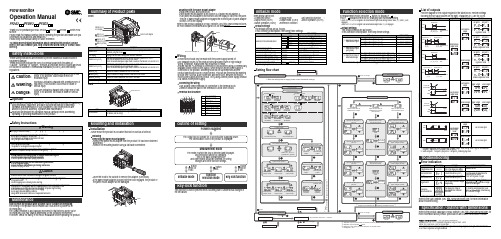
Flow MonitorOperation ManualPF2A3/PF2W3/PF2D3Installation•Never mount the product in a location that will be used as a foothold.Thank you for purchasing an SMC PF2A3/PF2W3/PF2D3Series Flow Monitor.Please read this manual carefully before operating the product and make sure you understand its capabilities and limitations.Please keep this manual handy for future reference.To obtain more detailed information about operating this product, please refer to the SMC website (URL ) or contact SMC directly.These safety instructions are intended to prevent hazardous situations and/or equipment damage.These instructions indicate the level of potential hazard with the labels of"Caution", "Warning" or "Danger". They are all important notes for safety and must be followed in addition to International standards (ISO/IEC) and other safety regulations.OperatorSafety InstructionsMaintenanceHow to reset the product after a power cut or forcible de-energizing The setting of the product will be retained as it was before a power cut or de-energizing.The output condition is also basically recovered to that before a power cut or de-energizing, but may change depending on the operating environment.Therefore, check the safety of the whole installation before operating the product.Mounting and InstallationInstallingRemoving the panel mount adapter•Remove the panel mount adapter from the product if it has been delivered assembled.•Remove the mounting bracket using a flat blade screwdriver.•Lever the hook to the outside to remove the adapter (See below).•If the panel mount adapter is pulled with the hook engaged, the product or the panel mount adapter will be damaged.FrontBackList of outputsFind the diagram of the output required in the table below. Perform settings following the Set value column on the right. Characters in ( ) are for OUT2.Key-lock functionThis function is used to prevent errors occurring due to unintentional changes of the set values.Default settingsThe default settings are as follows.If this condition is acceptable, then keep these settings.Default settingsThe default settings are as follows.If this condition is acceptable, then keep these settings.∗: When Non-Reverse output is selected as the switching operation, n becomes P.button, to display [F_].This [F_∗: When OUT1 or OUT2 is assigned to be instantaneous output mode during initialize mode, [F_1] and [F_2] are displayed.When OUT1 or OUT2 is assigned to be accumulated output mode, [F_3] is displayed.Items below can be set.•Connected sensor •Display mode •Unit selection function ∗•Output mode (OUT1)•Output mode (OUT2) •Switch operation (OUT1)•Switch operation (OUT2)•Reference condition TroubleshootingMounting with the panel mount adapter •Install the product as shown below.•Insert panel mount adapter B into section A of panel mount adapter A.Push panel mount adapter B from behind until the display is fixed onto the panel.The pin of panel mount adapter B engages the notched part of panel adapter section A to fix the display.Wiring•Connections should only be made with the power supply turned off.•Use separate routes for the product wiring and any power or high voltage wiring. Otherwise, malfunction may result due to noise.•Ensure that the FG terminal is connected to ground when using a commercially available switch-mode power supply. When a switch-mode power supply is connected to the product, switching noise will be superimposed and theproduct specification can no longer be met. This can be prevented by inserting a noise filter, such as a line noise filter and ferrite core, between the switch-mode power supply and the product, or by using a series power supply instead of a switch-mode power supply.Connecting the wiring•Use suitable crimp terminals for connection to the terminal block.•Attention should be paid to the terminals to avoid short circuits.Terminal block numberPower is suppliedOutline of settingMeasurement modeThe mode in which the flow is detected and displayed,and the switch function is operating.This is the basic operating mode;and other modes should be selected for settingchanges and other function settings.Function selection modeSpecification / Outline with DimensionsRefer to the product catalogue or SMC website (URL ) for more information about product specifications and outline dimensions in detail.Note: Specifications are subject to change without prior notice and any obligation on the part of the manufacturer.© 2011 SMC Corporation All Rights ReservedAkihabara UDX 15F , 4-14-1, Sotokanda, Chiyoda-ku, Tokyo 101-0021, JAP AN Phone: +81 3-5207-8249 Fax: +81 3-5298-5362URL Refer to the SMC website (URL ) for more information about troubleshooting.∗1: In window comparator mode, the hysteresis is fixed at 3 digits. When setting, allow 7 digits or more betweenSet point 1 and Set point 2 (Set point 3 and Set point 4).∗2: When Set point 1 = Set point 2 (Set point 3 = Set point 4), chattering may occur.Refer to the product catalogue or SMC website (URL )for more detailed information about panel cut-out dimensions.。
3m测试片操作手册
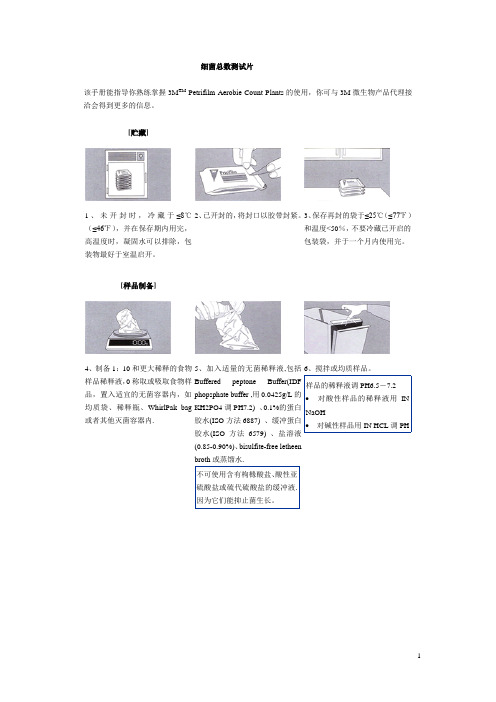
细菌总数测试片该手册能指导你熟练掌握3M TM Petrifilm Aerobie Count Plants的使用,你可与3M微生物产品代理接洽会得到更多的信息。
[贮藏]1、未开封时,冷藏于≤8℃(≤46℉),并在保存期内用完,高温度时,凝固水可以排除,包装物最好于室温启开。
2、已开封的,将封口以胶带封紧。
3、保存再封的袋于≤25℃(≤77℉)和温度<50%,不要冷藏已开启的包装袋,并于一个月内使用完。
[样品制备]4、制备1:10和更大稀释的食物样品稀释液,0称取或吸取食物样品,置入适宜的无菌容器内,如均质袋、稀释瓶、WhirlPak bag 或者其他灭菌容器内.5、加入适量的无菌稀释液,包括Buffered peptonephopsphate buffer ,用0.0425g/L的KH2PO4调PH7.2) 、0.1%的蛋白胶水(ISO方法6887) 、缓冲蛋白胶水(ISO方法6579) 、盐溶液(0.85-0.90%)、bisulfite-free letheenbroth或蒸馏水.6、搅拌或均质样品。
[接种]7、将测试片置于平坦表面处,揭开上层膜。
8、使用吸管将1mL样液垂直滴加在测试片的中央处。
9、允许使用上层膜直接落下,切勿向下滚动上层膜。
10、使用压板隆起面底朝下,放置在上层膜中央处。
11、轻轻的压下,使样液均匀覆盖于圆形的培养面积上,切勿扭转压板。
12、拿起压板,静置至少1分钟以使培养基凝固。
[培养][解释]13、测试片的透明面朝上,可堆叠至20片,对有一定湿度养箱能保持最少份损失是需要的。
14、可目视及用标准菌落计数器或其它的照明放大镜计数,并可参考判读卡计算菌落数。
15、可以分离菌落作进一步鉴定,即掀起上层膜,由培养胶上判读卡Aerobic bacteria count=152测试片中含有一种红色指示染剂可使菌落着色,计算所有红色菌落(不论其大小和颜色深浅均计算之).Count=0在petrifilm AC测试片上,很容易解释,图2测试片上没有任何菌落生长.Count=16图3示有不多的菌落.Count=143Petrifilm AC测试片菌落数适宜计数范围是25-250,见图4Count=560测试片面积约为20cm2,当菌落数超过250个,如图5所示,为了估计菌落数,可选择其中一个或数个有代表性菌落的小方格(1cm2),计算平均菌落数,再乘以20可得到整个测试片上的菌落数.Count=tntc(estimated count=103)图6所示petrifilm AC测试片上菌落太多而无法计数(tntc)count=tntc(Estimated count=105)有很多高数量菌落,使整个生长区变粉色,如图7所示,你仅可在生长区边缘现观察到单个菌落,应计录为菌落太多无法计数(TNTC)count=tntc(Estimated count=103)有时菌落分布出现不均衡,如图8所示,这也记录为TNTC.Count=tntc(Estimated count=107)在图9中petrifilm AC测试片上的菌落,最先粗略一看是可计数的,然而,你密切注意到生长区边缘,能看到高密度的菌落,应记录为TNTC Estimated count=160很少数菌种会液化petrifilm AC测试片上的培养基,如图10所示.若有这种现象发生,可选择没有液化区的几个有代表性菌落的小方格(1cm2),计算平均菌落数.不要计数液化区内的红点.Count=83因为在petrifilm AC测试片上菌落是红色的,你会和不透明的不规则形状的事物颗粒区分开,见圆圈1和2.霉菌和酵母菌检验测试片Petrifilm and Mold count Mold TM测试片为预先制备好的培养基系统,它含有一种冷水可溶性的凝胶剂,营养基和一种指示染剂,可提供对比,利于菌落计数。
品牌 F-03-002 型号 Rev AA 产品 操作和维护说明书
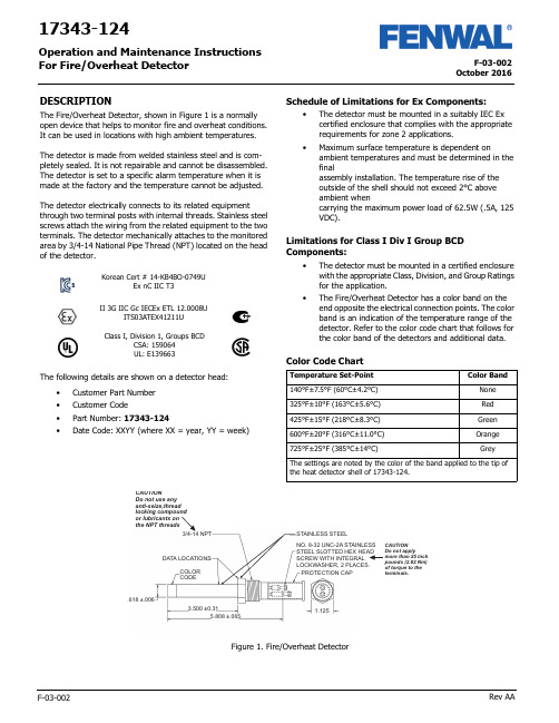
F-03-002October 2016F-03-002Rev AA17343-124Operation and Maintenance Instructions For Fire/Overheat DetectorDESCRIPTIONThe Fire/Overheat Detector, shown in Figure 1 is a normally open device that helps to monitor fire and overheat conditions. It can be used in locations with high ambient temperatures.The detector is made from welded stainless steel and is com-pletely sealed. It is not repairable and cannot be disassembled. The detector is set to a specific alarm temperature when it is made at the factory and the temperature cannot be adjusted.The detector electrically connects to its related equipmentthrough two terminal posts with internal threads. Stainless steel screws attach the wiring from the related equipment to the two terminals. The detector mechanically attaches to the monitored area by 3/4-14 National Pipe Thread (NPT) located on the head of the detector.The following details are shown on a detector head:•Customer Part Number •Customer Code•Part Number: 17343-124•Date Code: XXYY (where XX = year, YY = week)Schedule of Limitations for Ex Components:•The detector must be mounted in a suitably IEC Ex certified enclosure that complies with the appropriate requirements for zone 2 applications.•Maximum surface temperature is dependent onambient temperatures and must be determined in the finalassembly installation. The temperature rise of the outside of the shell should not exceed 2°C above ambient whencarrying the maximum power load of 62.5W (.5A, 125 VDC).Limitations for Class I Div I Group BCD Components:•The detector must be mounted in a certified enclosure with the appropriate Class, Division, and Group Ratings for the application.•The Fire/Overheat Detector has a color band on the end opposite the electrical connection points. The color band is an indication of the temperature range of the detector. Refer to the color code chart that follows for the color band of the detectors and additional data.Color Code ChartII 3G IIC Gc IECEx ETL 12.0008UITS03ATEX41211UClass I, Division 1, Groups BCDCSA: 159064UL: E139663Korean Cert # 14-KB4BO-0749UEx nC IIC T3Temperature Set-Point Color Band140°F±7.5°F (60°C±4.2°C)None 325°F±10°F (163°C±5.6°C)Red 425°F±15°F (218°C±8.3°C)Green 600°F±20°F (316°C±11.0°C)Orange 725°F±25°F (385°C±14°C)GreyThe settings are noted by the color of the band applied to the tip ofthe heat detector shell of 17343-124.NO. 8-32 UNC-2A STAINLESS STEEL SLOTTED HEX HEAD SCREW WITH INTEGRAL LOCKWASHER, 2 PLACES.3/4-14 NPTSTAINLESS STEELDATA LOCATIONSCOLOR CODEPROTECTION CAP.618 ±.0063.500 ±0.315.808 ±.0651.125the NPT threadsFigure 1. Fire/Overheat DetectorOctober 2016F-03-002 Rev AA2Specified data for the Fire/Overheat Detector is given in the table below .INSTALLATIONThis section gives the procedure to install the fire overheat detector .The fire/overheat detector must be attached to an IP 54 suitable/rated junction box with the applicable EquipmentGroup II and Category 3 for the installation. The box must have a 3/4 NPT opening to install the detector .The installer of the detector must supply a means to prevent non-permitted decrease of clearance per IEC60079-15, para-graph 6.7.Replacement parts must be the same part number as the part being replaced.Fastening of the fire detector is through the 3/4 NPT thread. Do not use any anti-seize thread locking compound or lubricant on the NPT threads. The installer must ensure that a proper ground connection is made to the IP 54 box-grounding termi-nal.Procedure1.Turn the detector clockwise into the related equipment’s 3/4 NPT opening a minimum of 5 full turns. Torque the detector to 20 lbf ft (27 Nm).2.Connect the related equipment’s system wiring to the detectors terminals with the No. 8-32 UNC-2A SS slotted hex head screws with integral washer . Make sure the wire connections do not touch each other . Torque the screws to a value between 20 and 25 lbf in. (2.26 and 2.82 Nm).3.Make sure that no objects touch the detector or can touch or damage it during usual system operation.4.Keep the detector free of contamination and unwanted materials. Refer to the Cleaning section.OPERATIONThe Fire/Overheat Detector’s outer shell is made of stainless steel that expands with an increase in temperature. It closely follows changes in the air temperature that surround it. Two inner struts, made of an alloy that expands at a lower rate than the outer shell, are sealed inside the outer shell. An overheat condition causes the shell to expand faster than the innerstruts. This makes the struts move together and make electrical connection through the contacts that are attached to the struts . The electrical connection of the contacts completes the circuit through the terminal posts on the end of the detector . Figure 2 shows a simplified diagram of the Fire/Overheat Detector oper-ation. When the shell and inner struts cool, the contacts open again.There are three conditions that can have an effect on the oper-ation of the detector , especially when a functional test of the detector is done. These conditions are:1.Temperature Overshoot: This condition can occur when the temperature of a detector increases far above its set-point range when heat is supplied too rapidly. This can cause the contacts to close before the specified tempera-ture range.2.Anticipation Effect: This condition causes the alarm circuit to close well before the alarm set-point. This condition is the result of the supply of high heat too rapidly.3.Temperature Undershoot: This condition occurs when the temperature of a detector decreases suddenly below its set-point range when made to cool too rapidly. The detec-tor should be air cool only.If possible, these conditions must be prevented, specially when tests of the detector are done.Figure 2. Detector Simplified DiagramSpecified Item or Function DataTemperature Range for Operation -50°F to +825°F (-45.5°C to +440.5°C)Electrical ContactRating 0.5 Ampere at 125VDCElectrical InterfaceConnection 2 each terminal posts with No. 8-32 UNC-2A Stainless Steel Slotted Hex HeadScrews with Integral LockwasherElectrical ConnectionTorque 25 lbf in. (2.8 Nm) maximum Electrical Connection Protection CapP/N RCL-10 (Vendor: Protective Closures Co., CAGE Code 99017)Dimensions See Figure 1ApprovalATEX approved for Zone 2, Category 3.Type of protection “nC”.Do not supply more than 25 lbf in. torque to the detector’s terminal screws or you can dam-age the detector . If the detector is damaged, you must discard it.Do not paint the detector or let paint from another source get on the detector or it will not operate correctly.READY OR STANDBY CONDITIONALARM OR OVERHEAT CONDITIONCONTACTS CLOSEDSHELL - HIGH EXPANSIONSTRUTS - LOW EXPANSION3October 2016F-03-002 Rev AA TestingThis section gives the equipment and procedures necessary to do tests of the detector and find if there is a malfunction.You must do a no-continuity test and an insulation resistance test to make sure the detector is serviceable.You must do a calibration verification test (or functional test) to make sure that the detector gives an alarm at the correct tem-perature.Testing EquipmentThe test equipment necessary to do the tests on the detector is given in the table below. You can use equivalent alternative items for those given in the table.Pretest InspectionBefore you test the detector , make sure that the detector’s visual inspection is acceptable. Refer to the Inspection section of this manual.No-Continuity TestDo the no-continuity test per the following procedure. Do the test at room temperature. If the test is unsatisfactory, replace the detector. Detector is not a repairable unit.Procedure1.Connect one lead of a digital multimeter (DMM) to one of the two terminals posts of the detector and the other lead of the DMM to the other terminal post. See the no-continuity test setup in Figure 3.2.With the DMM set to measure ohms (Ω) on the highest scale, read the resistance.3.The resistance value must read an open condition or infinite (∞).4.Disconnect the DMM from the detector .Figure 3. No-Continuity Test SetupInsulation Resistance TestDo the insulation resistance test per the following procedure. Do the test at room temperature. If the test is unsatisfactory, replace the detector . Detector is not a repairable unit.Procedure1.Connect one lead of a megohmmeter to the two terminal posts of the detector jumpered together. Connect the other lead of the megohmmeter to the detector shell. See the insulation resistance test setup in Figure 4.2.Set the megohmmeter to supply 500 VDC and measure the insulation resistance of the detector.3.The resistance must be 20 megohms (M Ω) or higher.4.Remove the power from the megohmmeter and disconnect the leads and jumper from the detector .Figure 4. Insulation Resistance Test SetupEquipment Item Range/Accuracy Manufacturer orSource Digital Multimeter , Fluke Model 77100VDC to 1000 VDC, 0.1Ω to 20M Ω,1% AccuracyFluke (CAGE 89536)Dry-Well Calibrator , Model 9141-A (used to verify calibra-tion set-point value)50 to 400°C ±0.5°CHart Scientific (CAGE 64841)Custom Insert, Model 3141-7 (for 9141-A, with one opening 0.629± 0.002in dia.)Not ApplicableHart Scientific (CAGE 64841)Power Source (to supply power to Dry-Well Calibrator 115 VAC, 50-60 Hz, 10 Amps or 230 VAC,5 Amps Get Locally Megohmmeter , Model 1867500 VDC, 20 M Ω andhigherQuad Tech (CAGE 0PK96)Prevent possible dangerous shock. Do not sup-ply power to the megohmmeter until it is con-nected to the detector .DETECTORDIGITALMULTIMETERDETECTORMEGOHMMETERJUMPEROctober 2016F-03-002 Rev AA4Calibration Verification Test1.The detector no-continuity test and insulationresistance test must be satisfactory before you do the calibration verification test.2.Make a test setup with the Model 9141 Dry-Well Calibrator. Make sure that you follow the safetyinstructions given in Section 3 of the Model 9141 Dry-Well Calibrator User Manual.3.Install the detector in the dry-well calibrator insert.4.Connect the dry-well calibrator test leads to the terminal posts on the detector.5.Connect the dry-well calibrator power cable to an applicable 115 or 230 VAC, 50-60 Hz power source.6.Follow the procedures in Section 7 of the Model 9141 Dry-Well Calibrator User Manual to make sure that the detector’s set-point is in limits.7.Record the temperature for each of three consecutive detector contact closures.8.Get an average of the three recorded values (add the three recorded values and divide by three). This is the detector set-point valve. The value must be the temperature shown on the detector ±25°F (±14°C).9.Remove the power from the dry-well calibrator and let the heater block and detector cool before you remove the detector under test.10.If the calibration verification test is unsatisfactory,replace the detector .DisassemblyThe fire/overheat detectors are hermetically sealed units. The detector cannot be disassembled.MAINTENANCECleaningThis section gives the procedure and materials necessary to clean the detector .MaterialsThe materials necessary to clean the detector are given in the table below. You can use equivalent alternatives for the items given in the table.Procedure1.Use a clean lint-free cloth wet with LPS Presolve solvent to clean the detector.2.Use nitrogen dry air at a maximum pressure of 30 psig (205 Kpa) to dry the detector .InspectionMake sure the detector is clean before you do the inspection. Refer to the Cleaning section.1.Examine the electrical connection terminals. Look for cracks or damage. If the connection terminals are damaged or cracked, discard the detector.2.Examine the electrical connection terminal screws. Look for damage to the screw threads and head. If damaged, replace the screws. Make sure the screws turn freely in the connection terminals. If the screws cannot be turned completely into the terminals, discard the detector.3.Examine the shell or tube of the detector. If there is a dent, scratch, or abrasion to the outer area, discard thedetector.Do not supply more than 25 lbf in. (2.82 Nm) torque to the screws in the detector terminals or you can damage the detector and it mustbe discarded.Be careful not to get burned from the hot heater block in the dry-well calibrator or the hot detector . The temperature can exceed 800°F or more.Be careful not to get burned by the hot heater block in the dry-well calibrator or the hot detector . The temperature can exceed 800°F or more.Materials Specification or Part No.Source Cloth, Clean Lint-free Solvent, LPS Presolve None 01428Get Locally LPS Laboratories (CAGE Code 66724)Nitrogen or Clean,Dry AirA-A-59503-1B1Get LocallyClean with solvents in an area that has good airflow. Do not clean near heat or open flame.While cleaning the detector , do not use abra-sive material or excessive force. This action will adversely affect the set point of the heat detector , compromising the accuracy of the detector .Be careful when you use compressed air or gas. Always point the flow away from person-nel. Compressed air or gas and the material moved by the air or gas pressure is dangerous and can cause injuries. Wear applicable eye protection.Fenwal Controls, Kidde-Fenwal Inc.400 Main Street Ashland, MA 01721Tel: 800-FENWAL-1Fax: 508-881-7619This literature is provided for informational purposes only. KIDDE-FENWAL, INC. assumes no responsibility for the product’s suitability for a particular application. The product must be properly applied to work correctly. If you need more information on this product, or have a particular problem or question, contact KIDDE-FENWAL, INC.F-03-002 Rev AA ©2016 Kidde-Fenwal, Inc.Storage and Movement1.Install a protection cap, P/N FS06-250099-071, over the electrical connection end of the detector.2.Make sure the detector has sufficient protection to prevent damage to the threads and outer shell.3.Put the detector in a container that is approved for storage.4.Keep the detector in a cool, dry area that has no contamination.5.If you must move the detector to another location, make sure it has sufficient protection to prevent damage.Fits and ClearancesTorque Values1.When you make electrical connection to the terminal posts, torque the screws to a value between 20 and 25 lbf. in (between2.26 and 2.28 Nm).2.When you install the detector, torque it to a value of 20 lbf. ft (27 Nm).Special Tools, Fixtures, Equipment and ConsumablesThe table below outlines the special tools, fixtures, equipment and consumable items needed to maintain the detector .Also provided are the vendors and the Commercial and Government Entity [CAGE] code.Do not torque the terminal post screws to a value more than 25 lbf in. or you can damage the detector . If the detector is damaged, you must discard it.DescriptionPart NumberVendorsRecommended SourceMultimeter Model 77Fluke Corporation 6920 Seaway BoulevardP .O. Box 9090Everett, WA 98206Fluke (CAGE 89536)Megohmmeter , 500 VDC, 20 M and higherModel 2867Quad Tech Inc.5 Clock Tower Place 210 East Maynard, MA 01754-2530Quad Tech (CAGE 0PK96)Dry-Well Calibrator Model 9141-A Hart Scientific799 E. Utah Valley Drive American Fork, Utah 84003-9775Hart Scientific (CAGE 64841)Customer Insert(used with Dry-Well Calibrator)Model 3141-7Cleaner/Degreaser , LPS Pre-Solve01428LPS Laboratories, Inc 4647 Hugh Howell Rd Tucker , GA 30085-5052LPS Laboratories (CAGE 66724)Protection Cap RCL-10Protective Closures Co., Inc.DBA Caplugs LLC Div. Caplugs Division2150 Elmwood Avenue Buffalo, NY 14207-1984Protective Closures Co.(CAGE 99017)Torque Screwdriver , 20 to 25 lbf in.None Specified Commercially Available Commercially Available Torque Wrench, 20 lbf ft.None SpecifiedCommercial AvailableCommercially AvailablePower Source, 115 VAC, 50-60 Hz, 10 Amps or230 VAC, 5 Amps(Necessary for Dry-Well Calibrator)None Get Locally Get Locally Cloth, Lint free None Get Locally Get Locally Nitrogen or Clean, Dry AirA-A-59503-1B1Get LocallyGet LocallyNote: All vendors are located in the United States.。
3M Dual Lock Reclosable Fasteners 说明书

Designing with 3M Dual Lock Reclosable FastenersSubstrate attachment & surface preparation3M™ Dual Lock™ Reclosable Fastener is attached to substrates through various means; the most prevalent is with pressure sensitive adhesive tapes pre-applied to the 3M Dual Lock Reclosable Fastener backing. The pressure sensitive adhesive tape requires a clean dry surface and firm even pressure (15psi) to ensure good contact with the surface of the substrate to which it is being applied.Most 3M Dual Lock Reclosable Fastener products will adhere best to high surface energy substrates, such as metals (like stainless steel, aluminum) or medium surface energy substrates (like ABS, polycarbonate, and acrylic). For low surfaceenergy substrates (like powder coated paint and other plastics), consider advance treatment of the surface with 3M™ T ape Primer 94 or 3M™ VHB™ T ape Universal Primer UV which will increase adhesion to many low surface energy substrates. Please refer to the 3M Dual Lock Reclosable Fasteners with Acrylic Foam T ape Application Guide for more information.Technical BulletinTemperature and environmental exposure3M™ Dual Lock™ Reclosable Fastener is designed to be applied between 68-80°F (20-27°C). For long term use in high temperatures or outdoor conditions please consider the following guidelines for temperature resistance:• SJ3560/61/62 220F (104°C• SJ3550/51/52 200F (93°C)• Other 3M Adhesive-backed products and non-adhesive backed products are available, including:• Piece parts: rigid backed 3M Dual Lock Reclosable Fastener pieces designed to be mechanically fastened to substrates • Low profile 3M Dual Lock Reclosable Fastener: minimal engaged thickness and reduced weight limit • Hook & loop: for applicationsFor more information on piece parts and other 3M Reclosable Fasteners, please contact your 3M Representative or 3MTechnical Service.Engagement and disengagement strengthIn one square inch there are approximately 170, 250 or 400 stems. • To achieve the desired attachment strength, start the evaluation with 250 to 250.• To increase the attachment strength, evaluate 250 to 400. • To decrease the attachment strength, evaluate 170 to 250.Note: If 250:250 is the correct strength but difficult to engage, we recommend evaluating 170:400.Note: We advise against 170:170 because the attachment will be very weak. We advise against 400:400 because you may not be able to engage the two sides completely or disengage them without damage.• SJ3870/71/72 158F (70°C)• SJ3540/41/42 120F (49°C)Design considerationsThe performance of 3M™ Dual Lock™ Reclosable Fastener depends on the design of the final assembly. The suggested starting point for evaluation is starting with four square inches (4 in2) of fastener area per pound of static tensile or shear load to be supported, increasing or decreasing the amount of fastener may be needed depending on the substrates and application, this should be tested in the specific application.Suggestions•Use 4 square inches of 3M™ Dual Lock™ Reclosable Fasteners per pound of dead load •Apply to a clean dry surface•Apply firm even pressure of at least 15 pounds per square inch•Apply the 3M Dual Lock Reclosable Fastener between 68-80°F (20-27°C)This technical bulletin is not a substitute for performance testing and should be used to identify the appropriate 3M Dual Lock Reclosable Fastener to begin your evaluation.Industrial Adhesives and Tapes Division 3M Center, Building 225-3S-06St. Paul, MN 55144 USA Phone 1-800-362-3550Web /DualLock© 3M 2019. All rights reserved.3M Dual Lock Reclosable Fastener, 3M and 3M ScienceApplied to Life are trademarks of 3M Company.Direct tensile3M™ Dual Lock™ Reclosable Fasteners are strongest in directtensile. Example applications include: vehicle headliners and ceiling tiles.Shear3M™ Dual Lock™ Reclosable Fastener is strong in shear. Example applications include: panel attachment, signageand graphics.Cleavage3M™ Dual Lock™ Reclosable Fastener is not intended to be used under peel or cleavage stresses in final application. Peel or cleavage is the weakest angle and is used to disengage or “remove” the 3M™ Dual L ock™ Reclosable Fastener component. If the 3M™ Dual Lock™ Reclosable Fastener is under constant stress at slight angles, the product may not meet technical performance specifications for adhesion or the forces can cause disengagement or creep to occur slowly over time. This includes examples where the product is not upright or hanging at a slight angle toward the ground.Warranty, Limited Remedy, and Disclaimer: Many factors beyond 3M’s control and uniquely within user’s knowledge and control can affect the use and performance of a 3M product in a particular application. User is solely responsible for evaluating the 3M product and determining whether it is fit for a particular purpose and suitable for user’s method of application. Unless an additional warranty is specifically stated on the applicable 3M product packaging or product literature, 3M warrants that each 3M product meets the applicable 3M product specification at the time 3M ships the product. 3M MAKES NO OTHER WARRANTIES OR CONDITIONS, EXPRESS OR IMPLIED, INCLUDING, BUT NOT LIMITED TO, ANY IMPLIED WARRANTY OR CONDITION OF MERCHANTABILITY OR FITNESS FOR A PARTICULAR PURPOSE OR ANY IMPLIED WARRANTY OR CONDITION ARISING OUT OF A COURSE OF DEALING, CUSTOM OR USAGE OF TRADE. If the 3M product does not conform to this warranty, then the sole and exclusive remedy is, at 3M’s option, replacement of the 3M product or refund of the purchase price. Limitation of Liability: Except where prohibited by law, 3M will not be liable for any loss or damage arising from the 3M product, whether direct, indirect, special, incidental or consequential, regardless of the legal theory asserted, including warranty, contract, negligence or strict liability.。
3M F2000复合体操作说明

3M F2000复合体操作说明来源:网站管理员点击次数:64次发布时间:2010-12-6 14:59:25 3MF2000复合体修复材料3MF2000复合体修复材料是一种单组份、光固化、释氟的糊状材料,它具有优良的操作性能和物理特性,有9种维他牙色色号供选用(包括A2,A3,A3.5,A4,B2,B3,C2,C4,D3)和4种特别色(包括儿童色,CG颈部灰色,CY颈部黄色,及蓝色),既有单个使用的胶囊装也有多计量的注射管装。
适应证:3MF2000复合体修复材料适用于:1,III类洞;2,V类洞及牙颈部蚀损;3,根部龋;4,II类分层或三明治式充填技术;5,乳牙的I 类洞及II类洞;6,折断牙的临时修复;7,牙冠折断近半时制作桩核以支持人造冠;对牙科人员及患者的预警:3MF2000复合体修复材料含有甲基丙烯酸盐,已知有小比例的人群会对丙烯酸树脂发生过敏。
为减少过敏反应的危险,要把与这种材料的接触减至最小。
特别要避免对未固化树脂的接触。
我们推荐使用防护手套及不接触技术。
如果复合体修复材料接触了皮肤可立即用肥皂和水清洗。
丙烯酸可以穿透普通用旧的手套,如果复合体修复材料接触了手套,可将手套脱下丢掉,立即用肥皂和水洗手,然后换手套。
未固化的复合体修复材料对口腔软组织会有轻度刺激,要避免与口腔软组织接触。
如发生意外接触时可将未固化的材料除去,用水冲洗。
复合体修复材料接触眼睛会引起刺激,要避免与眼睛接触,如意外发生了接触,立即用大量水冲洗。
如果仍持续感到刺激则须就医。
一般使用方法:1,选色:可以用3MF2000复合体修复材料选色板选择合意的颜色。
在制作桩核时,选用蓝色的材料可提供与牙齿结构的对比,但所有色号都可用以制桩核。
2,隔离口水:最好的办法是用橡皮障,也可用牙龈退缩剂和棉卷。
3,洞型制备:洞型制备时要尽可能保留牙组织并制备圆钝的内线角。
在不需制备的症例,重要的是用浮石粉水浆将表面弄干净;在制备核桩的、多个牙尖缺失的症例,在粘结前或需放钉以利固位;冲洗并吹干洞型。
- 1、下载文档前请自行甄别文档内容的完整性,平台不提供额外的编辑、内容补充、找答案等附加服务。
- 2、"仅部分预览"的文档,不可在线预览部分如存在完整性等问题,可反馈申请退款(可完整预览的文档不适用该条件!)。
- 3、如文档侵犯您的权益,请联系客服反馈,我们会尽快为您处理(人工客服工作时间:9:00-18:30)。
3M F2000复合体操作说明
来源:网站管理员点击次数:64次发布时间:2010-12-6 14:59:25 3MF2000复合体修复材料
3MF2000复合体修复材料是一种单组份、光固化、释氟的糊状材料,它具有优良的操作性能和物理特性,有9种维他牙色色号供选用(包
括A2,A3,A3.5,A4,B2,B3,C2,C4,D3)和4种特别色(包括儿童色,CG颈部灰色,CY颈部黄色,及蓝色),既有单个使用的胶囊装也有多计量的注射管装。
适应证:
3MF2000复合体修复材料适用于:
1,III类洞;
2,V类洞及牙颈部蚀损;
3,根部龋;
4,II类分层或三明治式充填技术;
5,乳牙的I 类洞及II类洞;
6,折断牙的临时修复;
7,牙冠折断近半时制作桩核以支持人造冠;
对牙科人员及患者的预警:
3MF2000复合体修复材料含有甲基丙烯酸盐,已知有小比例的人群会对丙烯酸树脂发生过敏。
为减少过敏反应的危险,要把与这种材料的接触减至最小。
特别要避免对未固化树脂的接触。
我们推荐使用防护手套及不接触技术。
如果复合体修复材料接触了皮肤可立即用肥皂和水清洗。
丙烯酸可以穿透普通用旧的手
套,如果复合体修复材料接触了手套,可将手套脱下丢掉,立即用肥皂和水洗手,然后换手套。
未固化的复合体修复材料对口腔软组织会有轻度刺激,要避免与口腔软组织接触。
如发生意外接触时可将未固化的材料除去,用水冲洗。
复合体修复材料接触眼睛会引起刺激,要避免与眼睛接触,如意外发生了接触,立即用大量水冲洗。
如果仍持续感到刺激则须就医。
一般使用方法:
1,选色:可以用3MF2000复合体修复材料选色板选择合意的颜色。
在制作桩核时,选用蓝色的材料可提供与牙齿结构的对比,但所有色号都可用以制桩核。
2,隔离口水:最好的办法是用橡皮障,也可用牙龈退缩剂和棉卷。
3,洞型制备:洞型制备时要尽可能保留牙组织并制备圆钝的内线角。
在不需制备的症例,重要的是用浮石粉水浆将表面弄干净;
在制备核桩的、多个牙尖缺失的症例,在粘结前或需放钉以利固位;
冲洗并吹干洞型。
4,护髓:如无牙髓暴露则不需加衬垫。
5,放成形片:如有需要可放置合用的成形片。
6,粘结:要将3MF2000复合体修复材料与牙组织粘结,可使用3MF2000处理剂/粘结剂,或者用3M牙科粘结系统。
请参阅以上产品各自的说明书对产品的全面说明和预警。
7,复合体修复材料的填入:材料既有单个使用的胶囊也有多计量注射管。
胶囊:打开包装,取出胶囊放入3M修复材料配放枪。
参阅配放枪的使用说明书中对产品的说明和预警。
注射管:从注射管中将所需量的复合体修复材料放到配放板上。
按照以下节段中的规定增量及光照。
8,光照固化:3MF2000复合修复材料只有光照才会固化。
对每个增量用高强度光(例如3M光固化灯)对整个表面光照。
在光照时,导光头要尽量贴近修复材料。
对每种色号所推荐的光照时间及最大增量厚度如下所示:色号厚度光照时间儿童,A2,A3,B2,B3,C2,D3,蓝色2.5mm40秒
A3.5,A4,C4,CG,CY2.0mm40秒9,修整抛光:复合体修复材料可以在光照固化后立即用传统的旋转打磨方法整修。
推荐用3MSof-Lex整修抛光系统及3MSof-Lex抛光条。
核桩制作注意:
#复合体修复材料可兼容通常用的印模材料;
#复合体修复材料要保持唾液的湿润或润滑以防与化学固化东西的粘结;
#通常用的暂时粘固粉不会与复合体修复材料粘结。
存放与使用
1,不要将产品靠近含丁香油的材料存放。
2,不要将材料暴露在高温或强光下。
3,3MF2000复合体修复材料胶囊不能受潮,应该总是存放在它们的铝箔包装内,临用前再将包装撕开。
4,产品设定在室温摄氏21-24度或华氏70-75度使用。
5,室温下存放期限为24个月,请看外包装上的过期时间。