TFT Flickering应用笔记
ILI9325常用tft彩屏控制器中文资料

ILI9325 TFT驱动中文资料TFT 9325驱动学习1、寄存器03HAM : 控制GRAM更新方向的控制位AM = 0: 在水平方向更新地址AM = 1: 在垂直方向更新地址这个地方对A M的选择将直接影响i mg2lc d软件的扫描方式控制项,这一位就是控制扫描方式的。
I/D[1:0] : 当更新显示区域的一个像素点的时候,控制AC是增加1还是减少1,具体参考下图I/D[1:0] 的正确设置才能正确的显示图片,比如有时候发现显示出来的图片和输入img2lcd的图片方向是左右方向是反的,或者上下或者都是反的,那就是需要修改这个的地方了,可以根据上面的方向来选择合适的I/D.ORG : 当一个窗口的地址区域确定以后,根据上面I/D的设置,来移动原始地址。
当高速写窗口地址域时,这个功能将被使能。
ORG = 0: 原始地址是不移动的。
这种情况下,是通过指定地址来启动写操作的,这个地址是根据窗口显示区域的GR AM的地址表。
ORG = 1:原始地址是更加I/D的设置相应的移动的。
注意:1、当ORG =1 的时候,设置R20H,R21H,的原始地址的时候,只能设置0x00002、在RAM读操作时,要保证ORG = 0;BGR 交换写数据中红和蓝BGR = 0 : 根据RGB顺序写像素点的数据。
BGR = 1: 交换RGB数据为BGR,写入GRAMTRI: 当TRI = 1的时候,在8位数据模式下是以8bit * 3传输的,也就是传输三个字节到内部的RAM,同样也支持16位数据的模式,和使用SPI模式显示26万色,也就是说当R TI = 1 的时候,传输的字节数基本上都是三个。
这一位在显示26万色的时候有用的,或者使用8位数据接口的时候,这个要看具体的应用来设置,但是注意如果不需要的时候,要设置为0.DFI : 设置像内部R AM传输数据的的模式。
TFT 原理及应用-简介 (SC)

射線管等。
上、下偏光片:将入射光转变为偏振光,只有与 偏光轴同向的光才能穿过偏光片,配合液晶的 旋转可以达到控制光线强弱的目的。
TFT-LCD 的结构说明
下玻璃基板:该基板上集成了数据线、扫描线、
TFT开关、VCOM线路、ITO、存储电容CS等。
主要负责各个Sub-pixel的充放电、让光线有效 地进入、与上玻璃一起构成液晶的夹压以控制 液晶有效地偏转。 液晶(Liquid Crystal ):是介于液态与结晶态之间的
需要显示不同的明暗程度,即此为灰阶。
目前駆动IC 6位元的可顯示26 = 64灰阶, 8位元 的可顯示28 = 256灰阶.
TFT液晶显示器的基本概念
色彩:以RGB不同亮和暗灰阶混合出不同的色 彩,重现影像需要显示不同內容,即此为灰阶。 目前駆动IC, 6x3位元的可顯示218 = 65536 色 (高色彩 High Color), 8x3位元的可顯示224 = 16.7百萬色(全色彩 Full Color).
TFT-LCD的工作原理
Gamma 電壓的輸出曲線
正極性
負極性
TFT-LCD的工作原理
Gamma電壓產生電路: 需要上下兩 半部R-string
FPC/PCB板上 Source IC 內部
TFT-LCD的工作原理
伽玛校正的视觉影响
—— 输入原伽玛
—— 系統伽玛
—— 伽玛校正
TFT-LCD的工作原理
電腦顯示之圖像均是由一個個的像素(pixel)構成
TFT-LCD的工作原理
Color Filter Substrate
G
B
Clc
Clc
Clc
R
G
B
TFT培训讲义
适用IC 适用IC HX8323 TL1772 S6D0144 HX8345 S6D0144 R61503 HX8309 HX8309 HX8340 S6D0139 R61503U HX8346 R61505U HX8346 R61505U HX8346 R61505U HX8238
HX8227+HX8655
5.4 主要TFT-IC供应商
• 日本:HITACH NEC RENSES • 韩国:SAMSUNG • 台湾:HIMAX ILITEK NTK SOLOMON
5.5 IC主要产品LIST(一)
ID
IC型号
供应商
1 ST7712
SITRONIX
2 HX8310A HIMAX
3 HX8303A HIMAX
CPU.RGB 262k
CPU.RGB 262k
CPU.RGB 262k
CPU.RGB 262k
CPU.RGB CPU.RGB CPU.RGB CPU.RGB CPU
262k 262k 262k 262k 65k
5.6 IC主要产品LIST(二)
ID
IC型号
22 R61503B
23 R61503U
GLASS,FILM TO FILM • 目前我们使用的基本上是FILM TO
GLASS
6.2 TOUCH PANEL主要技术参数
序 参数 技术参数
号 分类 名称
技术规格(或可选项列表)
工作电压范围3~15V,一般工作在5V
1
工作电压
2
绝缘电阻 在DC25V条件下大等于20M OHM
输出端子 100~600 OHM
接口方式 最大支持色彩
CPU
TFT–LCD驱动原理及相关电路知识资料
Company Confidential
Interface
DVDD
Mini-LVDS Data&Clk
load/MPOL
Source driver IC
Timing Data, Clk Controller
&Control
LVDS
Von, Voff DVDD
STV,CPV OE
LC
Cs
Connector
Source Line Gate Line
G S D
TFT组件
加入电压
液晶
Clc Cs
保持电容
RON ROFF
Company Confidential
BOE HF Copyright ⓒ 2012
2
5.TFT-LCD驱动原理
VDD DC/DC Converter
Gamma
STH, CPH
AVDD, DVDD
B1O1 open T-CON无输入,白屏。 B101 short,OK
Company Confidential
BOE HF Copyright ⓒ 2012
10
5.2-4驱动原理_匹配电阻
1.匹配电阻异常(测量值应为 50欧姆),灰阶画面出现 A/D,如左图
2.测试点对地短路,出现异常 点灯如右图(多为COF静 电击穿引起
Gate Driver IC
Vcom
Vcom
WOA
BOE HF Copyright ⓒ 2012
3
从Interface Connector 进来的信号有电源VDD,数据信号和控制信号。
VDD进入DCDC Converter,变成一个3.3V的数字供电电压DVDD,它 需要给SOURCE IC ,GATE IC 和T/CON供电。另一个是模拟供电电压 AVDD。它给Gamma部分,Source IC 供电。从DCDC 出来的还有TFT 的开启电压 Von和关断电压Voff。数据信号和控制信号,进入T/CON, 由它产生控制时序,并和数据一起传送到Source IC和gate IC上。 Gamma 电路用来产生Gamma基准电压,送到source IC 中,由 Source IC 中的DA 转换器变出相应的各灰度的电压值。 Vcom (CF基 准电压)是由VCOM 电路产生,一般的是从PCB板上,通过Source IC 和Gate IC引入到panel上的
漫谈液晶面板画面闪烁(Flicker)现象

¾ 在Panel正常操作下,Pixel上的電壓(Vd)會因電容耦合效應(Coupling)的 影響而改變,此效應稱feed-through Voltage(ΔVp),其因Pixel內電路設 計不同而有主要以下兩種型態:
Type
Cst on Gate
Cst on Com
Structure
22
電容耦合 - Cst on Gate
no leakage current -4 5
漏電影響
-5 0
2.7
2 .8
2.9
3
Vcom (V)
3.1
3 .2
Flicker (dB)
20
Pixel漏電
¾ 17” V9 TFT IV Curve :
TFT元件除了本身漏電問題 外,因光照所造成的漏電對 Flicker baseline也有很大的 影響
正半週
=
+
負半週
9
液晶驅動方式 – 為何要使用交流驅動
¾ 由於液晶層在電路等效上同等於一電容(阻抗與頻率成反比),並且液 晶在長時間直流驅動下會發生直流殘留與液晶劣化等問題,因此在一般 顯示器液晶面板驅動上一般都使用交流方式驅動。
PI
LC
ITO Electrode
Pixel等效電路
Mobile ions
1.00 2.00 3.00 4.00 5.00 Applied Voltage(V)
15
量測方法 - 為何要使用頻域讀取數據
¾ 可見光是電磁波的一種,因此在單位時間下是以旋波的方式呈現,此時 的波形包含了各種不同的頻率在其中,故我們無法從波形中直接取得所 需的數據。在此我們利用傅利葉轉換(Fourier Transform)的方式將時域 (Time domain)轉換為頻域(Frequency domain)去觀察在不同頻率下光強 度變化的關係。
TFT-LCD MODULE驱动原理( COF 与 PIXEL)
Ⅰ.液晶显示器件的基本结构及显示原理(2/2) Ⅰ.液晶显示器件的基本结构及显示原理(2/2) 液晶显示器件的基本结构及显示原理 二、液晶显示器的显示原理
根据驱动原理分类驱动可以分为有源驱动和无源驱动::TFT-LCD 有源驱动 液晶显示器有源驱动的基本原理: : 是将液晶置于两片导电玻璃之间,靠两个电极间电场的驱动,引起液晶分子扭曲向列的电场 效应,以控制光源透射或遮蔽功能,在电源关开之间产生明暗而将影像显示出来,若加上彩色 滤光片,则可显示彩色影像。 柵电极引线
Ⅲ.Driver IC 的结构与驱动
Data Output & Gate Output
CPV TP
Data Gate 1
Data Gate 2
Ⅳ. COF 与 PIXEL 的驱动
各种极性变换方式
一、像素的基本结构
一个点
1.
R,G,B称为亚像素,三基色组合形成各种颜色。能显示的 颜色数是由RGB的数字信号的位数来决定的: N = 2n(R) X 2n(G) X 2n(B) = 23n
n : 数字数据的位数 数字数据的位数(bit) N : 能显示的颜色数
2.三个亚像素(对应R、G、B三原色)组成一个像素。 3.一个亚像素为一个点,以分辨率为1024*768的Panel为例 共需要1024*768*3(RGB)个点来组成.
源电极
TFT-LCD是在每个点上分别设置一个开关 引线 元件,进行选择性的驱动矩阵中的各个像 素,可以实现显示画面的高分辨率化和高 画质化. TFT-LCD的每个像素点都是由集成 在自身上的TFT来控的,它们是有源像素点。
TFT器件 ITO像素电极 存储电容
Ⅱ.TFT单元像素基本结构及等效电路 单元像素基本结构及等效电路
TFT彩色液晶驱动心得【控制器ILI9325】

TFT彩色液晶驱动心得【控制器ILI9325】几点说明:1、本文所用液晶控制器为ILI9325 320*2402、理解水平有限,如有误,请指正3、驱动原理,每个点用2个字节表示颜色,按设定的方向刷新320*240个点,就可以显示一张图片。
4、感谢阿力跟我的共同讨论,感谢网络上资料共享的人们。
一、坐标原点位置的确定首先,你买回来的液晶屏,有一个位置,就是G1和S1开始的位置,我们暂且把它称为物理地址。
(这个是没有办法改变的,所以我称之为物理地址,不过坐标原点还是可以改的)二、屏上的每一点与显示RAM的对应关系。
1、每一行的每一个点地址2.5个字节,所以用三个S表示一个点,720/3=240 ,所以每一行是从要S1到S720 。
2、纵向是320行,所以是G1到G320,所以正好是320*240 。
屏的数据手册里显示如下:三、关键命令。
从源驱动器选择输出的转变方向When SS = 0,输出转变方向是从S 1到S 720 When SS = 1,输出转变方向是从S 720到S 1进入模式When AM = “0”,地址在水平写入方向得以更新。
When AM = “1”,地址在垂直写入方向得以更新。
I/D[1:0]控制地址计数器(AC)将自动增加或减少1.ORG =“0”:如果原始地址是不能被移动的。
ORG=“1”:原始地址“00000H”根据I/D[1:0]设置移动。
注意:AC地址的更新决定你的取模方式。
常用命令如下(x,y,x_end,y_end地址,进入模式等)四、有关原点位置的确定(实测我自己的液晶)通过GS和SS确定屏上的4点位置总结如下:1、坐标原点位置由SS和GS确定。
对应01H和60H命令.2、AM和I/D[1:0] 即03H命令,控制其扫描方式,这将决定你图片取模方式。
正常的取模图片才会正常显示。
其它:本贴中SM=0,即下图的扫描方式。
【从上往下,或从上往上】当SM=1,这种扫描方式不理解。
TFT-LCD行业英语解析、专业术语解析
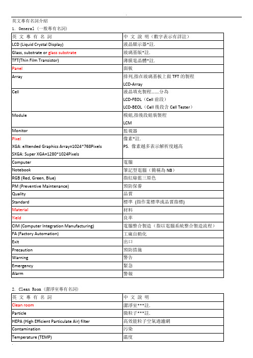
英文專有名詞介紹1. General (一般專有名詞)2. Clean Room (潔淨室專有名詞)3. Factory Automation (工廠自動化專有名詞)*註.OPI(Operation POSEIDON Instruction)海神生產作業系統專有名詞介紹6.Cell段製程專有名詞介紹7. 日常使用的英文名詞通用术语Array Line进行Thin Film, Photo, Etch工艺的生产Line是Array Line,主要制造Glass上面TFT (Thin Film Transistor) 结构。
Cell Line进行PI Coating, Rubbing, Filling, Seal/TR印刷工艺等生产Line是Cell Line,主要生产TFT-LCD Cell状态产品的过程。
Module Line是用TCP (Tape Carrier Package) 将PCB与CELL进行连接,并使用BEZEL进行组装的Ass’y工艺等的生产Line ,是生产TFT Module产品的过程。
LCD Liquid Crystal Display的简称。
用电场、磁场等外部影响,改变液晶分子排列,改变液晶分子结构的光学特性后,利用其明暗效果的显示元件.TFT-LCD 在形成FET (Field Effect Transistor)结构的TFT Glass与Color Filter之间注入液晶而制成的显示元件,使用于Note Book PC、Monitor、中小型TV 等。
Polarizer (POL)偏光片将入射光分为2个直交的偏光,透射其中特定方向的光线,吸收或分散别的光线后,将透射光变为偏振光的高分子FilmBacklight (B/L)为了给LCD提供光源,在Panel后部组装的发光部件,有EL, LED, CCFL 等。
Color Filter (C/F) 制造Color液晶显示元件时使用的主要原材料,指按一定的顺序排列了Red,Green,Blue像素的薄膜。
- 1、下载文档前请自行甄别文档内容的完整性,平台不提供额外的编辑、内容补充、找答案等附加服务。
- 2、"仅部分预览"的文档,不可在线预览部分如存在完整性等问题,可反馈申请退款(可完整预览的文档不适用该条件!)。
- 3、如文档侵犯您的权益,请联系客服反馈,我们会尽快为您处理(人工客服工作时间:9:00-18:30)。
Solomon Systech LimitedSEMICONDUCTOR APPLICATION NOTEThis document contains information on a new product. Specifications and information herein are subject to change without notice. Flickering in TFT Rev 1.1 P 1/10 Sep 2008 Copyright © 2008 Solomon Systech LimitedApplication NoteSolution of Flickering in TFTContents1INTRODUCTION (3)2FLICKERING CAUSES (3)3ILLUSTRATIONS (3)3.1U NSTABLE P OWER S UPPLY (3)3.2U N-MATCHED G AMMA IN P OSITIVE AND N EGATIVE F RAME (4)3.3L OW R EFRESH RATE (6)3.5U N-OPTIMIZED V COM LEVEL (7)4IMPROVEMENTS (8)4.1D RIVER L EVEL (8)4.2P ANEL L EVEL (8)Solomon Systech Sep 2008 P 2/10Rev 1.1 Flickering in TFTApplication Notes on LCD’s Flickering (TFT Series)1IntroductionFlickering is the opposing changes in intensity of luminosity periodically that can be observed by human eyes. This is usually caused by flashing, or contrast patterns that oscillate at a frequency which makes viewers believe the image is moving or changing. In TFT module design, there are different causes for this issue and can be avoided with various techniques in TFT panel and driver IC design.2Flickering CausesHere are some critical areas that may lead to flickering.a.Unstable power supplyb.Un-matched gamma in Positive and Negative framec.Low refresh rated.Un-optimized Vcom level3Illustrations3.1Unstable Power Supplyz Figure 3-1 shows the basic pixel structure in the TFT panels.z The equivalent circuit model is shown in Figure 3-2.z Voltage applies to the LC (Vlc) is controlled by the Vgate, Vsource and Vcom. When Vgate is driven to high, source voltage (Vsource) is applied to the LC display with respect to Vcom as shown in Figure3-2.z Figure 3-3 shows the ideal voltage level of the control signals in the positive and negative frame for the same color. Notice that the Vlc is equal to the differences between the Vsource and Vcom and shouldbe unchanged for the same color level in the positive and negative frame.z Figure 3-4 shows an example that the Vsource level is affected when data is written into the memory in video mode. In this example, the video data transmission frequency is 30Hz and the frame frequency is60Hz. Video data will be transmitted and induced a peak current switching periodically in the negativeframe. If the ITO resistance is too high and the power supply is unstable, Vlc will be affected andbecame unmatched in positive and negative frame. Flickering will occur if this happens periodically.Figure 3-1 Pixel Structure in TFT Panel Figure 3-2 Pixel circuit model in TFT PanelFlickering in TFT Rev 1.1P 3/10 Sep 2008 Solomon SystechPower3.2Un-matched Gamma in Positive and Negative Framez Figure 3-5 shows the ideal Vsource level (V0-V7) at different gray scale voltage in the positive and negative frame with AC Vcom.z Same color will be displayed when the voltage level of V0 in the positive frame and the negative frame is the same. If they are mismatched, LC voltage will be affected as shown in Figure 3-6 and flickeringoccurs.z Gamma is used to measure the luminance against the grey scale level voltage.z Ideally both gamma curves of the positive and negative frame should be the same if the gray scale voltage is matched. If they are mismatched, the gamma curves are different as shown in Figure 3-7. Solomon Systech Sep 2008 P 4/10Rev 1.1 Flickering in TFTFigure 3-7 Gamma Curve of Unmatched Positive and Negative Frame z With different inversion schemes as shown in Figure 3-8, the severity of the flickering will be different.z‘+’ and ‘-’ represent the polarity of the Vsource level as shown in the positive frame in Figure 3-6. Flickering in TFT Rev 1.1P 5/10 Sep 2008 Solomon Systechz In Frame inversion, the polarity of the Vsource of the whole panel is the same in each frame and will e z the column Vsource are different z flickering is switch polarity in every frame. Flickering becomes noticeable by the customers if positive and negativ frame is mismatched. This kind of flickering is “Frame Flickering”.In Line inversion and column inversion, the polarities of the row and respectively in each frame. If the positive and negative frame is mismatched, the whole row or column of line will appear moving to the viewers. This kind of flickering is “Line Flickering”.In Dot Inversion scheme, each pixel is displayed in different polarity in each frame and3.3 Low Refresh ratee frequency of the gate opening (N). When the gate opens, source voltage is e z e gate closing period. Moreover, there is a device leakage is occurs due to this voltage drops.z R fresh rate controls the applied to the source line of LCD and charges up the Clc and Cst to show the color. Once the gate is closed, the color will depend on the charged up value of the capacitors, LC capacitor (Clc) and Storag Capacitor (Cs ) as shown in Figure 3-2.Clc & Cs will have a leakage current in th current from the source to the drain of the transistor and it is panel-by-panel based. If the refresh rate low or device leakage is large, the leakage current will be significant enough to affect the voltage on LC. Once the gate is activated, the Clc and Cs is charged up again as shown in Figure 3-9. FlickeringSolomon SystechSep 2008P 6/10Rev 1.1Flickering in TFT3.4z scale level is depended on the applied LC voltage (Vsource –Vcom). panel, the required Vcom voltage can be slightly differ.Un-optimized Vcom levelAs shown in Figure 3-3, the gray z Due to the offset within each LCD z This offset can cause the unmatched LC voltage in the positive and negative frame as shown in Figure 3-10 and create the appearance of flicker within the display.Flickering in TFT Rev 1.1P 7/10Sep 2008Solomon Systech3Improvements4.1Driver LevelVCIX3 Power Architecturez In the future, SSL TFT driver products will be added VCIX3 as reference to generate Vcom waveform.This increases Vcom voltage level stability, especially in high loading panel. (panel size >3.5 inch).z In these drivers, VCIX3 is also the source to generate VLCD. More stable VLCD will increase source voltage reference output stability. This minimizes source voltage output distortion in high loadingpattern (e.g. plain grey).Gamma Controlz In SSL TFT driver products, user command set for gamma control is provided. User can use these to tune the gamma curve of the positive and negative frame and eliminate the flickering. Driver ICs withvarious inversion schemes are also available, e.g. SSD2220, SSD1297 with line inversion, SSD2125with dot inversion for user to choose based on their application needed.VCOM Level Turningz Adjust the Vcomh level on the panel-by-panel can eliminate the flickering. In SSL TFT driver products(e.g. SSD2118, SSD2123), Multiple-Time Programming (MTP) function and user command sets areprovided to user to tune the Vcomh value.4.2Panel Levelz Maximum supply power can be achieved by careful ITO layout and decreasing the ITO resistance.Suggested ITO resistance of the power pin (e.g. VCI, VCIX2) should be less than or equal to 5 ohms.Increasing the power pin counts and pad width is also recommended. Figure 3-2 below shows anexample of ITO resistance requirement on input pins.z Stable power supply can be achieved by using the appropriated capacitors on the FPC. In SSL TFT drivers, recommended capacitors values are stated in the datasheet for the best performance as shown inFigure 3-1.Solomon Systech Sep 2008 P 8/10Rev 1.1 Flickering in TFTPins Recommended CapacitorValueVCIX2 2.2uFVCIM 1.0~2.2uFVGH 1.0~2.2uFVGL 1.0~2.2uFVCI 1.0~2.2uFC1N/C1P 0.1~0.22uFC2N/C2P 0.1~0.22uFC3N/C3P 0.1~0.22uFCXN/CXP0.1~0.22uFCYN/CYP0.1~0.22uFFigure 3-1 Recommended Capacitors ValuesFlickering in TFT Rev 1.1P 9/10 Sep 2008 Solomon SystechPins Recommended ITO ResistanceVCIX2 5OHMVCI 5OHMVGH 10OHMVGL 10OHMVCIM 10OHMVCOMH 5OHMVCOML 5OHMVCHS 5OHMFigure 3-2 Recommended ITO ResistanceSolomon Systech Sep 2008 P 10/10 Rev 1.1 Flickering in TFT。