吉诺通使用手册(英语版)
ABLETON MASCHINE+ 中文操作手册说明书

MASCHINE + 中文操作手册目录1.免责声明 (1)2.前言 (2)3.欢迎使用MASCHINE+ (3)3.1. MASCHINE 文档 (3)3.2. 文档规范 (4)3.3. 重要名词和概念 (4)3.4. 独立运行模式和控制器模式 (6)4.连接MASCHINE+ (8)4.1. 设置示例 (8)4.1.1. 连接有源监听音箱 (8)4.1.2. 连接监听耳机 (9)4.1.3. 连接线路输入设备 (10)4.1.4. 连接动圈话筒 (10)4.2. 连接Wi-Fi (12)4.2.1. 断开Wi-Fi连接 (12)4.2.2. 飞行模式 (12)4.3. 通过Ableton Link同步MASCHINE+ (12)4.3.1. 连接Ableton Link (13)4.3.2. 加入或离开Link会话 (13)4.4. 连接外部MIDI设备 (14)4.4.1. 连接外部MIDI设备 (14)4.4.2. 与外部MIDI时钟同步 (15)4.4.3. 发送MIDI时钟 (15)4.5. 连接踏板 (15)4.6. MASCHINE+和计算机的连接 (16)4.7. 将MASCHINE+作为MIDI设备使用 (16)4.8. 使用多台MASCHINE设备 (16)5.MASCHINE+简介 (18)5.1. 主面板 (18)5.1.1.控制区 (19)5.1.2.编辑区 (20)5.1.3. 演奏区 (21)5.1.4. 编组区 (22)5.1.5. 走带控制区 (23)5.1.6. 打击垫区 (24)5.2. 侧面板 (28)5.3. 背板 (28)6.常用操作 (30)6.1. 四向编码器 (30)6.2. 模式和模式锁定 (30)6.3. 撤销(Undo)和重做(Redo) (32)6.4. 定位一个编组或声音 (32)6.5. 在Master/Group/Sound之间切换 (33)6.6. 通道属性/插件/参数换页的导航操作 (33)6.7. Volume(音量)、Swing(摇摆)和Tempo(拍速)的调节 (34)6.8. 智能触条 (35)6.8.1. 弯音轮模式(Pitch Mode) (36)6.8.2. 调制轮模式(Mo dulation Mode) (36)6.8.3. 音符模式(Notes Mode) (36)6.9. 输入文字 (37)7. M ASCHINE+上手操作 (38)7.1. 使用音色库文件 (38)7.1.1. 下载音色库文件 (38)7.1.2. 产品的更新 (38)7.1.3. 在库中查看已安装的产品 (38)7.2. 使用File(文件)菜单 (39)7.2.1. 传输文件到SD卡 (40)7.2.2. 从SD卡打开文件 (40)7.2.3. 保存工程文件 (41)7.2.4. 保存编组(Group)文件 (41)7.2.5. 保存声音(Sound)文件 (42)7.2.6. 导出音频文件 (42)7.3. Settings(设置)简介 (45)7.3.1. General(通用)设置 (46)7.3.2. Audio(音频)设置 (48)7.3.3. MIDI 设置 (49)7.3.4. System(系统)设置 (51)7.3.5. Library(库)设置 (52)7.3.6. Hardware(硬件)设置 (52)7.3.7. Network(网络)设置 (54)7.3.8. About(关于)设置 (54)8. 使用浏览器 (56)8.1. 浏览库文件 (56)8.2. 通过四向编码器浏览库文件 (57)8.2.1. 选择产品类型、产品、音色库、子音色库 (57)8.3. 访问用户内容(User Content) (59)8.4. 收藏夹筛选器 (60)8.4.1. 将一个项目加入收藏夹 (60)8.4.2. 从收藏夹中移除一个项目 (60)8.5. 快速浏览功能 (61)8.6. 其它浏览工具 (62)8.6.1. 自动载入选定的文件 (62)8.6.2. 乐器预置的预听 (63)8.6.3. 采样的预听 (63)8.6.4. 载入带有Pattern的编组 (63)8.6.5. 载入带有信号路由的编组 (64)9. 管理声音、编组、工程 (65)9.1. 声音(Sounds)、编组(Groups)、Master(母线)简介 (65)9.1.1. 声音(Sound)、编组(Group)和Master (母线) (65)9.1.2. 声音和编组处理的异同点 (66)9.1.3. 选择多个声音或编组 (66)9.2. 管理声音 (69)9.2.1. 载入声音 (69)9.2.2. 声音的预听 (69)9.2.3. 声音插槽的重命名 (69)9.2.4. 更改声音的颜色 (70)9.2.5. 保存声音 (70)9.2.6. 声音的复制和粘贴 (70)9.2.7. 移动声音 (71)9.2.8. 重置声音插槽 (71)9.3. 管理编组 (71)9.3.1. 创建编组 (71)9.3.2. 载入编组 (72)9.3.3. 编组重命名 (72)9.3.4. 更改编组颜色 (73)9.3.5. 保存编组 (73)9.3.6. 编组的复制和粘贴 (73)9.3.7. 移动编组 (74)9.3.8. 删除编组 (74)10.插件的操作 (75)10.1. 插件简介 (75)10.1.1. 插件基础 (75)10.1.2. 插件的载入、移除、替换 (77)10.1.3. 通过声音的第一个插件插槽指定声音角色 (78)10.1.4. 浏览插件插槽 (78)10.2. 插件参数的调节 (80)10.3. 插件插槽的旁通操作 (80)10.4. 旁链(Side-Chain)的使用 (81)10.5. 插件的移动 (81)10.6. 采样器插件 (82)10.6.1. 第1页: Voice Settings / Engine (82)10.6.2. 第2页: Pitch / Envelope (83)10.6.3. 第3页: FX / Filter (85)10.6.4. 第4页: Modulation (86)10.6.5. 第5页: LFO (87)10.6.6. 第6页: Velocity / Modwheel (88)10.7. 使用音频插件 (89)10.7.1. 将Loop载入到音频插件 (92)10.7.2. 使用Loop 模式 (92)10.7.3. 使用Gate 模式 (93)10.8. 使用 Drumsynths (93)10.8.1. Drumsynths ‒常用 处理 (94)10.8.2. Drumsynth中的引擎 (94)10.8.3. 常用参数的组织方式 (94)10.8.4. 共用参数 (95)10.8.5. 力度响应 (95)10.8.6. 音高范围、音高调节和MIDI音符 (96)10.9. 使用 Bass Synth (96)10.9.1. Bass Synth简介 (97)10.9.2. Bass Synth 参数 (97)10.10. 使用NI插件 (98)10.10.1. 使用 VST/AU 插件参数 (99)10.10.2. 使用NI插件预置 (99)10.10.3. 多通道输出插件和多音色插件 (100)11.Patterns的录制 (101)11.1. 设置录制选项 (101)11.1.1. 设置拍速 (102)11.1.2. 设置 Step Grid (102)11.1.3. Pattern长度调节 (103)11.2. 弹奏和编制鼓点 (103)11.2.1. 载入鼓组 (103)11.2.2. 实时录制鼓点节拍 (105)11.2.3. 使用步进模式构建鼓点音序 (107)11.2.4. 加入Swing变化 (108)11.2.5. 应用Groove (108)11.2.6. 阻断音符(Choke)功能 (109)11.3. 创建旋律与和声音 (110)11.3.1. 载入一个乐器 (110)11.3.2. 实时录制旋律与和声音 (111)11.3.3. 使用步进音序器编辑旋律与和声 (111)11.3.4. 选择音阶与和弦 (111)11.3.5. 音阶与和弦参数 (113)11.3.6. 创建琶音 (120)11.3.7. 使用智能触条弹奏音符 (123)11.4. 录制调制内容 (123)11.4.1. 在Step模式下录制调制内容 (124)11.4.2. 哪些参数可以被调制? (124)11.5. 锁定快照功能 (125)11.5.1. 锁定快照 (125)11.5.2. 扩展锁定功能 (125)11.5.3. 快照更新 (126)11.5.4. 快照的调取 (126)11.5.5. 不同快照之间的变换 (126)11.5.6. 快照的删除 (127)12.Patterns和Clips的操作 (128)12.1. Patterns的操作 (129)12.1.1. 删除事件或音符 (129)12.1.2. 在Step模式中快速编辑 (130)12.1.3. 删除编组和声音 (131)12.1.4. Pattern的量化处理 (132)12.1.5. Pattern的加倍处理 (132)12.1.6. 清除Pattern中的事件 (133)12.1.7. 删除Pattern (133)12.1.8. 复制Pattern (133)12.1.9. Pattern的移调 (133)12.1.10. 事件/音符的剪切、复制、粘贴 (133)12.1.11. 为Patterns加入变奏 (134)12.1.12. 声音的复制 (136)12.1.13. 编组的复制 (137)12.2. Clips的操作 (137)12.2.1. 创建一个Clip (137)12.2.2. 删除一个Clip (138)12.2.3. Clip的加倍 (138)12.2.4. Clip的复制 (138)12.2.5. Clip的清除 (138)12.2.6. 调节Clip的长度 (139)12.2.7. 调节Clip的起始位置 (139)12.2.8. Clip的位置移动 (140)12.2.9. 将Scenes作为Clip插入到Arrangement中 (140)13. 音频路由、远程控制及Macro控制 (141)13.1. 使用MIDI控制 (141)13.1.1. 通过Sound(声音)发送MIDI数据 (142)13.2. 音频路由 (143)13.2.1. 发送外部音频信号到声音 (144)13.2.2. 配置声音和编组的主输出 (145)13.2.3. 为声音和编组设置辅助输出 (147)13.2.4. 配置Master和Cue Output (147)13.2.5. 单声道音频输入 (148)13.2.6. 通过MIDI音符来触发声音 (149)13.3. 利用Macro控制创建自定义参数集 (150)13.3.1. Macro 控制简介 (151)14. 混音控制 (152)14.1. 混音模式下的通道导航操作 (152)14.2. 在混音模式中调节通道的电平和声像 (153)14.3. 混音模式中的Mute和Solo操作 (154)14.4. 混音模式下的插件图标 (154)15. 使用效果器 (156)15.1. 效果器列表 (156)15.2. 为声音、编组或Master应用效果器 (157)15.2.1. 添加效果器 (157)15.2.2. 效果器的其它操作 (158)15.2.3. 使用旁链输入 (159)15.3. 为外部音频应用效果器 (160)15.3.1. 第一步: 配置MASCHINE+ 的音频输入端口 (160)15.3.2. 第2步:设置可接收外部输入的声音 (161)15.3.3. 第3步: 载入效果器处理输入信号 (162)15.4. 创建发送式效果器 (163)15.4.1. 第1步: 设置声音或编组为发送式效果器 (163)15.4.2. 第2步: 将音频路由到发送式效果器 (165)15.5. 创建多功能效果器 (166)16. 使用演出效果器 (168)16.1. 演出效果器列表 (168)16.2. 使用演出效果器 (168)16.3. 演出效果器的自动控制 (169)17. 工程的编排 (170)17.1. Ideas视图和Song视图的切换 (170)17.2. 使用Ideas视图 (170)17.2.1. 使用Scene模式 (171)17.2.2. 创建一个新的Scene (171)17.2.3. 为Scene分配、删除Patterns (171)17.2.4. 在Idea视图中删除Pattern (172)17.2.5. 选择一个Scene (172)17.2.6. 删除Scene (173)17.2.7. 复制Scene (173)17.2.8. 选择Scene 库 (173)17.2.9. 创建和删除Scene库 (173)17.2.10. Scene的唯一化 (174)17.2.11. 将Scene添加到Arrangement (174)17.2.12. 为Scene更改颜色 (174)17.3. 使用Song视图 (174)17.3.1. 创建段落 (175)17.3.2. 为段落分配Scene (175)17.3.3. 选择段落 (175)17.3.4. 创建、删除段落库 (176)17.3.5. 选择段落库 (176)17.3.6. 移动段落 (176)17.3.7. 调整段落长度 (177)17.3.8. 复制段落 (177)17.3.9. 删除段落 (178)17.3.10.段落的自动长度模式 (178)17.4. Arrange Grid (179)17.5. Quick Grid (179)18. 采样和采样映射 (180)18.1. 打开采样编辑器 (180)18.2. 录制音频简介 (180)18.2.1. 打击录制页 (180)18.2.2. 指定录音乐源 (181)18.2.3. 选择录音模式 (182)18.2.4. 输入信号的监听 (183)18.2.5. 录音的Arm、Star t、Stop操作 (183)18.2.6. 利用踏板录制音频 (185)18.2.7. 检测您的录音 (185)18.3. 采样的编辑 (187)18.3.1. 使用编辑页 (187)18.3.2. 音频编辑 (188)18.4. 采样切片功能简介 (191)18.4.1. 采样切片 (191)18.4.2. 打开Slice(切片)页 (191)18.4.3. 调整切片设置 (192)18.4.4. 实时切片处理 (194)18.4.5. 删除所有切片 (194)18.4.6. 手动调节切片 (194)18.4.7. 应用切片 (196)18.4.8. 导出单个切片 (197)18.5. 映射采样到键区 (197)18.5.1. 打开键区(Zone)页 (197)18.5.2. 编辑键区 (198)18.5.3. 添加采样到采样映射 (201)19. 技术支持 (202)19.1. 如何获得技术支持 (202)19.2. 用户论坛 (202)20. 术语汇总 (203)免责声明1.免责声明 本文档中的信息如有更改,恕不另行通知,文档中的内容并不代表Native Instruments公司的承诺。
吉诺通使用手册(英语版)

Package leaflet: Information for the userGeloMyrtol® forte300 mg, gastro-resistant capsules, softActive substance:Myrtol standardized to at least 75 mg limonene, 75 mg cineole and 20 mg alpha-pinene.Read all of this package leaflet carefully because it contains important information for you.This medicinal product is available without prescription. However, you still need to takeGeloMyrtol® forte carefully to get the best results from it.- Keep this leaflet. You may need to read it again.- Ask your pharmacist if you need more information or advice.- You must contact a doctor if your symptoms worsen or do not improve after 10 days.- If any of the side effects affects gets serious or if you notice any side effects not listed in this leaflet, please tell your doctor or pharmacist.In this leaflet:1. What GeloMyrtol® forte is and what it is used for2. Before you take GeloMyrtol® forte3. How to take GeloMyrtol® forte4. Possible side effects5. How to store GeloMyrtol® forte6. Further informationGeloMyrtol® forte is available in packs of 20, 50 and 100 gastro-resistant capsules, soft.1. What GeloMyrtol® forte is and what it is used forEffect: GeloMyrtol® forte is a herbal medicine. It liquefies mucus and promotes its transport, makes mucus easier to cough up and reduces inflammation.Used to treatacute and chronic bronchitis and inflammation of paranasal sinuses (sinusitis)2. Before you take GeloMyrtol® forteDo not take GeloMyrtol® forte:- if you have an inflammatory disorder of the stomach, gut or bile duct region, or if you have a severe liver disorder;- if you are known to be allergic (hypersensitive) to eucalyptus oil, sweet orange oil, myrtle oil, lemon oil or cineole (the main constituent of eucalyptus oil), or to any of the other ingredients.Take special care with GeloMyrtol® forte:- if your symptoms should persist or get worse, or if you develop shortness of breath or fever, or if you start coughing up mucus containing blood or pus-like matter, you should consult a doctor immediately.- if you suffer from bronchial asthma, whooping cough or other respiratory diseases accompanied by manifest hypersensitivity of the respiratory system, always consult your doctor before you take GeloMyrtol® forte.Taking other medicinesInform your doctor or pharmacist if you take/apply other medicines or did so recently even if it is/was a non-prescription product.Pregnancy and breast feedingBefore you take any medicine ask your doctor or pharmacist.- Pregnancy:Animal studies do not indicate direct or indirect harmful effects on the foetus. Caution is basicallyadvised when taking it during pregnancy.- Breast feeding:Due to the liposoluble properties of the active ingredient it can be assumed that its constituents are also present in the breast milk at minor concentrations. So far there has been no indication of any risk when using GeloMyrtol® forte during the time of breast feedingDriving and using machinesNo special precautions are required.3. How to take GeloMyrtol® forteAlways take GeloMyrtol® forte exactly as directed in this leaflet. You should check with your doctor or pharmacist if you are not sure.Unless otherwise prescribed by your doctor, the usual dose is:Adults, juveniles and children from the age of 12 with acute inflammatory symptoms should take 1 gastro-resistant soft capsule 3 – 4 times a day. Patients with chronic symptoms should take 1 gastro-resistant capsule 2 or 3 times a day. This dose is also recommended for a long-term treatment.For children the following doses of GeloMyrtol® forte are recommended:Age group Under 6(approx. 13 – 19 kg)From 6 to 10 years(approx. 20 – 29 kg)From 10 to under 12years(approx. 30 – 43 kg)Acute symptoms 1 x 1gastro-resistant capsule2 x 1gastro-resistant capsule2 –3 x 1gastro-resistant capsuleChronic symptoms 1 x 1gastro-resistant capsule1 –2 x 1gastro-resistant capsule2 x 1gastro-resistant capsuleDirections for useGeloMyrtol® forte capsules should be taken 30 minutes before a meal, with plenty of cold liquid. The last dose of the day can be taken before bedtime.Duration of treatmentThe duration of GeloMyrtol® forte treatment depends on the medical condition. For chronic respiratory diseases a long-term treatment is possible.If you take more GeloMyrtol® forte than you shouldPlease inform your doctor. He/she can then decide on any measures that may be required. The side effects listed below may occur in a more exaggerated form.If you forget to take GeloMyrtol® forteDo not take a double dose to make up for a forgotten dose. Continue taking GeloMyrtol® forte at your next scheduled time, as prescribed by your doctor or as described in the dosage instructions.4. Possible side effectsLike all medicines GeloMyrtol® forte can cause side effects, although not everybody gets them. The frequency of occurrence of side effects is based on the following categories:Very common: more than one men in 10 Common: 1 to 10 men in 100Uncommon: 1 to 10 men in 1,000 Rare: 1 to 10 men in 10,000Very rare: less than 1 men in 10,000Not known: Frequency not assessable based on the data availablePotential side effects:In uncommon cases, gastrointestinal complaints may occur, in the stomach/upper abdomen region, for example, in rare cases nausea, vomiting or diarrhoea. There have been rare reports of hypersensitive reactions (e.g. rash, itching facial swelling, shortness of breath and circulatory problems). In very rare cases kidney stones or gallstones present may become dislodged.Inform your doctor or pharmacist if one of the listed side effects affects you considerably or you notice side effects not indicated in this leaflet.5. How to store GeloMyrtol® forteKeep out of the reach and sight of children.Do not use GeloMyrtol® forte after the expiry date which is stated on the blister pack and outer carton. The expiry date refers to the last day of the month.Storage conditions:Store in the original package, in order to protect it from moisture. Do not store above 25°C.6. Further informationWhat GeloMyrtol® forte contains:The active substance is:1 gastro-resistant soft capsule contains 300 mg Myrtol standardized to at least 75 mg limonene, 75 mg cineole and 20 mg alpha-pinene.Other ingredients are:refined rapeseed oil; gelatin; glycerol 85%; sorbitol liquid 70% (non-crystallising); hypromellose acetate succinate; triethyl citrate; sodium laurilsulfate; talc; dextrin; glycyrrhizic acid, ammonium saltHow GeloMyrtol® forte looks like and contents of the pack:GeloMyrtol® forte are long, uncoloured, naturally cloudy soft capsules.The following pack sizes are available:Pack of 20 gastro-resistant capsules, softPack of 50 gastro-resistant capsules, softPack of 100 gastro-resistant capsules, softMarketing authorisation holder and manufacturerG. POHL-BOSKAMP GmbH & Co. KG Tel.: +49 (0)48 26 59 0Kieler Strasse 11 Fax: +49 (0)48 26 59 10925551 Hohenlockstedt E-mail: i nfo@pohl-boskamp.deGermany Internet:www.pohl-boskamp.deLatest revision of these instructions in January 2009。
SURGE XL 说明书

WARNING:Do not change the coloration and markings to make it look more like a firearm. That is dangerous and may be a crime. Buyer and user have the duty to obey all laws about the use and ownership of this toy. Adult supervision required. Misuse or careless use may cause serious injury, especially to the eye.Eye protection must be used by the user and any person within range. May be dangerous up to 100 feet. Read owner’s manual before using.Recommended for users 9 years or older, and may be more appropriate for users 12 years and older.STEP 1 - HYDRATE YOUR GELLETS® !! IMPORTANT !!Gellets™ must be submerged in water for at least two hours to fully expand to size. They also need to haveplenty of water to absorb (this is very important) - you’ll know there was plenty of water if after two hours the Gellets are still submerged in the water. Failing to completely hydrate Gellets will cause your Gel Blaster®to seem crappy.Note: Make sure that the Gellets are prepared in an adequate sized container. Gellets will expand ten times their original size. Store hydrated Gellets away from the elements and direct sunlight.ONE GALLON OF WATER MAKES 10,000 GELLETS®!HOW TO STORE YOUR GELLETS®Keep hydrated Gellets® ready for use I N S T R U C T I O N SMORE INFO ABOUT GELLETS®• Gellets® expand 10x their original size!©2022 Gel Blaster, Inc. All Rights Reserved.Gel Blaster, Inc. warrants this Gel Blaster® for a period of one month from the date of consumer purchase to be free from defects in material and workmanship. Gel Blaster, LLC’s obligation under this warranty is limited to repair or replacement of the purchased product only (although Gel Blaster, LLC may determine to issue a refund, in its sole and exclusive discretion), and under no circumstances shall Gel Blaster, LLC be liable for any loss, damage, injury, cost of repair, consequential damages, incidental damages, or punitive, treble, or exemplary damages of any kind in connection with the sale, use, failure, or repair of any product purchased from Gel Blaster, LLC, even if such damages are caused by the negligence of the released party, whether sole or in combination with others. You hereby waive any claim by an insurance carrier or other person or entity by way of subrogation, and you hereby assign any and all such subrogation claims to Gel Blaster, LLC.Gel Blaster, LLC disclaims any warranty of fitness for a particular purpose and any implied warranty of merchantability. All implied warranties are hereby disclaimed, and you agree that the only warranty provided by Gel Blaster, LLC to you is the above.Gel Blaster, LLC’s liability for any and all claims arising out of or connected with the Gel Blaster® shall be limited to the amount paid by consumer for the product plus the sum of $100.00.You and Gel Blaster, LLC agree to mandatory, binding arbitration for any and all claims or causes of actionbetween the parties arising out of or in connection with your purchase or use of the Gel Blaster®, its accessories, or otherwise with respect to any claims between you and Gel Blaster, LLC. The arbitration shall take place under the rules of the American Arbitration Association, Consumer Arbitration Rules, before a single arbitrator. The Arbitration shall take place in Dallas, Texas. You understand and agree that you are waiving your rights to a trial by jury. You agree that any claim you have or may ever come to have against Gel Blaster, LLC must be submitted on an individual basis, and you hereby waive the right to assert such claim collectively, such as in a class or mass action. As a condition precedent to filing arbitration, you must contact Gel Blaster, LLC with any claim or dispute, which must be mediated before a mutually agreeable mediator in Dallas, Dallas County, Texas.You agree to the foregoing terms when you first charge or otherwise seek to use your Gel Blaster® or its accessories.LIMITED WARRANTY, SUBROGATION WAIVER, WAIVER AND RELEASE, BINDING AGREEMENT TO ARBITRATE, CLASS ACTION WAIVER** The Gel Blaster® SURGE XL provides hours of playtime per charge using a powerful lithium polymer battery! But with that power comes the responsibility to take care of your battery. Abuse,neglect,ormisusecanruinyourbattery,shortenyourplaytime,orevencauseafire.Ifyourblasterwon'ttakeacharge,ceaseuseandcharging!*****************************Q: My hopper & feedneck keep sliding off and won’t feed the Gellets into my Gel Blaster®?A: Please make sure your feedneck is oriented correctly - the green triangles of your blaster and feedneck should be aligned. If installed correctly, the hopper and feedneck will click & lock in place.Q: My Gellets aren’t shooting correctly and are rolling out of my Gel Blaster’s barrel?A: The Gellets might not be fully hydrated. To make sure your Gellets are fully hydrated, please allow your Gellets to be submerged in water for a minimum of two hours before playing.Q: My Gel Blaster® seems jammed?A: Your Gel Blaster® will rarely get jammed, but if this is the case, please make sure to turn the ON/OFF switch to the OFF position. Now proceed to check the tip and barrel of the Gel Blaster. If debris is found in your Gel Blaster, remove your hopper & feedneck and spray canned air directly into the barrel forcing the debris to come out of the tip of the blaster. If the debris is still stuck, use a pipe cleaner to force the remainder out of the tip of the blaster. Never push the debris from the tip/front of the Gel Blaster towards the back, that will only jam your Gel Blaster more.。
JEOL2010F_TEM_Instructions
TABLE OF CONTENTS
PERSONAL and INSTRUMENT SAFETY ............................................................... 2 TEM SESSION PREPARATION ............................................................................... 3 Log/Invoice .................................................................................................... 3 Prepare Refrigerant Tank............................................................................... 3 Sample Cleaning Procedure........................................................................... 3 Presets on Microscope ................................................................................... 3 Specimen Holder Insertion ............................................................................ 4 TEM ALIGNMENT PROCEDURE ........................................................................... 5 Illumination.................................................................................................... 5 Condenser Aperture Centering ...................................................................... 5 Condenser Lens Astigmatism Correction ...................................................... 5 Standard Focus: Z-Height .............................................................................. 5 Tilt to Zone Axis............................................................................................ 6 Gun Shift........................................................................................................ 6 Gun Tilt.......................................................................................................... 6 Condenser Deflector Shift Interlock Balance ................................................ 6 Beam Tilt (Voltage Centering) ...................................................................... 7 Intermediate Lens Astigmatism Correction ................................................... 7 Projection Lens Centering.............................................................................. 7 Condenser Deflector Tilt Interlock Balance .................................................. 7 Alignment Check ........................................................................................... 8 Objective Lens Astigmatism Correction........................................................ 8 Objective Lens Focus..................................................................................... 9 SPECIMEN HOLDER REMOVAL.......................................................................... 10 TEM SESSION SHUT DOWN PROCEDURE ........................................................ 11 INSTRUCTION REFERENCE PHOTOGRAPHS................................................... 12 APPENDICES ........................................................................................................... 14 A Variable Condenser Aperture ...................................................................... 14 B GIF Setup and Alignment ............................................................................ 15 C Dispensing Liquid Nitrogen......................................................................... 18 D Exchanging JEOL 2010F Camera Film....................................................... 19 E Fischione Plasma Cleaner Instructions ........................................................ 20 F Goniometer Plug Insertion/Removal ........................................................... 22 G Specimen & Holder Decontamination Procedure........................................ 23 H GIF CCD Camera Acquisition Settings....................................................... 24 I GIF Tune Recovery Procedure .................................................................... 27
Ashdown Engineering Jumbo双通道电子吉他放大器说明书

Thank you for purchasing your Ashdown Engineering Amplifier and welcome to the family!We really think you’ve made the right choice and know that this amplifier will give you yearsof great tone and service. It is a machine though and needs to be looked after, please readthrough this user manual which will help you get the most out of your new Amp and keep itrunning as long as some of our happiest and very famous customers.Please register this product online so we can make sure we give you years of customersupport through our friendly in-house service centre.Here is where you need to visit to register your product:/register THANK YOUREGISTER ONLINEINPUTS The Jumbo is a twin channel unit. Channel 1 is for mi-crophone on either jack or XLR inputs, while Channel 2 works for acoustic instrument inputs. The two channels allow both mic and pick-up inputs to be mixed together to give the best possible sound for the acoustic guitar. Alternatively one channel can be used for the guitar and the other for a vocal mic to form a mini PA system.ACTIVE/PIEZO SWITCH The Active / Piezo switch allows channel 2 input to be set for active guitars (those with a built-in preamp) orpassive / piezo instruments where a higher input leveland impedance would be required.PHANTOM POWER This can be switched in to apply a Phantom Power voltage to channel 1 input. This is only for use with suitable capacitor microphones. Do not switch this in for any other type of input to channel 1.VOLUME Once you have set your instrument to the required Eq settings on both the amplifier and the instrument you should then set the VOLUME to the most efficient level to optimise signal to noise ratio.The optimum level is when the input level LED is indicating GREEN most of the time for normal playing, with occasional peaksflashing RED.SHAPE IN / OUT This switch introduces a natural pre-shape to the soundof channel 1 adding a bass boost, a mid cut and a trebleboost that suits both strumming and finger picking stylesof playing. These controls can boost or cut the amountof Treble and Bass of the unit. In their centre position(12 o’clock) they have no effect i.e. the EQ is flat.PHASE This switch reverses the Phase of the signal through theamplifier and is used to help eliminate standing wavefeedback. As such it is very dependent upon the posi-tion of the player relative to the amplifier. If feedback isoccurring try altering the setting of this switch to cancelout the standing wave between you and the amplifier.The Jumbo has a single Notch filter applied to chan-nel 2. This can be switched in and adjusted to elimi-nate ‘body resonance’ feedback of the instrument at higher playing levels. Adjust the Notch Frequency until the body resonance reduces - this will be the optimum position for the instrument. This Notch has a fixed ‘Q’ that has been optimised for acoustic guitar.REVERB Reverb can be added to the sound of the acoustic instrument to make it sound more vibrant and alive. It simulates the sound of the instrument being played in various acoustic environments. The level of reverb to direct sound can be adjusted using the Level control. Switches have been provided to select between Long and Short decay characteristics of both Hall and Plate reverbs. The reverb is situated after the Effects Return and as such can be added to other effects connected via these sockets. When switched in, reverb is added to both channel 1 and 2.AUX The LINE IN jack socket (located at the rear) can be used for any line level signal such as that fromanother pre-amplifier, CD, MP3 etc. There is a AUX LEVEL pot control on the front panel of the amp to set the output level of the line input.The EFFECTS SEND/RETURN facility is a serial effects loop and is situated after the EQ controls and SHAPE switch but before the internal reverb. In this way it is possible to add the internal reverb to the sound returned from any external effects being used.BALANCED D.I. XLR The D.I. XLR socket is a balanced output for Direct In-jection or connection to a low impedance microphone input on a mixing console. This can be used either for recording purposes or for connection to a PA systemfor live performance.WOODSMAN - Jumbo - Front PanelWOODSMAN - Jumbo - Rear PanelsWOODSMAN - Classic - Front Panel WOODSMAN - Parlour - Front PanelINPUTSThe Classic is a twin channel unit. Channel 1 is for mi-crophone on either jack or XLR inputs, while Channel 2 works for acoustic instrument inputs.The two channels allow both mic and pick-up inputs to be mixed together to give the best possible sound for the acoustic guitar. Alternatively one channel can be used for the guitar and the other for a vocal mic to form a mini PA system.ACTIVE & PASSIVE INPUTSThe Active input allows channel 2 input to be set for active guitars (those with a built-in preamp). A Passive input provides passive / piezo instruments where a higher input level and impedance would be required.VOLUMEOnce you have set your instrument to the required Eq settings on both the amplifier and the instrument you should then set the VOLUME to the most efficient level to optimise signal to noise ratio.NOTCH FREQUENCYThe Classic has a single Notch filter applied to channel 2. This can be switched in and adjusted to eliminate‘body resonance’ feedback of the instrument at higher playing levels. Adjust the Notch Frequency until the body resonance reduces - this will be the optimum position for the instrument. This Notch has a fixed ‘Q’ that has been optimised for acoustic guitar.REVERBReverb can be added to the sound of the acousticinstrument to make it sound more vibrant and alive. Itsimulates the sound of the instrument being played invarious acoustic environments.The level of reverb todirect sound can be adjusted using the Level control.AUXThe LINE IN jack socket (located on the front) canbe used for any line level signal such as that fromanother pre-amplifier, CD, MP3 etc. There is a AUXLEVEL pot control on the front panel of the amp to setthe output level of the line input.BALANCED D.I. XLRThe D.I. XLR socket is a balanced output for Direct In-jection or connection to a low impedance microphoneinput on a mixing console. This can be used either forrecording purposes or for connection to a PA systemfor live performance.PHASEThis switch reverses the Phase of the signal throughthe amplifier and is used to help eliminate standingwave feedback.As such it is very dependent uponthe position of the player relative to the amplifier. Iffeedback is occurring try altering the setting of thisswitch to cancel.WOODSMAN - Classic - Rear PanelINPUTSThe Parlour is a twin channel unit. Channel 1 is formicrophone on an XLR input, while Channel 2 works foracoustic instrument Jack inputs.The two channels allowboth mic and pick-up inputs to be mixed together to givethe best possible sound for the acoustic guitar.Alternatively one channel can be used for the guitar andthe other for a vocal mic to form a mini PA system.EQThese controls can boost or cut the amount of TrebleMiddle and Bass of the unit. In their centre position (12o’clock) they have no effect i.e. the EQ is flat.VOLUMEOnce you have set your instrument to the required Eqsettings on both the amplifier and the instrument youshould then set the VOLUME to the most efficient levelto optimise signal to noise ratio.REVERBReverb can be added to the sound of the acousticinstrument to make it sound more vibrant and alive. Itsimulates the sound of the instrument being played invarious acoustic environments. The level of reverb todirect sound can be adjusted using the Level control.AUXThe LINE IN jack socket (located on the top) can beused for any line level signal such as that from anotherpre-amplifier, CD, MP3 etc.WOODSMAN - Parlour - Rear PanelNOTES -SPECIFICATIONSINPUTSActive Input Impedance 10K Ohms Input range 150mV to 10V p-pPassive Input Impedance 3.9M Ohms Input range 300mV to 20V p-pXLR & Jack Impedance 600 Ohms bal. Level -20dB to 0dBEffects Return Impedance 47K Ohms Input level 0dBu nominalOUTPUTSEffects Send Impedance 22K Ohms Level 0dBu nominalD.I. Output 600 Ohms balanced Level -20dBu nominalEQUALISATIONShape (Push Flat) +8dB @ 50Hz & 4kHz, -8dB @ 400Hz, filter slope - 6dB/octaveBass +/-15dB @ 100HzTreble +/-15dB @ 10kHz shelvingFrequency Response -3dB at 28Hz and 28KHzNotch Frequency 70 to 250Hz ‘Q’ = 5Output Power Jumbo - 65w - Classic - 40w - Parlour - 25w。
гу容 lightning strobe说明书
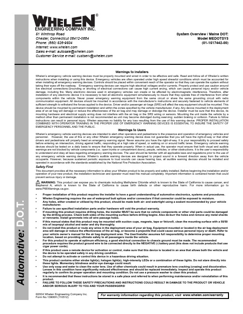
Page 1©2004 Whelen Engineering Company Inc.Form No.13906H (110512)For warranty information regarding this product, visit /warranty•Proper installation of this product requires the installer to have a good understanding of automotive electronics, systems and procedures.•Whelen Engineering requires the use of waterproof butt splices and/or connectors if that connector could be exposed to moisture.•Any holes, either created or utilized by this product, should be made both air- and watertight using a sealant recommended by your vehicle manufacturer.•Failure to use specified installation parts and/or hardware will void the product warranty.•If mounting this product requires drilling holes, the installer MUST be sure that no vehicle components or other vital parts could be damaged by the drilling process. Check both sides of the mounting surface before drilling begins. Also de-burr the holes and remove any metal shards or remnants. Install grommets into all wire passage holes.•If this manual states that this product may be mounted with suction cups, magnets, tape or Velcro®, clean the mounting surface with a 50/50 mix of isopropyl alcohol and water and dry thoroughly.•Do not install this product or route any wires in the deployment area of your air bag. Equipment mounted or located in the air bag deployment area will damage or reduce the effectiveness of the air bag, or become a projectile that could cause serious personal injury or death. Refer to your vehicle owner’s manual for the air bag deployment area. The User/Installer assumes full responsibility to determine proper mounting location, based on providing ultimate safety to all passengers inside the vehicle.•For this product to operate at optimum efficiency, a good electrical connection to chassis ground must be made. The recommendedprocedure requires the product ground wire to be connected directly to the NEGATIVE (-) battery post (this does not include products that use cigar power cords).•If this product uses a remote device for activation or control, make sure that this device is located in an area that allows both the vehicle and the device to be operated safely in any driving condition.•Do not attempt to activate or control this device in a hazardous driving situation.•This product contains either strobe light(s), halogen light(s), high-intensity LEDs or a combination of these lights. Do not stare directly into these lights. Momentary blindness and/or eye damage could result.•Use only soap and water to clean the outer lens. Use of other chemicals could result in premature lens cracking (crazing) and discoloration. Lenses in this condition have significantly reduced effectiveness and should be replaced immediately. Inspect and operate this product regularly to confirm its proper operation and mounting condition. Do not use a pressure washer to clean this product.•It is recommended that these instructions be stored in a safe place and referred to when performing maintenance and/or reinstallation of this product.•FAILURE TO FOLLOW THESE SAFETY PRECAUTIONS AND INSTRUCTIONS COULD RESULT IN DAMAGE TO THE PRODUCT OR VEHICLE AND/OR SERIOUS INJURY TO YOU AND YOUR PASSENGERS!A u t o m o t i v e : Warnings to InstallersWhelen’s emergency vehicle warning devices must be properly mounted and wired in order to be effective and safe. Read and follow all of Whelen’s written instructions when installing or using this device. Emergency vehicles are often operated under high speed stressful conditions which must be accounted for when installing all emergency warning devices. Controls should be placed within convenient reach of the operator so that they can operate the system without taking their eyes off the roadway. Emergency warning devices can require high electrical voltages and/or currents. Properly protect and use caution around live electrical connections.Grounding or shorting of electrical connections can cause high current arcing, which can cause personal injury and/or vehicle damage, including fire. Many electronic devices used in emergency vehicles can create or be affected by electromagnetic interference. Therefore, after installation of any electronic device it is necessary to test all electronic equipment simultaneously to insure that they operate free of interference from other components within the vehicle. Never power emergency warning equipment from the same circuit or share the same grounding circuit with radio communication equipment. All devices should be mounted in accordance with the manufacturer’s instructions and securely fastened to vehicle elements of sufficient strength to withstand the forces applied to the device. Driver and/or passenger air bags (SRS) will affect the way equipment should be mounted. This device should be mounted by permanent installation and within the zones specified by the vehicle manufacturer, if any. Any device mounted in the deployment area of an air bag will damage or reduce the effectiveness of the air bag and may damage or dislodge the device. Installer must be sure that this device, its mounting hardware and electrical supply wiring does not interfere with the air bag or the SRS wiring or sensors. Mounting the unit inside the vehicle by a method other than permanent installation is not recommended as unit may become dislodged during swerving; sudden braking or collision. Failure to follow instructions can result in personal injury. Whelen assumes no liability for any loss resulting from the use of this warning device. PROPER INSTALLATION COMBINED WITH OPERATOR TRAINING IN THE PROPER USE OF EMERGENCY WARNING DEVICES IS ESSENTIAL TO INSURE THE SAFETY OF EMERGENCY PERSONNEL AND THE PUBLIC.Warnings to UsersWhelen’s emergency vehicle warning devices are intended to alert other operators and pedestrians to the presence and operation of emergency vehicles and personnel. However, the use of this or any other Whelen emergency warning device does not guarantee that you will have the right-of-way or that other drivers and pedestrians will properly heed an emergency warning signal. Never assume you have the right-of-way. It is your responsibility to proceed safely before entering an intersection, driving against traffic, responding at a high rate of speed, or walking on or around traffic lanes. Emergency vehicle warning devices should be tested on a daily basis to ensure that they operate properly. When in actual use, the operator must ensure that both visual and audible warnings are not blocked by vehicle components (i.e.: open trunks or compartment doors), people, vehicles, or other obstructions. It is the user’s responsibility to understand and obey all laws regarding emergency warning devices. The user should be familiar with all applicable laws and regulations prior to the use of any emergency vehicle warning device. Whelen’s audible warning devices are designed to project sound in a forward direction away from the vehicle occupants. However, because sustained periodic exposure to loud sounds can cause hearing loss, all audible warning devices should be installed and operated in accordance with the standards established by the National Fire Protection Association.Safety FirstThis document provides all the necessary information to allow your Whelen product to be properly and safely installed. Before beginning the installation and/or operation of your new product, the installation technician and operator must read this manual completely. Important information is contained herein that could prevent serious injury or damage.WARNING: This product can expose you to chemicals including Methylene Chloride which is known to the State of California to cause cancer, and Bisphenol A, which is known to the State of California to cause birth defects or other reproductive harm. For more information go to .System Overview / Maine DOT:Model MEDOTSY3(01-1517442-00)51 Winthrop RoadChester, Connecticut 06412-0684Phone: (860) 526-9504Internet: Salese-mail:*******************CustomerServicee-mail:*******************®ENGINEERING COMPANY INC.WARNING! DISCONNECTING THE VEHICLE BRAKE LAMP CIRCUIT USING ANY SIRENS WITH RELAY OUTPUTS OR SWITCH CONTROLLERS COULD CAUSE VEHICLE OR PROPERTY DAMAGE, SERIOUS INJURY OR EVEN DEATH.DISABLING THIS CIRCUIT IS A VIOLATION OF THE FEDERAL MOTOR VEHICLE SAFETY STANDARD FOR THE THIRD BRAKE LIGHT, AS WELL AS REAR BRAKE LIGHTS.FUNCTIONS THAT BLACK OUT THE REAR BRAKE LIGHTS (SOMETIMES CALLED “BRAKE LIGHT CUT OUT”) MAY INTERFERE WITH THE BRAKE SHIFT LOCK MECHANISM, AND CAUSE THE VEHICLE TO MOVE UNEXPECTEDLY AND DANGEROUSLY. DISCONNECTING THE BRAKE LIGHTS IN ANY WAY IS AT YOUR OWN RISK AND IS NOT RECOMMENDED BY WHELEN.Page 2Page 3S W 1S W 2S W 3C a b l e C l a m pL o c k i n g N u tP r i m a r y S h a f t H o u s i n gP l a s t i c W a s h e rL o c k i n g F i x t u r eL o c k i n g C u f fF l e x T u b eW a r n i n g L i g h t (S i n g l e F l a s h )W a r n i n g L i g h t (M u l t i -F l a s h )B r a k e / T a i l / T u r nB a c k -U pW H TB L KB L KG R N R E D R E D G R N W H TC - W H T /B L K (G R O U ND )A - B L UE (B A C K -U P ) (+12V )H A R N E S SY E L /G R N (L E F T T U R N -B R A K E ) (+12V )B R O W N (T A I L ) (+12V )W H I T E (G R O U N D )W H I T E /B L A C K (G R O U N D )B L U E (B A C K -U P ) (+12V )H A R N E S SY E L /G R N (R I G H T T U R N -B R A K E ) (+12V )B R O W N (T A I L ) (+12V )W H I T E (G R O U N D )W H I T E /B L A C K (G R O U N D )B L U E (B AC K -U P ) (+12V )B -Y E L /G R N (L E F T T R N -B R K ) (+12V )B -Y E L /G R N (R I G H T T R N -B R K ) (+12V )C - W H I T E (G R O U ND )C - W H I TE (G R O U N D )A - B R O W N (T A I L ) (+12V )A - B R O W N (T A I L ) (+12V )G R E E N W H I T ER E D B L A C K +12V M O M E N T A R Y S W I T C H 3+12V S W I T C H 2+12V S W I T C H 1W a r n i n g L i g h t (S i n g l e F l a s h )W a r n i n g L i g h t (M u l t i -F l a s h )B r a k e / T a i l / T u r nB a c k -U pM E D O T S Y 3 / M a i n e D O T / 01-1517442-00F L E X T U B I NG I N S T A L L A T I O N A S S E M B L Y10A M P F U S E G R O U N D+12VH o u s i n gC a b l eC a b l eS I D E V I E WW h i t e p l a s t i c w a s h e r a n d c l a m p f o r s t r a i n r e l i e fW A R N I N G !A l l c u s t o m e r s u p p l i e d w i r e s t h a t c o n n e c t t o t h e p o s i t i v e t e r m i n a l o f t h e b a t t e r y m u s t b e s i z e d t o s u p p l y a t l e a s t 125%o f t h e m a x i m u m o p e r a t i n g c u r r e n t a n d a t t h e b a t t e r y t o c a r r y t h e l o a d . D O N O T U S E C I R C U I T B R E A K E R S W I T H T H I S P R O D U C T !F U S E D I M P O R T A N T !B e f o r e r e t u r n i n g t h i s v e h i c l e t o a c t i v e s e r v i c e ,v i s u a l l y c o n f i r m t h e p r o p e r o p e r a t i o n o f t h i s p r o d u c t , a s w e l l a s a l l v e h i c l e c o m p o n e n t s /e q u i p m e n t .C A U T I O N !D O N O T L O O K D I RE C T L Y A T T H E S E L E D ’S W H I L E T H E Y A R E O N .M O M E N T A R Y B L I N D N E S S A N D /O R E Y E D A M A G E C O U L D R E S U L T !I M P O R T A N T W A R N I N G !12121212T o (+)B A T (f u s e @ 20A )G N DG N D G N DG N DG N D G N D G N DG N DT o (-)B A T O u t p u t s 1&2R e dB l a c k W h i t e G r e e n R e dB l a c k W h i t e G r e e n O u t p u t s 7&8N o t U s e d H i /L o w P o w e r O u t p u t s 1 & 2O u t p u t s 5 & 6O u t p u t s 3 & 4O u t p u t s 7 & 8O u t p u t s 3&4O u t p u t s 5&6I n s e r t t h e h a r n e s s c a b l e s i n t o t h e F l e x T u b e . B e s u r e t h e r e i s a s u f f i c i e n t l e n g t h o f c a b l e p u l l e d t h r o u g h t h e o t h e r e n d o f t h e F l e x T u b e .F i t t h e L o c k i n g C u f f o n t o t h e f l e x t u b e a s s h o w n .S l i d e t h e L o c k i n g F i x t u r e o n t o t h e c a b l e s a s s h o w n .S l i d e t h e P r i m a r y S h a f t H o u s i n g o n t o t h e c a b l e s a s s h o w n .P o s i t i o n t h e L o c k i n g F i x t u r e i n s i d e t h e P r i m a r y S h a f t H o u s i n g .F i t F l e x T u b e c o m p l e t e l y a r o u n d e n d o f P r i m a r y S h a f t H o u s i n g .T i g h t e n L o c k i n g C u f f a r o u n d t h e P r i m a r y S h a f t H o u s i n g .I n s e r t H a r n e s s /F l e x T u b e a s s e m b l y t h o u g h w i r i n g o p e n i n g i n r e m o t e h e a d .S e c u r e a s s e m b l y w i t h L o c k i n g N u t .I n s t a l l p l a s t i c w a s h e r a n d c a b l e c l a m p a s s h o w n f o r s t r a i n r e l i e f (t o k e e p w i r e s f r o m m o v i n g i n s i d e o f c a b l e ) a n d t i g h t e n s e c u r e l y .1.2.3.4.5.6.7.8.9.10.R e dG r e e n C - W H T /B L K (G R O U N D )A -B L U E (B AC K -U P ) (+12V )B L K B L K R E DR E DG R NG R NW H T W H T 11112222R e d B l a c k W h i t e G r e e n R e dB l a c k W h i t e G r e e n H A R N E S SP O S 1-R E D P O S 4-G R E E N P O S 7-W H I T E P O S 10-B L A C K711281191043526711281191043526P A R -36 W o r k L i g h t sR E D R E D R E D B L A C KB L AC K B L A C K T o (+12VD C )T o G r o u n d C u t s h i e l d w i r e o f f i f p r e s e n t .C u t s h i e l d w i r e o f f i f p r e s e n t .C u t s h i e l d w i r e o f f i f p r e s e n t .S P /S T S w i t c hF u s e (20A )H A R N E S SH a r n e s s P i n -O u t P O S 1-R E D P O S 4-G R E E N P O S 7-W H I T E P O S 10-B L A C KH a r n e s s P i n -O u t 700-S e r i e s L E D700-S e r i e s L E D400-S e r i e s S p l i t -L E D400-S e r i e s S p l i t -L E D700-S e r i e s L E D700-S e r i e s L E D400-S e r i e s S p l i t -L E D400-S e r i e s S p l i t -L E DPage 42312I T E MP A R T N U M B E R D E S C R I P T I O NL E N S ,A M B E R , 6.30”400 L I N E A R L E D A M B /A M B S P L I T , D E U T S C HF L A S H E R A S S E M B L YG A S K E T ,E N D C A PE N D C A P ,A M B E RA S S E MB L Y ,3-S W I TC H L E N S ,A M B E R , O P T I C A L , V E R T I C A LK I T , C A B L E I N S T A L L , 5/C “D ”68-1183491A 1701-028*********-0264258-0138-0261131-0068-1183707-1001-0811868-0168-1964039-1S01-0464073-00Q T Y 101718191112134567148159162142L E N S , R E D , N O N -O P T I C w /S E A LA S S E MB L Y ,700 L E D B /T /T M A XL E N S , C L E A R , O P T I C S & S E A L A S S E M B L Y , 700 L E D , B A C K -U PA S S E MB L Y , 4/C 14 G A ,T P R , 50’A S S E MB L Y ,C A B L E 5/C 18 G A ,T P R , 10’C A B L E I N S T A L L K I T68-3183573-5S02-038346115B68-1183582-3S 02-038346113646-0743296-0846-0764073-1001-0463906-002222222812992772101211721882244565123272101112151818191915141421212211P A R -36 W O R K L I G H T / 15 F T C A B L EP A R -36 W O R K L I G H T / 20 F T C A B L EH O U S I N G , 4-3 P I N B U S S E D , R E C E P T A C L E A S S E M B L Y , H A R N E S S 4:8 R /B /G /W01-0617651-15001-0617651-20039-3L 12025-12046-076D 139-002122212117161313D O T 400 M I C R O E D G E ®4-L I G H T ,A M B /A M B (30’C A B L E )P /N 01-06869643A 4。
Nichipet ECO 用户手册说明书

User's Manual•Thank you for your purchase of our Nichipet ECO.•Before proceeding to work with Nichipet ECO, carefully read this manual for proper use of it.Always Pursuing OriginalityCERTIFIEDISO9001Pipette with Glass Tip for Endocrine Disruptors Research N i c h i p e t E C ON i c h i p e t E C ODigital micro pipette for liquid handlingFeaturesq Glass Tip enables totally bias free liquid handling for endocrine disruptors analysis.q Nozzle with double O-ring enables easy tip fitting/ejection and reliable sealing secured.q The sample volume can easily be set by simply turning the push button while looking at the digital indication.q The instrument has a special structure so that its precision is hardly affected by the temperature of your hands if the instrument is used for long hours.q Since PTFE (fluoroplastic) is used in the airtight chamber of the instrument, the instrument keeps air tightness and precise reproducibility for long hours.q Ceramic (plunger), PTFE (Tip holder), and FPM (O-ring) are used for liquid contacting parts.q Setting of the sample volume can be locked with locking mechanism so that the volume does not easily change.Standard accessoriesq Glass tips................× 1q O-rings for nozzle....× 2❋When unpacking the package, check to make sure that the above-mentioned items are included.Precautions on safetyq For using your Nichipet ECO properly and safely, carefully read "Precautions on safety" in this paragraph and "CAUTIONS" on the next page before starting work with it.q The contents of "CAUTIONS" are matters that require the user's attention, not only for using the Nichipet ECO properly but for preventing the user from accidents and physical damage.q After reading this manual, please keep it in a convenient place for refering to atPlease read the following prior to use for your safety and correct usage.Be sure to observe the following instructions for using your Nichipet ECO properly and safely.If the user uses the Nichipet ECO in the wrong way, disregarding the following instructions, it may result in injury to the user or/and other persons or physical damage to this instrument or/and other equipment.1.Don’t use this instrument for any purpose except pipetting / fractionzing liquid.2.Don’t modify this instrument, because modification may cause an accident.3.Don’t use this instrument for pipetting any liquid to be injected into the humanbody.4.Don’t discharge any sample liquid while pointing the instrument at anybody,because some kinds of liquid are harmful to humans.5.Firmly fit the tip to the nozzle, otherwise the tip may fall off and the inside sampleliquid may scatter.6.Carefully handle the glass tips. They are very dangerous, if broken.7.If the instrument is soiled with liquid harmful to the human body, immediatelytake proper measures to clean it safely before proceeding with work.8.When handling liquid harmful to the human body , be careful not to directly touchthe tip during or after use.9.Don’t use this instrument for stirring liquid and so on, otherwise not only the tipmay be loose and fall off but the instrument may be soiled with the scattered liquid.10. Although this instrument has good chemical resistance in general, it may bedamaged by some kinds of chemicals such as N-methyl-pyrrolidinone etc.When using a special chemical, please make enquires to our company.Matters that require strict observanceUsers are required to strictly observethe following points in order forthe instrument to keep its excellent precision, reproducibility and original performance for a long time.1. Don’t expose this instrument directly to the sun when working with it or for 2hours before starting work, otherwise the instrument may fail in precise pipetting.Avoid working with this instrument in a humid and hot place.2. Just before starting work with this instrument, avoid touching the tip and nozzlecylinder as far as circumstances permit. If the nozzle cylinder is warmed by your hand, it is hard to maintain accuracy.3. For fractional pipetting, follow the forward method (the way explained in thismanual). If it is performed in a different way, it may result in inaccurate pipetting.4. Operate the push button very gently. If it is quickly released, it may result in notonly inaccurate pipetting but also deterioration in the instrument, because the sample liquid is sucked into the main body.5. Don’t reuse a glass tip that has been used once without washing. If a glass tip isrepeatedly used, it may cause inaccurate and impure pipetting and cross contamination (✽) among samples.(✽)For example, if the previous sample liquid remains inside the tip, it is mixed in with new sample liquid and the new sample is contaminated by the previous one. Therefore, pipetting of the next sample ends with a wrong result. This phenomenon is called mutual contamination of samples.6. Don’t hold the instrument horizontally or upside down when there is liquid insidethe tip, otherwise the liquid gets into the main body and the instrument may deteriorate.7. When turning the push-button, don’t exceed the specified sample volume limit,otherwise the instrument may be damaged or deteriorate.8. Don’t perform pipetting with less liquid than the set volume. If the quantity ofliquid is less than the set volume, it may cause the liquid to scatter into the mainOperating procedure1. Setting the liquid volume1)Turn the lock screw in the unlocking direction to loosen it. (Fig. A)2)Turn the push button to set the digital counter to a desired liquid volume. Toincrease the setting volume, turn the push button to pass the last set graduation on the scale by half a turn and then set at the higher graduation as desired. To decrease the setting volume, reset the digital counter directly at the lower gradu-ation as desired. When setting the liquid volume, set the counter's graduation at the point mark appearing in the lower part of the counter window. (Fig. B)3)After setting the liquid volume, turn the lock screw in the locking direction to lockit. (Fig. A)Note: Don't exceed the specified liquid volume limit, otherwise the instrument may be damaged or deteriorate in the quality.2. Extracting liquid1)Attach a glass tip to the nozzle.2)Press the push button down from point "a" to the point "b". (Fig. C)3)While depressing the push button, immerse the tip into the liquid to the extractingvolume (approximately 3mm deep). (Fig. D-1)4)Pull up the push button to point "a" to suck the liquid into the tip. With the tip stillimmersed in the liquid, keep the instrument stationary for about 1 second to wait untill the liquid is completely sucked into the tip. (Fig. D-2)5)Gently extract the instrument to separate the tip from the liquid so that there areno drops of liquid left on the outside of the tip. If there are some drops left on the outside of the tip, wipe them off with a tissue, or the like, taking care not to touch the tip.Note: Don't extract liquid with the push button depressed at point "c"shown in the Fig. C.Note: Be careful to operate the push button very gently. If it is rapidly released, the liquid may possibly be sucked into the main bodyand pipetting may end with an inaccurate result.3. Discharging the liquid1)Gently place the tip on the inner wall of a proper vessel. (Fig. D-3)2)Gently press the push button down from point "a" to point "b". Five seconds later,press down the push button again from point "b" to point "c". The liquid is dis-charged from the tip. (Fig. D-5)Disassembling / Reassembling the airtight chamberIf such symptoms as mentioned in “Troubleshooting” (page12) occurs, disassemble and inspect the instrument according to the following procedures.1.Disassembling1Turn the nozzle cylinder counterclockwise to remove it, as it is screwed into the main body.Note: When removing the nozzle cylinder, take care with the internal parts as some of them occasionally spring out of the body (for types of 0.2m R to 1m R capacity).2Remove internal parts one after another•0.2m R,1m R:Fig. ERemove the plunger, single spring, O-ring retainer, O-ring from the nozzle cylinder.•5m R, 10m R: Fig. F, Fig. GRemove the O-ring retainer and seal ring from the nozzle cylinder.Note: Take care not to lose small parts during disassembling.2. Reassembling1Reassemble the nozzle cylinder.•0.2m R, 1m R: Fig. EFirst set the single spring on the plunger, next set the O-ring retainer, O-ring in this order. Then, insert the assembled plunger into the nozzle cylinder and screw it into the body.•5m R, 10m R: Fig. F, Fig. GSet the seal ring, O-ring on the plunger in this order, and then insert the assembled plunger into the nozzle cylinder while taking care that the O-ring does not come off the center. After insertion, screw the nozzle cylinder into the body.Note: When reassembling, be careful not to put the seal ring and O-ring in the wrong order. If they put together in the wrong order, it not only affects air tightness but causes liquid to leak, inaccuracy, failure in extracting liquid, etc.Note: After reassembling, repeat trial operation several times and check to see that there is nothing wrong with the instrument.3. Replacement for O-ring on nozzle1Insert the O-ring replacing tool (such as a ^ shaped driver) between the O-ring and the nozzle. Remove the o-ring from the nozzle. (Fig. H)2Attach the new O-rings to the nozzle.Note: Be careful not to damage the nozzle when replacing O-rings with the tool.Troubleshooting If there is still something wrong with the instrument after checking the above-mentioned item, immediately stop using the instrument and ask us or our agent to repair it.The instrument fails to extract liquid.Extracted liquid leaks from the tip.The push button operates poorly.The nozzle cylinder has come loose.The O-ring / seal ring set are assembled in the wrong order.The O-ring / seal ring set are worn.The nozzle cylinder has come loose.The nozzle cylinder is worn (stepped wear can be checked by eye.)The O-ring / seal ring are w o r m , b e c a u s e t h e plunger is damaged or rusty.The tip is loosely attached.The nozzle O-ring is worn or damaged.Liquid has been sucked into the main body.Try to screw the nozzle cylinder firmly into the body again.Reset the O-ring / seal ring according to the instructions in disassembling / reassembling Replacement parts:Purchase nozzle cylinder set for 0.2ml and 1ml for replacement.Purchase O-ring/seal ring set for 5ml and 10ml for replacement.Screw the nozzle cylinder firmly into the body again.Replacement parts:Purchase nozzle cylinder set for 0.2ml and 1ml for replacement.Purchase nozzle cylinder for 5ml and 10ml for replacement.Replacement parts:Purchase plunger set or/and nozzle cylinder set for 0.2ml and 1ml for replacement.Purchase plunger assembly or/and O-ring /seal ring set for 5ml and 10ml for replacement.Try to attach the tip to nozzle tightly again.Replace the nozzle O-ring with new one.If the push button does not work well just after extracting liquid or it is just sticking to the body, disassemble the instrument and wash/clean every part (or wipe down every part with a soft cloth). If there are some parts getting rusty or corroded inside the body, replace the parts with new ones by purchasing optional replacement parts.Code Variable capacity Measured volume Accuracy Precision (m R)(m R)(%)(%)00-NPC-2000.02~0.20.02±6.0<6.0 0.2±3.0<3.000-NPC-10000.1~1.00.1±5.0<5.01.0±3.0<3.000-NPC-5000 1.0~5.01.0±5.0<5.0 5.0±3.0<3.000-NPC-10ML 1.0~10.01.0±6.0<6.0 10.0±3.0<3.0Note:The value of accuracy and precision is made with distilled water at room temperature 22°C~23°Cq TipCode Usable model Q’ty (box)00-GLT-S0.2m R00-NPC-2001000-GLT-L 1m R00-NPC-10001000-GLT-X 5m R00-NPC-50001000-GLT-Z10m R00-NPC-10ML10q Replacement parts list (when placing order, make sure to specify the capacity of each item.)Name of replacement part Contents of set capacity Capacity (m R) 1.Plunger set Plunger head / plunger0.2m R1m RPlunger / Joint block5m R2.Plunger Assembly Joint plate10m RJoint shaft3.Single spring Common4.Nozzle cylinder5m R, 10m R5.Nozzle cylinder set Nozzle cylinder / O-ring0.2m RSeal ring1m R6.O-ring / Seal ring set O-ring / Seal ring5m R,10m R7.Nozzle O-ring Nozzle O-ring (2pcs)0.2m R8.Nozzle O-ring Nozzle O-ring (2pcs)1m R5m R,10m R❋Specifications of the instruments and optional accessories as well as contents of accessory sets are subject to change without notice.Inspection and Calibration StatementThe enclosed pipette was tested and calibrated under closely controlled environmental conditions to ensure that it meets published calibration specifications. The precision and accuracy results obtained for this pipette are provided on the enclosed calibration certificate.Because temperature and humidity conditions affect the calibration results of liquid measurement devices, your pipette should be calibrated under conditions of use. The calibration results obtained in your laboratory may vary from our results due to differences in environmental testing conditions.For repair, service or information you may contact your local distributor.MANUFACTURER:1-10-1 Kandanishiki-cho, Chiyoda-ku, Tokyo 101-0054, Japan TEL: 81-3-6273-7652(English) FAX: +81-3-6273-7944Homepage URL http://www.nichiryo.co.jp。
Carrier Transicold PrimeLINE 微型服务工具操作指南说明书

Title: Micro-Link® 3 Service Tool operationINSTRUCTIONSPart Number : 07-00572-00Part Name : Micro-Link® 3 Service Tool “MST”It is important to read the instructions prior and perform each step:Step 1 - Software Downloading to PC:Step 2 - USB Stick Preparation:Step 3 - Loading Software on USB stick from the PCStep 4 - Service Tool Initialization and UpdatesStep 5 - Uploading operational software or Downloading data(Optional) Step 6 - Utility softwareStep 1 - Software Downloading to PC:The following software needs to be downloaded to your PC from the Carrier Container TransCentral Information Center at . Access to the site requires an ID / password. To access the latest version of software after signing into TransCentral, navigate to Service / View Container Info / Software.1.scrl53XX.ml3 (Software to be uploaded)2.recp51XX.ml3 (Software to be uploaded)3.co2_57XX.ml3 (Software to be uploaded)4.cfXXXXXX.CF3 (latest model Configuration required)5.menuXXXX.ml3 (latest Menu required)6.read0513.ml3 or newer (latest Databank required)Title: Micro-Link® 3 Service Tool operationINSTRUCTIONSStep 2 - USB Stick Preparation:To prepare the USB stick:1. A USB2.0 stick is required, for software upload and for data download.Functionality of a 3.0 stick is not recommended or guaranteed.2.Plug the USB stick into computer USB port.3.Open Windows Explorer4.Right click on Removable Disk (USB stick) and then click on Properties5.Verify File system is FAT or FAT32. (see Figure 1)Figure 1 - File system Figure 2 – Format the USB Stick to FAT Note: If file system is not FAT or FAT32, reformat the USB stick to FAT or FAT32.To format a USB Stick to a FAT or FAT32 File system:-Open Windows Explorer;-Right click on Removable Disk (USB stick), and then click on Format;-Verify File system is FAT or FAT32 (Default);-Click on Start (see Figure 2);-After formatting the USB stick, close all windows.Title: Micro-Link® 3 Service Tool operationINSTRUCTIONSStep 3 - Loading Software on USB stick from the PCTo load the USB stick:1.Create main folder named “CARRIER”. (Not case sensitive)2.Create all subfolders under “CARRIER”. These subfolders are named “Upload”, “Read”,“Firmware”, and “Utility”. (Not case sensitive.) The “D ownload” subfolder is createdautomatically after downloading data.Note: A dedicated download or upload service tool can be initialized by creating only one of the two subfolders (“Upload” or “Read”) on the USB stick.3.Load the following files from the PC to the USB stick under “Upload” for software upload:Required Files:∙menuXXXX.ml3 (latest Menu required)∙cfXXXXXX.CF3 (latest Configuration required)Selectable files:∙scrl53XX.ml3 (Software to be uploaded)∙recp51XX.ml3 (Software to be uploaded)∙co2_57XX.ml3 (Software to be uploaded)Note: The total size of stored files in the “Upload” subfolder cannot exceed 4MB.4.Load the “read0513.ml3” or newer file from the PC to the USB stick under “Read” for datadownload.Note:The “read0515.ml3” (or newer) is recommended when using the service tool.5.Optional sub folders: “Utility” (see Step 6 “Utility software”) / “Firmware” (see Step 4 “ServiceTool Initialization and Updates”).Title: Micro-Link® 3 Service Tool operationINSTRUCTIONSStep 4 - Service Tool Initialization and UpdatesTo initialize the service tool and load operational software onto the service tool (from USB stick):1.Power unit OFF.2.Inspect the PCMCIA pins of the programming port, using a flashlight, to verify if the pinsare not bent.Note: If there are bent pins do not insert the service tool.3.Insert the service tool into the programming slot of the controller.4.Insert a preloaded USB stick into the service tool (see Step 3 “Loading Software on USB”).5.Power the unit ON with the service tool installed.Note: If there is newer firmware stored on the USB stick (in the “F irmware” subfolder), the service tool will automatically update to the newer firmware. During thefirmware upload a percentage counter is shown on the right side of the display.Wait for the status LED to stop blinking. Do not turn off the unit.Figure 3 - Position Status LED6.At start-up “USb LOAd” is shown on the display. Wait un til “dnLd dAtA” is shown.Scroll through the menu to select the desired action using the UP/DOWN keys on thekeypad and confirm by pressing the ENTER key.Note: At first start-up or if there is newer software stored on the USB stick (in the“U pload” or “U tility” subfolder), the service tool will update the on-boardoperational software. During upload of the newer software onto the service tool apercentage counter is shown on the right side of the display.7.After initialization of the service tool, the following needs to be taken in account:-If a download is required, a USB stick must be inserted into the service tool.-If only an upload is required, the insertion of a USB stick is optional.Note: The service tool can be used to upload Operational Software for the ML3 without having a USB stick inserted after initialization.Note: To initialize a dedicated download or upload service tool, see Step 3 “LoadingSoftware on USB”.Title: Micro-Link® 3 Service Tool operationINSTRUCTIONSTo update the service tool:1.Prepare the USB stick by creating the subfolder named “Firmware” under “CARRIER”.Note: The firmware file needs to be downloaded to your PC from the Carrier Container TransCentral Information Center at .2.Load the newest firmware file in the subfolder “Firmware”.3.Power unit OFF.4.Insert the service tool into the programming slot of the controller.5.Insert the preloaded USB stick (with firmware) into the service tool.6.Power the unit ON with the service tool installed.7.The new firmware will now be automatically loaded. A percentage counteris shown on the right side of the display to show the progress.8.Wait for “LoAd done” to be shown on the display.9.The service tool is finished upgrading when ”dnLd dAtA” is shown on the display.Note: To check the current firmware version on the service tool in the main menu, pressthe “Alt. Mode” key on the keypad. The version number will be shown on the display as“YYYY-MM-DD” (year, month, day)..Service Tool Menu StructureTitle: Micro-Link® 3 Service Tool operationINSTRUCTIONSStep 5 - Uploading operational software or Downloading dataWith software loaded on the USB stick, and the service tool initialized, a selection can be made between downloading data or uploading operational software. When having selected to download, or to upload, the standard operation is the same as DataBANK for download and software uploads using an SRAM Card.Uploading operational software:1.Power unit OFF, and insert the service tool into the programming slot of the controller.2.Power unit ON using the start/stop switch. Using the keypad, choose “LOAd SoFt” in the Pre-menu. “InIt” will be shown during initialization.Note: Screen will go blank for a short period (few seconds) after initialization is done.Do not turn off the unit.3.“SE t UP” will be shown on the display after initialization. Load software by selecting thecorrect software version using the keypad and press ENTER. Press ENTER again to confirm.4.When the controller displays “Pro donE” AND the service tool’s status LED is solid blue, youcan power unit OFF and remove the service tool.Downloading data:1.Power unit OFF, and insert the service tool into the programming slot of the controller.2.Power unit ON using the start/stop switch. Using the keypad, choose “dnLd dAtA” in the Pre-menu. “InIt” will be shown during initialization.Note: Screen will go blank for a short period (few seconds) after initialization is done.Do not turn off the unit.3.“dnLd ALL” will be displayed and confirm by pressing ENTER on the keypad. If anotherdownload type is preferred, select the preferred data download type using the keypad.4.When the controller displays “dnLd donE” AND service tool’s status LED is solid blue, powerunit OFF and remove the service tool.Note:if “read0513.ml3” is used, please wait a few seconds after “dnLd donE” is shown on the display AND wait until the service tool’s status LED is solid blue.5.Download can now be transferred from the USB stick to your PC for data evaluation usingDataLINE.Title: Micro-Link® 3 Service Tool operationINSTRUCTIONS(Optional) Step 6 - Utility softwareThe utility software needs to be downloaded to your PC from the Carrier Container TransCentral Information Center (see Step 1 “Software Downloading to PC”).To use the utility software, read the available instruction procedures posted on the TransCentral website or contact your local field service manager for assistance.Loading Utility software on USB stick from the PC:1.The software file needs to be stored on the USB stick, within the “Utility”subfolder in the “CARRIER” folder.Note: Only one utility software file may be placed within the “Utility” subfolder. The utility files are not selectable.2.After the USB stick is loaded with the utility software file, the USB stick is readyto load the software onto the service tool.3.Make sure the power of the controller is off.4.Insert the service tool into the programming slot of the controller.5.Insert the preloaded USB stick into the USB slot of the service tool.6.Power the unit ON with the service tool installed.7.At start-up “USb LOAd” is shown on the display. Wait until “dnLd dAtA” isshown. A percentage counter is shown on the right side of the display to showthe progress.8.After initialization of the service tool, the utility software is ready to be used.Note: The service tool can only be utilized for service in combination with thecontroller after initialization.Note: The service utility software will be stored on the service tool for futureuse. If a different service utility is required, repeat process at step 1.Title: Micro-Link® 3 Service Tool operationINSTRUCTIONSStatus LED Reference ChartUSB status is visible through the on-board status LED patterns.Keypad FeaturesTitle: Micro-Link® 3 Service Tool operationINSTRUCTIONSTroubleshootingService tool does not start.Make sure the power of the unit/controller is OFF and check if the tool is fully inserted.When the tool is inserted, power up the unit/controller, and check the status LED for activity (see status LED reference chart).“USb” ”LOAd” (alternating) message is shown on display.USB is in use and/or the service tool is updating software onto the service tool. Loading the service tool can take a few minutes. (see Step 4 "Service Tool Initialization and Updates")“USb LOAd” (not alternating) message is shown on display.The service tool is starting up for use. This can take up to a few seconds.Note: If th e “USb LOAd” message persists, replace the service tool.“nO FILE” “USb Err” (alternating) message is shown on display.USB stick is not present or DataBANK file is not found on the USB stick. Make sure the USB stick is inserted into service tool with the DataBANK file present (see Step 3 “Loading Software on USB stick from the PC”).“InIt Err” message is shown on display.Toggle the power of the unit/controller OFF > ON, and the service tool should recover.“PrOG FAIL” message is shown on display when loading software.Please repeat the initialization procedure (see Step 4 "Service Tool Initialization and Updates").Note: If th e “PrOG FAIL” message persists, replace the service tool.“bA d CA rd” message is shown on display.Toggle the power of the unit/controller OFF > ON, and the service tool should recover.Note: If th e “bAd CArd” message persists, replace the service tool.“Err2” message is shown on display.Toggle the power of the unit/controller OFF > ON, and the service tool should recover.Note: If th e “Err2” message persists without the service tool installed, use the ERR2 correction software (see Step 6 “Utility software”).If th e “Err2” message persists with the service tool installed, replace the service tool.Utility software file is present on the USB stick, but the wrong utility is executed.Check if there is only one file loaded onto the USB stick in the “Utility” subfolder. If t here is more than one software file present, remove the other software files (see Step 6 “Utility software”).Title: Micro-Link® 3 Service Tool operationINSTRUCTIONSFrequently Asked QuestionsQ: How do I position the service tool into the programming port?A: The enclosure has an orientation arrow located underneath the dust cap. This arrow should be pointed up.Q: Which Micro-Link controllers can be serviced using the service tool?A: The service tool is designed to operate with both the yellow and green ML3 controllers.Q: Is it required to always have the USB stick inserted?A: No. After initialization the USB is not required for uploading operational software or utility software for the controller.Q: What files are required on the USB stick for the service tool to operate?A: Only the Carrier original software files are required (see Step 1 “Software Downloading to PC”). Q: Is it possible to have a service tool dedicated to either only upload or download?A: Yes. If the “D ownload” subfolder is removed, the service tool will function as a dedicated upload tool. If the “U pload” subfolder is removed, the service tool will function as a dedicated download tool.Download service tool: Upload service tool:Q: What is the maximum file size capacity of the service tool for (multiple) operational software files? A: 4MB. (This is enough to store all current unit type operational software files).Q: How many downloads can be made?A: This depends on the storage capacity of the USB stick inserted.Q: What USB stick types are preferred?A: The service tool is designed to operate with a USB 2.0 interface.Q: Where are the downloaded data files located on my USB stick?A: This is stored within the “D ownload” subfolder located in the “C ARRIER” folder. This subfolder will be automatically created when downloading is completed.Q: Can the firmware of the service tool be upgraded?A: Yes, see Step 4 “USB Service Tool Initialization and Updates”Q: Can I check the current version of the service tool firmware?A: This can be checked by pressing the “ALT. MODE” key on the keypad while in the menu. The version number will be shown on the display as “YYYY-”“MM-DD”.Q: How many software files may be stored in the “Utility” subfolder?A: Only one file may be present in the “Utility” subfolder.。
- 1、下载文档前请自行甄别文档内容的完整性,平台不提供额外的编辑、内容补充、找答案等附加服务。
- 2、"仅部分预览"的文档,不可在线预览部分如存在完整性等问题,可反馈申请退款(可完整预览的文档不适用该条件!)。
- 3、如文档侵犯您的权益,请联系客服反馈,我们会尽快为您处理(人工客服工作时间:9:00-18:30)。
Package leaflet: Information for the userGeloMyrtol® forte300 mg, gastro-resistant capsules, softActive substance:Myrtol standardized to at least 75 mg limonene, 75 mg cineole and 20 mg alpha-pinene.Read all of this package leaflet carefully because it contains important information for you.This medicinal product is available without prescription. However, you still need to takeGeloMyrtol® forte carefully to get the best results from it.- Keep this leaflet. You may need to read it again.- Ask your pharmacist if you need more information or advice.- You must contact a doctor if your symptoms worsen or do not improve after 10 days.- If any of the side effects affects gets serious or if you notice any side effects not listed in this leaflet, please tell your doctor or pharmacist.In this leaflet:1. What GeloMyrtol® forte is and what it is used for2. Before you take GeloMyrtol® forte3. How to take GeloMyrtol® forte4. Possible side effects5. How to store GeloMyrtol® forte6. Further informationGeloMyrtol® forte is available in packs of 20, 50 and 100 gastro-resistant capsules, soft.1. What GeloMyrtol® forte is and what it is used forEffect: GeloMyrtol® forte is a herbal medicine. It liquefies mucus and promotes its transport, makes mucus easier to cough up and reduces inflammation.Used to treatacute and chronic bronchitis and inflammation of paranasal sinuses (sinusitis)2. Before you take GeloMyrtol® forteDo not take GeloMyrtol® forte:- if you have an inflammatory disorder of the stomach, gut or bile duct region, or if you have a severe liver disorder;- if you are known to be allergic (hypersensitive) to eucalyptus oil, sweet orange oil, myrtle oil, lemon oil or cineole (the main constituent of eucalyptus oil), or to any of the other ingredients.Take special care with GeloMyrtol® forte:- if your symptoms should persist or get worse, or if you develop shortness of breath or fever, or if you start coughing up mucus containing blood or pus-like matter, you should consult a doctor immediately.- if you suffer from bronchial asthma, whooping cough or other respiratory diseases accompanied by manifest hypersensitivity of the respiratory system, always consult your doctor before you take GeloMyrtol® forte.Taking other medicinesInform your doctor or pharmacist if you take/apply other medicines or did so recently even if it is/was a non-prescription product.Pregnancy and breast feedingBefore you take any medicine ask your doctor or pharmacist.- Pregnancy:Animal studies do not indicate direct or indirect harmful effects on the foetus. Caution is basicallyadvised when taking it during pregnancy.- Breast feeding:Due to the liposoluble properties of the active ingredient it can be assumed that its constituents are also present in the breast milk at minor concentrations. So far there has been no indication of any risk when using GeloMyrtol® forte during the time of breast feedingDriving and using machinesNo special precautions are required.3. How to take GeloMyrtol® forteAlways take GeloMyrtol® forte exactly as directed in this leaflet. You should check with your doctor or pharmacist if you are not sure.Unless otherwise prescribed by your doctor, the usual dose is:Adults, juveniles and children from the age of 12 with acute inflammatory symptoms should take 1 gastro-resistant soft capsule 3 – 4 times a day. Patients with chronic symptoms should take 1 gastro-resistant capsule 2 or 3 times a day. This dose is also recommended for a long-term treatment.For children the following doses of GeloMyrtol® forte are recommended:Age group Under 6(approx. 13 – 19 kg)From 6 to 10 years(approx. 20 – 29 kg)From 10 to under 12years(approx. 30 – 43 kg)Acute symptoms 1 x 1gastro-resistant capsule2 x 1gastro-resistant capsule2 –3 x 1gastro-resistant capsuleChronic symptoms 1 x 1gastro-resistant capsule1 –2 x 1gastro-resistant capsule2 x 1gastro-resistant capsuleDirections for useGeloMyrtol® forte capsules should be taken 30 minutes before a meal, with plenty of cold liquid. The last dose of the day can be taken before bedtime.Duration of treatmentThe duration of GeloMyrtol® forte treatment depends on the medical condition. For chronic respiratory diseases a long-term treatment is possible.If you take more GeloMyrtol® forte than you shouldPlease inform your doctor. He/she can then decide on any measures that may be required. The side effects listed below may occur in a more exaggerated form.If you forget to take GeloMyrtol® forteDo not take a double dose to make up for a forgotten dose. Continue taking GeloMyrtol® forte at your next scheduled time, as prescribed by your doctor or as described in the dosage instructions.4. Possible side effectsLike all medicines GeloMyrtol® forte can cause side effects, although not everybody gets them. The frequency of occurrence of side effects is based on the following categories:Very common: more than one men in 10 Common: 1 to 10 men in 100Uncommon: 1 to 10 men in 1,000 Rare: 1 to 10 men in 10,000Very rare: less than 1 men in 10,000Not known: Frequency not assessable based on the data availablePotential side effects:In uncommon cases, gastrointestinal complaints may occur, in the stomach/upper abdomen region, for example, in rare cases nausea, vomiting or diarrhoea. There have been rare reports of hypersensitive reactions (e.g. rash, itching facial swelling, shortness of breath and circulatory problems). In very rare cases kidney stones or gallstones present may become dislodged.Inform your doctor or pharmacist if one of the listed side effects affects you considerably or you notice side effects not indicated in this leaflet.5. How to store GeloMyrtol® forteKeep out of the reach and sight of children.Do not use GeloMyrtol® forte after the expiry date which is stated on the blister pack and outer carton. The expiry date refers to the last day of the month.Storage conditions:Store in the original package, in order to protect it from moisture. Do not store above 25°C.6. Further informationWhat GeloMyrtol® forte contains:The active substance is:1 gastro-resistant soft capsule contains 300 mg Myrtol standardized to at least 75 mg limonene, 75 mg cineole and 20 mg alpha-pinene.Other ingredients are:refined rapeseed oil; gelatin; glycerol 85%; sorbitol liquid 70% (non-crystallising); hypromellose acetate succinate; triethyl citrate; sodium laurilsulfate; talc; dextrin; glycyrrhizic acid, ammonium saltHow GeloMyrtol® forte looks like and contents of the pack:GeloMyrtol® forte are long, uncoloured, naturally cloudy soft capsules.The following pack sizes are available:Pack of 20 gastro-resistant capsules, softPack of 50 gastro-resistant capsules, softPack of 100 gastro-resistant capsules, softMarketing authorisation holder and manufacturerG. POHL-BOSKAMP GmbH & Co. KG Tel.: +49 (0)48 26 59 0Kieler Strasse 11 Fax: +49 (0)48 26 59 10925551 Hohenlockstedt E-mail: i nfo@pohl-boskamp.deGermany Internet:www.pohl-boskamp.deLatest revision of these instructions in January 2009。