一个简单的65nm MOSFET失配模型
尺寸可变的65nm多叉指射频CMOS器件模型提取与优化
关键 词 : FM SE ;S 模型; ; m R O F TP P 射频 6 n 5 中图分 类号 : N 8 . T 361 文 献标识 码 : A 文章编 号 :0 5 9 9 ( 0 1 0 — 4 9 0 10 — 4 0 2 1 )5 08 — 5
在混合信号和射频集成 电路 中, 为了获得 良好 的增益和噪声特性 , 常需要使用多叉指的 M S版图 O 结构以达到足够的等效 沟道 宽度…。它与 同工艺
源 区
选取所有尺寸的 6 5衄 R lOS FCV I 器件为目 标
在其6ห้องสมุดไป่ตู้ll F 5' R m C s MO 直流测量数 据基础 提取源漏 寄生电阻的尺寸可
变化公式
I
选取沟道较长的 大尺寸多叉指 R S + F MO  ̄ 为
I
在其 6 衄 R 5 F C S MO 直流测量 数据基础 晰
s a a l q a in o o r e d a n p r st e itn e i MOS P P DC c r d 1 t i a e r s n s a6 m c lb e e u t fs u c & r i a a i c r ssa c n C o i S o e mo e .h s p p r p e e t 5 n S a a l Mu t F n e c lb e l . i g rRF CMOS Mo e n t e ta t n a d o t z t n me h d T i mo e n t e t cin i d l a d i xr ci n p i a i t o . h s s o mi o d la d i xr t s a o me h d a e e p r n al ai a e o a c r t l r d c h h r ce i iso S E s u o 1 Hz t o r x e i me tl v l td t c u aey p e itt e c a a t r t fMO F T p t 4 G . y d sc Ke r s R y wo d : F MOS E P P mo e ; a i r q e c ; 5 n F T; S d l r d o fe u n y 6 m
一种mos晶体管的器件失配模型的修正方法及系统与流程

一种mos晶体管的器件失配模型的修正方法及系统与流程一种MOS晶体管的器件失配模型的修正方法及系统与流程引言MOS晶体管是一种重要的电子器件,在现代集成电路中起着关键的作用。
然而,由于制造过程中的一些因素,MOS晶体管的器件失配问题常常会出现。
本文介绍了一种修正MOS晶体管器件失配模型的方法,并提出了相应的系统与流程。
修正方法数据收集1.收集大量MOS晶体管样品的电性参数数据,包括漏极电流、栅极电流等。
2.通过实验室测试仪器,测量样品在不同工作条件下的电性参数。
失配模型建立1.基于收集到的数据,分析MOS晶体管器件失配现象的特点和规律。
2.建立初始的失配模型,描述器件失配与电性参数之间的关系。
1.通过与实际样品测试数据的比对,对失配模型中的参数进行修正。
2.利用数值优化方法,逐步调整参数值,使得失配模型与实际数据拟合良好。
模型验证1.选取一部分样品进行验证实验,测量其电性参数。
2.将实验数据与修正后的失配模型进行比对,评估修正效果。
系统与流程数据库建立1.建立一个包含大量MOS晶体管电性参数数据的数据库。
2.设计合适的表结构,存储样品的相关信息和电性参数数据。
数据预处理1.从数据库中提取需要的电性参数数据。
2.对数据进行预处理,如去除异常值、归一化等操作。
模型构建1.基于修正后的失配模型,编写相应的计算模型。
2.利用编程语言或专业软件实现模型的计算功能。
1.利用数值优化算法,对失配模型中的参数进行优化。
2.通过与实际数据的拟合程度评估优化结果的有效性。
系统集成与应用1.将修正后的失配模型与数据处理、模型构建、优化拟合等部分集成为一个系统。
2.提供用户友好的界面,方便使用者进行数据处理、模型构建和参数优化等操作。
结论本文介绍了一种修正MOS晶体管器件失配模型的方法,并提出了相应的系统与流程。
通过建立数据库、数据处理、模型构建、优化拟合和系统集成等步骤,可以有效地修正MOS晶体管器件失配模型,提高MOS晶体管的性能和可靠性。
mos管等效电路模型

mos管等效电路模型MOS管等效电路模型MOS管是一种常用的半导体器件,广泛应用于各种电子设备中。
在电路设计中,为了方便分析和计算,常常使用等效电路模型来代替实际的MOS管。
一、MOS管的基本结构MOS管是由P型或N型半导体基片上的氧化物层和金属栅极组成的。
根据金属栅极与半导体基片之间是否存在PN结,可以将MOS管分为两种类型:N沟道MOS(NMOS)和P沟道MOS(PMOS)。
二、MOS管的工作原理当金属栅极施加正电压时,在氧化物层下形成一个正电荷区,使得N沟道或P沟道中形成一个反型区域。
在反型区域内,载流子密度较高,可以形成通道。
当通道中有一定的载流子密度时,施加源极和漏极之间的电压就会使得载流子在通道内移动而产生电流。
三、MOS管等效电路模型为了方便分析和计算,常常使用等效电路模型来代替实际的MOS管。
目前比较常用的有三种模型:SPICE模型、Eber-Moll模型和MOSFET模型。
1. SPICE模型SPICE模型是一种比较通用的MOS管等效电路模型,可以用于各种类型的MOS管。
该模型将MOS管分为三个区域:源极区、漏极区和通道区。
其中,通道区的电阻和电容是由一些参数来描述的,如长度、宽度、阈值电压等。
2. Eber-Moll模型Eber-Moll模型是一种简单的MOS管等效电路模型,只考虑了MOS 管在饱和状态下的行为。
该模型将MOS管看作一个开关,当栅极施加正电压时,开关闭合;当栅极施加负电压时,开关断开。
3. MOSFET模型MOSFET模型是一种比较复杂的MOS管等效电路模型,可以更准确地描述MOS管的行为。
该模型将MOS管分为四个区域:源极区、漏极区、沟道区和反型区。
其中沟道区和反型区之间存在一个PN结,在不同的工作状态下会有不同的导通特性。
四、总结通过以上介绍可以看出,MOS管等效电路模型在电路设计中起着非常重要的作用。
不同类型的MOS管可以使用不同的等效电路模型来描述其行为,以便更好地分析和计算。
一个简单的65nm MOSFET失配模型
一个简单的65nm MOSFET失配模型吕伟锋;孙玲玲【期刊名称】《计算机辅助设计与图形学学报》【年(卷),期】2011(023)007【摘要】MOSFET的精确匹配对模拟和混合集成电路的性能至关重要,随着器件特征尺寸减小至纳米,将MOSFET失配模型进行改良以适应新工艺显得十分迫切.文中应用改进的AIPHA律平均漏电流模型拟合65 nm器件的HSPICE仿真数据,并提取了相关工艺参数,该模型与BSIM4模型数据相比平均相对误差为1.70%,相对标准差8.26%;再利用该模型并结合偏差传递公式实现了一个简单的65nm工艺MOS器件电流失配标准差计算模型.实验结果显示,该模型与HSPICE蒙特-卡罗仿真数据相比平均相对误差为7.69%,相对标准差为10.49%.这表明文中模型简单、有效,又能保证精度.%Mismatch models to fit new process have become particularly urgent with MOS devices feature size are scaled to nanometer scale due to the importance of MOSFET exact match for the final performance of analog and mixed Ics. This paper utilizes an improved alpha-power-law to fit 65nm MOS model data and extract related process parameters. In comparison with BSIM4 model data, the relative average error and standard deviation is 1. 70% and 8. 26 respectively, then a simplified 65 nm MOSFET mismatch model for calculating standard deviation is presented based on this improved model and POV expression. The experimental results show that the relative average error and standard deviation is 7. 69% and 10. 49% respectively between this mismatch modeland Monte-Carlo simulation data, this indicates that the proposed 65nm mismatch model is simple, effective, and accurate.【总页数】5页(P1280-1284)【作者】吕伟锋;孙玲玲【作者单位】杭州电子科技大学教育部射频电路与系统重点实验室,杭州310018;浙江大学超大规模集成电路设计研究所,杭州310027;杭州电子科技大学教育部射频电路与系统重点实验室,杭州310018【正文语种】中文【中图分类】TN386【相关文献】1.一个解析的适用于短沟SOI MOSFET's的高频噪声模型 [J],2.一个适用于RFIC设计的RF MOSFET源漏电阻可缩放模型 [J], 余裕宁;孙玲玲;刘军3.随机栅长变化引起纳米MOSFET失配模型 [J], 吕伟锋;王光义;林弥;孙玲玲4.模拟电路MOSFET晶体管失配研究:模型和参数 [J], 吕伟锋;孙玲玲5.MOSFET电离辐射感生跨导退化的简单模型 [J], 任迪远;余学锋;陆妩;王国彬;张国强;范隆;严荣良因版权原因,仅展示原文概要,查看原文内容请购买。
65nm工艺下共面差分传输线的RLC损耗模型

65nm工艺下共面差分传输线的RLC损耗模型西安电子科技大学2013研究生学术年会Annual Academic Conference of Xidian University65nm CMOS工艺下共面差分传输线的RLC损耗模型莫巍,刘毅(西安电子科技大学微电子学院,陕西西安710071)摘要:互连线带来的信号损耗是影响SoC信号完整性的关键因素。
针对65nm CMOS工艺条件下的共面差分传输线结构,本文提出了一种考虑电容和电感耦合效应的RLC互连模型,并基于趋肤效应对提取的该模型的寄生参数进行了修正。
通过分析差分线信号对耦合参数的影响,文章建立了耦合传输线的解耦偏微分方程,得到了传输线损耗的数学解析式。
该模型的计算分析结果与Cadence Spectre软件提取的损耗结果相比,平均误差仅为4.24%,最大误差不超过7.46%,该损耗模型适用于纳米工艺下SoC的EDA工具。
关键词:耦合RLC模型, 效应, 损耗, CMOSRLC Loss Model of Co-planar Differential Transmission Line in 65nmCMOS ProcessMO Wei, LIU Yi(School of Microelectronics, Xidian Univ., Xi’an 710071, China)Abstract: Signal attenuation of the interconnect is the key factor to SoC signal integrity. Based on the structure of differential transmissionline (DTL) in 65nm CMOS process, this paper propose a novel parallel RLC interconnect model considering coupling capacitive and inductive effects. Simultaneously the extracted parasitic parameters of the model is corrected by skin effect. Through analyzing the influence of differential line signal on coupling parasitic parameter, the decoupled partial differential equation of coupling transmission line is established in this paper, then obtaining the expression of DTL loss. The proposed model enables the estimation of the within 4.24% average error and 7.46% maximum error compared with Cadence Spectre simulation. This loss model can be used in EDA tools of nanometer SOCs.Key words:coupling RLC model, in effect, terconnect loss, nometer CMOS1 引言纳米CMOS集成电路工艺条件下,传输线技术可以有效缓解串扰、通道损耗、码间干扰等现象对长互连线信号(如总线、时钟等)带来的信号完整性问题,适用于长度超过10mm,工作频率超过1GHz的关键信号传输[1-4]。
随机掺杂波动引起纳米MOSFET漏电流失配模型
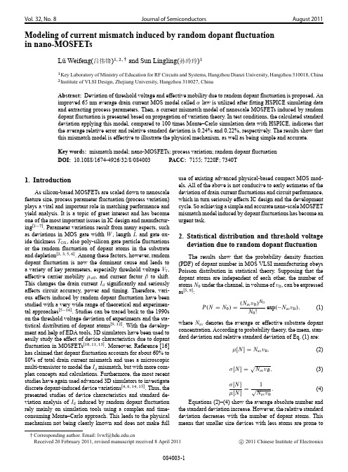
Vol.32,No.8Journal of Semiconductors August2011 Modeling of current mismatch induced by random dopant fluctuationin nano-MOSFETsLüWeifeng(吕伟锋)1;2; and Sun Lingling(孙玲玲)11Key Laboratory of Ministry of Education for RF Circuits and Systems,Hangzhou Dianzi University,Hangzhou310018,China2Institute of VLSI Design,Zhejiang University,Hangzhou310027,ChinaAbstract:Deviation of threshold voltage and effective mobility due to random dopant fluctuation is proposed.Animproved65nm average drain current MOS model called˛law is utilized after fitting HSPICE simulating dataand extracting process parameters.Then,a current mismatch model of nanoscale MOSFETs induced by randomdopant fluctuation is presented based on propagation of variation theory.In test conditions,the calculated standarddeviation applying this model,compared to100times Monte–Carlo simulation data with HSPICE,indicates thatthe average relative error and relative standard deviation is0.24%and0.22%,respectively.The results show thatthis mismatch model is effective to illustrate the physical mechanism,as well as being simple and accurate.Key words:mismatch model;nano-MOSFETs;process variation;random dopant fluctuationDOI:10.1088/1674-4926/32/8/084003PACC:7155;7220F;7340T1.IntroductionAs silicon-based MOSFETs are scaled down to nanoscale feature size,process parameter fluctuation(process variation) plays a vital and important role in matching performance and yield analysis.It is a topic of great interest and has become one of the most important issues in IC design and manufactur-ingŒ1 7 .Parameter variations result from many aspects,such as deviations in MOS gate width W,length L and gate ox-ide thickness T OX,also poly-silicon gate particle fluctuations or the random fluctuation of dopant atoms in the substrate and depletionŒ2;3;5;6 .Among these factors,however,random dopant fluctuation is now the dominant cause and leads to a variety of key parameters,especially threshold voltage V T, effective carrier mobility eff,and current factorˇto shift. This changes the drain current I d significantly and seriously affects circuit accuracy,power and timing.Therefore,vari-ous effects induced by random dopant fluctuation have been studied with a very wide range of theoretical and experimen-tal approachesŒ5 16 .Studies can be traced back to the1990s on the threshold voltage deviation of experiments and the sta-tistical distribution of dopant atomsŒ9;12 .With the develop-ment and help of EDA tools,3D simulators have been used to easily study the effect of device characteristics due to dopant fluctuation in MOSFETsŒ10;11;13 .Moreover,Reference[16] has claimed that dopant fluctuation accounts for about60%to 80%of total drain current mismatch and uses a microscopic multi-transistor to model the I d mismatch,but with more com-plex concepts and calculations.Furthermore,the most recent studies have again used advanced3D simulators to investigate discrete dopant-induced device variationsŒ4;6;14;15 .Thus,the presented studies of device characteristics and standard de-viation analysis of I d induced by random dopant fluctuation rely mainly on simulation tools using a complex and time-consuming Monte–Carlo approach.This leads to the physical mechanism not being clearly known and does not make full use of existing advanced physical-based compact MOS mod-els.All of the above is not conducive to early estimates of the deviation of drain current fluctuations and circuit performance, which in turn seriously effects IC design and the development cycle.So achieving a simple and accurate nano-scale MOSFET mismatch model induced by dopant fluctuations has become an urgent task.2.Statistical distribution and threshold voltagedeviation due to random dopant fluctuationThe results show that the probability density function (PDF)of dopant number in MOS VLSI manufacturing obeys Poisson distribution in statistical theory.Supposing that the dopant atoms are independent of each other,the number of atoms N0under the channel,in volume of v B,can be expressed asŒ5;9 :P.N D N0/D.N av v B/N0N0Šexp. N av v B/;(1)where N av denotes the average or effective substrate dopant concentration.According to probability theory,the mean,stan-dard deviation and relative standard deviation of Eq.(1)are:ŒN D N av v B;(2)ŒN D p N av v B;(3)ŒNŒN D1p Navv B:(4) Equations(2)–(4)show the average absolute number and the standard deviation increase.However,the relative standard deviation decreases with the number of dopant atoms.This means that smaller size devices with less atoms are prone toCorresponding author.Email:lvwf@Received20February2011,revised manuscript received8April2011c 2011Chinese Institute of Electronicslarger deviations due to a small amount of dopant atom fluctu-ation,which means that parameter variations caused by random dopant fluctuations in nano-MOSFET devices must be consid-ered.The volume v B in Eqs.(1)–(4)is defined as the multipli-cation of the depletion thickness and the channel area:v B D W eff L eff x d;(5) where W eff and L eff are effective channel width and length,and x d is the depletion layer thickness:x d D s4"0"si j˚F jqN av;(6)where"0is the dielectric constant,and"si is the relative dielec-tric constant of silicon.q denotes the electronic charge and˚F is the Fermi potential:˚F D kT q ln N av ni;(7) where n i is the intrinsic silicon carrier concentration and n i D 1.256 1016m 3when T D298K.An estimation of the relative deviation under various dopant atoms can be given by the above expressions.For a65nm MOS device process, (N)/ (N)D9.98%is the basis of circuit simulation when W eff D60nm,L eff D29.5nm and N av D2.54 1018cm 3.Existing approaches such as our theoretical analysis,ex-perimental study and simulation show that the threshold volt-age deviation induced by random dopant fluctuation can be simply expressed as below..V T/D q2sN av x dW eff L effT ox"ox:(8)If the substrate doping is uniform,the N av is almost a con-stant,and if the doping is non-uniform with distribution of dop-ing profile N a.x/,then N av can be expressed as an integrated equation(9),below:N av D3Z x D x dx D0N a.x/x dÂ1xx dÃ2d x:(9)3.Effects on effective mobility due to dopantatom fluctuationThe value of current factorˇdirectly affects the drain cur-rent,while effective mobility eff is one of factors inˇ.There-fore,effective mobility must be considered in a current mis-match model.However,theoretical analysis and experimental studies have shown that eff changes with the horizontal and vertical electrical field.BSIM4.6.1establishes the relationship between the lateral effective field E eff(i.e.the relationship be-tween the V gs and V T/and low field mobility 0:lf D 01C.E eff=E0/;(10) where is a constant related to mobility degradation andE eff D Q B C Q n=2"0"si V GS C V T6TOXE;(11)where TOXE,Q B and Q n are the electrical equivalent gateoxide thickness,depletion charge and channel charge respec-tively,which obviously indicates that both latter parametershave a direct relationship with the dopant atoms.Since calcu-lating lf based on Eqs.(10)and(11)is inconvenient,a uni-versal approximate relationship in Ref.[18]is given as:lf D32500E 13eff:(12)Also the vertical electric field V ds or velocity saturationmust be considered because the gate length is very short in nanofeature sizes,then:eff D lf1Clf j"L jv satD lf1Clf V dsL eff v sat;(13)where v sat is the saturation velocity of the carrier in a chan-nel and given as12.43 104m/s in a65nm SPICE model.Itshould be noted that eff is equivalent and changes from sourceto drain in an MOSFET.Difrenza et al.has found the relation-ship between the standard deviation eff and V T in studies ofˇD eff C ox W eff/L eff mismatchŒ17 :. eff/eff D eff˛d C ox .V T/;(14)where˛d is the Coulomb scattering coefficient.4.Current mismatch model4.1.Theoretical basisMismatch models of current in MOSFETs are mostly fromthe propagation of variance relationship(POV)based on theTaylor series.The relative standard deviation isŒ1;2;19 :.I d/I d D"XiÂ@I d@p iÃ2 2.p i/p2i#12;(15)where p i, 2.p i/denotes the i th electrical or process para-meter and its variance,respectively.According to statisticaltheory,all p i should be independent of each other,otherwise,the correlation coefficient should be added.It can be seenfrom Eq.(15)that the standard deviation of I d can be calcu-lated as long as an analytical expression is obtained where theparameters are associated with random doping.However,thewidely used BSIM4model for nano-scale MOSFETs is diffi-cult to use because it takes account for various physical effectsand includes a lot of correlation factors,where the redundancyand correlation between parameters exist,leading it being largeand complicated.Thus,applications of POV to analyze currentmismatch in nano-MOSFETs induced by random doping havenot yet seen and reported based on the BSIM4model.4.2.An improved ALPHA law modelALPHA(˛/law is a widely used submicron MOSFETmodel.A simple improved65nm˛law called the averagedrain current modelŒ1;20 is in Eq.(16),where C on D eff C ox,index˛p is between1–2, is the channel length modulationFig.1.˛law with fitted simulation data.factor and V DO is a matching constant.When V ds is the satura-tion voltage,V DO D V ds/(1C V ds/.For determining the para-meters ofˇ,V T,˛p, and V DO and demonstrating its valid-ity and reliability,it should be fitted by the current data under different V gs,V ds using HSPICE simulation with the BSIM4 (SPICE LEVEL54)65nm process modelŒ20 .I davg D 8ˆˆ<ˆˆ:C onWLV gs V T ˛p.1C V ds/ C onWLV gs V T ˛p V ds=V DOD (ˇ V gs V T ˛p.1C V ds/;saturation;ˇ V gs V T ˛p V ds=V DO;linear:(16)Researchers have pointed out that is not same under dif-ferent V gs and can be fitted by the quadratic modelŒ20 .In thisstudy,the model is depicted in Fig.1at V gs D1V,0.8V,0.6 V and0.4V,respectively,which shows that this model is suit-able except for individuals at the junction of saturation and thelinear region or V ds 0V.For example of V gs D1V,data of a total of46have been chosen to fit from V ds D0V to1.1 V every0.025V a total of33data in saturation(0.3–1.1V) and13in the linear region(0–0.3V),respectively.The inter-ested parameters V T D0.369V,˛p D1.10, D0.333V 1, V DO D0.25V,are extracted.It must be noted that the value ofˇchanges with V gs and V ds are mainly due to the effective mobility eff changes;in test conditionsˇis about7 10 5 A/V2.Statistical results show that the average relative error in saturation(plus and minus offset exist)is–0.011%,maximum 4.81%,minimum0.04%,and the average standard deviation is 1.26%,which is better than Ref.[1].It is slightly worse in the linear region for the average relative error of17.1%,standard deviation of33.4%,which is still close to the experimental re-sults in Ref.[1].Therefore,the˛law is suitable for nano-scale processes and better in analog applications,although analog circuits usually work in the saturation.4.3.Mismatch modelIn Eq.(16),the parametersˇand V T change with dopant fluctuations and are regarded as a certain correlation.The main reason is T OX,as some research papers have reported.Nevertheless,theoretical analysis shows that the para-meters eff,C ox,W eff and L eff are mutually independent of ˇŒ16;17;19 ,so the relative variance ofˇis:2.ˇ/ˇ2D2. eff/2effC 2.C ox/C2ox C2.W eff/W2effC 2.L eff/L2eff:(17)Existing papers and this study have shown that dopant fluc-tuation is only closely associated with effŒ17 ,soˇmismatch due to random dopant can be expressed as:2.ˇ/ˇD2. eff/eff:(18)Now the POV relationship based current mismatch,tak-ing into account the correlation between parameters induced by random dopant fluctuation,can be expressed as:2.I d/I2dD 2.ˇ/ˇ2C˛2p2.V T/V gs V T 2C2 .ˇ/ˇ˛p .V T/V gs V TD 2. eff/2effC˛2p2.V T/V gs V T 2C2 . eff/eff˛p .V T/V gs V T;(19) where is the correlation coefficient betweenˇand V T.This mismatch model is much simpler than many others because it has less parameters and does not have complicated ma-trix equations.However,the correlation between parameters is considered,so accuracy can be improved.Research has shown that is negative and relatively small,generally about0.1Œ21 , so–0.1is used in the model.Then Equation(19)together with Eq.(14)is:2.I d/IdDÄ. eff˛d C ox/2C˛2pV gs V TC2 eff˛d C ox˛pV gs V T/2.V T/:(20) 5.Simulation data and resultsFor studying the deviation of I d from random dopant ef-fects,a MOSFET circuit realizing V ds–I d characteristics is de-signed with BSIM4(SPICE LEVEL54)65nm model.100 Monte–Carlo simulations are run with random dopant varia-tions in accordance with Eq.(4)at a concentration of impurities N dep D N sub D N av D2.54 1018cm 3to obtain the curves and output data.Figure2obtained in V gs D V ds D1V shows that the drain current varies significantly with random dopant fluctuations.The maximum(Max),minimum(Min),average (Mean),absolute standard deviation( /and relative standard deviation( /Mean)of I d calculated in various another V ds are shown in Table1,where the theoretical analysis of( /Mean)is based on Eq.(20).It is clear that the theoretical and simulationTable1.Statistical data of current mismatch induced by random dopant fluctuation.V ds(V) 1.1 1.00.90.80.70.60.50.40.3 Max( A)63.55262.23460.89759.52858.10356.57254.80052.31447.369 Min( A)51.86950.89549.91048.90447.86446.76545.54544.01541.376 Mean( A)57.62456.49955.35954.19352.98451.69650.23548.29844.631 ( A) 2.601 2.526 2.450 2.371 2.287 2.192 2.071 1.859 1.335 /Mean Simulation 4.51 4.47 4.43 4.37 4.32 4.24 4.12 3.85 3.99 (%)Theoretical 4.25 4.25 4.25 4.24 4.25 4.25 4.25 4.27 4.27Fig.2.Monte–Carlo simulation shows current variation.Fig.3.Mismatch curves in different V ds.data are both close to about4%in test conditions.In addition, the comparison of /Mean between the theoretical and simu-lated data shows that average relative error(plus or minus off-set exist)and relative standard deviation is0.24%and0.22%, respectively.Curves of the mismatch model with V gs at differ-ent V ds are depicted in Fig.3,indicating that the mismatch is sensitive to V gs but not to V ds.Therefore,V ds is neglected as a more simple form of mismatch model is usually accepted.It should be pointed out that the above data are from an effective width and length ratio of60nm/29.5nm.However,the mis-match model is accurate for different width and length ratios, such as590nm/29.5nm in the simulation test.6.ConclusionsThis paper has studied the physical mechanisms and de-viations of V T and eff associated with MOSFET current mismatch induced by random doping fluctuation.A nano-MOSFET current mismatch model is presented through apply-ing an average drain current model called the improved˛law model.The model can estimate and predict the performance of MOS devices and circuits in the early stages of circuit design. Compared to HSPICE data in100Monte–Carlo simulations of BSIM465nm process,its average relative error and rela-tive standard deviation is0.24%and0.22%,respectively,in test conditions.Consequently,the proposed mismatch model is simple,effective and also accurate.References[1]Wang V,Agarwal K,Nassif S R,et al.A simplified design modelfor random process variability.IEEE Trans Semicond Manuf, 2009,22(21):12[2]Cao Y U,Clark L T.Mapping statistical process variations to-ward circuit performance variability:an analytical modeling ap-proach.IEEE Trans Computer-Aided Design of Integrated Cir-cuits and Systems,2007,26(10):1866[3]Saxena S,Hess C,Karbasi H,et al.Variation in transistor perfor-mance and leakage in nanometer-scale technologies.IEEE Trans Electron Devices,2008,55(1):134[4]Han M H,Li Y,Hwang C H.The impact of high-frequency char-acteristics induced by intrinsic parameter fluctuations in nano-MOSFET device and circuit.Microelectron Reliab,2010,50: 657[5]Srivastava A,Sylvester D,Blaauw D.Statistical analysis and op-timization for VLSI:timing and power.Beijing:Science Press, 2007[6]Li Y,Hwang C H,Li T Y.Random-dopant-induced variability inNano-CMOS devices and digital circuits.IEEE Trans Electron Devices,2008,56(8):1588[7]Borkar S.Designing reliable systems from unrealiable compo-nents:the challenges of transistor variability and degradation.IEEE Micro,2005,25(6):10[8]Mahmoodi H,Mukhopadhyay S,Roy K.Estimation of de-lay variations due to random-dopant fluctuations in nanoscale CMOS circuits.IEEE J Solid-State Circuits,2005,40(9):1787 [9]Mikolajick T,Haublein V,Ryssel H.The effect of random dopantfluctuations on the minimum channel length of short-channel MOS transistors.Appl Phys A:Mater Sci Processing,1997,64: 555[10]Asenov A,Slavcheva G,Brown A R,et al.Increase in the randomdopant induced threshold fluctuations and lowering in sub-100 nm MOSFETs due to quantum effects:a3-D density-gradient simulation study.IEEE Trans Electron Devices,2001,48(4):722 [11]Roy G,Brown A R,Adamu-Lema F,et al.Simulation study of in-dividual and combined sources of intrinsic parameter fluctuations in conventional nano-MOSFETs.IEEE Trans Electron Devices, 2006,53(12):3063[12]Mizuno T,Okamura J,Toriumi A.Experimental study of thresh-old voltage fluctuation due to statistical variation of channel dopant number in MOSFET’s.IEEE Trans Electron Devices, 1994,41(11):2216[13]Sano N,Tomizawa M.Random dopant model for three dimen-sional drift–diffusion simulations in metal–oxide–semiconductor field-effect-transistors.Appl Phys Lett,2001,79(14):2267 [14]Li Y,Yu S M,Hwang J R,et al.Discrete dopant fluctuated20nm/15nm-gate planar CMOS.IEEE Trans Electron Devices, 2008,55(6):1449[15]Li Y,Hwang C H,Huang H rge-scale atomistic approachto discrete-dopant-induced characteristic fluctuations in silicon nanowire transistors.Phys Status Solidi A,2008,205(6):1505 [16]Yang H,Macary V,Huber J L,et al.Current mismatch due to localdopant fluctuations in MOSFET channel.IEEE Trans Electron Devices,2003,50(11):2248[17]Difrenza R,Llinares P,Ghibaudo G.A new model for the cur-rent factor mismatch in the MOS transistor.Solid-State Electron, 2003,47(7):1167[18]Anderson B L,Anderson R L.Fundamentals of semiconductordevices.Beijing:Tsinghua University Press,2008:390(in Chi-nese)[19]Drennan P G,McAndrew C C.Understanding MOSFET mis-match for analog design.IEEE J Solid-State Circuits,2003, 38(3):450[20]Luo Z Y,Zhong Y Q.Transistor-level delay simulation method-ology for VLSI analysis.Journal of Computer-Aided Design& Computer Graphics,2006,18(12):1855(in Chinese)[21]Gruenebaum U,Oehm J,Schumacher K.Mismatch modelingand simulation—a comprehensive approach.Analog Integrat Circuits Signal Process,2001,29(3):165。
剖析MOSFET物理结构工作原理及失效

剖析MOSFET物理结构工作原理及失效MOSFET(金属氧化物半导体场效应管)是一种常见的电子器件,用于控制和放大电流。
它由多个不同的区域组成,包括金属栅极、氧化物绝缘层和半导体材料。
MOSFET的物理结构包括一个P型或N型的半导体基底,上面覆盖着一个绝缘层,然后是一个金属栅极。
这个栅极可以通过施加电压来控制绝缘层下的电荷密度,从而控制电流的流动。
当栅极电压为零时,绝缘层下没有电荷,大部分的电流被阻断。
当栅极电压与基底之间施加一个正电压时,绝缘层下形成一个正电荷层,使得电流可以通过。
相反,当栅极电压与基底之间施加一个负电压时,绝缘层下形成一个负电荷层,也使得电流可以通过。
因此,通过控制栅极电压,可以控制MOSFET中的电流。
MOSFET的工作原理基于场效应,即栅极电场的作用。
当栅极电压改变时,栅极下的电场也会改变,从而改变绝缘层下的电荷密度。
这个电场的改变会影响绝缘层和半导体之间的电荷分布,进而影响电流的流动。
当栅极电压高于阈值电压时,MOSFET处于导通状态,电流可以通过。
当栅极电压低于阈值电压时,MOSFET处于截止状态,电流被阻断。
然而,MOSFET也存在一些可能的失效模式。
其中一个常见的失效是漏电流增加,即在截止状态下存在较大的漏电流。
这可能是由于绝缘层中存在缺陷或污染物导致的。
另一个常见的失效是击穿,即当栅极电压过高时,绝缘层会被击穿,导致电流突然增加,可能会损坏MOSFET。
还有一个失效是热失效,即由于过高的工作温度导致MOSFET中的电子迁移率降低,进而影响电流的流动。
此外,还有一些其他的失效模式,如电荷泵效应、硬件故障等。
总的来说,MOSFET是一种重要的电子器件,具有复杂的物理结构和工作原理。
了解其物理结构和工作原理,以及可能的失效模式,对于设计和维护电子系统都非常重要。
复旦大学半导体器件第八章MOSFET

• 解决的办法是:在设计结构上尽量减少寄生晶体管电流增益或采用SOI工 艺消除寄生晶体管。
• 按照以上的按比例缩小规则制作的器件:器件的工作速度提高倍、密度 增加2倍、功耗降低2倍、阈值电压的减小接近倍;而亚阈值电流基本 不变。与此同时由于寄生电容没有减少和互连电阻增加会使延迟时间增 加。
MOSFET 的二级效应
1o 非常数表面迁移率效应(表面散射、栅电场) ; 2o 漏端速度饱和效应;
CMOS闭锁效应
• 前面看到CMOS结构有寄生的NPNP结构。 • NPNP结构可以看作由PNP和NPN两个晶体管的复合结构。
P
P
N
N
N
P
P
P
N
N
• 从图中不难看出这是一个触发器,只要两个晶体管共基极电流增益之和 等于1,该结构就处于导通状态。
• 当上端接正时中间的PN结是反向的,而上端接负时上下两个PN结都是反 向的,因此可以认为它们处于截至状态。这时电流很小,电流增益也很 小,不会导通。
MOSFET 的击穿特性
漏-衬底pn结雪崩击穿
1. 源漏击穿 沟道雪崩击穿
漏源势垒穿通
饱和区
2. 栅击穿
线性区
1. 源漏击穿
(1) 漏-衬底 pn 结雪崩击穿 ( BVDS )
VGS
n+ p-Si
VDS n+
BVDS
sEc2
2qNA
NA BVDS
- 1、下载文档前请自行甄别文档内容的完整性,平台不提供额外的编辑、内容补充、找答案等附加服务。
- 2、"仅部分预览"的文档,不可在线预览部分如存在完整性等问题,可反馈申请退款(可完整预览的文档不适用该条件!)。
- 3、如文档侵犯您的权益,请联系客服反馈,我们会尽快为您处理(人工客服工作时间:9:00-18:30)。
J l 0 1 uy 2 1
一
个 简 单 的 6 m 5 a MOS E F T失 配 模 型
吕 , 伟锋 孙玲玲”
1( 州 电子 科 技 大 学 教 育部 射 频 电路 与 系 统 重点 实 验 室 杭
杭 州 3 0 1 ) 10 8
z( 江 大学 超 大 规 模 集 成 电 路设 计 研 究 所 杭 州 3 0 2 ) 浙 1 0 7
(v @ hd . d . n) 1wi u eu c
摘
要 : )F T 的精 确 匹 配对 模 拟 和混 合 集 成 电 路 的 性 能 至 关 重 要 , 着 器 件 特 征 尺 寸减 小 至 纳米 , MOS E M( E S 随 将 FT
失配 模 型 进 行 改 良以 适 应 新 工 艺 显 得 十 分 迫 切 . 中 应 用 改 进 的 AI HA 律 平 均 漏 电 流 模 型 拟 合 6 m 器 件 的 文 P 5 n
r ltv v r ge e r r a t nd r v a i s 1 7 ea i e a e a r o nd s a a d de i ton i . O
a d 8. 6 r s e tv l n 2 e p c i e y,t n a smpl id 6 m he i i e 5n f
关键词 : 配 ; 失 MOS模 型 ; 艺 波 动 ; 米 器 件 i id 6 S m lfe am OS 5 M FET im a c o e M s th M d l
Lu W ef ng ’ a d Su n i g ie n n Li gln
p ro m a c fa l a m i e I . T h s p pe iie a i p ov d a ph — o e —a t i 6 n e f r n e o naog nd x d Cs i a r utlz s n m r e l a p w rl w o ft 5 m M o S m o ld t n xta tr l t d pr c s ar m e e s I o pa io ih BSI 4 de a a a d e r c e a e o e s p a t r. n c m rs n w t M m o e a a, t d ld t he
( yL b r tr f Mi i r f E u a in i F C ru t a d S se ,Ha g h uDi n i n v r i Ke a o a oy o n s y o d c to n R ic i n y tms t s n z o a z i e s y,Ha g h u 3 0 1 ) U t n z o 1 0 8 。 ( nttt . ID sg ,Z e in n v ri I s u e f W S e i n h ja g U i est i o y,Ha g h u 3 0 2 ) n z o 1 0 7
A b ta t M im a c m o l t ft e sr c : s th des o i n w p o e s r c s ha e e om e a tc a l ur e wih v b c p r iulr y g nt t M O S de i e vc s
f a ur ie a e s a e o n n e t e sz r c ld t a ome e c l e t h mpo t n e o OSFET x c t h f r t i l t r s a e du o t e i r a c fM e a tma c o he fna
第 2 卷第 7 3 期 21 0 1年 7月
计 算 机 辅 助 设 计 与 图形 学 学 报
J u n l fCo u e — d d De in & Co u e a hc o r a mp t rAie sg o mp t rGr p is
Vo1 3 N O .2 .7
M OS FET im a c od lf rc lultn t n r e i to Spr s n e s d o hi m pr v d m o e m s th m e o a c a i g s a da d d v a in i e e t d ba e n t si o e dl a d POV e p e so n x r s i n. T h e pe i e a r s ls ho e x rm nt l e u t s w t t he e a i e v r g e r r n s a da d ha t r l tv a e a e r o a d t n r d v a in i 6 e i to S7. 9 a d1 . 9 n 0 4 r s c ie y be w e n t i im a c o e n on e Ca l i u a i e pe tv l t e h s m s t h m d la d M t - ro sm l ton
HS I E仿 真 数 据 , 提 取 了 相 关 工 艺 参 数 , 模 型 与 B I PC 并 该 S M4模 型 数 据 相 比 平 均 相 对 误 差 为 1 7 , 对 标 准 差 .0 相 8 2 ; 利用 该 模 型并 结 合 偏 差 传 递 公 式 实 现 了 一个 简单 的 6 n 工艺 MOS器 件 电 流 失 配标 准差 计 算 模 型 . 验 .6 再 5m 实 结 果 显 示 , 模 型 与 HS I E蒙 特一 罗 仿 真 数 据 相 比平 均 相 对 误 差 为 7 6 , 对 标 准 差 为 l . 9 . 表 明 文 中 该 PC 卡 .9 相 O 4 这 模 型 简 单 、 效 , 能 保证 精 度 . 有 又