
智能红外传感器AS612
8
PIR
A S 6 12
南阳森霸光电股份有限公司
敏感元分类 1:A类 2:B类
电源电压 1: 外部提供3V直流电源 2: 内置3V稳压二极管
引脚数 3:3pin 4:4pin 6:6pin
窗口大小 S:3*4mm M:4.2*5.2mm L:3.8*5mm
性能参数
IC 型号
A:IC1 B:IC2 D:IC3 H:IC4 Z:IC5
备注
2.工作条件 (T=25°C, Vdd=3V,除另有规定外)
电源电压 工作电流
参量
符号 最小值 典型值 最大值 单位
备注
VDD
2.7
3
3.3
V
IDD
12
15
20
μA
灵敏度阀值 输出REL 输出低电流 输出高电流 REL的低电平输出锁定时间 REL的高电平输出延时时间
VSENS
120
IOL
10
IOH
大于这个电平就记为一个有效的脉冲信号,低于它则认为是无效的信号。如果把这个 SENS 引脚直接接地,那么探头 内部就认为是最低的门槛电压,这样就认为探头具有最高的灵敏度。这种方式可以把探头自身的噪声进行有效的过滤, 防止误触发。如果该引脚的电压大于 VDD/4,则门槛电压是最高的,探头的灵敏度也最低。该引脚电压和内部阈值电 平的关系如下图:
R6
R8
R10
0R
C5
100 K C6
75K
C7
10u F/16V
10u F/16V
10u F/16V
CD S GL 5528( 10K-2 0K)
R11 100 R
B
DS1
LA MP
LO UT
1
3
B
R4
ห้องสมุดไป่ตู้
1
10K
Q1 2N 7002
2
A
注:本电路为 AS612 数字智能热释电红外传感器的参考电路
A
外观尺寸图
Step
ONTIME 中心值电压 (V)
(VDD*(Step*2)+3)/128
0
3/128 或更低
1
(VDD*2+3)/128
2
(VDD*4+3)/128
3
(VDD*6+3)/128
4
(VDD*8+3)/128
5
(VDD*10+3)/128
6
(VDD*12+3)/128
7
(VDD*14+3)/128
南阳森霸光电股份有限公司
数字智能热释电红外传感器 AS612
产品概述
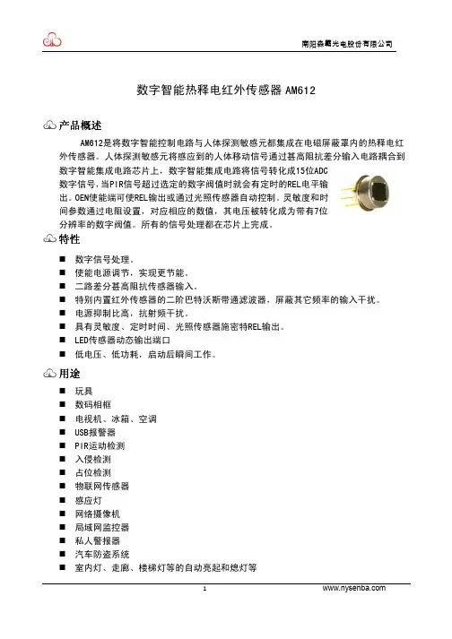
AS612是将数字智能控制电路与人体探测敏感元都集成在电磁屏蔽罩内的热释电红 外传感器。人体探测敏感元将感应到的人体移动信号通过甚高阻抗差分输入电路耦合到 数字智能集成电路芯片上,数字智能集成电路将信号转化成15位ADC 数字信号,当PIR信号超过选定的数字阀值时就会有定时的REL电平输 出。OEN使能端可使REL输出或通过光照传感器自动控制。灵敏度和时 间参数通过电阻设置,对应相应的数值,其电压被转化成为带有7位 分辨率的数字阀值。所有的信号处理都在芯片上完成。
1.最大额定值
任何超过下面表格中参数的电气应力都可能造成器件的永久性损坏。在这些最大额定条件下工作可能会对器件
的可靠性造成影响。
参量 电源电压 工作温度 任何引脚极限 存储温度
符号 VDD TST Into TST
最小值 -0.3 -20 -100 -40
最大值 3.6 85 100 125
单位 V ℃ mA ℃
8
(VDD*16+3)/128
9
(VDD*18+3)/128
10
(VDD*20+3)/128
11
(VDD*22+3)/128
12
(VDD*24+3)/128
13
(VDD*26+3)/128
14
(VDD*28+3)/128
15
(VDD*30+3)/128 或更高
ONTIME(s)
(典型值) 2.3 4.7 7 9.4 18.7 37 56 1min 15 sec 2min 30 sec 5min 7min 29 sec 9min59 sec 19min 58 sec 39min 56sec 59min25 sec 1hour20min
VS S
VD D
3.3V
12V
C
LIN
U1
C
6
2
1
5
3
4
1
VO UT
3
2
R1
1M NIN
1
C1
0.6 8uF/40 0V
NO UT 1
D1 ZM M12
R2 150 R/1W
1
2
D2 M7
+ CE 1
2
220 uF/50 V
VIN
1
GN D
1
HT 7533
+ CE 2 100 uF/25 V C2 104
5m 50°
12m Y
侧视图
注:1.X-Y 截面图表示检测区域。 2.检测区域内有温度差的检测对象横切后可进行检测。
6
1
2
D
典型应用电路
3
南阳森霸光电股份有限4 公司
D
3 1
2
5
2
D3
K1
U2
1N 4148
612
4
1
R5
R7
R9
1M
1M
1M
TOINMEE
SEN S
OU T
2.检测区域扩大的情况下 周围环境温度和人体的温度差较大的情况下(约 20℃以上),即使在指定的检测范围以
外,有时也存在广阔性检测区域。 3.关于其他使用
1)窗口上有污渍附着时,将会影响检测性能,因此敬请注意。 2)透镜是由柔弱材料(聚乙烯)制成的。在透镜上施加载重或者冲击后,将会因变形和 损伤引起动作不良和性能劣化,因此请避免上述情况的发生。 3)施加±200V 以上的静电时可能会造成破坏。因此,操作时请十分注意,避免直接用手 碰触端子等。 4)对导线进行焊接的情况下,手焊接时请在电烙铁温度为 350℃以下、3 秒以内进行焊接。 通过焊锡槽进行焊接时,可能会导致性能恶化,因此请避免。 5)请避免清洗本传感器。否则清洗液侵入透镜内部,可能造成性能恶化。 6)通过电缆配线使用时,为防止干扰所产生的影响,建议使用屏蔽线,并尽量缩短配线。
3
南阳森霸光电股份有限公司
智能探头报警触发时序图 4. REL 输出的 ON Time 时间
当探头检测到人体移动信号之后,会在 REL 引脚上输出一个高电平。该电平的持续时间由施加在 ONTIME 引脚 的电平来决定(见下表)。如果在 REL 高电平器件有多次触发信号产生,只要检测到新的触发信号,REL 的时间将 被复位,然后重新计时。
TOL
TOH
2.3
530
μV
mA VOL<1V
-10
mA VOH>(VDD-1V)
2.3
s 不可调
4793
s
2
输入SENS/ONTIME 电压输入范围 输入偏置电流 使能OEN 输入低电压
输入高电压
输入电流
振荡器和滤波器 低通滤波器截止频率 高通滤波器截止频率 芯片上的振荡器频率
电压值(V)
(VDD=3V) 0 0.07 0.117 0.164 0.21 0.257 0.304 0.351 0.398 0.445 0.492 0.539 0.585 0.632 0.679 3
ONTIME引脚分压电阻推荐值
(±1%精度)
上拉电阻
下拉电阻
不贴 1M 1M 1M 1M 1M 1M 1M 1M 1M 1M 1M 1M 1M 1M 0R
特性
数字信号处理。 使能电源调节,实现更节能。 二路差分甚高阻抗传感器输入。 特别内置红外传感器的二阶巴特沃斯带通滤波器,屏蔽其它频率的输入干扰。 电源抑制比高,抗射频干扰。 具有灵敏度、定时时间、光照传感器施密特REL输出。 LED传感器动态输出端口 低电压、低功耗,启动后瞬间工作。
样的信号,它会认为是接收到了第二个脉冲,一旦在 4 秒钟之内接收到 2 个脉冲以后,探头就会产生报警信号,同时 REL 引脚有高电平触发。另外,只要接收到的信号幅值超过触发阈值的 5 倍以上,那么,只需要一个脉冲就能触发 REL 的输出。下图为触发逻辑图示例。对于多次触发情况,输出 REL 的维持时间从最后一次有效脉冲开始计时。
用途
玩具 数码相框 电视机、冰箱、空调 USB报警器 PIR运动检测 入侵检测 占位检测 物联网传感器 感应灯 网络摄像机 局域网监控器 私人警报器 汽车防盗系统 室内灯、走廊、楼梯灯等的自动亮起和熄灯等
1
产品型号体系
0R 24K 39K 56K 75K 91K 110K 130K 150K 174K 200K 220K 240K 270K 294K 不贴
ONTIME引脚电压中心值对应的REL输出高电平持续时间
4
南阳森霸光电股份有限公司
5. 灵敏度/触发阈值 探头的触发阈值由施加在 SENS 引脚上的电平值来确定,该电平值决定了内部 PIR 信号的门槛电平和触发条件,
PIR信号门槛电压雨SENS引脚上电平的关系 6、OEN 引脚滞回电平
OEN 引脚滞回电平
5
窗口材料的透射光谱
南阳森霸光电股份有限公司
探测视角
12m
智能红外传感器AS612

智能红外传感器AS612智能红外传感器AS612范本:________简介:________智能红外传感器AS612是一款高性能的红外传感器,适用于各种智能安防系统和自动化控制系统。
它具有高精度、高可靠性和多种功能特性,能够实现精确的无线通信和远程监控。
1.产品规格1.1 外观尺寸:________ mm × mm × mm1.2 工作电压:________ V1.3 工作电流:________ mA1.4 探测范围:________ 米1.5 探测角度:________ 度1.6 信号输出:________数字信号1.7 通信接口:________无线1.8 防护等级:________IP652.主要特性2.1 高精度测量:________采用先进的红外技术,实现对目标物体的准确测量。
2.2 高可靠性:________具有稳定的性能指标和长寿命,适用于各种复杂环境。
2.3 多种功能特性:________支持远程监控、人体检测、温度测量等多种功能。
2.4 灵活性:________可根据用户需求进行定制配置,方便集成到不同的系统中。
2.5 易安装与维护:________采用标准接口和简单的安装步骤,操作简便。
3.使用说明3.1 安装方式:________将AS612固定在所需位置,确保传感器正面朝向待测物体。
3.2 上电:________连接合适的电源,确保工作电压符合规格要求。
3.3 参数配置:________通过无线通信接口,根据需要配置传感器的参数,包括探测范围、角度等。
3.4 功能调试:________通过远程监控或相关软件,对传感器的功能进行调试和测试。
3.5 维护保养:________定期清理灰尘和污垢,并检查连接线路是否正常。
4.警告与注意事项4.1 用户必须仔细阅读和理解本文档,并严格按照操作说明进行操作。
4.2 在使用过程中,应避免将AS612暴露在高温、潮湿等恶劣环境中。
智能红外传感器AS612[1]
![智能红外传感器AS612[1]](https://360docs-1393072327.cos.ap-beijing.myqcloud.com/f26dc584fc0a79563c1ec5da50e2524de518d0bc.webp)
智能红外传感器AS612智能红外传感器AS612智能红外传感器AS612是一种高性能的红外线(IR)探测器,采用先进的传感技术和智能算法,能够准确地检测和识别物体的移动。
AS612广泛应用于安防系统、智能家居、自动化控制等领域,提供可靠、精确、高效的移动检测解决方案。
特点与优势1. 高度灵敏:AS612采用先进的红外技术,能够高度敏感地检测到物体的移动,无论是静止的目标还是快速移动的物体。
2. 宽波动范围:AS612在工作频率范围内具有较大的探测角度,可以覆盖更广泛的区域,提供更全面的监测能力。
3. 低功耗设计:AS612采用低功耗设计,不仅可以减少能源消耗,延长电池使用寿命,还有助于减少对环境的影响。
4. 可靠性和稳定性:AS612具有出色的抗干扰能力,能够在多种复杂环境下稳定工作,减少误报和漏报的可能性。
5. 智能算法支持:AS612内置先进的智能算法,能够实现人体检测、烟雾检测、扰动检测等功能,提供更多应用场景的支持。
6. 易于安装和使用:AS612的设计紧凑而简洁,安装方便快捷。
用户只需按照说明书将传感器正确安装在需要监测的位置即可。
技术规格以下是AS612智能红外传感器的一些关键技术规格:- 工作电压:3V- 静态工作电流:≤50uA- 工作温度:-20°C至60°C- 探测距离:0-5m(可自定义调节)- 探测角度:120°- 输出电平:高电平(3V)/低电平(0V)- 输出方式:脉冲输出- 尺寸:25mm x 12mm x 10mm应用场景AS612智能红外传感器可以广泛应用于各种场景,包括但不限于以下几个方面:1. 安防系统AS612能够快速准确地检测到移动物体,可以应用于安防系统,实现入侵检测、区域监控等功能。
当AS612检测到有人或物体进入监控区域时,会触发报警系统,及时通知相关人员。
2. 智能家居AS612可以集成到智能家居系统中,用于检测居民的活动。
AS6122红外遥控器芯片

1. 编码方式............................................................................................................................................. 5
六. 功能说明................................................................................................................................................... 5
E_mail;rmcsales@
第 4 页 共 15 页
深圳市爱思科微电子有限公司 Shenzhen ASIC Micro-electronics Ltd.
AS6122
六. 功能说明
1. 编码方式
AS6122 所发射的一帧码含有一个引导码,16位的用户编码和8位的键数据码、键数据码的反码 也同时被传送。码型结构如下:
每个键输入端与电源负端VSS之间均接有下拉电阻。当有超过一个以上的按键(除非双重按键的 组合21#与22#键21#与23#键21#与24#键)同时按下时,码的发射输出将停止。
当一个键按下时先读取用户码和键数据码,22ms后遥控输出端(REM)启动输出,按键时间只有 超过22ms才能输出一帧码,超过108ms后才能输出第二帧码。
四. 结构框图
E_mail;rmcsales@
第 3 页 共 15 页
深圳市爱思科微电子有限公司 Shenzhen ASIC Micro-electronics Ltd.
HL6122
HL6122-多功能红外遥控发射电路概述HL6122电路是通用红外线遥控发射CMOS集成电路。
该电路由外部连接二极管与上拉电阻,并与内部ROM组合可产生多达65536种用户码。
电路的振荡频率由外接谐振器控制在400KHz~500KHz之内(通常在455KHz)。
本电路主要用于电视机、VCD、音响、功放、空调等家用电路的遥控发射器之中。
功能特点z低工作电压(V DD:2.0~3.3V)。
z低功耗(待机模式下I DD<1μA)。
z数据编码1.HL6121:32个单键输入和3个双键输入,利用SEL脚可扩展到64+6个功能键。
2.HL6122:64个单键输入和3个双键输入,利用SEL脚可扩展到128+6个功能键。
z可选择65536种用户码(外部二极管、上拉电阻与内部ROM组合)。
z封装形式:HL6121为SOP20,HL6122为SOP24。
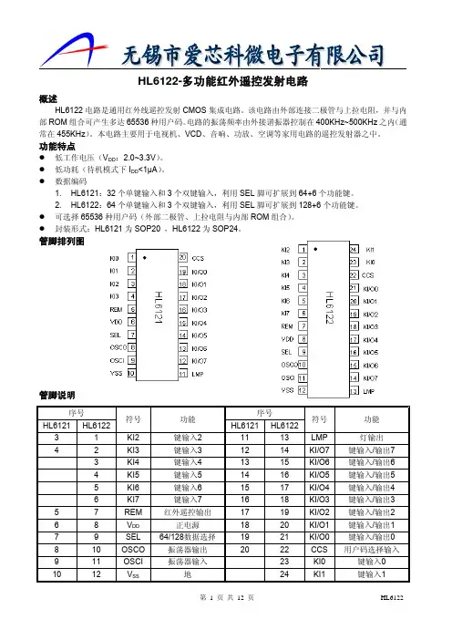
管脚排列图管脚说明序号符号功能序号符号功能HL6121HL6122HL6121HL612231KI2键输入21113LMP灯输出42KI3键输入31214KI/O7键输入/输出7 3KI4键输入41315KI/O6键输入/输出64KI5键输入51416KI/O5键输入/输出55KI6键输入61517KI/O4键输入/输出46KI7键输入71618KI/O3键输入/输出3 57REM红外遥控输出1719KI/O2键输入/输出2 68V DD正电源1820KI/O1键输入/输出1 79SEL64/128数据选择1921KI/O0键输入/输出0 810OSCO振荡器输出2022CCS用户码选择输入911OSCI振荡器输入23KI0键输入0 1012V SS地24KI1键输入1功能框图*:HL6121KI0~KI3HL6122KI0~KI7HL6121和HL6122功能比较功能说明1.引脚功能:(1)键输入管脚(HL6121为KI0~KI3,HL6122为KI0~KI7),键输入/输出管脚(KI/O0~KI/O7)在键输入管脚和V SS之间有一个下拉电阻。
热释电数字智能传感器 AM612_V1.4
Step
ONTIME 中心值电压 (V)
(VDD*(Step*2)+3)/128
0
3/128 或更低
1
(VDD*2+3)/128
2
(VDD*4+3)/128
3
(VDD*6+3)/128
4
(VDD*8+3)/128
5
(VDD*10+3)/128
6
(VDD*12+3)/128
7
(VDD*14+3)/128
R11 100R
B
DS1
LAMP
LO UT
1
3
B
R4
1
10K
Q1 2N7002
2
典型应用电路
A
A
1
2
3
4
南阳森霸光电股份有限公司
注意事项
1.AM612 是检测红外线变化的热释电红外传感器。检测人体以外的热源,或无热源温度变化 及移动的情况下,可能无法进行检测。需要注意以下一般事项。请务必通过实际使用状态确 认性能以及可靠性。
1
产品型号体系 ISB A
M6
12
南阳森霸光电股份有限公司
敏感元分类 1:A类 2:B类
电源电压 1: 外部提供3V直流电源 2: 内置3V稳压二极管
引脚数 3:3pin 4:4pin 6:6pin
窗口大小 S:3.8*5mm M:4.2*5.2mm L:4.9*4.9mm
最大值 3.6 85 100 125
单位 V ℃ mA ℃
备注
2.工作条件 (T=25°C, Vdd=3V,除另有规定外)
参量 电源电压 工作电流 灵敏度阀值
红外遥控解码原理(日本NEC的uPD6121G)

红外遥控解码原理(日本NEC的uPD6121G)这里我们以红外线遥控编码芯片为uPD6121G(或者是 HT622、7461等芯片)为例来说明用单片机实现红外遥控解码的详细过程。
红外线遥控是目前使用最广泛的一种通信和遥控手段。
由于红外线遥控装置具有体积小、功耗低、功能强、成本低等特点,因而,继彩电、录像机之后,在录音机、音响设备、空凋机以及玩具等其它小型电器装置上也纷纷采用红外线遥控。
工业设备中,在高压、辐射、有毒气体、粉尘等环境下,采用红外线遥控不仅完全可靠而且能有效地隔离电气干扰。
1 红外遥控系统通用红外遥控系统由发射和接收两大部分组成,应用编/解码专用集成电路芯片来进行控制操作,如图1所示。
发射部分包括键盘矩阵、编码调制、LED红外发送器;接收部分包括光、电转换放大器、解调、解码电路。
2 遥控发射器及其编码遥控发射器专用芯片很多,根据编码格式可以分成两大类,这里我们以运用比较广泛,解码比较容易的一类来加以说明,现以日本NEC的uPD6121G组成发射电路为例说明编码原理。
当发射器按键按下后,即有遥控码发出,所按的键不同遥控编码也不同。
这种遥控码具有以下特征:采用脉宽调制的串行码,以脉宽为0.565ms、间隔0.56ms、周期为1.125ms的组合表示二进制的“0”;以脉宽为0.565ms、间隔1.685ms、周期为2.25ms的组合表示二进制的“1”,其波形如图2所示。
上述“0”和“1”组成的32位二进制码经38kHz的载频进行二次调制以提高发射效率,达到降低电源功耗的目的。
然后再通过红外发射二极管产生红外线向空间发射,如图3所示。
UPD6121G产生的遥控编码是连续的32位二进制码组,其中前16位为用户识别码,能区别不同的电器设备,防止不同机种遥控码互相干扰。
该芯片的用户识别码固定为十六进制01H;后16位为8位操作码(功能码)及其反码。
UPD6121G最多额128种不同组合的编码。
遥控器在按键按下后,周期性地发出同一种32位二进制码,周期约为108ms。
低功耗太阳能无线红外传感器
直接输出数据信号进行处理,这样可以减轻单片机的工作负担。
图3 10P368解码IC电原理图 无线信号容易受到信道噪声的干扰,通常每个发射端信号数据 帧中加入同步头,触发一次发送多组同样的数据帧,接收端对同步 头进行监测,在同一时刻只要接收到1组则视为有效接收。
2.4 无线发射及接收模块 数据调制模块采用ASK方式,中心频率选择在433MHz和
热释红外传感器,其特点是将人体探测敏感元与信号差分放大电路集
成在电磁屏蔽罩内,内置15位数字AD转换电路,与预设阀值进行比
较后输出REL电平。与传统的红外传感器加外置模拟放大电路相比,
二阶巴特沃斯带通滤波器能够屏蔽其他频率信号干扰,抗射频能力
更强。配合菲尼尔透镜,直线探测距离可达到10米以上,角度达100
会被赋予一个ID,在组网开始时,通过与接收端间配对的方式加入
接收端。信号数据帧中加入ID号以便接收端进行解码。
EV1527可以用于发射端的编码地址预设,由于内码高达20位
元,因此可以有效降低批量产品编码的重复可能性。红外传感器只
需要发送接收到的人体动作信号,利用IC的按键输入端D0~D1中的
1位作为数据,编码输出的数据帧发送至无线模块DATA端进行发 射。关于EV1527的具体信号可参考芯片的详细资料[1]。
度。在某些应用场合只需要在夜间对人体移动进行探测,因此增加光
敏管作为环境照度的测试,在低于10Lux的时候无线模块打开进行
发送,而白天则予以关闭以节约蓄电池电能(见图2)。
2.3 编/解码电路
在多个无线传感器发射终端安装的情况下,接收端需要对接收
信号进行识别,以判断传送信号的传感器具体位置,因此每个终端
1.引言
2.太阳能无线红外传感器系统
AS7262/AS7263多通道光谱片上传感器艾迈斯半导体公司
A1 3 3 7和 A1 3 3 8器 件 _ 在 设 计 时 充 分 考 虑 了 主 动 安 令 的 应 要 求 ,包 括 用 户 可 控 制 的 片 上 逻 辑 内 建 自 测 试 ( L — B I S T)和 完 整 信 号 路 径 的诊 断 , 以便 让 客 户 确 定: 片 是 否 正常 运 行 。 这 两 款 器 件 都 支 持 低 R P M 模 式 和高 R P M 模 式 , 分 别 用 于低 速 和 高 速 应 用 。 高 R P M
准确 地控 制 光源 和 光 谱检 测功 能 。
精品推介 _ P r o d u c t E x p c r o S y s t e ms , L L C推 出两 款全 新 0 ~ 3 6 0 。
艾迈斯半导体宣布推 出全球首款高性价 比的多通道 光谱片上传感器解决方案,为消费和工业应用实现新 一
Al 3 3 7和 Al 3 3 8可 以提 供 两种 封 装 选 项: 集 成
芯片的 l 4引 脚 T S S OP封 姨 和 集 成 双 芯 片 2 4引 脚 T S S O P封 装 。 两 种 封 装 部 不 禽 铅 , 引线 框 采 用 1 0 0 % 需锡 电镀 。
电路 的电子快 门,这意味着设备设计 师可 以通过单芯片
代 光谱 分 析仪 开 辟 了道路 。 采用 4 . 5 X4 . 4 mm 小 型 阵 列 封 装 ,超 低 功 率 A S 7 2 6 2 可 见 光传 感 器 和 A S 7 2 6 3近 红 外传 感 器 均提 供 六 个 经 过 校 准 的 光 谱通 道 。极 具 竞争 力 的 价 格 优 势 ,使 这 款 新 的 多通 道 光 谱传 感 器 为消 费 产 品 及现 实 领 域各 种 应 用 的 测
AM612 datasheet智能红外传感器
3
3.3V
4 3 5
R1 NIN 1 1M C1 0.6 8uF/40 0V
VIN 1
+ CE 2 100 uF/25 V GN D
C2 104
1 2 6
ON EE TIM
SEN S
VD D VS S OU T
R5 1M
R7 1M
R9 1M
1
R2 150 R/1W
R6 0R
2 D2 M7
1
C5 10u F/16V
图 2(a1) ONTMIE 脚不接电容
4
南阳森霸光电股份有限公司
图 2(a2) ONTMIE 脚不接电容(a1 的局部放大)
图 2(b) ONTMIE 脚接 100pF 电容到地
图 2(c) ONTMIE 脚接 1nF 电容到地
5
南阳森霸光电股份有限公司
2.检测区域内有温度差的检测对象横切后可进行检测。
8
1
2
3
4
南阳森霸光电股份有限公司
D
典型应用电路
2 5 1
K1
U2 612
D3 1N 4148
4
3
R11 100 R Q1 2N 7002 4
LIN 1
12V
C
U1
2
VO UT D1 ZM M12 + CE 1 220 uF/50 V 2
输入高电压 输入电流
0.4Vdd -1
V V
μA
OEN电压高到低的阈值电平 OEN电压低到高的阈值电平
1 7 0.44 64
VSS<VIN<VDD
振荡器和滤波器 低通滤波器截止频率
高精度红外激光传感器产品目录说明书
Choose from the largest selection of laser sensors in the industry!NEWLong-distance transparent object detection Area retro-reflectivelasers2Product compositionLaser sensor featuresThe LV Series are digital laser sensors consisting of both a sensor head and an amplifier.Please note that the supported amplifier unit depends on the sensor head.• Compact size• Transparent object detection (available) • Zero datum function (available)• High-power• Waterproof (available)• 0.39"/1.18" 10 mm/30 mm area• Analog outputReflective/Retro-ReflectiveThrubeamLV -S SeriesLV -H SeriesLV -H SeriesVisible beam allows for easy installation Stable target detection from a remote location Small beam spot ensures high precisionSensor head LV-11SB LV-12SBAmplifierSensor head LV-21A LV-22A LV-20AAmplifierSensor head LV-51M LV-52AmplifierNEW NEW3Selecting a beam shapeMethod of detectionSpecific sensor headAmplifierSelect an LV Series laser sensorSelect an LV Series laser sensor according to these selection stepsSTEP 4SPECIFICATIONSDIMENSIONSEffective for wide detection ranges, such as when the target’s position varies as it passes through the beam.Small Beam SpotEffective for highly precise detection of minute targets.Area BeamThe shape of the laser beam emitted on the target forms a small spot.The shape of the laser beam emitted on the target forms a line.P.5Retro-ReflectiveP.4Product selection guideSelecting a beam shapeSelect a laser sensor head, either an area beam or small beam spot, according to the target that is to be detected.4LV-S63NEW NEW NEWMethod of detectionSelect either a reflective, retro-reflective, or thrubeam sensor based on the application.Area BeamReflectiveRetro-ReflectiveP.9LV-H100LV-H300LV-H110object detectionP.65Small Beam SpotRetro-ReflectiveLV-S71LV-S72LV-H62LV-H67LV-H62FLV-H35(H35F)P.12STEP 3STEP 4SPECIFICATIONSDIMENSIONSSelect an LV Series laser sensor6Area Beam Retro-ReflectiveArea LaserLV-S621.69"42.80.49"12.4All models support the P.R.O. function. The polarizing filter reduces direct reflected light from a mirrored-surface target.1. Numbers not enclosed in parentheses are the detecting distance for area spot. Numbers enclosed in parentheses are the detecting distance for small beam spot.2. Numbers not enclosed parentheses are the detecting distance when an accessory reflector is used. Numbers enclosed in parentheses are the detecting distancewhen OP-51428 (sold separately) is used.(Note) We recommend that, when LV-S62 is used for glass detection, the detecting distance be set to 3.3' (1 m) or less.0.91"231.82"46.20.49"12.40.91"When installing the rear mountingbracket (sold separately)Using all of the mounting brackets allows you toadjust the optical axis right, left, up, and down.Reversed mounting0.54"13.60.75"191.50"382.52"640.86"21.81.73"44NEWOP-84350When installing the rear mountingbracket (sold separately)OP-84349When installing the rear mountingbracket (sold separately)OP-84351 Stable detection is possible due to the wide beameven if the target's position varies.Use this switch to selectarea spot or small beam spot.AreaSmallBe sure to use the dedicated mounting brackets because optical axis adjustment is required.Side view shape andsmall sizeReflectorR-6L (accessory)Product featuresSelecting a specific sensor headSelect a sensor head tailored to your application.Reversed mountingReversed mountingNEW7The beam shining on a target is clearly visible.Reflector R-6 grey (accessory)Reflector R-6 grey (accessory)Options Long-Distance AreaWide AreaLong-Distance Transparent Object DetectionLV-S63LV-H64LV-H65Distance (inch mm)200 400 600 800 1000Detection distance – area width characteristics(typical example)Area width (inch mm)50 100 150 200 250 300t=0.03" 0.7 mm50 mmAt a distance of approx. 3.94" (100 mm) width is approx. 1.97" (50 mm).NEWReflected light levels are averaged by widening the acceptance surface (approx. 1.26"x 0.59" 32 x 15 mm). This provides stable transparent object detection.Easy optical axis adjustmentDetecting distance98.4'30 mReflectorR-9 (accessory)for LV-H64 and H65(Note) We recommend that, when LV-S62 is used for glass detection, the detecting distance be set to 11.5' (3.5 m) or less.Area width (inch mm)Distance (inch mm)NEWNEWSTEP 3STEP 4SPECIFICATIONSDIMENSIONSSTEP 2When the mounting bracket is attached (accessory)Detection distance – area width characteristics(typical example)When the mounting bracket is attached (accessory)When the mounting bracket is attached (accessory)Select an LV Series laser sensorNEWWhat sets the LV-S62/S63 apart from conventional sensors for transparent object detection?Area laserBeam ShapeArea beams are excellent for detecting targets with gaps.Small spotLarge light quantity variation if position shiftsArea beamSmall light quantity variation even if position shiftsUnlike small beam spots, area beams are less affected by vibrating targets or backgrounds.LV-S63 also spreads the spot’s depth 0.31" 8 mm x 0.47" 12 mm to provide more stability.High-frequency superimposition drive circuitLaser BeamThe amplifier cancels light quantity variation.The zero datum function always monitors the received light quantity when there is no transparent object and keeps the displayed value at 0 (light quantity variation cancellation). If a transparent object is input, the function displays the difference. This makes it very easy for the LV Series amplifier to stably detect transparent targets.Can stably detect vibrating/inclining transparent targetsDue to the characteristics of lasers, the slightest incline of a transparent target can cause light diffraction resulting in unstable detection. The newly-developed laser drivecircuit found in the LV-S62 and LV-S63 compensates for this phenomenon.World‘s first zero datum functionAmplifierWhereas most lasers use a single wavelength, the LV-S62/S63 uses high-frequency superimposition technology to take a wide range ofwavelengths. This has enabled the practical elimination of transparent quantity changes.LV-11SB/12SBAmplifier unitNEW(Patent pending)Reflector8STEP 3STEP 4SPECIFICATIONSDIMENSIONSSTEP 2Selecting a specific sensor headSelect a sensor head tailored to your application.Area Beam Reflective1.38"0.49"0.79"12.420350.49"1.36"1.04"CharacteristicsLV-H47LV-H47LV-H4220406080100Received light quality (digit)120140Characteristics of received light quantity and distance (typical example)Characteristics of detecting distance and area width (typical example)Distanceinch (mm)Distance inch (mm)Widthinch(mm)Width inch(mm)Product features Long DistanceDefinite ReflectiveLV-L02An area width can be selected.The area becomes thicker.When the mounting bracket Select an LV Series laser sensor9Distance inch (mm)Standard /High Power (0.39" (10 mm) wide)LV-B101(Mounted vertical)LV-B102(Mounted horizontal)LV-B301(Mounted vertical)LV-B302(Mounted horizontal)OFF: Ignores small targets.ON: Responds to targetswith complete lightinterruption(2 brackets to 1 set)(2 brackets to 1 set)1247.44142.52034.2122041.3Example using the LV-H110The sensitivity of the LV-H100 has been increased. The LV-H100detects only targets that completely interrupt light.Up/Down adjustment is possible Easy optical axis adjustmentvia visible beamYou can clearly see the beambecause a light diffuser sheet isinserted into the end of thereceiver. This makes opticalaxis adjustment extremelyeasy.Mounting brackets providebeam position adjustment.Two types of mounting bracketsare available: Brackets formounting vertically and bracketsfor mounting horizontally. Be sureto use the dedicated mountingbracket because optical axisadjustment is necessary.LV-H100/110Standard (1.18" (30 mm) wide)LV-H300When the mounting bracketis attached (accessory)When the mounting bracketis attached (accessory)When the mounting bracketis attached (accessory)When the mounting bracketis attached (accessory)1.63"0.47"0.79"0.79"0.47"1.35"1.67"120.47"0.47"1.87"1.61"411.61"Area Spot ThrubeamSelecting a specific sensor headSelect a sensor head tailored to your application.Product features10(2 brackets to 1 set)(2 brackets to 1 set)ApplicationEnvelope printing check Area retro-reflective (wide)Sheet break detection Shaft arrival checkWorkpiece not inserted properlyLV-H42LV-H47LV-H65LV-H64Area spotHigh-power area spot thrubeam Presence/Absence detection of target in bag High-power area spot thrubeamSeal number countingSelect an LV Series laser sensorSTEP 3STEP 4SPECIFICATIONSDIMENSIONSSTEP 2Area thrubeam (1.18" (30 mm) wide)Workpiece location detection Area thrubeam (0.39" (10 mm) wide)Cotton looseness/cut detectionABNGOKNGLV-H300LV-H100LV-H110LV-H110Selecting a specific sensor headSelect a sensor head tailored to your application.Small Beam Spot Retro-ReflectiveDifference from fiber sensorCharacteristics*All models support the P .R.O. function. The polarizing filter reduces direct reflected light from a mirrored-surface workpiece.46.915.83612.42318Characteristics of detecting distance and spot diameter (typical example)Characteristics of detecting distance and spot diameter (typical example)Spot diameter (inch mm)LV-S61Distance(feet m)0.91"0.71"0.49"1.42"12.40.49"361.42"0.62'1.85'1.05"0.02"0.04"0.06"0.08"0.10"0.12"0.14"0.16"20001500100050012345678Select an LV Series laser sensorSTEP 3STEP 4DIMENSIONSSTEP 2SmallLong Distance (up to 164' (50 m))Product features and mounting brackets* The detecting distance remains unchanged even if the reflective tape is used.P.29LV-S61LV-H67StandardLV-H62W aterproof: IP67LV-H62FP.32P.32P.33P.32–P.3351.2t=0.03"130GlassFluorine-contained rubberFluoroplastic (PFA)Fluoroplastic (PFA)When the mounting bracket is attached (accessory)When the mounting bracket is attached (accessory)Reflector (accessory)Reflector (option)When the mounting bracket is attached (accessory)When the mounting bracket is attached (accessory)2.02" 5.12"Small Beam Spot ReflectiveSelecting a specific sensor headSelect a sensor head tailored to your application.CharacteristicsCharacteristics of setting distance and spot diameter (typical example)Spot diameter (Mil µm)Distance (inch mm)Distance(inch mm)Characteristics of detecting distance and minimum spot diameter (typical example)Spot diameter(inch mm)LV-H32LV-H3725130.49"12.40.49"12.40.49" 12.40.41" 10.40.911.30" 0.87"1.42"1.85"0.62"15.81.05"26.61.36"34.51.04" 26.51.04" 26.51.26" 0.51"0.24"0.98"0.24"40030020010075655545859510535Select an LV Series laser sensorSTEP 3STEP 4DIMENSIONSSTEP 2 Small Small Side-ViewSmall Adjustable Distance Setting Adjustable Beam SpotCoaxial StructureWaterproof: IP67Ultra-small Beam Spot (1.97 Mil (50 μm))Also lockableAdjustments aresecured using thelens position lockfeature.With the coaxialstructure, the LV-H35 canreceive reflected lighteven from a small gap.LV-S41 (S41L)LV-H32LV-H35FLV-H37LV-S31MaterialAccessoryAdjustable by handSpot adjustment can be easily madeby turning the focus ring by hand.GlassFluorine-contained rubberFluoroplastic(PFA)Product features and mounting bracketsWhen the mountingWhen the mounting bracketis attached (accessory)When the mounting bracketWhen the mounting bracketis attached (accessory)When the mounting bracketis attached (accessory)When the mounting bracketis attached (accessory)The supplied magnifyingglass enables users to checkthe beam spot position.Small Beam Spot ThrubeamSelecting a specific sensor headSelect a sensor head tailored to your application.Each symmetrical mounting bracket (two sets)(2 brackets to 1 set)Product featuresSmall Beam SpotLV-S71Step DifferentiationLV-S721.19" 30.2M61.19" 30.2M6High-precision differentiationThe receiver side uses a slit with a width of 0.02" (0.6 mm), allowing high-precision differentiation.Easy optical axis adjustmentOptical axis adjustment is easy becausethe spot diameter is approx. 0.02" (0.6 mm) and19.69" (500 mm) ahead of the transmitter (large spot).Small type mounting bracket (option)OP-66869The optical axis can be adjusted from above.Side viewer attachment(option) LV-F1The optical axis can be adjusted from above.Operation indicatorBoth the transmitter and receiver are equipped with an operation indicator.Ultra-smallLV-S71 is the smallest red laser sensor in its class.TransmitterTransmitterReceiverReceiverWorld’s SmallestSelect an LV Series laser sensorDetection of the presence/absence of a part (spot welding)Glass detection Detection of work pieces remaining in the mold.Small beam spot thrubeam (small, M6)Floating cover detection Rack stop position detectionCounter inputSmall beam spot retro-reflective (long distance)Protrusion detectionSmall beam spot thrubeam (small, M6)De-burr checkingNGOKLV-H32LV-S41LLV-H35LV-S31LV-S61LV-S71LV-S71LV-H67Small beam spotApplicationSTEP 3STEP 4SPECIFICATIONSDIMENSIONSSTEP 2Usually* the first digit of the digital display will drift when there is no workpiece. The zero datum function* clears the display to 0, eliminating this drifting status. (Returning to the nominal display when light isPopular DSC functionUnique form dust coverEasily adjustable large Secure head connectionPart names and featuresThe LV-S Series, comes with the world’s first zero datum function.The LV-S Series comes with the DSC function.LV-S SeriesExpansion unitMain unit1.24" 78.6 3.09"* For external input, select "light emission stop", "tuning", "set value bank selection" or "received light quantity shift." Up to 16 expansion units can be installed to one main unit.The main unit comes with an amplifier mounting bracket.The expansion unit comes with an end unit.Connectable sensor headsSelecting an amplifierWhen using one amplifier, select the main unit. When using two or more amplifiers, select one main unit and one or more expansion units.LV-H SeriesReflective or Retro-ReflectiveSelect an LV Series laser sensorSTEP 3STEP 4SPECIFICATIONSDIMENSIONSSTEP 2Expansion unitMain unitExpansion unitMain unitThe main unit comes with an amplifier mounting bracket.The expansion unit comes with an end unit.The main unit comes with an amplifier mounting bracket.The expansion unit comes with an end unit.1.12" 65.82.59"0.79" 20Connectable sensor heads*1 The LV-20A is also available to support the zero line. (It does NOT have a cable for power or outputs).*2 external inputs on the expansion units can be used for calibration. However, laser emission stop input cannot be used on the expansion units. Up to seven additional expansion units can be installed for each main unit.1.12" 74.62.94"0.79" 20*1 Laser emission stop input on the main unit only.Up to seven additional expansion units can be installed for each main unit.1.12" 28.565.8 2.59"0.79" 20Main unitConnectable sensor heads(Note) Only the LV-H41 and LV-H51 can be used with the LV-11A amplifier.LV-H Series ThrubeamVisible light semiconductor laserLV-S626.6' 2 m 32.8' 10 m (16.4' 5 m)26.2' 8 m (11.5' 3.5 m)16.4' 5 m (6.6' 2 m)LV-S SeriesLV-S71LV-S729.84" 250 mm15.75" 400 mm* IEC60825-1 based classification is made according to FDA (CDRH) Laser Notice No. 50 Regulations.* The parentheses indicate the detecting distance when the small beam spot is used.* Contains a symmetrical mounting bracket (two in total).Visible light semiconductor laserLV-S71LV-S7219.69" 500 mm* Contains a symmetrical mounting bracket (two in total).Specifications21Laser emission stop input/External calibration input/Setting value bank selection input/Received light intensity shift inputLV-11SB/12SB2.LV-11SBP/12SBP2.1. The LV-11SB only2. Black: Control output 1, white: Control output 2* The LV-11SB only 1. The LV-11SBP only2. Black: Control output 1, white: Control output 2* The LV-11SBP onlyAmplifierHSP: 80 µs FINE: 250 µs TURBO: 500 µs SUPER: 2 ms ULTRA: 4 ms (LV-S62 and LV-S63 can ONLY be used with amplifiers ending with B or BP.)1. LV-S62 and LV-S63 can ONLY be used with amplifiers ending with B or BP.2. Numbers for the LV-S31 are four in standard mode and two in high-speed mode.3. To connect several units they must be mounted on a METAL DIN rail. Ensure that the output current is 20 mA max. With several units connected, the allowable ambient temperature range varies as follows:1 to2 units connected: 14 to 131ºF (-10 to +55ºC)3 to 10 units connected: 14 to 122ºF (-10 to +50ºC) 11 to 16 units connected: 14 to 113ºF (-10 to +45ºC)4. When more than 8 units connected, be sure to use supply voltage 24 VDC Ripple (P-P) 10% max.Output circuitInput circuitLV-S SeriesSPED 1: 500 µs SPED 2: 2ms SPED 3: 8 ms SPED 4: 32 msSTEP 3STEP 4SPECIFICATIONSDIMENSIONSSTEP 2Input/Output CircuitsSpecifications22Straight-Beam, Retro-ReflectiveVisible light semiconductor laser Wavelength: 650 nm 2.76" ±0.59"5.91" 150 mm Small Beam SpotInvisible light semiconductor laser Wavelength: 785 nm 9.84" 250 mm Visible light semiconductor laser Wavelength: 650 nm6.6' 65.6' 20m ⅡVisible light semiconductor laser Wavelength: 650 nm3.94" to 19.69" (3.94" to 27.56") 100 to 500 mm (100 to 700 mm) 3.94"(5.91") 100mm (150 mm)7.87" to 33.46" (11.81" to 39.37") 0.39" to 5.91" (0.39" to 9.84") Class ⅡVisible light semiconductor laser Wavelength: 650 nmLV-H Series23Expansion unit (1 line)FINE: 80 µs/ TURBO: 500 µs/ SUPER TURBO: 4 ms280 µs to 4.7 msFINE: 500 µs/ TURBO: 2 ms/SUPER TURBO: 8 msNPN (PNP) open-collector x 2 channels, 40 VDC (30 V) max., max. 100 mA, residual voltage (1.0 V max.)1. To connect several units they must be mounted on a METAL DIN rail. Ensure that the output current is 20 mA max. With several units connected, the allowable ambient temperature range varies as follows:2. When 2 to 5 expansion units are additionally installed: 14 to 122˚F (-10 to +50˚C ). When 6 or 7 expansion units are additionally installed: 14 to 113˚F (-10 to +45˚C ).LV-L01 Specifications (lens attachment for LV-H42) (Unit: inch mm)LV-L02 Specifications (lens attachment for LV-H47) (Unit: inch mm)Main unit Expansion unit (0 line)Main unitSTEP 3STEP 4SPECIFICATIONSDIMENSIONSSTEP 2LV-H SeriesSpecifications24LV-H SeriesThrubeam0.39" 10 mmVisible light semiconductor laser Wavelength: 650 nm* Use a dedicated mounting bracket to install the sensor.1. To connect several units they must be mounted on a METAL DIN rail. Ensure that the output current is 20 mA max. With several units connected, the allowable ambient temperature range varies as follows:When 2 to 5 expansion units are additionally installed: 14 to 122ºF (-10 to +50ºC ). When 6 or 7 expansion units are additionally installed: 14 to 113ºF (-10 to +45ºC ).SUPER 4 ms25LV-H / LV-S SeriesCAD DATA Download Service/cadDimensionsSTEP 3STEP 4SPECIFICATIONSDIMENSIONSSTEP 2Analog output circuit for monitoring Laser radiation interruption (main unit only)External calibration input* Orange (monitor output) only for LV-51M* Orange (monitor output) only for LV-51MPLV-21A/11A/51MLV-21AP/51MPLV-22A/52LV-22AP/52PLV-21AP/51MPLV-21A/11A/51M(LV-51M/51MP only)Input/Output Circuits3Unit: inch mmReflector R-6L (Specifications / Dimensions26LV-S SeriesOP-84350L-shaped mounting bracket for LV-S62 (Option)OP-84349Rear mounting bracket for the LV-S62 (Option)Mounting bracketattachedMounting bracketattached18.819.5130.90.9Material: Stainless steelt=0.06" t=1.5Accessory screwM3, P=0.5× 7.3…1pieceMaterial: Stainless steel56110.06" 1.5Material: Stainless steelt=0.06" t=1.5Accessory screwsM3, P=0.5× 5…1pieceMaterial: Stainless steelM3, P=0.5× 16.5…1pieceMaterial: Stainless steelM3, P=0.5× 18…2pieceMaterial: Stainless steelAccessory nutM3…1 pieceMaterial: Stainless steelUnit: inch mm27DimensionsLV-S SeriesCAD DATA Download Service/cadRear mounting bracket for LV-S63 (Accessory)Mounting bracket attachedMounting bracket OP-84351Side mounting bracket for LV-S62 (Option)Material: Stainless steel t=0.08" t=2.0Accessory screws M4, P=0.7× 30…3piece Material: Stainless steel Accessory nut M4…3 piece48.8 2.2 13 STEP 1STEP 3STEP 4SPECIFICATIONSDIMENSIONSSTEP 2Unit: inch mm28LV-S31Mounting bracket for LV-S41/LV-S41L (Accessory)Installed bracketon the LV-S41Installed bracket on the LV-S41LCenter of Distance setting*Accessory screwsM3, P=0.5× 0.59" 15 …2piece Material: Iron (nickel-plated)LV-S SeriesUnit: inch mmInstalled bracketon the LV-S41L4t=1.0Dimensions LV-S SeriesCAD DATA Download Service /cadSTEP 1STEP 3STEP 4SPECIFICATIONSDIMENSIONSSTEP 22930LV-S SeriesUnit: inch mmDimensionsLV-11SB/11SBPLV-12SB/12SBPMounting bracket attached (LV-11SB and LV-11SBP DIN rail accessory)End unit(included with LV-12SB/LV-12SBP)When several units are connected(13)LV-S SeriesCAD DATA Download Service /cadSTEP 1STEP 3STEP 4SPECIFICATIONSDIMENSIONSSTEP 266Unit: inch mm31LV-H Seriesmm1.58.617.232335Material: Stainless steel t=0.05" t=1.2Material: Stainless steel t=0.06" t=1.5DimensionsLV-H SeriesCAD DATA Download Service/cadSTEP 1STEP 3STEP 4SPECIFICATIONSDIMENSIONSSTEP 2Unit: inch mm345.9Slit (Black)Slit (Grey)When mounting LV-L02LV-H47Slit seal (included with LV-L02)5.4LV-H Series610.5Unit: inch mm359.53177.52 x ø0.07"DimensionsLV-H SeriesSTEP 1STEP 3STEP 4SPECIFICATIONS DIMENSIONSSTEP 2CAD DATA Download Service/cadUnit: inch mm363.5LV-20A14.5min.LV-22A /22APEnd unit(included with LV-22A/22AP )When several units are connected:(0.17" x 0.13")(4.4 x 3.4)Mounting bracket attached (included with LV-21A/11A)min.LV-21A/21AP/11Aexpansion units.ø0.18" ø4.5, 6-core x Brown/Blue: 0.34 mmLV-H SeriesUnit: inch mm6637LV-H SeriesSTEP 1STEP 3STEP 4SPECIFICATIONSDIMENSIONSSTEP 2DimensionsCAD DATA Download Service/cadUnit: inch mm38LV-B301Plate nut for transmitter635LV-B302(Mounting bracket for LV-H300, included twobrackets for the transmitter and receiver.)4.535196Supplied screws:M3 × 0.71" 18 …(2 pcs.)Material: Stainless steelt=0.06" t=1.540.73"Supplied screws:M3 × 0.71" 18 …(2 pcs.)Material: Stainless steelt=0.06" t=1.5LV-H SeriesUnit: inch mm39(22.6) expansion units.Mounting bracket attached LV-51M/51MPEnd unit(LV-52/52P accessory)When several units are connected:74.6LV-H SeriesSTEP 1STEP 3STEP 4SPECIFICATIONSDIMENSIONSSTEP 2DimensionsCAD DATA Download Service/cadUnit: inch mm© KEYENCE CORPORATION, 2008 LVSBG-KA-C-E 0028-1 600140 Printed in JapanKA1-0038Specifications are subject to change without notice.CALL TOLL FREETO CONTACT YOUR LOCAL OFFICE1-888-539-3623Corporate Office 50TiceBlvd.,WoodcliffLake,NJ07677Phone:201-930-0100Fax:201-930-0099E-mail:*******************■ Regional offices CO FL GA ILDenver Tampa Atlanta ChicagoAL CA CA Birmingham N.California Los AngelesVA WARichmond SeattleSC TN TN TXGreenville Nashville Knoxville DallasFax : 201-930-0099www.keyence .comKEYENCE CORPORATION OF AMERICAKEYENCE CANADA INC.Head Office Phone:905-696-9970Fax:905-696-8340E-mail:*******************Montreal Phone:514-694-4740 Fax:514-694-3206KEYENCE MEXICO S.A. DE C.V.Phone:+52-81-8220-7900 Fax:+52-81-8220-9097 Email:*************************IN KS KY MAIndianapolis Kansas City Louisville BostonMI MI MN MODetroitGrand Rapids Minneapolis St. LouisNJ NY NC NCWoodcliff Lake Rochester Charlotte RaleighOH OH OR PACincinnati Cleveland Portland Philadelphia。