外文翻译---智能红外温度传感器
传感器技术论文中英文对照资料外文翻译文献
传感器技术论文中英文对照资料外文翻译文献Development of New Sensor TechnologiesSensors are devices that can convert physical。
chemical。
logical quantities。
etc。
into electrical signals。
The output signals can take different forms。
such as voltage。
current。
frequency。
pulse。
etc。
and can meet the requirements of n n。
processing。
recording。
display。
and control。
They are indispensable components in automatic n systems and automatic control systems。
If computers are compared to brains。
then sensors are like the five senses。
Sensors can correctly sense the measured quantity and convert it into a corresponding output。
playing a decisive role in the quality of the system。
The higher the degree of n。
the higher the requirements for sensors。
In today's n age。
the n industry includes three parts: sensing technology。
n technology。
and computer technology。
温度传感器外文翻译
英文翻译Temperature humidity sensorThe sensor in type many sensors, the temperature sensor and applies two aspects in its output both is second to and with it correlation temperature is an important physical parameter, he affects all physical, chemistry and biomedicine process march, regardless of in the industry, the agriculture, the scientific research, the national defense and people's daily life each aspect, the temperature survey and the control all is the extremely important with the electronic technology and the materials science development, to each kind of new thermal element and the temperature sensor request structure advanced, the performance is stable, satisfies the more and more high request which proposed to the temperature survey and the control.Sensor classification carries on classified resistance type PN according to the manufacture temperature sensor material and the principle of work to tie the type thermoelectricity type radiation formular operating region is refers to the resistance value to have the remarkable change temperature sensor along with the temperature change, it may transform directly the temperature as the electrical the operating temperature scope, its resistance the which increases along with the temperature ascension is called positive temperature coefficient (PTC); Its resistance number the which reduces along with the temperature t ascension is called negative temperature (NTC); The negative temperature which reduces suddenly along with the temperature rise is called critical (CTR) in a warm area internal resistance.1. PTC principle of the PTC r usually to use the (BaTio3) ceramic material, the pure BaTio3 ceramics have the extremely high electronic resistivity under often the temperature, above 108Ω · m, therefore is the insulator.If carries on the doping in BaTio3, may cause the BaTio3 semiconductor, for example: Mixes by %% rare-earth element, but causes it to become has under the normal temperature----10Ω · m N line of semiconductors .Has electricity semiconductor BaTio3, when the temperature achieved when Curie temperature T, it transforms by the tetragonal system into the cubic system, this time its electronic resistivity leap increases several magnitudes ( times).Positive temperature coefficient the (PTC) acts according to this nature manufacture.After in semiconductor multi-crystal grain structure BaTio3, its crystal grain (general size small is approximately 3-10 µ m) the interior is the semiconductor nature; But the crystal boundary (has f e r r o electricity) for the high-resistance area. When type crystal external voltage, voltage majority of landings on high-resistance crystal boundary level, thus the crystal boundary has an effect to the material electric conductivity .The electron must pass through the crystal boundary barrier potential barrier from a crystal grain to be able to arrive another crystal grain .Below Curie temperature T c, BaTio3 is tetragonal system dielectric, the existence has the spontaneous polarized very strong internal electric field, enable the electron to have the high energy, thus the traversing crystal boundarypotential barrier is easy. But above Curie temperature T c, BaTio3 becomes the cubic system by the tetragonal system, polarizes vanishing spontaneously, internal electric field vanishing, the electricity is difficult in the traversing potential barrier, therefore above curie warm waste T c, electronic resistivity sharp increase. When two crystal grains contact mutually, crystal grain barrier potential barrier as shown in Figure is potential barrier le vel thickness, ø0 is the barrier height .According to the equation, the barrier height ø0 sticks the effective dielectric constant εe ff between with the crystal the relations is: In the formula, n0 is the density of donors; e is t he electronic electric quantity .ε0 is the vacuum coefficient of d i electrical loss. When the electronic overstepping potential barrier enters ø0, the electronic resistivity may write isWhen the temperature is l ower than Curie temperature TC, εe ff the value is approximately about 104, therefore ø0 very small, the ceramic electronic resistivity rho approaches in the volume resistivity ρv, after the temperature surpasses Curie temperature TC, the value drops suddenly, the A value increases, causes rho the value sharp increase, dopes BaTio3 and rho and between the temperature relational like chart .NTC t h r principle of work NTC the r s tor majority is by the transition family metal oxide compound (mainly is with M n, co, Ni, Fe and so on), the agglutination forms the semiconductor metal oxide compound under the controlled condition, they only have the P semiconductor characteristic .Regarding the common semiconducting material, the electronic resistivity mainly is relies on along with the warm waste change the current carrier number along with the temperature change, the temperature increment, the current carrier number increases, electric conduction ability enhancement. Thus electronic resistivity F falls. Regarding transition metal oxide compound semiconductor, for example Ni O, because its acceptor ionizing energy is very small, broad basic ionized completely in the room temperature, namely the current carrier density basically has nothing to do with the temperature, this time, should mainly consider the transport ratio and the temperature relations .By the semiconductor physics knowledge, the transport ratio expresses by the equation below:In the formula: The d-- oxygen octahedron gap is away from (Ni O is the Na Cl structure); V0-- lattice vibration frequency; The Ei-- activation energy, indicated the electron jumps originally from one in the position the energy which needs to the neighboring atom site. Or rewriting Then the electronic resistivity is: 0Ne-Ei/kT If command, then type changes: rho =ρ0eEi/KT Obviously the metal oxide compound semiconductor electronic resistivity mainly has the transport ratio along with the temperature change to cause along with the temperature change .When temperature increment, the electronic resistivity drops, assumes the negative temperature coefficient characteristic. Critical temperature also belongs to the negative temperature coefficient. But in some critical temperature scope, its resistance number drops suddenly along with the temperature rise .Anti- as shown in Figure 4-4. In the chart the anti- r curve has aresistance number point of discontinuity, approximately for 68℃, resistance number point of discontinuity magnitude generally in 3~ carry on the adjustment based on the material ingredient, it is suitable specially in 65℃~75℃ between uses, this kind of resistor may make the constant temperature control and on-off element.The CTR r usually uses the glass semiconductor processing, take the vanadium as the main material. Mixes in certain materials and so on oxide compound like C a O, B a O, S O or P2O5, TiO2 becomes after the hot dissolve. temperature sensor basic characteristic in view of the fact that the temperature sensor type is many, moreover its work mechanism is also different. This mainly introduces t the hot sensitive diode and the hot sensitive transistor characteristic and the parameter. from the s the material and anti- and so on carry on the classification variously. According to structure shape classification: Laminated shape, gasket shape, rod-shaped, tubular, thin membrane, thick membranous and other shapes. Includes according to the anti- temperature ra classification: Normal temperature, high temperature and ultralow temperature hot sensitive resistor. Includes according to the anti- classification: Negative temperature coefficient r (NTC), switch temperature r (PTC); Slow aberration positive temperature coefficient r (PTC), the critical negative temperature coefficient, the platinum resistor limits the temperature curve like chart 4-4 curvature 1. 1st, resistance - temperature characteristic anti- is refers to between the actual resistance value and the resistance body temperature dependent relations, this is one of basic characteristics.PTC switch positive temperature coefficient anti- curve. value rises suddenly to some temperature nearby the maximizing.Through the doping .If dopes P b in BaTio3, may cause Tc to the high temperature traverse, mixes in elements and so on S r or S n after BaTio3, may cause TC to the low temperature traverse. May according to need to adjust t Curie temperature TC. The actual resistance number expressed with RT. Is under certain ambient temperature, uses causes the resistance number change not to surpass the resistance value which % survey power actual resistance value is called the zero energy resistance value, or is called does not give off heat the power resistance value (cold resistance value).The actual resistance value size is decided by the resistor material and the geometry shape. If the actual resistance number own temperature has the following relations: NTC In the formula: RT time 11 temperature T actual resistance value; R 1 and resistance geometry shape with material related constant B, A 11 material constants. For the easy to operate, usually takes the ambient temperature for 25℃ to take the reference temperature, then has: NTC puts the resistor hotly: RT/R25=exp[B(1/T-1/298)] PTC g change along with the temperatureT change, and is proportional with material constant B. Therefore, usually while gives the resistance temperature coefficient, must point out when the survey temperature, positive temperature coefficient t a T in value superior constant A. Slow aberration positive temperature coefficient value in %/℃ 110%/℃ between. But the switch(mutant) positive temperature co efficient T may achieve 60%/℃ or higher. Material constant B is uses for to describe the t material physical property - parameter. Also is called the thermal sensitivity target. In the operating region, the B value is not a strict constant, has slightly along with the temperature ascension increases .In general, the B value great electronic resistivity is also high. The different B value material has the different use, like ordinary negative temperature coefficient material constant B value between 2000yi5000 K. The negative temperature coefficient B value may according to the equation below computation: Positive temperature coefficient resistor, its A value according to equation below computation: In the formula, R1 R2 respectively is time thermodynamic temperature T1 and the T2 resistance value. 2. thermal properties (1) dissipation constant H dissipation constant H defined as the temperature each increase once diffusion power .It uses for when describes work, the resistance element and the external environment carry on the hot conversation a physical quantity. Dissipation constant H and dissipated power P .The temperature increment AT relations are The H size and the t structure, locates the environment medium type, the velocity of movement, the pressure and the heat conduction performance and so on related, when ambient temperature change, H has the change. (2) capacity and the time-constant r appliance has certain calorific capacity C, therefore it has certain warm. Also is the temperature change needs certain time. When the is heated up the T2 temperature, puts to the temperature is in the T0 environment, does not add the electric power, the starts to decrease temperature, its temperature T is the time t function, in △t time. The may indicate to the environment diffusion quantity of heat is: H(T-T0)△t, this part of quantity of heat is provides by the temperature decrease. Its value for - C△T, therefore has:Expressed in the environment atmosphere the steam content physical quantity is a y. The humidity expression method has two kinds, namely absolute humidity and relative h um (RH).The absolute humidity is refers to in the atmosphere the water content absolute value, the relative humidity is refers to in the atmosphere the steam to press with the identical temperature under ratio of the saturated steam tension, expressed with the percentage. The humidity sensor or the dew cell are refer to the paraphrase to the humidity sensitive part, it may be the wet sensitive resistor, also may be the wet sensitive capacitor or other dew cells. The humidity sensor classification classifies according to the feeling wet physical quantity, the humidity sensor may divide into three big kinds, namely wet sensitive resistor, wet sensitive capacitor and wet sensitive transistor. The humidity resistor makes which according to the use different material may divide into: Metal oxide compound semiconductor ceramics wet sensitive resistor, for example: MgCr2O4 series, ZnO-Cr2O3 series; Element material wet sensitive resistor, for example: Semiconductor G e, Si, Se and C element; Compound wet sensitive resistor, for example: Li Cl, CaSO4, and fluoride and iodide and so on; High polymer wet sensitive resistor and so on. The wet sensitive capacitor mainly is the porous Al2O3material makes as the medium. The wet sensitive transistor divides into the wet sensitive diode and the wet sensitive three levels of tubes. The wet sensitive resistor principle of work and the characteristic 1, the metal oxide compound semiconductor ceramics wet sensitive resistor (1) principle of work porous metal oxide compound semiconductor ceramics, in the crystal plane and the crystal boundary place, very easy to adsorb t drone. Because the water is one strong polar dielectric medium, nearby the h y drone hydrogen atom has the very strong electric field, has the very big electron affinity. When h y drone adheres to stick cohere when the semiconductor ceramics surface, will form the energy level very deep attachment surface acceptor condition, but from semiconductor ceramics surface capture electron, but will form the bound state in the ceramic surface the negative space charge, correspondingly will appear the hole in the near surface layer to accumulate, thus will cause the semiconductor ceramics electronic resistivity depression.Moreover, according to the ion electric conductance principle, the structure not compact semiconductor ceramics crystal grain has certain crevice, reveals the porous capillarity tubular .The drone may adsorbs through this kind of pore between various crystal grains surface and the crystal grain, because adsorbs the e separable relieves the massive electric conduction ion, these ions are playing the electric charge transportation role in the water adsorbed layer. along with humidity increase, material electronic resistivity drop. oxide compound semiconductor ceramics wet sensitive resistor principal variety and structure The metal oxide compound semiconductor ceramics wet sensitive resistor typical product includes: MgCr2O4 - TiO2 wet sensitive resistor, ZnO-Cr2O3 wet sensitive resistor, ZnO-Li2O3-V2O5 wet sensitive resistor and so on. For example: The ZnO-Li2O3-V2O5 wet sensitive resistance, is take Zn O as the main material, is joining a price, two prices, three prices and so on other metal oxide compound burns the ceramics semiconducting material, the survey humidity scope is 5%~100%RH, the measuring accuracy is 2%, is one kind of more ideal dew cell, and may make the miniaturization, the structure is simple. 2nd, element material wet sensitive resistor kind of wet sensitive resistor is a part which the element semiconducting material or the element material make.The carbon wet sensitive resistor is one resistance - humidity characteristic is the dew cell. With the organic matter polypropylene plastic piece or the stick are substrates, spreads cloth one to include the conductive carbon granule organic textile fiber constitution. This kind of wet sensitive resistor craft is simple, is advantageous for the uses the organic material absorption of moisture, the volume expansion, between the carbon granule distance increases, thus the resistance value increases principle. The element semiconductor, have on the honeycomb electrode ceramic substrate, is composed [granule diameter by the characteristic in the Fe3O4 colloid by the particle approximately for (100~250)×10-8m], each pellet only then a magnetic domain, therefore, the co current pellet attracts the union mutually, thus does not need the highpolymer material to make the colloid bond, but can obtain the good performance and the long service life. Figure 4-1 is the Fe3O4 colloid wet sensitive resistor structure drawing. Figure 4-2 is the Fe3O4 wet sensitive resistor resistance humidity characteristic curve, displays for the negative feeling wet characteristic. 4th, the wet sensitive resistor characteristic (1) resistance - humidity characteristic wet sensitive resistor resistance number along with the humidity change is generally the index relations change.温度传感器在种类繁多的传感器中,温度传感器在其产量和应用两方面都是数一数二的。
中英文文献翻译—什么是智能传感器

What is a smart sensorOne of the biggest advances in automation has been the development and spread of smart sensors. But what exactly is a "smart" sensor? Experts from six sensor manufacturers define this term.A good working "smart sensor" definition comes from Tom Griffiths, product manager, Honeywell Industrial Measurement and Control. Smart sensors, he says, are "sensors and instrument packages that are microprocessor driven and include features such as communication capability and on-board diagnostics that provide information to a monitoring system and/or operator to increase operational efficiency and reduce maintenance costs."No failure to communicate"The benefit of the smart sensor," says Bill Black, controllers product manager at GE Fanuc Automation, "is the wealth of information that can be gathered from the process to reduce downtime and improve quality." David Edeal, Temposonics product manager, MTS Sensors, expands on that: "The basic premise of distributed intelligence," he says, is that "complete knowledge of a system, subsystem, or component's state at the right place and time enables the ability to make'optimal' process control decisions."Adds John Keating, product marketing manager for the Checker machine vision unit at Cognex, "For a (machine vision) sensor to really be 'smart,' it should not require the user to understand machine vision."A smart sensor must communicate. "At the most basic level, an 'intelligent' sensor has the ability to communicate information beyond the basic feedback signals that are derived from its application." says Edeal. This can be a HART signal superimposed on a standard 4-20 mA process output, a bus system, orwireless arrangement. A growing factor in this area is IEEE 1451, a family of smart transducer interface standards intended to give plug-and-play functionality to sensors from different makers.Diagnose, programSmart sensors can self-monitor for any aspect of their operation, including "photo eye dirty, out of tolerance, or failed switch," says GE Fanuc's Black. Add to this, says Helge Hornis, intelligent systems manager, Pepperl+Fuchs, "coil monitoring functions, target out of range, or target too close." It may also compensate for changes in operating conditions. "A 'smart' sensor," says Dan Armentrout, strategic creative director, Omron Electronics LLC, "must monitor itself and its surroundings and then make a decision to compensate for the changes automatically or alert someone for needed attention."Many smart sensors can be re-ranged in the field, offering "settable parameters that allow users to substitute several 'standard' sensors," says Hornis. "For example, typically sensors are ordered to be normally open (NO) or normally closed (NC). An intelligent sensor can be configured to be either one of these kinds."Intelligent sensors have numerous advantages. As the cost of embedded computing power continues to decrease, "smart" devices will be used in more applications. Internal diagnostics alone can recover the investment quickly by helping avoid costly downtime.Sensors: Getting into PositionAs the saying goes, 'No matter where you go, there you are.' Still, most applications require a bit more precision and repeatability than that, so here's advice on how to select and locate position sensors.The article contains online extra material.What's the right position sensor for a particular application? It depends on required precision, repeatability, speed, budget, connectivity, conditions, and location, among other factors. You can bet that taking the right measurement is the first step to closing the loop on any successful application.Sensor technologies that can detect position are nearly as diverse as applications in providing feedback for machine control and other uses. Spatial possibilities are linear, area, rotational, and three-dimensional. In some applications, they're used in combination. Sensing elements are equally diverse.Ken Brey, technical director, DMC Inc., a Chicago-based system integrator, outlined some the following position-sensing options.Think digitallyFor digital position feedback:∙Incremental encoders are supported by all motion controllers; come in rotary and linear varieties and in many resolutions; are simulated by many other devices; and require a homing process to reference the machine toa physical marker, and when power is turned off.∙Absolute encoders are natively supported by fewer motion controllers; can be used by all controllers that have sufficient available digital inputs;report a complete position within their range (typically one revolution);and do not require homing.∙Resolvers are more immune to high-level noise in welding applications;come standard on some larger motors; simulate incremental encoders when used with appropriate servo amps; and can simulate absolute encoders with some servo amps.∙Dual-encoder feedback, generally under-used, is natively supported by most motion controllers; uses one encoder attached to the motor and another attached directly to the load; and is beneficial when the mechanical connection between motor and load is flexible or can slip.∙Vision systems , used widely for inspection, can also be used for position feedback. Such systems locate objects in multiple dimensions, typically X, Y, and rotation; frequently find parts on a conveyor; and are increasing in speed and simplicity.A metal rolling, stamping, and cut-off application provides an example of dual-encoder feedback use, Brey says. 'It required rapid and accurate indexing of material through a roll mill for a stamping process. The roll mill creates an inconsistent amount of material stretch and roller slip,' Brey explains.'By using the encoder on the outgoing material as position feedback and the motor resolver as velocity feedback in a dual-loop configuration, the system was tuned stable and a single index move provided an accurate index length. It was much faster and more accurate than making a primary move, measuring the error, then having to make a second correction move,' he says.Creative, economicalSam Hammond, chief engineer, Innoventor, a St. Louis, MO-area system integrator, suggests that the application's purpose should guide selection of position sensors; measurements and feedback don't have to be complex. 'Creative implementations can provide simple, economical solutions,' he says. For instance, for sequencing, proximity sensors serve well in many instances.Recent sensor applications include the AGV mentioned in lead image and the following.∙In a machine to apply the top seals to tea containers, proximity and through-beam sensors locate incoming packages. National Instruments vision system images are processed to find location of a bar code on a pre-applied label, and then give appropriate motor commands to achieve the desired position (rotation) setting to apply one of 125 label types.Two types of position sensors were used. One was a simple inductive proximity sensor, used to monitor machine status to ensure various motion components were in the right position for motion to occur. The camera also served as a position sensor, chosen because of its multi purpose use, feature location, and ability to read bar codes.∙ A progressive-die stamping machine operates in closed loop. A linear output proximity sensor provides control feedback for optimizing die operation; a servo motor adjusts die position in the bend stage. A linear proximity sensor was selected to give a dimensional readout from the metal stamping operation; data are used in a closed-loop control system.∙Part inspection uses a laser distance measurement device to determine surface flatness. Sensor measures deviation in return beams, indicating different surface attributes to 10 microns in size. An encoder wouldn't have worked because distance was more than a meter. Laser measurement was the technology chosen because it had very high spatial resolution, did not require surface contact, and had a very high distance resolution.An automotive key and lock assembly system uses a proximity sensor for detecting a cap in the ready position. A laser profile sensor applied with a robot measures the key profile.What to use, where?Sensor manufacturers agree that matching advantages inherent to certain position sensing technologies can help various applications.David Edeal, product marketing manager, MTS Sensors Div., says, for harsh factory automation environments, 'the most significant factors even above speed and accuracy in customer's minds are product durability and reliability. Therefore, products with inherently non-contact sensing technologies (inductive, magnetostrictive, laser, etc.) have a significant advantage over those that rely on physical contact (resistive, cable extension, etc.)'Other important factors, Edeal says, are product range of use and application flexibility. 'In other words, technologies that can accommodate significant variations in stroke range, environmental conditions, and can provide a wide range of interface options are of great value to customers who would prefer to avoid sourcing a large variety of sensor types. All technologies are inherently limited with respect to these requirements, which is why there are so many options.'Edeal suggest that higher cost of fitting some technologies to a certain application creates a limitation, such as with linear variable differential transformers. 'For example, LVDTs with stroke lengths longer than 12 inches are rare because of the larger product envelope (about twice the stroke length) and higher material and manufacturing costs. On the other hand, magnetostrictive sensing technology has always required conditioning electronics. With the advent of microelectronics and the use of ASICs, we have progressed to a point where, today, a wide range of programmable output types (such as analog, encoder, and fieldbus) are available in the same compact package. Key for sensor manufacturers is to push the envelope to extend the range of use (advantages) while minimizing the limitations (disadvantages) of their technologies.'Listen to your appDifferent sensor types offer distinct advantages for various uses, agrees Tom Corbett, product manager, Pepperl+Fuchs. 'Sometimes the application itself is the deciding factor on which mode of sensing is required. For example, a machine surface or conveyor belt within the sensing area could mean the difference between using a standard diffused mode sensor, and using a diffused mode sensor with background suppression. While standard diffused mode models are not able to ignore such background objects, background suppression models evaluate light differently to differentiate between the target surface and background surfaces.'Similarly, Corbett continues, 'a shiny target in a retro-reflective application may require use of a polarized retro-reflective model sensor. Whereas a standard retro-reflective sensor could falsely trigger when presented with a shiny target, a polarized retro-reflective model uses a polarizing filter to distinguish the shiny target from the reflector.'MTS' Edeal says, 'Each technology has ideal applications, which tend to magnify its advantages and minimize its disadvantages. For example, in the wood products industry, where high precision; varied stroke ranges; and immunity to high shock and vibration, electromagnetic interference, and temperature fluxuations are critical, magnetostrictive position sensors are the primary linear feedback option. Likewise, rotary optical encoders are an ideal fit for motor feedback because of their packaging, response speed, accuracy, durability, and noise immunity. When applied correctly, linear position sensors can help designers to ensure optimum machine productivity over the long haul.'Thinking broadly first, then more narrowly, is often the best way to design sensors into a system. Edeal says, 'Sensor specifications should be developed by starting from the machine/system-level requirements and working back toward the subsystem, and finally component level. This is typically done, but whatoften happens is that some system-level specifications are not properly or completely translated back to component requirements (not that this is a trivial undertaking). For example, how machine operation might create unique or additional environmental challenges (temperature, vibration, etc.) may not be clear without in-depth analysis or past experience. This can result in an under-specified sensor in the worst situation or alternatively an over-specified product where conservative estimates are applied.'Open or closedEarly in design, those involved need to decide if the architecture will be open-loop or closed-loop. Paul Ruland, product manager, AutomationDirect, says, 'Cost and performance are generally the two main criteria used to decide between open-loop or closed-loop control in electromechanical positioning systems. Open-loop controls, such as stepping systems, can often be extremely reliable and accurate when properly sized for the system. The burden of tuning a closed-loop system prior to operation is not required here, which inherently makes it easy to apply. Both types can usually be controlled by the same motion controller. A NEMA 23 stepping motor with micro-stepping drive is now available for as little as $188, compared to an equivalent servo system at about $700.'Edeal suggests, 'Control systems are created to automate processes and there are many good examples of high-performance control systems that require little if any feedback. However, where structural system (plant) or input (demand or disturbance) changes occur, feedback is necessary to manage unanticipated changes. On the process side, accuracy—both static and dynamic—is important for end product quality, and system stability and repeatability (robustness) are important for machine productivity.'For example,' Edeal says, 'in a machining or injection molding application, the tool, mold or ram position feedback is critical to the final dimension ofthe fabricated part. With rare exceptions, dimensional accuracy of the part will never surpass that of the position sensor. Similarly, bandwidth (response speed) of the sensor may, along with response limitations of the actuators, limit production rates.'Finally, a sensor that is only accurate over a narrow range of operating conditions will not be sufficient in these types of environments where high shock and vibration and dramatic temperature variations are common.'The latestWhat are the latest position sensing technologies to apply to manufacturing and machining processes and why?Ruland says, 'Some of the latest developments in positioning technologies for manufacturing applications can be found in even the simplest of devices, such as new lower-cost proximity switches. Many of these prox devices are now available for as little as $20 and in much smaller form factors, down to 3 mm diameter. Some specialty models are also available with increased response frequencies up to 20 kHz. Where mounting difficulties and cost of an encoder are sometimes impractical, proximity switches provide an attractive alternative; many position control applications can benefit from increased performance, smaller package size, and lower purchase price and installation cost.'Corbett concurs. 'Photoelectric sensors are getting smaller, more durable, and flexible, and are packed with more standard features than ever before. Some new photoelectrics are about half the size of conventional cylindrical housings and feature welded housings compared with standard glued housings. Such features are very desirable in manufacturing and machining applications where space is critical and durability is a must. And more flexible connectivity and mountingoptions—side mount or snout mount are available from the same product—allow users to adapt a standard sensor to their machine, rather than vice versa.'Another simple innovation, Corbett says, is use of highly visible, 360-degree LED that clearly display status information from any point of view. 'Such enhanced LED indicates overload and marginal excess gain, in addition to power and output. Such sensors offer adjustable sensitivity as standard, but are available with optional tamperproof housings to prevent unauthorized adjustments.'Photoelectric SensorsPhotoelectric sensors are typically available in at least nine or more sensing modes, use two light sources, are encapsulated in three categories of package sizes, offer five or more sensing ranges, and can be purchased in various combinations of mounting styles, outputs, and operating voltages. It creates a bewildering array of sensor possibilities and a catalog full of options.This plethora of choices can be narrowed in two ways: The first has to do with the object being sensed. Second involves the sensor's environment.Boxed inThe first question to ask is: What is the sensor supposed to detect? "Are we doing bottles? Or are we detecting cardboard boxes?" says Greg Knutson, a senior applications engineer with sensor manufacturer Banner Engineering.Optical properties and physical distances will determine which sensing mode and what light source work best. In the case of uniformly colored boxes, for example, it might be possible to use an inexpensive diffuse sensor, which reflects light from the box.The same solution, however, can't be used when the boxes are multicolored and thus differ in reflectivity. In that case, the best solution might be an opposed or retroreflective mode sensor. Here, the system works by blocking a beam. When a box is in position, the beam is interrupted and the box detected. Without transparent boxes, the technique should yield reliable results. Several sensors could gauge boxes of different heights.Distance plays a role in selecting the light source, which can either be an LED or a laser. LED is less expensive. However, because LED are a more diffuse light source, they are better suited for shorter distances. A laser can be focused on a spot, yielding a beam that can reach long distances. Tight focus can also be important when small features have to be sensed. If a small feature has to be spotted from several feet, it may be necessary to use a laser.Laser sensors used to cost many times more than LED. That differential has dropped with the plummeting price of laser diodes. There's still a premium for using a laser, but it's not as large as in the past.Environmental challengesOperating environment is the other primary determining factor in choosing a sensor. Some industries, such food and automotive, tend to be messy, dangerous, or both. In the case of food processing, humidity can be high and a lot of fluids can be present. Automotive manufacturing sites that process engines and other components may include grit, lubricants, and coolants. In such situations, the sensor's environmental rating is of concern. If the sensor can't handle dirt, then it can't be used. Such considerations also impact the sensing range needed because it may be necessary to station the sensor out of harm's way and at a greater distance than would otherwise be desirable. Active alarming and notification may be useful if lens gets dirty and signal degrades.Similar environmental issues apply to the sensor's size, which can range from smaller than a finger to something larger than an open hand. A smaller sensor can be more expensive than a larger one because it costs more to pack everything into a small space. Smaller sensors also have a smaller area to collect light and therefore tend to have less range and reduced optical performance. Those drawbacks have to be balanced against a smaller size being a better fit for the amount of physical space available.Sensors used in semiconductor clean room equipment, for example, don't face harsh environmental conditions, but do have to operate in tight spaces. Sensing distances typically run a few inches, thus the sensors tend to be small. They also often make use of fiber optics to bring light into and out of the area where changes are being detected.Mounting, pricingAnother factor to consider is the mounting system. Frequently, sensors must be mechanically protected with shrouds and other means. Such mechanical and optical protection can cost more than the sensor itself—a consideration for the buying process. If vendors have flexible mounting systems and a protective mounting arrangement for sensors, the products could be easier to implement and last longer.List prices for standard photoelectric sensors range from $50 or so to about $100.Laser and specialty photoelectric sensors cost between $150 and $500. Features such as a low-grade housing, standard optical performance, and limited or no external adjustments characterize the lower ends of each category. The higher end will have a high-grade housing, such as stainless steel or aluminum, high optical performance, and be adjustable in terms of gain or allow timing and otheroptions. Low-end products are suitable for general applications, while those at the higher end may offer application-specific operation at high speed, high temperature, or in explosive environments.Finally, keep in mind that one sensing technology may not meet all of the needs of an application. And if needs change, a completely different sensor technology may be required. Having to switch to a new approach can be made simpler if a vendor offers multiple technologies in the same housing and mounting footprint, notes Ed Myers, product manager at sensor manufacturer Pepperl+Fuchs. If that's the case, then one technology can be more easily swapped out for another as needs change.译文什么是智能传感器自动化领域所取得的一项最大进展就是智能传感器的发展与广泛使用。
热电偶温度传感器中英文对照外文翻译文献
中英文对照外文翻译文献(文档含英文原文和中文翻译)外文翻译:Thermocouple Temperatur sensorIntroduction to ThermocouplesThe thermocouple is one of the simplest of all sensors. It consists of two wires of dissimilar metals joined near the measurement point. The output is a small voltage measured between the two wires.While appealingly simple in concept, the theory behind the thermocouple is subtle, the basics of which need to be understood for the most effective use of the sensor.Thermocouple theoryA thermocouple circuit has at least two junctions: the measurement junction and a reference junction. Typically, the reference junction is created where the two wires connect to the measuring device. This second junction it is really two junctions: one for each of the two wires, but because they are assumed to be at the same temperature (isothermal) they are considered as one (thermal) junction. It is the point where the metals change - from the thermocouple metals to what ever metals are used in the measuring device - typically copper.The output voltage is related to the temperature difference between the measurement and the reference junctions. This is phenomena is known as the Seebeck effect. (See the Thermocouple Calculator to get a feel for the magnitude of the Seebeck voltage). The Seebeck effect generates a small voltage along the length of a wire, and is greatest where the temperature gradient is greatest. If the circuit is of wire of identical material, then they will generate identical but opposite Seebeck voltages which will cancel. However, if the wire metals are different the Seebeck voltages will be different and will not cancel.In practice the Seebeck voltage is made up of two components: the Peltiervoltage generated at the junctions, plus the Thomson voltage generated in the wires by the temperature gradient.The Peltier voltage is proportional to the temperature of each junction while the Thomson voltage is proportional to the square of the temperature difference between the two junctions. It is the Thomson voltage that accounts for most of the observed voltage and non-linearity in thermocouple response.Each thermocouple type has its characteristic Seebeck voltage curve. The curve is dependent on the metals, their purity, their homogeneity and their crystal structure. In the case of alloys, the ratio of constituents and their distribution in the wire is also important. These potential inhomogeneous characteristics of metal are why thick wire thermocouples can be more accurate in high temperature applications, when the thermocouple metals and their impurities become more mobile by diffusion.The practical considerations of thermocouplesThe above theory of thermocouple operation has important practical implications that are well worth understanding:1. A third metal may be introduced into a thermocouple circuit and have no impact, provided that both ends are at the same temperature. This means that the thermocouple measurement junction may be soldered, brazed or welded without affecting the thermocouple's calibration, as long as there is no net temperature gradient along the third metal.Further, if the measuring circuit metal (usually copper) is different to that of the thermocouple, then provided the temperature of the two connecting terminals is the same and known, the reading will not be affected by the presence of copper.2. The thermocouple's output is generated by the temperature gradient along the wires and not at the junctions as is commonly believed. Therefore it is important that the quality of the wire be maintained where temperature gradients exists. Wire quality can be compromised by contamination from its operating environment and the insulating material. For temperatures below 400°C, contamination of insulated wires is generally not a problem. At temperatures above 1000°C, the choice of insulationand sheath materials, as well as the wire thickness, become critical to the calibration stability of the thermocouple.The fact that a thermocouple's output is not generated at the junction should redirect attention to other potential problem areas.3. The voltage generated by a thermocouple is a function of the temperature difference between the measurement and reference junctions. Traditionally the reference junction was held at 0°C by an ice bath:The ice bath is now considered impractical and is replace by a reference junction compensation arrangement. This can be accomplished by measuring the reference junction temperature with an alternate temperature sensor (typically an RTD or thermistor) and applying a correcting voltage to the measured thermocouple voltage before scaling to temperature.The correction can be done electrically in hardware or mathematically in software. The software method is preferred as it is universal to all thermocouple types (provided the characteristics are known) and it allows for the correction of the small non-linearity over the reference temperature range.4. The low-level output from thermocouples (typically 50mV full scale) requires that care be taken to avoid electrical interference from motors, power cable, transformers and radio signal pickup. Twisting the thermocouple wire pair (say 1 twist per 10 cm) can greatly reduce magnetic field pickup. Using shielded cable or running wires in metal conduit can reduce electric field pickup. The measuring device should provide signal filtering, either in hardware or by software, with strong rejection of the line frequency (50/60 Hz) and its harmonics.5. The operating environment of the thermocouple needs to be considered. Exposure to oxidizing or reducing atmospheres at high temperature can significantly degrade some thermocouples. Thermocouples containing rhodium (B,R and S types) are not suitable under neutron radiation.The advantages and disadvantages of thermocouplesBecause of their physical characteristics, thermocouples are the preferred methodof temperature measurement in many applications. They can be very rugged, are immune to shock and vibration, are useful over a wide temperature range, are simple to manufactured, require no excitation power, there is no self heating and they can be made very small. No other temperature sensor provides this degree of versatility.Thermocouples are wonderful sensors to experiment with because of their robustness, wide temperature range and unique properties.On the down side, the thermocouple produces a relative low output signal that is non-linear. These characteristics require a sensitive and stable measuring device that is able provide reference junction compensation and linearization.Also the low signal level demands that a higher level of care be taken when installing to minimise potential noise sources.The measuring hardware requires good noise rejection capability. Ground loops can be a problem with non-isolated systems, unless the common mode range and rejection is adequate.Types of thermocoupleAbout 13 'standard' thermocouple types are commonly used. Eight have been given an internationally recognised letter type designators. The letter type designator refers to the emf table, not the composition of the metals - so any thermocouple that matches the emf table within the defined tolerances may receive that table's letter designator.Some of the non-recognised thermocouples may excel in particular niche applications and have gained a degree of acceptance for this reason, as well as due to effective marketing by the alloy manufacturer. Some of these have been given letter type designators by their manufacturers that have been partially accepted by industry.Each thermocouple type has characteristics that can be matched to applications. Industry generally prefers K and N types because of their suitability to high temperatures, while others often prefer the T type due to its sensitivity, low cost and ease of use.A table of standard thermocouple types is presented below. The table also showsthe temperature range for extension grade wire in brackets.Accuracy of thermocouplesThermocouples will function over a wide temperature range - from near absolute zero to their melting point, however they are normally only characterized over their stable range. Thermocouple accuracy is a difficult subject due to a range of factors. In principal and in practice a thermocouple can achieve excellent results (that is, significantly better than the above table indicates) if calibrated, used well below its nominal upper temperature limit and if protected from harsh atmospheres. At higher temperatures it is often better to use a heavier gauge of wire in order to maintain stability (Wire Gauge below).As mentioned previously, the temperature and voltage scales were redefined in 1990. The eight main thermocouple types - B, E, J, K, N, R, S and T - were re-characterised in 1993 to reflect the scale changes. (See: NIST Monograph 175 for details). The remaining types: C, D, G, L, M, P and U appear to have been informally re-characterised.Try the thermocouple calculator. It allows you the determine the temperature by knowing the measured voltage and the reference junction temperature.Thermocouple wire gradesThere are different grades of thermocouple wire. The principal divisions are between measurement grades and extension grades. The measurement grade has the highest purity and should be used where the temperature gradient is significant. The standard measurement grade (Class 2) is most commonly used. Special measurement grades (Class 1) are available with accuracy about twice the standard measurement grades.The extension thermocouple wire grades are designed for connecting the thermocouple to the measuring device. The extension wire may be of different metals to the measurement grade, but are chosen to have a matching response over a much reduced temperature range - typically -40°C to 120°C. The reason for using extension wire is reduced cost - they can be 20% to 30% of the cost of equivalent measurementgrades. Further cost savings are possible by using thinnergauge extension wire and a lower temperature rated insulation.Note: When temperatures within the extension wire's rating are being measured, it is OK to use the extension wire for the entire circuit. This is frequently done with T type extension wire, which is accurate over the -60 to 100°C range.Thermocouple wire gaugeAt high temperatures, thermocouple wire can under go irreversible changes in the form of modified crystal structure, selective migration of alloy components and chemical changes originating from the surface metal reacting to the surrounding environment. With some types, mechanical stress and cycling can also induce changes.Increasing the diameter of the wire where it is exposed to the high temperatures can reduce the impact of these effects.The following table can be used as a very approximate guide to wire gauge:At these higher temperatures, the thermocouple wire should be protected as much as possible from hostile gases. Reducing or oxidizing gases can corrode some thermocouple wire very quickly. Remember, the purity of the thermocouple wire is most important where the temperature gradients are greatest. It is with this part of the thermocouple wiring where the most care must be taken.Other sources of wire contamination include the mineral packing material and the protective metal sheath. Metallic vapour diffusion can be significant problem at high temperatures. Platinum wires should only be used inside a nonmetallic sheath, such as high-purity alumna.Neutron radiation (as in a nuclear reactor) can have significant permanent impact on the thermocouple calibration. This is due to the transformation of metals to different elements.High temperature measurement is very difficult in some situations. In preference, use non-contact methods. However this is not always possible, as the site of temperature measurement is not always visible to these types of sensors.Colour coding of thermocouple wireThe colour coding of thermocouple wire is something of a nightmare! There are at least seven different standards. There are some inconsistencies between standards, which seem to have been designed to confuse. For example the colour red in the USA standard is always used for the negative lead, while in German and Japanese standards it is always the positive lead. The British, French and International standards avoid the use of red entirely!Thermocouple mountingThere are four common ways in which thermocouples are mounted with in a stainless steel or Inconel sheath and electrically insulated with mineral oxides. Each of the methods has its advantages and disadvantages.Sealed and Isolated from Sheath: Good relatively trouble-free arrangement. The principal reason for not using this arrangement for all applications is its sluggish response time - the typical time constant is 75 secondsSealed and Grounded to Sheath: Can cause ground loops and other noise injection, but provides a reasonable time constant (40 seconds) and a sealed enclosure.Exposed Bead: Faster response time constant (typically 15 seconds), but lacks mechanical and chemical protection, and electrical isolation from material being measured. The porous insulating mineral oxides must be sealedExposed Fast Response: Fastest response time constant, typically 2 seconds but with fine gauge of junction wire the time constant can be 10-100 ms. In addition to problems of the exposed bead type, the protruding and light construction makes the thermocouple more prone to physical damage.Thermocouple compensation and linearizationAs mentioned above, it is possible to provide reference junction compensation in hardware or in software. The principal is the same in both cases: adding a correction voltage to the thermocouple output voltage, proportional to the reference junction temperature. To this end, the connection point of the thermocouple wires to the measuring device (i.e. where the thermocouple materials change to the copper of thecircuit electronics) must be monitored by a sensor. This area must be design to be isothermal, so that the sensor accurately tracks both reference junction temperatures.The hardware solution is simple but not always as easy to implement as one might expect.The circuit needs to be designed for a specific thermocouple type and hence lacks the flexibility of the software approach.The software compensation technique simplifies the hardware requirement, by eliminating the reference sensor amplifier and summing circuit (although a multiplexer may be required).The software algorithm to process the signals needs to be carefully written. A sample algorithm details the process.A good resource for thermocouple emf tables and coefficients is at the US Commerce Dept's NIST web site. It covers the B, E, J, K, N, R, S and T types.The thermocouple as a heat pumpThe thermocouple can function in reverse. If a current is passed through a thermocouple circuit, one junction will cool and the other warm. This is known as the Peltier Effect and is used in small cooling systems. The effect can be demonstrated by alternately passing a current through a thermocouple circuit and then quickly measuring the circuit's Seebeck voltage. This process has been used, with very fine thermocouple wire (0.025 mm with about a 10 mA current), to measure humidity by ensuring the cooled junction drops below the air's dew point. This causes condensation to form on the cooled junction. The junction is allowed to return to ambient, with the temperature curve showing an inflection at the dew point caused by the latent heat of vaporization.Measuring temperature differencesThermocouples are excellent for measuring temperatures differences, such as the wet bulb depression in measuring humidity. Sensitivity can be enhanced by constructing a thermopile - a number of thermocouple circuits in series.In the above example, the thermopile output is proportional to the temperaturedifference T1 - T2, with a sensitivity three times that of a single junction pair. In practice, thermopiles with two to hundreds of junctions are used in radiometers, heat flux sensors, flow sensors and humidity sensors. The thermocouple materials can be in wire form, but also printed or etched as foils and even electroplated.An excellent example of the thermopile is in the heat flux sensors manufactured by Hukseflux Thermal Sensors. Also see RdF Corp. and Exergen Corp.The thermocouple is unique in its ability to directly measure a temperature difference. Other sensor types require a pair of closely matched sensors to ensure tracking over the entire operational temperature range.The thermoelectric generatorWhile the Seebeck voltage is very small (in the order of 10-70μV/°C), if the circuit's electrical resistance is low (thick, short wires), then large currents are possible (e.g. many amperes). An efficiency trade-off of electrical resistance (as small as possible) and thermal resistance (as large as possible) between the junctions is the major issue. Generally, electrical and thermal resistances trend together with different materials. The output voltage can be increased by wiring as a thermopile.The thermoelectric generator has found its best-known application as the power source in some spacecraft. A radioactive material, such as plutonium, generates heat and cooling is provided by heat radiation into space. Such an atomic power source can reliably provide many tens of watts of power for years. The fact that atomic generators are highly radioactive prevents their wider application.译文:热电偶温度传感器热电偶的定义热电偶是最简单的传感器之一。
智能红外传感器外文文献翻译中英文
外文文献翻译(含:英文原文及中文译文)文献出处:M G B r a y.Smart Infrared Sensors[J] International Journal of Computational Science & Engineering, 2015, 3(1 ):21-31 •英文原文Smart Infrared SensorsMG BrayKeeping up with continuously evolving process technologies is a major challenge for process engineers. Add to that the demands of staying current with rapidly evolving methods of monitoring and controlling those processes, and the assignment can become quite intimidating. However,infrared (IR) temperature sensor manufacturers are giving users the tools they need to meet these challenges: the latest computer-related hardware, software, and communications equipment, as well as leading-edge digital circuitry. Chief among these tools, though, is the next generation of IR thermometers —the smart sensor. Today^s new smart IR sensors represent a union of two rapidly evolving sciences that combine IR temperature measurement with high-speed digital technologies usually associated with the computer These instruments are called smart sensors because they incorporate microprocessors programmed to act as transceivers for bidirectional, serial communications between sensors onthe manufacturing floor and computers in the control room (see Photo 1).And because the circuitry is smaller,the sensors are smaller,simplifying installation in tight or awkward areas. Integrating smart sensors into new or existing process control systems offers an immediate advantage to process control engineers in terms of providing a new level of sophistication in temperature monitoring and controLIntegrating Smart Sensors into Process LinesWhile the widespread implementation of smart IR sensors is new, IR temperature measurement has been successful 1 y used in process monitoring and control for decades (see the sidebar,“How Infrared Temperature Sensors W o r k,‟‟below). In the past, if process engineers needed to change a sensor‟s settings,they would have to either shut down the line to remove the sensor or try to manually reset it in place. Either course could cause delays in the line,and,in some cases, be very dangerous. Upgrading a sensor usually required buying a new unit,calibrating it to the process, and installing it while the process line lay inactive. For example, some of the sensors in a wire galvanizing plant used to be mounted over vats of molten lead,zinc,and/or muriatic acid and accessible only by reaching out over the vats from a catwalk. In the interests of safety, the process line would have to be shut down for at least24 hours to cool before changing and upgrading a sensor.Today, process engineers can remotely configure, monitor,address,upgrade, and maintain their IR temperature sensors. Smart models with bidirectional RS-485 or RS-232 communications capabilities simplify integration into process control systems. Once a sensor is installed on a process line,engineers can tailor all its parameters to fit changing conditions—all from a PC in the control room. If, for example, the ambient temperature fluctuates, or the process itself undergoes changes in type, thickness, or temperature, all a process engineer needs to do is customize or restore saved settings at a computer terminal. If a smart sensor fails due to high ambient temperature conditions, a cut cable,or failed components, its fail-safe conditions engage automatically. The sensor activates an alarm to trigger a shutdown, preventing damage to product and machinery. If ovens or coolers fail, HI and LO alarms can also signal that there is a problem and/or shut down the line.Extending a Sensor‟s Useful LifeFor smart sensors to be compatible with thousands of different types of processes, they must be fully customizable. Because smart sensors contain EPROMs (erasable programmable read only memory), users can reprogram them to meet their specific process requirements using field calibration, diagnostics,and/or utility software from the sensor manufacturer.Another benefit of owning a smart sensor is that its firmware, the software embedded in its chips, can be upgraded via the communications link to revisions as they become available —without removing the sensor from the process line. Firmware upgrades extend the working life of a sensor and can actually make a smart sensor smarter.The Raytek Marathon Series is a full line of 1- and 2-color ratio IR thermometers that can be networked with up to 32 smart sensors. Available models include both integrated units and fiber-optic sensors with electronic enclosures that can be mounted away from high ambienttemperatures.Clicking on a sensor window displays the configuration settings for that particular sensor. The Windows graphical interface is intuitive and easy to use. In the configuration screen, process engineers can monitor current sensor settings, adjust them to meet their needs, or reset the sensor back to the factory defaults. All the displayed information comes from the sensor by way of the RS-485 or RS-232 serial connection.The first two columns are for user input. The third monitors the sensor‟s parameters in real time. Some parameters can be changed through other screens, custom programming, and direct PC-to-sensor commands. Parameters that can be changed by user input include the following:•Relay contact can be set to NO (normally open) or NC (normallyclosed).•Relay function can be set to alarm or setpoint.•Temperature units can be changed from degrees Celsius to degrees Fahrenheit,or vice versa. -Display and analog output mode can be changed for smart sensors that have combined one- and two-color capabilities-•Laser (if the sensor is equipped with laser aiming) can be turned on or off.•Milliamp output settings and range can be used as automaticprocess triggers or alarms.•Emissivity (for one-color) or slope (for two-color) ratio thermometers values can be set. Emissivity and slope values for common metal and nonmetal materials, and instructions on how to determine emissivity and slope, are usually included with sensors.•Signal processing defines the temperature parameters returned. Average returns an object‟s average temperature over a period of time; peak-hold returns an object‟s peak temperature either over a period of time or by an external trigger.•HI alarm/LO alarm can be set to warn of improper changes in temperature. On some process lines, this could be triggered by a break in a product or by malfunctioning heater or cooler elements-•Attenuation indicates alarm and shut down settings for two-color ratio smart sensors. In this example, if the lens is 95% obscured, an alarm warns that the temperature results might be losing accuracy (known as a “dirty window”alarm). More than 95% obscurity can trigger an automatic shutdown of the process-Using Smart SensorsSmart IR sensors can be used in any manufacturing process in which temperatures are crucial to high-quality product.Six IR temperature sensors can be seen monitoring producttemperatures before and after the various thermal processes and before and after drying. The smart sensors are configured on a high-speed multidrop network (defined below) and are individually addressable from the remote supervisory computer. Measured temperatures at all sensor locations can be polled individually or sequentially; the data can be graphed for easy monitoring or archived to document process temperature data. Using remote addressing features,set points, alarms, emissivity,and signal processing,information can be downloaded to each sensor. The result is tighter process control.Remote Online Addressability,smart sensors can In a continuous process similar to that in Figure 2be connected to one another or to other displays,chart recorders, and controllers on a single network. The sensors may be arranged in multidrop or point-to-point configurations, or simply stand alone.In a multidrop configuration, multiple sensors (up to 32 in some cases) can be combined on a network-type cable. Each can have its own ……address,”allowing it to be configured separately with different operating parameters- Because smart sensors use RS-485 or FSK (frequency shift keyed) communications, they can be located at considerable distances from the control room computer —up to 1200 m (4000 ft.) for RS-485, or 3000 m (10,000 ft.) for FSK. Some processes use RS-232communications, but cable length is limited to <100 ftIn a point-to-point installation, smart sensors can be connected to chart recorders,process controllers, and displays, as well as to the controlling computer In this type of installation, digital communications can be combined with milliamp current loops for a complete all-around process communications package. Sometimes,however,specialized processes require specialized software. A wallpaper manufacturer might need a series of sensors programmed to check for breaks and tears along the entire press and coating run,but each area has different ambient and surface temperatures, and each sensor must trigger an alarm if it notices irregularities in the surface. For customized processes such as this,engineers can write their own programs using published protocol data. These custom programs can remotely reconfigure sensors on the fly —without shutting down the process line.Field Calibration and Sensor UpgradesWhether using multidrop,point-to-point, or single sensor networks,process engineers need the proper software tools on their personal computers to calibrate, configure, monitor, and upgrade those sensors. Simple,easy-to-use data acquisition,configuration,and utility programs are usually part of the smart sensor package when purchased, or custom software can be usedWith field calibration software, smart sensors can be calibrated, new parameters downloaded directly to the sensor‟s circuitry,and the sensor‟s current parameters saved and stored as computer data files to ensure that a complete record of calibration and/or parameter changes is kept. One set of calibration techniques can include one-point offset and two- and three-point with variable temperatures:•One-point offset. If a single temperature is used in a particular process, and the sensor reading needs to be offset to make it match a known temperature, one-point offset calibration should be used. This offset will be applied to all temperatures throughout the entire temperature range. For example, if the known temperature along a float glass line is exactly 1800°F, the smart sensor, or series of sensors, can be calibrated to that temperature.•Two-point. If sensor readings must match at two specific temperatures, the two-point calibration shown in Figure 3 should be selected. This technique uses the calibration temperatures to calculate a gain and an offset that are applied to all temperatures throughout the entire range.•Three-point with variable temperature. If the process has a wide range of temperatures,and sensor readings need to match at three specific temperatures, the best choice is three-point variable temperaturecalibration (see Figure 4). This technique uses the calibration temperatures to calculate two gains and two offsets. The first gain and offset are applied to all temperatures below a midpoint temperature, and the second set to all temperatures above the midpoint. Three-point calibration is less common than one- and two-point, but occasionally manufacturers need to perform this technique to meet specific standards- Field calibration software also allows routine diagnostics, including power supply voltage and relay tests, to be run on smart sensors. The results let process engineers know if the sensors are performing at their optimum and make any necessary troubleshooting easier.ConclusionThe new generation of smart IR temperature sensors allows process engineers to keep up with changes brought on by newer manufacturing techniques and increases in production. They now can configure as many sensors as necessary for their specific process control needs and extend the life of those sensors far beyond that of earlier,“non -smart”designs. As production rates increase, equipment downtime must decrease. By being able to monitor equipment and fine-tune temperature variables without shutting down a process, engineers can keep the process efficientand the product quality high. A smart IR sensor\s digital processing components and communications capabilities provide a level of flexibility,safety, and ease of use not achieved until now.How Infrared Temperature Sensors WorkInfrared (IR) radiation is part of the electromagnetic spectrum,which includes radio waves,microwaves,visible light, and ultraviolet light, as well as gamma rays and X-rays. The IRrange falls between the visible portion of the spectrum and radio waves. IR wavelengths are usually expressed in microns,with the IR spectrum extending from 0.7 to 1000 microns. Only the 0.7-14 micron band is used for IR temperature measurement.Using advanced optic systems and detectors, noncontact IR thermometers can focus on nearly any portion or portions of the 0.7-14 micron band. Because every object (with the exception of a blackbody) emits an optimum amount of IR energy at a specific point along the IR band, each process may require unique sensor models with specific optics and detector types. For example, a sensor with a narrow spectral range centered at 3.43 microns is optimized for measuring the surface temperature of polyethylene and related materials- A sensor set up for 5 microns is used to measure glass surfaces. A 1 micron sensor is used for metals and foils. The broader spectral ranges are used to measure lower temperature surfaces, such as paper, board, poly, and foil composites.The intensity of an object's emitted IR energy increases or decreasesin proportion to its temperature. It is the emitted energy, measured as the t a rg e t‟s emissive,that indicates an object丨s temperature.Emissive is a term used to quantify the energy-emitting characteristics of different materials and surfaces. IR sensors have adjustable emissive settings, usually from 0.1 to 1.0, which allow accurate temperature measurements of several surface types.The emitted energy comes from an object and reaches the IR sensor through its optical system, which focuses the energy onto one or more photosensitive detectors. The detector then converts the IR energy into an electrical signal, which is in turn converted into a temperature value based on the sensor's calibration equation and the target's emissive. This temperature value can be displayed on the sensor, or, in the case of the smart sensor, converted to a digital output and displayed on a computer terminal。
智能红外传感器中英文对照外文翻译文献
外文翻译中英文对照翻译智能红外传感器跟上不断发展的工艺技术对工艺工程师来说是一向重大挑战。
再加上为了保持目前迅速变化的监测和控制方法的过程的要求,所以这项任务已变得相当迫切。
然而,红外温度传感器制造商正在为用户提供所需的工具来应付这些挑战:最新的计算机相关的硬件、软件和通信设备,以及最先进的数字电路。
其中最主要的工具,不过是新一代的红外温度计---智能传感器。
今天新的智能红外传感器代表了两个迅速发展的结合了红外测温和通常与计算机联系在一起的高速数字技术的科学联盟。
这些文书被称为智能传感器,因为他们把微处理器作为编程的双向收发器。
传感器之间的串行通信的生产车间和计算机控制室。
而且因为电路体积小,传感器因此更小,简化了在紧张或尴尬地区的安装。
智能传感器集成到新的或现有的过程控制系统,从一个新的先进水平,在温度监测和控制方面为过程控制方面的工程师提供了一个直接的好处。
1 集成智能传感器到过程线同时广泛推行的智能红外传感器是新的,红外测温已成功地应用于过程监测和控制几十年了。
在过去,如果工艺工程师需要改变传感器的设置,它们将不得不关闭或者删除线传感器或尝试手动重置到位。
当然也可能导致路线的延误,在某些情况下,是十分危险的。
升级传感器通常需要购买一个新单位,校准它的进程,并且在生产线停滞的时候安装它。
例如,某些传感器的镀锌铁丝厂用了安装了大桶的熔融铅、锌、和/或盐酸并且可以毫不费力的从狭窄小道流出来。
从安全利益考虑,生产线将不得不关闭,并且至少在降温24小时之前改变和升级传感器。
今天,工艺工程师可以远程配置、监测、处理、升级和维护其红外温度传感器。
带有双向RS - 485接口或RS - 232通信功能的智能模型简化了融入过程控制系统的过程。
一旦传感器被安装在生产线,工程师就可以根据其所有参数来适应不断变化的条件,一切都只是从控制室中的个人电脑。
举例来说,如果环境温度的波动,或程序本身经历类型、厚度、或温度的改变,所有过程工程师需要做的是定制或恢复保存在计算机终端的设置。
传感器中英文介绍
. sensorssensors(English name: transducer/sensor) is a kind of detection device, can feel the measured information, and will feel information transformation according to certain rule become electrical signal output, or other form of information needed to satisfy the information transmission, processing, storage, display, record and control requirements.Sensor's features include: miniaturization, digital, intelligent, multi-functional, systematic and network. It is the first step of automatic detection and automatic control. The existence and development of the sensor, let objects have sensory, such as touch, taste and smell let objects become live up slowly. Usually according to its basic cognitive functions are divided into temperature sensor, light sensor, gas sensor, force sensor, magnetic sensor, moisture sensor, acoustic sensor, radiation sensitive element, color sensor and sensor etc. 10 major categories.temperature transducerTemperature sensors (temperature transducer) refers to can feel temperature translates into usable output signal of the sensor. The temperature sensor is the core part of the temperature measuring instrument, wide variety. According to measuring methods could be divided into two types: contact and non-contact, according to the sensor material and electronic component features divided into two categories, thermal resistance and thermocouple.1 principle of thermocoupleThermocouple is composed of two different materials of metal wire, the welded together at the end. To measure the heating part of the environment temperature, can accurately know the temperature of the hot spots. Because it must have two different material of the conductor, so called the thermocouple. Different material to make the thermocouple used in different temperature range, their sensitivity is also each are not identical. The sensitivity of thermocouple refers to add 1 ℃hot spot temperature changes, the output variation of potential difference. For most of the metal material support thermocouple, this value about between 5 ~ 40 microvolt / ℃.As a result of the thermocouple temperature sensor sensitivity has nothing to do with the thickness of material, use very fine material also can make the temperature sensor. Also due to the production of thermocouple metal materials have good ductility, the slight temperature measuring element has high response speed, can measure the process of rapid change.Its advantages are:(1)high precision measurement. Because of thermocouple direct contact with the object being measured, not affected by intermediate medium.(2)the measurement range. Commonly used thermocouple from 1600 ℃to 50 ℃ ~ + sustainable measurement, some special thermocouple minimum measurable to - 269 ℃ (e.g., gold iron nickel chrome), the highest measurable to + 2800 ℃ (such as tungsten rhenium).(3) simple structure, easy to use. Thermocouple is usually composed of two different kinds of metal wire, but is not limited by the size and the beginning of, outside has protective casing, so very convenient to use. The thermocouple type and structure of the form.2. The thermocouple type and structure formation(1)the types of thermocoupleThe commonly used thermocouple could be divided into two types: standard thermocouple and non-standard thermocouple. Standard thermocouple refers to the national standard specifies its thermoelectric potential and the relationship between temperature, permissible error, and a unified standard score table of thermocouple, it has with matching display instrument to choose from. Rather than a standard thermocouple or on the order of magnitude less than the range to use standardized thermocouple, in general, there is no uniform standard, it is mainly used for measurement of some special occasions.Standardized thermocouple is our country from January 1, 1988, thermocouple and thermal resistance of all production according to IEC international standard, and specify the S, B, E, K, R, J, T seven standardization thermocouple type thermocouple for our country unified design.(2)to ensure that the thermocouple is reliable, steady work, the structure of thermocouple requirements are as follows:①of the two thermocouple thermal electrode welding must be strong;②two hot electrode should be well insulated between each other, in case of short circuit;③compensation wires connected to the free cod of a thermocouple to convenient and reliable;④protect casing thermal electrodes should be able to make sufficient isolation and harmful medium.3.The thermocouple cold end temperature compensationDue to the thermocouple materials are generally more expensive (especiallywhen using precious metals), and the temperature measurement points are generally more far, the distance to the instrument in order to save materials, reduce cost, usually adopt the compensating conductor) (the free end of the cold junction of the thermocouple to the steady control of indoor temperature, connected to the meter terminals. It must be pointed out that the role of the thermocouple compensation wire extension hot electrode, so that only moved to the control room of the cold junction of the thermocouple instrument on the terminal, it itself does not eliminate the cold end temperature change on the influence of temperature, cannot have the compensation effect. So, still need to take some of the other correction method to compensate of the cold end temperature especially when t0 indicates influence on measuring temperature 0 ℃.Must pay attention to when using thermocouple compensating conductor model match, cannot be wrong polarity, compensation conductor should be connected to the thermocouple temperature should not exceed 100 ℃.传感器传感器(英文名称:transducer/sensor)是一种检测装置,能感受到被测量的信息,并能将感受到的信息,按一定规律变换成为电信号或其他所需形式的信息输出,以满足信息的传输、处理、存储、显示、记录和控制等要求。
毕业设计英文翻译-智能热能表控制器外文翻译-中英文文献对照翻译
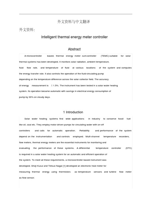
外文资料与中文翻译外文资料:Intelligent thermal energy meter controllerAbstractA microcontroller based, thermal energy meter cum controller (TEMC) suitable for solar thermal systems has been developed. It monitors solar radiation, ambient temperature,fluid flow rate, and temperature of fluid at various locations of the system and computes the energy transfer rate. It also controls the operation of the fluid-circulating pumpdepending on the temperature difference across the solar collector field. The accuracyof energy measurement is ±1.5%. The instrument has been tested in a solar water heatingsystem. Its operation became automatic with savings in electrical energy consumption ofpump by 30% on cloudy days.1 IntroductionSolar water heating systems find wide applications in industry to conserve fossil fuel like oil, coal etc. They employ motor driven pumps for circulating water with on-offcontrollers and calls for automatic operation. Reliability and performance of the system depend on the instrumentation and controls employed. Multi-channel temperature recorders, flow meters, thermal energy meters are the essential instruments for monitoring andevaluating the performance of these systems. A differential temperature controller (DTC) is required in a solar water heating system for an automatic and efficient operation ofthe system. To meet all these requirements, a microcontroller based instrument wasdeveloped. Shoji Kusui and Tetsuo Nagai [1] developed an electronic heat meter formeasuring thermal energy using thermistors as temperature sensors and turbine flow meter as flow sensor.2 Instrument detailsThe block diagram of the microcontroller (Intel 80C31) based thermal energy meter cum controller is shown in Fig. 1. RTD (PT100, 4-wire) sensors are used for the temperaturemeasurement of water at the collector field inlet, outlet and in the tank with appropriate signal conditioners designed with low-drift operational amplifiers. A precision semiconductor temperature sensor (LM335) is used for ambient temperature measurement. A pyranometer, having an output voltage of 8.33 mV/kW/m2, is used for measuring the incident solar radiation. To monitor the circulating fluid pressure, a sensor with 4–20 mA output is used. This output is converted into voltage using an I-V converter. All these outputsignals are fed to an 8-channel analog multiplexer (CD4051). Its output is fed to adual-slope 12-bit A/D converter (ICL7109). It is controlled by the microcontroller through the Programmable Peripheral Interface (PPI-82C55).Fig. 1. Block diagram of thermal energy meter cum controller.A flow sensor (turbine type) is used with a signal conditioner to measure the flowrate. Its output is fed to the counter input of the microcontroller. It is programmed tomonitor all the multiplexed signals every minute, compute the temperature difference,energy transfer rate and integrated energy. A real-time clock with MM58167 is interfacedto the microcontroller to time-stamp the logged data. An analog output (0–2 V) is provided using D/A converter (DAC-08) to plot both the measured and computed parameters. A 4×4 matrix keyboard is interfaced to the microcontroller to enter the parameters like specificheat of liquid, data log rate etc. An alphanumeric LCD display (24-character) is alsointerfaced with the microcontroller to display the measured variables. The serialcommunication port of the microcontroller is fed to the serial line driver and receiver(MAX232). It enables the instrument to interface with the computer for down-loading thelogged data. A battery-backed static memory of 56K bytes is provided to store the measured parameters. Besides data logging, the instrument serves as a DTC. This has been achievedby interfacing a relay to the PPI. The system software is developed to accept thedifferential temperature set points (ΔT on and ΔT off) from the keyboard. An algorithmsuitable for on-off control having two set-points is implemented to control the relays.3 Instrument calibrationThe amount of energy transferred (Q) is :Where = mass flows rate of liquid kg/s ; V = volumetric flow rate (l/h) ; ρ= density of water (kg/l) ; Cp = specific heat (kJ/kg°C); and ΔT = temperature difference between hot and cold (°C).The accuracy in energy measurement depends on the measurement accuracy of individual parameters. Temperature measurement accuracy depends on the initial error in the sensorand the error introduced due to temperature drifts in the signal conditioners and the A/D converter. The temperature sensor is immersed in a constant temperature bath (HAAKE B ath-K, German), whose temperature can be var ied in steps of 0.1°C. A mercury glass thermometer (ARNO A MARELL, Germany) with a resolution of 0.05°C is also placed along with PT100 sensor in the bath. This is compared with the instrument readings. The accuracy of the instrument in temperature measurem ent is ±0.1°C. Hence, the accuracy in differential temperature measurement is ±0.2°C.The flow sensor having a maximum flow rate of 1250 l/h is used for flow measurement.It is calibrated by fixing it in the upstream of a pipeline of length 8 m. The sensor output is connected to a digital frequency counter to monitor the number of pulses generated withdifferent flow rates. Water collected at the sensor outlet over a period is used forestimating the flow rate. The K-factor of the sensor is 3975 pulses/l. The uncertaintyin flow measurement is ±0.25% at 675 l/h. Uncertainties in density and specific heat ofwater are ±0.006 kg/l and ±0.011 kJ/kg°C respectively.Maximum amount of energy collection (Q) = 675×0.98×4.184×15/3600 = 11.53kW. Uncertainty in energy measurementωq/Q = [(ωv/V)2 + (ωρ/ρ)2 + (ωcp/Cp)2+(ωt/T )2]1/2.Inaccuracy in electronic circuitry is ±0.03 kW.The net inaccuracy in energy measurement is ±1.5%4 Field testThe instrument is incorporated in a solar water heating system as shown in Fig. 2.It consists of five solar flat plate collectors having an absorber area of 1.6 m2 each. The absorber is a fin and tube extruded from aluminium and painted with matt black paint. The collectors are mounted on a rigid frame facing south at an angle equal to the latitude of Bangalore (13°N). They are arranged in parallel configuration and connected to athermally insulated 500 l capacity storage tank. A 0.25 hp pump is used for circulatingthe water through the collector field. All the pipelines are thermally insulated. Thetemperature sensors and the flow sensor are incorporated in the system as shown in Fig.2. The data on solar radiation, ambient temperature, water flow rate, solar collector inlet and outlet temperatures and the system heat output are monitored at regular intervals.Fig. 2. Solar water heating system with thermal energy meter cum controller.The performance of the solar water heating system with TEMC on a partial cloudy dayis shown in Fig. 3. It is observed that DTC switched OFF the pump around 14:40 h as thereis no further energy gain by the collector field. This in turn reduced the heat lossesfrom the collector to ambient. Experiments are conducted with and without DTC o n both sunny and cloudy days. The DTC operated system shows the savings in electrical energy by 30%on a partial cloudy day and 8% on a sunny day. The variation in system output with andwithout DTC i s around 3%. Thus the controller has not only served as an energy conservation device, but also switches ON/OFF the system automatically depending on the availabilityof solar radiation. The collector field output (shown in Fig. 3) is calculated by measuring the fluid flow rate using volumetric method and the temperature difference with anotherpair of standard thermometers. It is 16.86 kWh. It is compared with the instrument reading 17.18 kWh. Thus, the deviation is 1.9%. Fig. 3 shows that the solar collector fieldefficiency is 54% when the incident solar irradiation is 31.75 kWh.Fig. 3. Performance of SWH system with TEMC on a partial cloudy day.5 Concluding remarksTEMC is used as on-line instrument in solar water heating systems for the measurement of thermal energy, temperature, flow rate with simultaneous control on the operation ofthe pump t o save electrical energy and enhance the thermal energy collection. Since several options are provided in the instrument, it can be used for monitoring the energy transfer rate in other thermal systems.AcknowledgementsThe authors are thankful to Department of Science and Technology, Govt. of India forproviding the financial assistance to carry out the above work.References1. Shoji Kusui, Tetsuo Nagai. An electronic integrating heat meter. IEEE Trans. onInstrumentation and Measurement, 1990;39(5):785-789.中文翻译:智能热能表控制器摘要适用于太阳能热系统的单片机热能表控制器(TEMC)已经研制成功。
- 1、下载文档前请自行甄别文档内容的完整性,平台不提供额外的编辑、内容补充、找答案等附加服务。
- 2、"仅部分预览"的文档,不可在线预览部分如存在完整性等问题,可反馈申请退款(可完整预览的文档不适用该条件!)。
- 3、如文档侵犯您的权益,请联系客服反馈,我们会尽快为您处理(人工客服工作时间:9:00-18:30)。
毕业设计外文文献翻译毕业设计题目温室大棚测控系统设计翻译题目智能红外温度传感器专业测控技术与仪器姓名班级学号指导教师机械与材料工程学院二〇一一年十月智能红外温度传感器跟上不断发展的工艺技术对工艺工程师来说是一向重大挑战。
再加上为了保持目前迅速变化的监测和控制方法的过程的要求,所以这项任务已变得相当迫切。
然而,红外温度传感器制造商正在为用户提供所需的工具来应付这些挑战:最新的计算机相关的硬件、软件和通信设备,以及最先进的数字电路。
其中最主要的工具,不过是新一代的红外温度计---智能传感器。
今天新的智能红外传感器代表了两个迅速发展的结合了红外测温和通常与计算机联系在一起的高速数字技术的科学联盟。
这些文书被称为智能传感器,因为他们把微处理器作为编程的双向收发器。
传感器之间的串行通信的生产车间和计算机控制室。
而且因为电路体积小,传感器因此更小,简化了在紧张或尴尬地区的安装。
智能传感器集成到新的或现有的过程控制系统,从一个新的先进水平,在温度监测和控制方面为过程控制方面的工程师提供了一个直接的好处。
1.集成智能传感器到过程线同时广泛推行的智能红外传感器是新的,红外测温已成功地应用于过程监测和控制几十年了。
在过去,如果工艺工程师需要改变传感器的设置,它们将不得不关闭或者删除线传感器或尝试手动重置到位。
当然也可能导致路线的延误,在某些情况下,是十分危险的。
升级传感器通常需要购买一个新单位,校准它的进程,并且在生产线停滞的时候安装它。
例如,某些传感器的镀锌铁丝厂用了安装了大桶的熔融铅、锌、和/或盐酸并且可以毫不费力的从狭窄小道流出来。
从安全利益考虑,生产线将不得不关闭,并且至少在降温24小时之前改变和升级传感器。
今天,工艺工程师可以远程配置、监测、处理、升级和维护其红外温度传感器。
带有双向RS - 485接口或RS - 232通信功能的智能模型简化了融入过程控制系统的过程。
一旦传感器被安装在生产线,工程师就可以根据其所有参数来适应不断变化的条件,一切都只是从控制室中的个人电脑。
举例来说,如果环境温度的波动,或程序本身经历类型、厚度、或温度的改变,所有过程工程师需要做的是定制或恢复保存在计算机终端的设置。
如果智能传感器由于高温度环境、电缆断裂或者未能组成部分而失败了,其故障进行自动修复。
该传感器激活触发报警停机,防止损坏产品和机械。
如果烤炉或冷却器失败了,音响和LO警报信号还可以指出哪里有问题并且关闭生产线。
1.1 延长传感器的使用寿命为了使智能传感器符合数千种不同类型的进程,就必须完全自己定义。
由于智能传感器包含只读(可擦除可编程只读存储器),用户可以重新编程以满足他们各自的具体程序要求使用的现场标定、诊断、或来自传感器制造商的实用软件。
另一个拥有智能传感器的好处是其固件,在其芯片的嵌入式软件,可通过通讯联系的升级来修订,因此它们成为可利用的-----不用从生产线移走传感器。
固件升级可以延长一个传感器的工作寿命,可以真正的使一个智能传感器智能化。
Raytek公司的马拉松系列的是一个全系列的1 - 2色比红外温度计,可以与多达32个智能传感器联网。
现有模式包括综合单位和光纤传感器的电子盒套来确保可在高温环境上安装。
点击一个传感器窗口显示了特定的传感器的配置设置。
Windows图形界面直观,易于使用。
在配置屏幕,工艺工程师能够监测电流传感器的设置,调整它们来满足他们的需要,或重置传感器回到工厂默认值。
所有显示的信息都来自经由RS - 485接口或RS - 232串口连接的传感器。
头两栏为了给用户输入,第三个为了在第一时间内监测传感器的参数,某些参数可以通过其他屏幕定制的程序和从PC到传感器的命令更改。
参数可以被用户通过以下方面来改变输入:•继电器触点可设定为NO (常开)或数控(通常关闭)。
•中继功能可设定警报或设定点。
•温度单位可以改变由摄氏度至华氏度,反之亦然。
•显示器和模拟输出模式可以改变的智能传感器,再加上一两色的容量。
•激光(如传感器配有激光瞄准)可以开启或关闭。
•毫安输出设置和范围,可作为自动进程触发或警报。
•发射率(1色)或斜率(两色)比热值可设定。
发射率和斜率值一般金属和非金属材料,并说明如何确定发射和斜坡,通常包含在传感器中。
•信号处理定义的温度参数返回,平均返回一个对象的平均气温在一段时间内;峰值举行返回一个对象的最高温度可能在一段时间内或由外部触发。
•音响报警/劳报警可设定警告不当温度的变化,在一些过程线,这可能是引发打破在一个产品或故障加热器或冷却器的内容。
•衰减表明报警并关闭设置双色比智能传感器,在这个例子中,如果镜头是95%遮蔽,报警警告说温度的结果可能是失去准确性(称为“肮脏的窗口”报警)。
95%以上可以默默无闻的触发一个自动关机的进程。
1.2 智能红外传感器的应用智能型红外传感器,可用于任何生产过程温度是至关重要的高品质的产品中。
红外温度传感器可以看到监控产品的各种热工前后和干燥前后的温度。
智能传感器上配置一个高速多点网络(定义见下文),并从远程监控的计算机上独立寻址。
各地的传感器测量的温度都可以以调查的数据单独或季度的绘制成图表,便于监测和温度数据过程的存档。
使用远程处理功能,设置点、报警器、发射率、和信号处理,信息可以被下载到每个传感器,其结果是更严格的过程控制。
1.3 远程在线寻址在一个持续的和图2相似的过程,智能传感器可以连接到一个或其他显示器。
图表记录器和控制器分别在一个单独网络。
该传感器可安排在多点或点对点配置,或者只是简单的独立。
在多点配置,多个传感器(多达32个在某些情况下)都可以联结到网络型电缆。
每个传感器都拥有自己的“地址”,允许它分别设定不同的操作参数。
由于智能传感器使用RS - 485接口或FSK信号(频移键控)的通信,他们可以从控制室的电脑设置相当大的距离---多达1200米( 4000英尺)的RS - 485接口,或3000米(一点零零零万英尺)的FSK信号。
有些程序使用RS - 232接口通信,但电缆的长度限制到100英尺。
在一个点对点的安装,智能传感器可以连接到图表记录、过程控制器、显示器、以及控制计算机。
在这种类型的安装,数字通信可结合毫安电流回路作为一个完整的全方位的进程通信软件包。
但是,有时专门的程序得需要专门软件。
一个壁纸制造商可能需要一系列的传感器编程来检查休息和眼泪沿着整个新闻界和涂层运行,但每个地区都有不同的环境和地表温度,如果发现表面的不正常现象,每个传感器必须触发警报。
例如为了满足客户商具体的要求,工程师们可以使用出版协议数据编写自己的程序。
这些自定义程序可以远程在飞虫身上安装传感器而不用关闭生产线。
2.刻度的标定和传感器的升级无论是使用多点、点对点、或单一的传感器网络,工艺工程师需要适当的软件工具在自己的个人计算机上来校准、配置、监控和升级这些传感器。
简单易于使用的数据采集、配置和实用程序通常是智能传感器套件购买时的一部分,或自定义的软件都可以使用。
与外地校准软件相比,智能传感器是可校准的。
新的参数直接下载到传感器的电路和传感器的当前参数被保存和存储为计算机数据文件,以确保完整记录校准和/或参数的变化保留。
一套校准技术,可以包括单点偏移和两到三点的可变温度:•单点抵消如果一个单一的温度在特定的过程中使用,传感器的读数需要重置,使其符合一个已知温度,单点偏移校准应使用。
这个偏移将适用于所有温度在整个温度范围内工作。
例如,如果一个已知的温度沿一个浮动的玻璃生产线是1800°F,智能传感器或一系列的传感器,都可以校准那个温度。
•两点如果传感器的读数必须符合两个特定的温度,这两个点在校准图3所示应选择。
这种技术使用校准温度来计算增益和偏移是适用于所有在整个温度范围内的温度。
•三点变温度如果这一进程具有广泛的温度范围,传感器的读数必须符合三个具体温度,最好的选择是3点变温度校准。
这种技术使用校准温度计算两个收益和两个偏移。
第一增益和偏移适用于所有低于中点温度并在第二盘以上所有的中点的温度。
三点校准和多单双点相比不太常见,但偶尔制造商需要执行此技术,以满足特定的标准。
现场校准软件还允许使用常规诊断方法,包括被运行在智能传感器上的电源电压和中继试验。
结果让工艺工程师知道传感器的效果最佳,并在其做出一些必要的故障排除更加容易。
3.结尾新一代的智能红外温度传感器要求工艺工程师必须跟上新的生产技术和产量增加所带来的变化。
他们现在可以配置尽可能多的传感器来满足他们特殊控制过程的需要并且延长这些传感器寿命,远远超出先前的“不聪明”的设计。
由于生产速度提高,设备停机时间必须减少。
通过尽可能的监测设备和微调温度变量而无需关闭的进程,工程师们可以保持高效率的过程和提供高质量的产品。
智能红外传感器的数字化处理组件和通讯能力提供一定程度的到现在都没有实现的灵活性、安全性和易用性。
红外线( IR )辐射是电磁波谱,其中包括无线电波、微波、可见光和紫外线,以及伽马射线和X射线。
IR是在可见部分的频谱和无线电波之间的。
红外波长通常以微米表示并且光谱范围由0.7至1000微米,只有0.7-14微米波段用于红外测温。
采用先进的光学系统和探测器,非接触式红外温度计就可以专注于几乎任何部分或0.7-14微米波段的部分。
因为每一个对象(除黑体)排放量的最佳红外能量在某一特定点沿线的红外波段,每个过程可能需要独特的传感器模型与具体的光学和探测器类型。
例如,一个传感器,一个狭窄的集中在3.43微米的频谱范围适合用于测量表面温度的聚乙烯和相关材料。
一个传感器设在5微米是用来衡量玻璃表面。
光传感器用于金属和金属箔片。
更广泛的光谱范围内用来衡量温度较低的表面,如纸、纸板、聚、和铝箔复合材料。
一个对象通过它的温度来体现排放红外能量增加还是减少。
它是发出能量,以目标发射率来测量,那表明了一个物体的温度。
发射率是一个术语,用于量化能源发光特性不同的材料和表面。
红外传感器具有可调发射率设定,通常是从0.1到1.0,使准确的测量的几个表面类型的温度。
发出的能量来自于一个对象,并通过其光学系统达到了红外传感器,其重点在能源上的一个或多个光敏探测器。
然后探测器的红外能量转换成电信号,而这又是转换成温度值基于传感器的校准方程和目标的发射率。
这一温度值可显示在传感器,或在一种智能传感器转换成数字输出,并显示在计算机终端。
Smart Infrared Temperature SensorsK eeping up with continuously evolving process technologies is a major challenge for process engineers. Add to that the demands of staying current with rapidly evolving methods of monitoring and controlling those processes, and the assignment can become quite intimidating. However, infrared (IR) temperature sensor manufacturers are giving users the tools they need to meet these challenges: the latest computer-related hardware, software, and communications equipment, as well as leading-edge digital circuitry. Chief among these tools, though, is the next generation of IR thermometers—the smart sensor.Today’s new smart IR sensors represent a union of two rapidly evolving sciences that combine IR temperature measurement with high-speed digital technologies usually associated with the computer. These instruments are called smart sensors because they incorporate microprocessors programmed to act as transceivers for bidirectional, serial communications between sensors on the manufacturing floor and computers in the control room (see Photo 1). And because the circuitry is smaller, the sensors are smaller, simplifying installation in tight or awkward areas. Integrating smart sensors into new or existing process control systems offers an immediate advantage to process control engineers in terms of providing a new level of sophistication in temperature monitoring and control.Integrating Smart Sensors into Process LinesWhile the widespread implementation of smart IR sensors is new, IR temperature measurement has been successfully used in process monitoring and control for decades (see the sidebar, “How Infrared Temperature Sensors Work,” below). In the past, if process engineers needed to change a sensor’s settings, they would have to either shut down the line to remove the sensor or try to manually reset it in place. Either course could cause delays in the line, and, in some cases, be very dangerous. Upgrading a sensor usually required buying a new unit, calibrating it to the process, and installing it while the process line lay inactive. For example, some of the sensors in a wire galvanizing plant used to be mounted over vats of molten lead, zinc, and/or muriatic acid and accessible only by reaching out over the vats from a catwalk. In the interests of safety, the process line would have to be shut down for at least 24 hours to cool before changing and upgrading a sensor.Today, process engineers can remotely configure, monitor, address, upgrade, and maintain their IR temperature sensors. Smart models with bidirectional RS-485 or RS-232 communications capabilities simplify integration into process control systems. Once a sensor is installed on a process line, engineers can tailor all its parameters to fit changing conditions—all from a PC in thecontrol room. If, for example, the ambient temperature fluctuates, or the process itself undergoes changes in type, thickness, or temperature, all a process engineer needs to do is customize or restore saved settings at a computer terminal. If a smart sensor fails due to high ambient temperature conditions, a cut cable, or failed components, its fail-safe conditions engage automatically. The sensor activates an alarm to trigger a shutdown, preventing damage to product and machinery. If ovens or coolers fail, HI and LO alarms can also signal that there is a problem and/or shut down the line.Extending a Sensor’s Useful LifeFor smart sensors to be compatible with thousands of different types of processes, they must be fully customizable. Because smart sensors contain EPROMs (erasable programmable read only memory), users can reprogram them to meet their specific process requirements using field calibration, diagnostics, and/or utility software from the sensor manufacturer.Another benefit of owning a smart sensor is that its firmware, the software embedded in its chips, can be upgraded via the communications link to revisions as they become available—without removing the sensor from the process line. Firmware upgrades extend the working life of a sensor and can actually make a smart sensor smarter.The Raytek Marathon Series is a full line of 1- and 2-color ratio IR thermometers that can be networked with up to 32 smart sensors. Available models include both integrated units and fiber-optic sensors with electronic enclosures that can be mounted away from high ambient temperatures.(see Photo 1). Clicking on a sensor window displays the configuration settings for that particular sensor. The Windows graphical interface is intuitive and easy to use. In the configuration screen, process engineers can monitor current sensor settings, adjust them to meet their needs, or reset the sensor back to the factory defaults. All the displayed information comes from the sensor by way of the RS-485 or RS-232 serial connection.The first two columns are for user input. The third monitors the sensor’s parameters in real time. Some parameters can be changed through other screens, custom programming, and direct PC-to-sensor commands. Parameters that can be changed by user input include the following:•Relay contact can be set to NO (normally open) or NC (normally closed).•Relay function can be set to alarm or setpoint.•Temperature units can be changed from degrees Celsius to degrees Fahrenheit, or vice versa.•Display and analog output mode can be changed for smart sensors that have combined one- and two-color capabilities.•Laser (if the sensor is equipped with laser aiming) can be turned on or off.•Milliamp output settings and range can be used as automatic process triggers or alarms.•Emissivity (for one-color) or slope (for two-color) ratio thermometers values can be set.Emissivity and slope values for common metal and nonmetal materials, and instructions on how to determine emissivity and slope, are usually included with sensors.•Signal processing defines the temperature parameters returned. Average returns an object’s average temperature over a period of time;peak-hold returns an object’s peak temperature either over a period of time or by an external trigger.•HI alarm/LO alarm can be set to warn of improper changes in temperature. On some process lines, this could be triggered by a break in a product or by malfunctioning heater or cooler elements.•Attenuation indicates alarm and shut down settings for two-color ratio smart sensors. In this example, if the lens is 95% obscured, an alarm warns that the temperature results might be losing accuracy (known as a “dirty window” alarm). More than 95% obscurity can trigger an automatic shutdown of the process.Using Smart SensorsSmart IR sensors can be used in any manufacturing process in which temperatures are crucial to high-quality product.Six IR temperature sensors can be seen monitoring product temperatures before and after the various thermal processes and before and after drying. The smart sensors are configured on a high-speed multidrop network (defined below) and are individually addressable from the remote supervisory computer. Measured temperatures at all sensor locations can be polled individually or sequentially; the data can be graphed for easy monitoring or archived to document process temperature data. Using remote addressing features, set points, alarms, emissivity, and signal processing, information can be downloaded to each sensor. The result is tighter process control. Remote Online AddressabilityIn a continuous process similar to that in Figure 2, smart sensors can be connected to one another or to other displays, chart recorders, and controllers on a single network. The sensors may be arranged in multidrop or point-to-point configurations, or simply stand alone.In a multidrop configuration, multiple sensors (up to 32 in some cases) can be combined on a network-type cable. Each can have its own “address,” allowing it to be configured separately with different operating parameters. Because smart sensors use RS-485 or FSK (frequency shift keyed) communications, they can be located at considerable distances from the control room computer—up to 1200 m (4000 ft.) for RS-485, or 3000 m (10,000 ft.) for FSK. Some processesuse RS-232 communications, but cable length is limited to <100 ft.In a point-to-point installation, smart sensors can be connected to chart recorders, process controllers, and displays, as well as to the controlling computer. In this type of installation, digital communications can be combined with milliamp current loops for a complete all-around process communications package.Sometimes, however, specialized processes require specialized software. A wallpaper manufacturer might need a series of sensors programmed to check for breaks and tears along the entire press and coating run, but each area has different ambient and surface temperatures, and each sensor must trigger an alarm if it notices irregularities in the surface. For customized processes such as this, engineers can write their own programs using published protocol data. These custom programs can remotely reconfigure sensors on the fly—without shutting down the process line.Field Calibration and Sensor UpgradesWhether using multidrop, point-to-point, or single sensor networks, process engineers need the proper software tools on their personal computers to calibrate, configure, monitor, and upgrade those sensors. Simple, easy-to-use data acquisition, configuration, and utility programs are usually part of the smart sensor package when purchased, or custom software can be used.With field calibration software, smart sensors can be calibrated, new parameters downloaded directly to the sensor’s circuitry, and the sensor’s current parameters saved and stored as computer data files to ensure that a complete record of calibration and/or parameter changes is kept. One set of calibration techniques can include one-point offset and two- and three-point with variable temperatures:•One-point offset. If a single temperature is used in a particular process, and the sensor reading needs to be offset to make it match a known temperature, one-point offset calibration should be used. This offset will be applied to all temperatures throughout the entire temperature range. For example, if the known temperature along a float glass line is exactly 1800°F, the smart sensor, or series of sensors, can be calibrated to that temperature.•Two-point. If sensor readings must match at two specific temperatures, the two-point calibration shown in Figure 3 should be selected. This technique uses the calibration temperatures to calculate a gain and an offset that are applied to all temperatures throughout the entire range.•Three-point with variable temperature. If the process has a wide range of temperatures, and sensor readings need to match at three specific temperatures, the best choice is three-point variable temperature calibration (see Figure 4). This technique uses the calibration temperatures to calculate two gains and two offsets. The first gain and offset are applied to all temperatures belowa midpoint temperature, and the second set to all temperatures above the midpoint. Three-pointcalibration is less common than one- and two-point, but occasionally manufacturers need to perform this technique to meet specific standards.Field calibration software also allows routine diagnostics, including power supply voltage and relay tests, to be run on smart sensors. The results let process engineers know if the sensors are performing at their optimum and make any necessary troubleshooting easier.ConclusionThe new generation of smart IR temperature sensors allows process engineers to keep up with changes brought on by newer manufacturing techniques and increases in production. They now can configure as many sensors as necessary for their specific process control needs and extend the life of those s ensors far beyond that of earlier, “non-smart” designs. As production rates increase, equipment downtime must decrease. By being able to monitor equipment and fine-tune temperature variables without shutting down a process, engineers can keep the process efficient and the product quality high. A smart IR sensor’s digital processing components and communications capabilities provide a level of flexibility, safety, and ease of use not achieved until now.How Infrared Temperature Sensors WorkInfrared (IR) radiation is part of the electromagnetic spectrum, which includes radio waves, microwaves, visible light, and ultraviolet light, as well as gamma rays and X-rays. The IRrange falls between the visible portion of the spectrum and radio waves. IR wavelengths are usually expressed in microns, with the IR spectrum extending from 0.7 to 1000 microns. Only the 0.7-14 micron band is used for IR temperature measurement.Using advanced optic systems and detectors, noncontact IR thermometers can focus on nearly any portion or portions of the 0.7-14 micron band. Because every object (with the exception of a blackbody) emits an optimum amount of IR energy at a specific point along the IR band, each process may require unique sensor models with specific optics and detector types. For example, a sensor with a narrow spectral range centered at 3.43 microns is optimized for measuring the surface temperature of polyethylene and related materials. A sensor set up for 5 microns is used to measure glass surfaces. A 1 micron sensor is used for metals and foils. The broader spectral ranges are used to measure lower temperature surfaces, such as paper, board, poly, and foil composites.The intensity of an object's emitted IR energy increases or decreases in proportion to its temperature. It is the emitted energy, measured as the target's emissivity, that indicates an object'stemperature.Emissivity is a term used to quantify the energy-emitting characteristics of different materials and surfaces. IR sensors have adjustable emissivity settings, usually from 0.1 to 1.0, which allowaccurate temperature measurements of several surface types.The emitted energy comes from an object and reaches the IR sensor through its optical system, which focuses the energy onto one or more photosensitive detectors. The detector then converts the IR energy into an electrical signal, which is in turn converted into a temperature value based on the sensor's calibration equation and the target's emissivity. This temperature value can be displayed on the sensor, or, in the case of the smart sensor, converted to a digital output and displayed on a computer terminal。