Pulldownit使用手册中文版
Pulldownit使用手册中文版
Pulldown It 1.7 使用手册(第一版)官方网站:么是Pulldownit?Pulldownit是一个全新的将破碎视作大规模刚体解算的动力解算器。
通过它的数字技术,艺术家能快速的模拟大量物体的场景、建筑物倒塌或者是各种易碎的物体。
快速准确的刚体解算器内置Pulldownit的RBD解算器是CG动力学多年的研究成果。
它在对模拟对象的数量没有限制,能够在几秒钟内计算数百人的碰撞。
它克服了其他解算器具有的的所有典型问题。
它精确的节省资源,计算正确物理摩擦(PCF)。
所有这些,保证了稳定,准确的模拟,而不是让物体飞走!破碎Voronoi-basedpre-cutting破碎,一个Pulldownit的新型预切割工具。
它是基于Voronoi图的,因为这是最好的最精确的破碎图案。
这个功能能在很短的时间能将3d物体预切割上百块碎片。
此外,生成的碎块在Pulldownit结算其中很容易的进行快速和准确的模拟。
破碎的能力Pdi内置的破碎能力是全新的,开创性的。
它可以打破任何易碎材料类似于石材,玻璃或水泥。
通过使用它的数字艺术,能够模拟在几分钟内模拟建筑物倒塌,如建筑物拆除。
它的易用性和强大的计算工具可以控制模拟完成创建的裂纹和控制器。
有好的动画设置Pdi集成了最优秀的3d套件。
它能获取集合体最终的视口计算结果作为最终的动画。
它允许重置模拟或者是重新计算任何一帧的参数更改和恢复模拟,此外,已经制作动画的物体或者角色也能模拟互相影响。
Pulldownit官方网站效果展示:一、破解方式:1,网上下载Pulldown it 1.7破解安装包,内部详细解压如下:2,将相应的文件夹复制(或者剪切)放到Maya的安装目录下:3,启动Maya(我的是2012版本64位),打开插件管理器,将pdiMaya勾选即可;4,之后会出现注册面板,破解版中,有注册的内容,在这里我就不再叙述了,一切搞定好,就可以使用这一款破碎很快速的插件了!工具架效果如下:二、Pulldownit1.7 面板翻译:第一部分破碎选项1.关于Num shards(碎片数):就是破碎的数目,这个数越大破碎时间就越久,此参数最高为4092,于是我们可以采用相继破碎的方式进行破碎,也就是,先破碎几块大的,然后在选中大的进行2次、3次、4次……破碎。
海港自由工具-2.5吨重量调整机械臂说明书
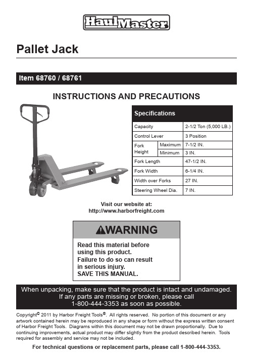
Pallet JackInstructIons and PrecautIonsVisit our website at:Copyright© 2011 by Harbor Freight Tools®. All rights reserved. No portion of this document or any artwork contained herein may be reproduced in any shape or form without the express written consent of Harbor Freight Tools. Diagrams within this document may not be drawn proportionally. Due to continuing improvements, actual product may differ slightly from the product described herein. Tools required for assembly and service may not be included.For technical questions or replacement parts, please call 1‑800‑444‑3353.1. Do not exceed 5,000 lb. capacity.Be aware of dynamic loading!Sudden load movement maybriefly create excess loadcausing product failure.2. Wear ANSI-approved safetygoggles, heavy-duty workgloves and non-skid footwearduring assembly and use.3. Use as intended only. Do notuse to support people or animalsor use for aircraft purposes.4. Keep clear of fork andload while raised.5. Only use on flat, levelsurface able to withstandweight of truck and load.6. Do not leave unattendedwhile under load.7. Only use with balanced,properly secured load.8. Inspect before every use; do notuse if parts loose or damaged.9. This product is not a toy. Donot allow children to playwith or near this item.10. Do not operate while under theinfluence of alcohol or drugs.11. Do not wear loose clothing orjewelry, and wear restrictivehair covering, as they can becaught in moving parts.12. Before each use, carefully inspectthe wheels, Handle Frame, Chassisand Handle for proper operation.Do not use the Jack unless allcomponents are operating properly.13. Maintain product labels andnameplates. These carry importantsafety information. If unreadableor missing, contact HarborFreight Tools for a replacement.Page 2For technical questions, please call 1‑800‑444‑3353.Item 68760 / 68761read the entIreImPortant safetyInformatIon sectionat the beginning of thisdocument including alltext under subheadingstherein before set up oruse of this product. handle assemblyYou will need to attach the Handleto the base of the Jack beforefirst use. Refer to the Parts Listsand Diagrams near the end ofthis manual for part numbers.Tighten hardware to no morethan 43 ft-lb, using a torquewrench (sold separately).1. Remove the three Screws (D611)from the Handle Bracket (D151). 2. Set the Handle (D610A or B) onthe Handle Bracket, making surethat the Chain (D612) and theAdjusting Bolt (D614) pass throughthe large opening in the center ofthe Handle Bracket and the holein the center of the Shaft (D153).3. Slide the Washers (D616)onto the Screws (D611) theninsert the Screws through theHandle into the Handle Bracket(D151) and tighten securely.4. Raise the Lever Plate (D132) andinsert the Adjusting Bolt (D614)into the slotted open end, keepingthe Adjusting Nut (D615) on theunderside of the Lever Plate.the Control leverThe Control Lever on the Handle has three positions: Raise, Drive and Lower.a.Figure 1HandleRaise - Move the Handle downto its lowest position. Pumpthe Handle frame up anddown to lift the Jack Forks.b. Drive - Move the Handle tothe center position. The JackForks do not change positionwhen in drive. This position isused when the load is movedfrom one location to another.c. Lower - Hold the Handle upin its highest position. Thisposition automatically movesthe Forks to their lowest level.This position is only in place aslong as you hold the Handle up.The Handle moves back to theDrive position when released.If the Handle does not functionproperly, make adjustments asdescribed in the following chartby turning the Adjusting Nut(D615). After each adjustment,check that all positions of thePage 3For technical questions, please call 1‑800‑444‑3353. Item 68760 / 68761Page 4For technical questions, please call 1‑800‑444‑3353.Item 68760 / 68761Control Lever function properly and re-adjust if needed.PositionProblemturn adjusting nut (D615)DriveForks rise instead of staying in neutral.Clockwise until pumping action does not raise forks.DriveForks lower,or lower when pumping handle is in Drive position.Counterclockwise until forks do not lower.LowerForks do not lower.Clockwise untilraising the ControlLever lowers the Forks.RaiseForks do notelevate.Counterclockwise until the Forkselevate whilepumping in the Raise position.Bleeding the hydraulic JackBefore every use, check that there is enough oil in the Jack by lowering the Forks, removing the Oil Plug (D149) from the Jack and filling the Jack with high quality hydraulic oil to the level of the fill hole.To Bleed the Jack of excess air:1. Hold the Control Lever up to itshighest position to lower the Forks.2. Remove the Oil Plug.3. Pump the Handle up anddown several times to push excess air out of the Jack.4. If needed add oil to thelevel of the oil fill hole.5. Replace the Oil Plug.read the entIre ImPortant safety InformatIon section at the beginning of this document including all text under subheadings therein before set up or use of this product.1. Hold the Control Lever in itshighest position to lower the Forks, then release the Control Lever. 2. Slide the Forks under the load,being careful to center the load over the Forks, and to have the main weight of the load resting as near as possible to the Steering Wheels.3. Push the Control Lever down tothe Raise position, then pump the Handle until the load is raised off the floor and is resting on the Forks.4. Move the Control Lever to theDrive position and wheel the load to the desired location.5. Hold the Control Lever in itshighest position to lower the Forks, then release the Control Lever.6. Slide the Forks out fromunder the load.7. When finished using the Jack, holdthe Control Lever in its highest position to Lower the Forks. 8. Store in a clean dry placeaway from children.PLease read tHe foLLoWInG carefuLLy THe ManuFacTuReR anD/OR DiSTRibuTOR HaS PROviDeD THe PaRTS LiST anD aSSeMbLy DiagRaM in THiS DOcuMenT aS a ReFeRence TOOL OnLy. neiTHeR THe ManuFacTuReR OR DiSTRibuTOR MakeS any RePReSenTaTiOn OR WaRRanTy OF any kinD TO THe buyeR THaT He OR SHe iS quaLiFieD TO Make any RePaiRS TO THe PRODucT, ORTHaT He OR SHe iS quaLiFieD TO RePLace any PaRTS OF THe PRODucT. in FacT, THe ManuFacTuReR anD/OR DiSTRibuTOR exPReSSLy STaTeS THaT aLL RePaiRS anD PaRTS RePLaceMenTS SHOuLD be unDeRTaken by ceRTiFieD anD LicenSeD TecHnicianS, anD nOT by THe buyeR. THe buyeR aSSuMeS aLL RiSk anD LiabiLiTy aRiSing OuT OF HiS OR HeR RePaiRS TO THe ORiginaL PRODucT OR RePLaceMenT PaRTS THeReTO,OR aRiSing OuT OF HiS OR HeR inSTaLLaTiOn OF RePLaceMenT PaRTS THeReTO.Record Serial number here:note:If product has no serial number, recordmonth and year of purchase instead.note:Some parts are listed and shown for illustration purposesonly, and are not available individually as replacement parts.Item 68760 / 68761Page 5 For technical questions, please call 1‑800‑444‑3353.read the entIre ImPortant safety InformatIon sectionat the beginning of this document including all text undersubheadings therein before set up or use of this product.1. Lower Jack completely after every use.2. Periodically use motor oil or grease to lubricate all moveable parts.3. Replace handle if pin breaks.Page 6For technical questions, please call 1‑800‑444‑3353.Item 68760 / 68761Item 68760 / 68761Page 7 For technical questions, please call 1‑800‑444‑3353.Page 8For technical questions, please call 1‑800‑444‑3353.Item 68760 / 68761PartDescription QtyD601Spring1D602Blade Spring 1D603Roller1D604Elastic Pin 1D605Elastic Pin 1D606Elastic Pin 1D607Elastic Pin1D608Control Handle 1D609Pull Board1PartDescription QtyD610B Handle (For Type A)1D610A Handle (For Type B)1D611Screw 3D612Chain 1D613Pin1D614Adjusting Bolt 1D615Adjusting Nut 1D616Washer3Page 9For technical questions, please call 1‑800‑444‑3353.Item 68760 / 68761PartDescription QtyD201Screw 1D202Oil Holder 1D203Rocker arm 1D204Elastic Pin 1D205Retaining Ring 2D206Joint (For Type A)2D206D Joint (For Type B)2D207Shaft2D208Push Rod (For Type a)2D208D Push Rod (For Type b)2D209Nut (For Type A)2D209D Nut (For Type B)2D210Pin 2D211Shaft 1D212Shaft2D213Elastic Pin 2D214Shaft2D215Roller Frame2PartDescription QtyD216Elastic Pin 2D217Roller Shaft 4D218Fork Frame 1D219Washer 4D220Bearing4D221Loading Roller 4D222Linking Plate 4D223Elastic Pin 8D224Bushing 4D225Bushing 2D226Bolt2D227enter Roller 2D228Nut2D229Loading Roller 2D230Roller Shaft 2D231Washer 2D232Washer4Part Description Qty D101Pump Piston Rod1 D102Washer1 D103Spring1 D104Dust Ring1 D105Y-Seal1 D106Screw (For Type A)1 D106B Screw (For Type B)1 D107O-Ring (For Type a)1 D107B O-Ring (For Type b)1 D108Spring1 D109Pumping valve Spindle1 D110Pumping valve Seat(For Type A)1 D110B Screw (For Type B)1 D111O-Ring (For Type a)1 D111B O-Ring (For Type b)1 D112Steel Ball1 D113Pump Base1 D115Elastic Pin1 D116Steering Wheel2 D118Thrust Plate1 D119Oil Holder1 D120Retaining Ring1 D121Bearing Cover1 D122Bearing1 D123Elastic Pin2 D124Dust Cover2 D127Bearing4 D129Spring1 D130Strike Pin1Part Description Qty D131O-Ring2 D132Lever Plate1 D133Adjusting Screw1 D134Nut1 D135O-Ring1 D136Axle Sleeve1 D137Adjusting Bolt1 D139Safety valve Spindle1 D140Spring1 D141O-Ring1 D142Screw1 D143O-Ring1 D144Y-Seal1 D145Elastic Pin1 D146Steel Ball1 D147Piston Rod1 D148Dust Ring1 D149Oil Plug1 D150Shaft1 D151Handle Bracket1 D152Pressure Roller1 D153Shaft1 D154Elastic Pin1 D155Elastic Pin1 D156Bushing1 D157Seal Washer1 D158Bushing2 D159B Sleeve (For Type B)1 D160B Screw (For Type B)1Page 10For technical questions, please call 1‑800‑444‑3353.Item 68760 / 68761For technical questions, please call 1‑800‑444‑3353.Page 11Harbor Freight Tools Co. makes every effort to assure that its products meet high quality and durability standards, and warrants to the original purchaser that this product is free from defects in materials and workmanship for the period of 90 days from the date of purchase. This warranty does not applyto damage due directly or indirectly, to misuse, abuse, negligence or accidents, repairs or alterations outside our facilities, criminal activity, improper installation, normal wear and tear, or to lack of maintenance. We shall in no event be liable for death, injuries to persons or property, or for incidental, contingent, special or consequential damages arising from the use of our product. Some states do not allow the exclusion or limitation of incidental or consequential damages, so the above limitationof exclusion may not apply to you. THiS WaRRanTy iS exPReSSLy in Lieu OF aLL OTHeR WaRRanTieS, exPReSS OR iMPLieD, incLuDing THe WaRRanTieS OF MeRcHanTabiLiTy AND FITNESS.To take advantage of this warranty, the product or part must be returned to us with transportation charges prepaid. Proof of purchase date and an explanation of the complaint must accompany the merchandise. if our inspection verifies the defect, we will either repair or replace the product at our election or we may elect to refund the purchase price if we cannot readily and quickly provide you with a replacement. We will return repaired products at our expense, but if we determine there is no defect, or that the defect resulted from causes not within the scope of our warranty, then you must bear the cost of returning the product.This warranty gives you specific legal rights and you may also have other rights which vary from state to state.3491 mission Oaks Blvd. • PO Box 6009Camarillo, Ca 93011 • (800) 444‑3353。
Pulldownit
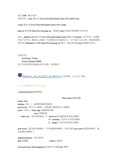
适合2009--2012版本安装方法:icons放在C:\Users\Tracy\Documents\maya\2011\prefs\iconsscripts放在C:\Users\Tracy\Documents\maya\2011\scriptsplug-ins放在E:\Maya2011\bin\plug-ins,就是你maya安装目录的插件文件夹里。
注意:pdiMaya.txt放在C:\Users\Tracy\Documents\maya\2011的modules文件夹里,如果没有这个文件夹,那你自己创建一个这样的文件夹就可以了,打开这个文本文件,把原来的路径改为+ Thinkinetic 1.0 E:\Maya2011\bin\plug-ins即可,就是该为你maya的插件文件夹。
注册方法:UserName: T-mcikLicense Number:00000用户名和注册号码输进去即可注册,欢迎使用Pulldownit__Pro_Ver_1[2].7_for_MAYA.rar(3.04 MB, 下载次数: 518)以下是Pulldownit的使用手册:1.shatterIt feature(破碎物体):Num shards:破碎面数shatter styleuniform(统一):就是整体破碎的意思。
pivot based(基于中心破碎):即使基于物体的中心来破碎。
radial(径向):Num rings是破碎的环数noise是噪波值radial axis:是径向的轴向:S(shortest)是以最短的边来径向破碎。
M(medium)是以中心来径向破碎。
L(longest)是以长边来径向破碎,path based(基于路径来破碎):可用曲线来画路径,然后在按select path来选择该路径,就会沿路径来破碎了。
original geometry(原几何体)hide是隐藏remove是移动create pdi object from fragments是从碎片中创建pdi 物体。
悉尼自由行 2 英寸接驳架说明书
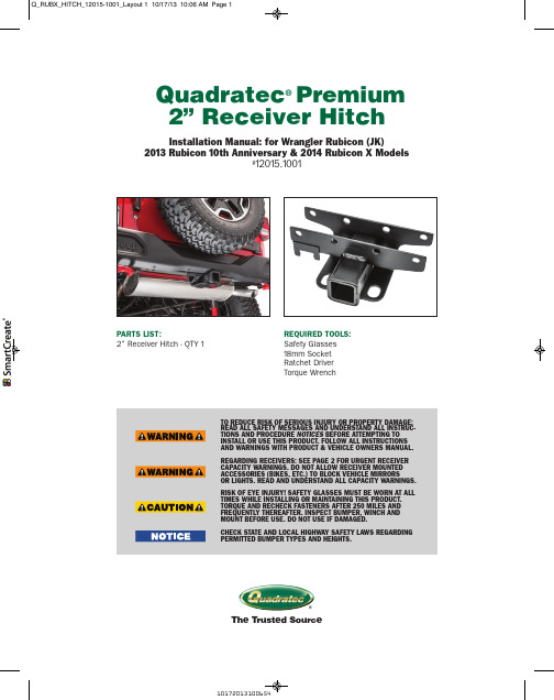
The Trusted Source®Quadratec ®Premium 2” Receiver Hitch TO REDUCE RISK OF SERIOUS INJURY OR PROPERTY DAMAGE:READ ALL SAFETY MESSAGES AND UNDERSTAND ALL INSTRUC-TIONS AND PROCEDURE NOTICES BEFORE ATTEMPTING TO INSTALL OR USE THIS PRODUCT. FOLLOW ALL INSTRUCTIONS AND WARNINGS WITH PRODUCT & VEHICLE OWNERS MANUAL.REGARDING RECEIVERS: SEE PAGE 2 FOR URGENT RECEIVER CAPACITY WARNINGS. DO NOT ALLOW RECEIVER MOUNTED ACCESSORIES (BIKES, ETC.) TO BLOCK VEHICLE MIRRORS OR LIGHTS. READ AND UNDERSTAND ALL CAPACITY WARNINGS.RISK OF EYE INJURY! SAFETY GLASSES MUST BE WORN AT ALL TIMES WHILE INSTALLING OR MAINTAINING THIS PRODUCT.TORQUE AND RECHECK FASTENERS AFTER 250 MILES AND FREQUENTLY THEREAFTER. INSPECT BUMPER, WINCH AND MOUNT BEFORE USE. DO NOT USE IF DAMAGED.CHECK STATE AND LOCAL HIGHWAY SAFETY LAWS REGARDING PERMITTED BUMPER TYPES AND HEIGHTS.Installation Manual: for Wrangler Rubicon (JK)2013 Rubicon 10th Anniversary & 2014 Rubicon X Models#12015.1001PARTS LIST:2” Receiver Hitch - QTY 1REQUIRED TOOLS: Safety Glasses18mm SocketRatchet DriverTorque WrenchTHIS CLASS II RECEIVER: 4 DOOR JK: MAX TOW WEIGHT 3500 LBS. MAX TONGUE WT. 300 LBS.4 DOOR JK: MAX TOW WEIGHT 2000 LBS. MAX TONGUE WT. 200 LBS.TO REDUCE RISK OF SERIOUS INJURY OR PROPERTY DAMAGE:INSTALL ACCORDING TO INSTRUCTIONS. TORQUE AND RECHECK FASTENERS AFTER 250 MILES AND FREQUENTLY THEREAFTER.INSPECT AND DO NOT USE RECEIVER/BUMPER IF DAMAGED.CONSULT & NEVER EXCEED LESSER OF VEHICLE, RECEIVER OR TRAILER MAXIMUM TOW OR WEIGHT RATINGS. CONSULT AND FOLLOW ALL LIMITATIONS & WARNINGS IN YOUR VEHICLE OWNERS MANUAL AND SAFE TOWING SUPPLEMENT.CHECK STATE AND LOCAL HIGHWAY SAFETY LAWS REGARDING PERMITTED BUMPER TYPES AND HEIGHTS.The Trusted Source®Before You Begin Installation: Congratulations on your purchase of the Quadratec Premium 2” Receiver Hitch for (2013 to current) 10th AnniversaryRubicon and Rubicon X Wrangler JK Vehicles. This version is specifically designed for this original equipment fac-tory bumper.When unpacking, check to make sure all parts are included and not damaged due to shipping.If any part is missing or broken, please call Customer Service at 800-745-6037as soon as possible.As tow hitches tend to be heavy, we suggest you get help for steps involving lifting, locating or holding the hitch dur-ing installation.Thank you again for your purchaseand let’s start the installation process.a hazardous situation which, if not avoided, could result in death or serious injury. You CAN be KILLED or SERIOUSLY HURT if you don’t follow instructions.a hazardous situation which, if not avoided, could result in minor or moderate injury. You CAN be moderately HURT and also may suffer property damage if you don’t follow instructions.Careful attention is required to this instruction or operation but does generally not relate to personal injury. Damage to your Quadratec ®product or other property may result if you don’t follow instructions. A Few Words About Product Safety: Your Receiver Hitch is intended toenhance the utility and enjoyment of your off road capable vehicle. Before installation, please take a moment to review the following safety information and installation instructions. Important safety information is generally preceded by one of three signal words indicating the relative risk of injury.The signal words mean:The Trusted Source®Hitch Installation:Install the hitch over the rear cross member, then reinstall the 4 factory bolts through the hitch and rear cross member and thread them intothe factory bumper. As shown in Fig. 4Torque the bolts to 80 ft.lbs. using an 18mm socket and a torque wrench. Put on safety glasses. Remove the 4factory bolts on the rear cross member of the vehicle using an 18mm wrench or socket. Be careful, the spacer plate may fall out of the bumper when removing the bolts. Remove and discard the fac-tory spacer plate and retaining washers.These will not be needed when in-stalling the Quadratec Premium 2”Receiver Hitch.Figure 1Figure 2Figure 3Figure 4The Trusted Source®Quadratec ® Exclusive Three Year Limited Warranty Your Quadratec ®branded accessories are covered by the following Limited Warranty provided exclusively by Quadratec, Inc., 1028Saunders Lane, West Chester PA 19380.This Limited Warranty is the only warranty made in connection with your purchase.Quadratec neither assumes nor authorizes any vendor, retailer or other person or entity to as-sume for it any other obligation or liability inconnection with this product or Limited War-ranty . This Limited Warranty does not apply and is not cumulative to any accessory or part distributed by Quadratec for which the Manu-facturer provides a separate written warranty. What is Covered: Subject to the terms, exclu-sions and limitations herein and with respect only to Quadratec branded accessories first sold in the United States, Quadratec warrants to the initial retail purchaser only that your Quadratec accessory shall be free of defects inmaterial and workmanship: for a period of three (3) years from date of retail purchase.This Limited Warranty is not assignable and shall terminate upon sale of the vehicle upon which the Quadratec accessory is installed or other transfer third persons.All other warranties are hereby disclaimed, ex-cept to the extent prohibited by applicable law in which case any implied warranty of mer-chantability or fitness for a particular purposeon this product is limited to 3 year from date of initial retail sale. Quadratec reserves the rights to: (a.) require invoice or other proof your ac-cessory is within the terms of this Limited Warranty as a condition of warranty service and, (b.) make future revisions to this product and Limited Warranty without prior notice or obligation to upgrade your product.What is Not Covered:Your Quadratec Limited Warranty does not cover products or parts Quadratec determinesto have been damaged by or subjected to:(a.) installation damage, alteration, modifica-tion, combination with other parts, failure to maintain or improper repair or service, (b.) nor-mal wear & tear, cosmetic damage or damagefrom moisture or water immersion, (c.) Acts ofGod, accidents, misuse, negligence, inadequate mounting or impact with vehicle(s), obstacles or other aspects of the environment, (d.) theft,vandalism or other intentional damage.Remedy Limited to Repair/Replacement:The exclusive remedy provided hereunder shall,upon Quadratec inspection and at Q uadratec’s option, be either repair or replacement of prod-uct or parts (new or refurbished) covered underthis Limited Warranty.Customers requestingwarranty consideration should first contact Quadratec to obtain a RGA number (610-701-3336). All labor, removal, shipping and installation costs are customer’s responsibility.Other Limitations - Exclusion of Damages -Your Rights Under State Law:In consideration of the purchase price paid, nei-ther Quadratec nor any independent Quadratec distributor/licensee are responsible for any time loss, rental costs, or for any incidental, conse-quential, punitive or other damages you mayhave or incur in connection with any part orproduct purchased. Your exclusive remedy hereunder for covered parts is repair/replace-ment as described above.This Limited Warranty gives you specific rights.You may also have other rights that vary from state to state. For example, some states do not allow limitations of how long an implied war-ranty lasts and /or do not allow the exclusion or limitation of incidental or consequential damages, so the limitations and exclusions herein may not apply to you.©Quadratec, Inc. 2013. All Rights Reserved.10.17.13 LTR Version Part #12999.3008。
利达懒人调试工具使用说明书

调试工具说明书编制人:谢雷2015年10月7日目录一、工具概况 (3)二、工具主要功能介绍 (3)1.区码查询 (3)2.128E2密码设置 (3)3.BIN文件导出 (3)4.极速开点 (4)a.初始化 (4)b.打开编码 (4)C.回路 (4)d.地址1 (4)e.地址2 (5)f.设备类型 (5)g.中文定义填写介绍 (5)h.房间号 (6)5.超级逻辑书写 (6)a.联动关系表格 (6)b.主机类型选择 (6)c.逻辑规则 (6)d.匹配的类型 (7)e.匹配中文定义 (8)f.逻辑识别输出原理 (9)三、工具使用步骤 (9)1.初始化懒人数据,初始化编码表! (9)2.打开编码表,填写完编码表,保存,点击极速开点! (9)3.打开编码表,填写联动关系,保存,点击超级逻辑书写按钮! (9)4.将生产的逻辑全选复制到懒人数据的逻辑规则中! (9)6.打开调试软件读取懒人数据,这样就OK了! (10)一、工具概况针对128E2、128EQ类主机调试开点繁琐,逻辑书写易出错,效率不搞的问题,为此基于按键精灵平台开发了懒人调试工具。
本工具基于按键精灵平台开发,仅供交流学习,作者不承担软件使用产生的一切后果,若不同意请勿使用软件,若有疑问请联系作者谢工:。
本工具运行杀毒软件可能会报毒,请加入白解除阻止,或者直接退出杀毒软件,普通电脑只需要安装一个完整的office软件即可正常工作,若遇到到开点失败的情况,这种情况一般出现于系统自带的office被阉割掉了,请重新安装office软件,精简版的office2003和07格式兼容包可以到QQ群282168780共享文件中下载。
本工具主要功能:128E2主机密码读取与设置、128EQ系列位置区位码查询、老EQ 芯片数据BIN文件数据解析导出功能、128E2和128EQ系列主机极速开点和超级逻辑自动书写功能,若有新的需求和意见请与作者沟通!二、工具主要功能介绍1.区码查询如下图填写待查词组即可:2.128E2密码设置如下图:点击读取密码即可读取调试目录下“C:\懒人调试\DATNET \pass.dat “的密码点击密码设置即可设置调试目录下“C:\懒人调试\DATNET \pass.dat “的密码3.BIN文件导出点击BIN文件导出按钮得到,BIN文件数据解析界面,如下图:按图中的使用说明进行操作即可,由于此功能使用频率相当小,这里就一笔带过,若有不清楚的请联系作者。
迈达斯IsatPhone Pro与IsatDock DRIVE手机掌柜说明书

IsatDock DRIVEIsatDock DRIVEKEY FEATURESISD DriveHands-free callingAlert & tracking functionalityCompact installationSupports privacy handsetTRACKING/ALERT MONITORINGTECHNICAL SPECIFICATIONS AVERAGE POWERCONSUMPTIONCURRENT @ 12VAVERAGE WATTS Power w/o IsatPhone Pro130mA 1.6W Standby + Charging360mA 4.3W Transmit + Charging875mA10.5W Sleep Mode5mA60mW Peak Current 3.5A42W PHYSICAL SPECIFICATIONSDimensions 230 x 84 x 80(mm)9.1 x 3.3 x 3.2(inches)Weight - Dock0.67kg 1.47lbs Total Kit Weight 1.67kg 3.68lbs ENVIRONMENT SPECIFICATIONSOperating Range-30°C to +70°C-22°F to +158°F Storage-35°C to +85°C-31°F to +185°F Battery Charging Temp#0°C to +45°C32°F to +113°F Humidity<= 75% RH GPS MODULE (INTERNAL)Channels14 tracking, 51 Channel Acquiring Update Rate1HzAccuracy Position 2.5mCEP, Velocity 0.1m/s,Timing 300nsAcquisition TTFF Cold 29sec, Hot 1secSensitivity--161 dBmOperational Limits Altitude 18000m , Velocity 515m/s Dynamics4GI/O ALARM/ALERTAlert Button In-built Two button press1 x alarm loop Bare wire - ‘‘Normally Closed’’ loopIN to OUTTrack button built-in In-built - single key press CONNECTORS / INTERFACESInmarsatAntenna TNC-FemaleGPS Antenna SMA-Female10-32 Volt DC4-way microFit (AC/DC adaptor, or DC lead) Privacy HandsetPort RJ9 connectorSpeaker2-way microFitMicrophone2-way microFitConfigurations/DataUSB microCERTIFICATIONSInmarsat Type ApprovalFCCCE ComplianceElectrical SafetyRoHSIndustry CanadaC-TickEMC complianceACCESSORIESISD715IsatDock Transport Active Antenna (Magnetic) ISD720IsatDock Transport Active Antenna (Bolt)ISD932IsatDock 6m SMA/TNC Active cable kitISD933IsatDock 13m SMA/TNC Active cable kit ISD934IsatDock 18m SMA/TNC Active cable kit ISD935IsatDock 31m SMA/TNC Active cable kit ISD955Privacy HandsetRST055Beam UPS Battery PackRST410Alert Pendant kitKlT CONTENTSIsatDock DRIVE10-32V DC power cableUniversal mounting bracket (RAM)Handset locking keyUser manual & Quick start guideSpeaker & Microphone# It is ideal for the ambient temperature to be approximately 18 degrees below the 45°C upper limit for the handset to charge the battery whilst docked.ISDDRIVE_REV00_00/00。
飞线网绊线鸟扑挫系统安装指南说明书
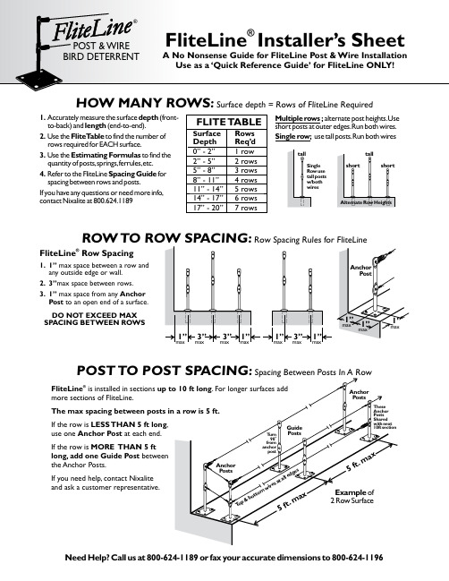
HOW MANY ROWS:Surface depth = Rows of FliteLine Required1.depth Accurately measure the surface(front-to-back)and(end-to-end).length2.FliteT ableUse the to find the number of rows required for EACH surface.3.Estimating FormulasUse the to find the quantity of posts,springs,ferrules,etc.4.Spacing Guide Refer to the FliteLine for spacing between rows and posts.If you have any questions or need more info, contact Nixalite at800.624.1189FLITE T ABLES urfaceRowsDepth Req’d0”- 2” 1 row2”- 5” 2 rows5”- 8” 3 rows8”- 11” 4 rows11”- 14” 5 rows14”- 17” 6 rows17”- 20”7 rowsMultiple rows;alternate post eshort posts at outer edges.Run both wires.Single row;use tall posts.Run bothwiresusepostsFliteLine Row Spacing®1.1”max space between a row andany outside edge or wall.2.3”max space between rows.3.1”Anchormax space from anyPost to an open end of a surface.DO NOT EXCEED MAXSPACING BETWEEN ROWSROW Row Spacing Rules for FliteLine Need Help?Call us at800-624-1189or fax your accurate dimensions to800-624-1196 FliteLine®is installed in sectionsmore sections of FliteLine.If the row is,LESS THAN 5 ft longuse one at each end.Anchor PostIf the row is MORE THAN 5 ftlong,add one Guide Post betweenthe Anchor Posts.If you need help,contact Nixaliteand ask a customer representative.POSTClean the surface firstMasonry:1/4”dia.hole,1-1/8”deep Drill .InsertAnchor,drive Nail Point Flite Post into anchor with hammer.Installed post height is 3.5”for short posts,5”for tall posts.Wood:to prevent splitting,drill small pilot holes,1”deep.Drive Nail Point Flite Post into wood with hammer.Installed post height -3.5”for short posts;5”for tall posts.Sheet Metal:position Flite Post w/base,mark hole locations,drill small pilot holes and secure each post with at least 2Sheet Metal Screws .Steel/Iron:position Flite Post w/base,mark hole locations,drill at least 2-.Secure each post 5/32”holes,½”deep or through with at least 2Drive Screws.Adhesive not recommended e mechanical fasteners when possible.Follow adhesive manufacturer’s instructions.Glue Flite Post w/base to the surface.Allow to then install wires.fully cure Wood Sheet MetalDouble check installed post heights for masonry and wood installations.HARDWARE STEPS - Installing FliteLine Hardware & PostsMasonryClean the Surface thoroughlyCable to Spring connection1.Mark the locations for all posts.2.AnchorBefore fastening,turn all Posts in-line with the cable.3.Guide Posts 90T urn all of the ofrom the cable.4.Install the Flite Posts using theHardware Steps instructions.5.Cable to Post Connection .Slide a ferrule onto the cable,loop the cable through the post eyelet and back through the ferrule.Push the ferrule to the post while pulling the cable tight.Crimpferrule tight and trim excess cable.Thread the cable through any Guide Posts (not shown).6.Cable to Spring Connection .Insert the open end of the spring through a hole on a post.Slide a ferrule onto the cable,loop the cable through the spring eyelet and back through the ferrule.Push the ferrule to the spring while pulling the cable tight.T ension the cable so it is straight but the spring is not extended.Crimp the ferrule and trim excess cable.NOTE:Stagger spring connections.Donot install 2 springs on one post.7.Install upper and lower cablesat all Outside Edges.Install Gate Cables at all Open Ends.8.Finished installation should havestraight evenly spaced rows,with double cable at all outside edges.1.Clearly mark all post and row locations4. 2. 3.5. 6.Make Sure Anchor Postsare in line with cable Make Sure Guide Posts are 90to o cableINSTALLING FLITELINE - Post layout,installation and cable connectionsgate cableboth cables7.8.Finished installFliteLine has many more uses than what are shown here.If you have a bird control problem and are not sure which Nixalite bird control system to use,call us.We can recommend the system that best suits your application.Questions?Contact Nixalite P:800.624.1189P:309.755.8771F:800.624.1196F:Copyright© 2014 byNixalite® of America Inc. All rights reserved.Nixalite® is a registered trademarkof Nixalite® of America Inc.Printed with pride in the USA.Anchors may bedifferent than what is shownFliteLine ®is a fully registered trademark of Nixalite ®of America Inc Nixalite®is a fully registered trademark of Nixalite®of America Inc102516th AvenueEast Moline,IL.61244Nixalite of America Inc®Experts In Architectural Bird Control Since 1950。
SPX 1526两速搬运杆说明书
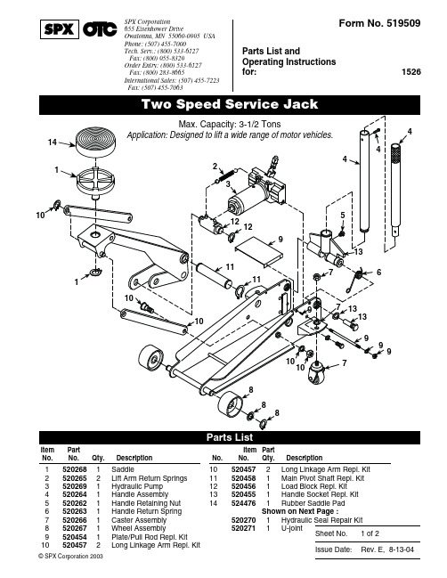
Sheet No.Issue Date:Rev. E, 8-13-04© SPX Corporation 2003Form No. 5195091 of 2Parts List andOperating Instructions for:1526SPX Corporation655 Eisenhower DriveOwatonna, MN 55060-0995 USA Phone: (507) 455-7000Tech. Serv.: (800) 533-6127 Fax: (800) 955-8329Order Entry: (800) 533-6127 Fax: (800) 283-8665International Sales: (507) 455-7223 Fax: (507) 455-7063Item Part No.No.Qty.Description15202681Saddle25202652Lift Arm Return Springs 35202691Hydraulic Pump 45202641Handle Assembly 55202621Handle Retaining Nut 65202631Handle Return Spring 75202661Caster Assembly 85202671Wheel Assembly95204541Plate/Pull Rod Repl. Kit 105204572Long Linkage Arm Repl. KitItem Part No.No.Qty.Description105204572Long Linkage Arm Repl. Kit 115204581Main Pivot Shaft Repl. Kit 125204561Load Block Repl. Kit 135204551Handle Socket Repl. Kit 145244761Rubber Saddle Pad Shown on Next Page :5202701Hydraulic Seal Repair Kit 5202711U-jointParts List & Operating InstructionsForm No. 519509, Back of Sheet 1 of 231O-ring41Plug Screw 51O-ring61O-ring Retainer 71O-ring81Copper Washer 91O-ring 102O-ring 111Washer122Filter Screen 131Copper Washer 142O-ring362Backup RingNo. 520271 U-joint Kit includes :151Ball 161O-ring171Release AssemblyBleeding Air from the SystemAir can accumulate within a hydraulic system during shipment or if the oil supply runs too low. This entrapped air causes the jack to respond slowly or feel “spongy.” The following procedure bleeds air from the system.1.Remove the jack from service, and place it on a level surface.2.Open the release valve by turning the handle all the way counterclockwise (CCW).3.Pump the handle six full strokes.4.Close the release valve by turning the handle all the way clockwise (CW).5.Pump the handle until the lift arm is fully extended.6.Lower the lift arm by turning the handle all the way counterclockwise (CCW).7.Test the jack for normal operation. If the lift pad doesn’t rise to the correct height, repeat Steps 2–6. If this doesn’t solve the problem, call the OTC Technical Services Dept. at (800) 533-6127.ItemNo.Qty.DescriptionNo. 520466 Hyd. Hardware Kit includes :181Retaining Ring 191Screw 201Spring 213Ball 221Rod 232Screw 241Spring 252Ball 261Rod 272BallItemNo.Qty.DescriptionNo. 520467 Hyd. Pump Station Kit includes :131Copper Washer 281High Plunger 291Metal Washer301Lower Protection Sleeve 311Spring321Upper Protection Sleeve 331Connection Washer 341Cotter Pin 351Plunger362Backup Ring 142O-ring23Sheet No.Issue Date:Rev. E, 8-13-04© SPX Corporation 2003Parts List & Operating InstructionsForm No. 519509CAUTION: To prevent personal injury and damage to equipment,•Read, understand, and follow all instructions, including ASME PAL D Part 10 for service jacks.If the operator cannot read English, operating instructions and safety precautions must be read and discussed in the operator’s native language.–Si el operador no puede leer inglés, las instrucciones de operación y las precauciones de seguridad deberán leerse y comentarse en el idioma nativo del operador.–Si l’utilisateur ne peut lire l’anglais, les instructions et les consignes de sécurité doivent lui être expliquées dans sa langue maternelle.•Before using the service jack to lift a vehicle, refer to the vehicle service manual to determine recommended lifting surfaces on the vehicle chassis.•Wear eye protection that meets ANSI Z87.1 and OSHA standards.•Inspect the jack before each use; do not use the jack if it’s damaged, altered, or in poor condition. Take corrective action if any of the following conditions are found: cracked or damaged housing; excessive wear, bending, or other damage; leaking hydraulic fluid;scored or damaged piston rod; loose hardware; modified or altered equipment.• A load must never exceed the rated lifting capacity of the jack.•Use the jack on a hard, level surface. The jack must be free to roll without any obstructions while lifting or lowering the vehicle. The wheels of the vehicle must be in the straight-ahead position, and the hand brake released.•Use the jack for lifting purposes only. Stay clear of a lifted load. Place support stands under the axles before working on the vehicle.•Center the load on the jack saddle. Off-center loads can damage seals and cause jack failure. Lift only dead weight.•Do not use blocks or other extenders between the saddle and the load being lifted.•Do not modify the jack or use adapters unless approved or supplied by OTC.•Lower the jack slowly and carefully while watching the position of the jack saddle.•Use only automatic transmission fluid. The use of alcohol, hydraulic brake fluid, or transmission oil could damage seals and result in jack failure.This guide cannot cover every situation, so always do the job with safety first.Setup1.Loosen the screw on the front of the handle socket.2.Grease the socket opening. Insert the handle.3.Torque the screw to 120 in. lbs.Operation1.Close the release valve by turning the handle clockwise (CW) as far as it will go.2.Position the jack under the vehicle. IMPORTANT: Use the manufacturer’s recommended lifting points on the chassis.3.Pump the jack handle to raise the saddle to the contact point.3.Check the placement of the jack; the load must be centered on the jack saddle. IMPORTANT: Avoid wheel obstructions such as gravel, tools, or uneven expansion joints.4.Finish lifting the vehicle by pumping the handle. Do not attempt to raise the jack beyond its travel stops.5.Place approved support stands under the vehicle at points that will provide stable support. Before making repairs onthe vehicle, lower it onto the support stands by SLOWLY and CAREFULLY turning the handle counterclockwise (CCW).2 of 2Parts List & Operating Instructions Form No. 519509, Back of Sheet 2 of 2 IMPORTANT: The greatest single cause of failure in hydraulic units is dirt. Keep the service jack clean and well lubricated to prevent foreign matter from entering the system. If the jack has been exposed to rain, snow, sand, or grit, itmust be cleaned before it is used.1.Store the jack in a well-protected area where it will not be exposed to corrosive vapors, abrasive dust, or any otherharmful elements.2.Regularly lubricate the moving parts in the wheels, arm, and handle.3.Replace the oil in the reservoir at least once per year. To check the oil level, lower the lift arm completely. Remove therubber filler plug. Oil level should be at the bottom of the filler plug hole. If necessary, add automatic transmission fluid, and install the filler plug. IMPORTANT: The use of alcohol or hydraulic brake fluid could damage the seals and result in jack failure.4.Inspect the jack before each use. Take corrective action if any of the following problems are found:a. cracked, damaged housing c. leaking hydraulic fluid e. loose hardwareb. excessive wear, bending, other damage d. scored, damaged piston rod f. modified equipment5.Keep warning labels and instructional decals clean and readable. Use a mild soap solution to wash external surfacesof the jack.Repair procedures must be performed in a dirt-free environment by qualified personnel who are familiar with this equipment. CAUTION: All inspection, maintenance, and repair procedures must be performed when the jack is free of a load (not in use).Trouble Cause SolutionJack does not liftJack lifts only partiallyJack advances slowlyJack lifts load, but doesn't holdJack leaks oilJack will not retractJack retracts slowly 1.Release valve is open.2.Low/no oil in reservoir.3.Air-locked system.4.Load is above capacity of jack.5.Delivery valve and/or bypass valve notworking correctly.6.Packing worn out or defective.1.Close release valve.2.Fill with automatic transmission fluid andbleed system.3.Bleed system. (See “Bleeding Air fromthe system” on back of page 1.)e correct equipment.5.Clean to remove dirt or foreign matter.Replace oil.6.Replace packing.1.Too much or not enough oil. 1.Check oil level.1.Pump not working correctly.2.Leaking seals.1.Rework pump.2.Replace seals. (Seal kit No. 520270 isavailable from OTC.)1.Cylinder packing is leaking.2.Valve not working correctly (suction,delivery, release, or bypass).3.Air-locked system.1.Replace packing.2.Inspect valves. Replace if necessary.3.Bleed system.1.Worn or damaged seals. 1.Replace seals.1.Release valve is closed. 1.Open release valve all the waycounterclockwise (CCW). May benecessary to clean release valve.1.Cylinder damaged internally.2.Return spring(s) is damaged.3.Link section is binding.1.Send jack to OTC-authorized servicecenter. (Refer to OTC Form No. 104060.)2.Replace return spring(s).3.Lubricate link sections.。
- 1、下载文档前请自行甄别文档内容的完整性,平台不提供额外的编辑、内容补充、找答案等附加服务。
- 2、"仅部分预览"的文档,不可在线预览部分如存在完整性等问题,可反馈申请退款(可完整预览的文档不适用该条件!)。
- 3、如文档侵犯您的权益,请联系客服反馈,我们会尽快为您处理(人工客服工作时间:9:00-18:30)。
Pulldown It 1.7 使用手册(第一版)
官方网站:
么是Pulldownit?
Pulldownit是一个全新的将破碎视作大规模刚体解算的动力解算器。
通过它的数字技术,艺术家能快速的模拟大量物体的场景、建筑物倒塌或者是各种易碎的物体。
快速准确的刚体解算器
内置Pulldownit的RBD解算器是CG动力学多年的研究成果。
它在对模拟对象的数量没有限制,能够在几秒钟内计算数百人的碰撞。
它克服了其他解算器具有的的所有典型问题。
它精确的节省资源,计算正确物理摩擦(PCF)。
所有这些,保证了稳定,准确的模拟,而不是让物体飞走!
破碎
Voronoi-based
pre-cutting破碎,一个Pulldownit的新型预切割工具。
它是基于Voronoi图的,因为这是最好的最精确的破碎图案。
这个功能能在很短的时间能将3d物体预切割上百块碎片。
此外,生成的碎块在Pulldownit结算其中很容易的进行快速和准确的模拟。
破碎的能力
Pdi内置的破碎能力是全新的,开创性的。
它可以打破任何易碎材料类似于石材,玻璃或水泥。
通过使用它的数字艺术,能够模拟在几分钟内模拟建筑物倒塌,如建筑物拆除。
它的易用性和强大的计算工具可以控制模拟完成创建的裂纹和控制器。
有好的动画设置
Pdi集成了最优秀的3d套件。
它能获取集合体最终的视口计算结果作为最终的动画。
它允许重置模拟或者是重新计算任何一帧的参数更改和恢复模拟,此外,已经制作动画的物体或者角色也能模拟互相影响。
Pulldownit官方网站效果展示:
一、破解方式:
1,网上下载Pulldown it 1.7破解安装包,内部详细解压如下:
2,将相应的文件夹复制(或者剪切)放到Maya的安装目录下:
3,启动Maya(我的是2012版本64位),打开插件管理器,将pdiMaya勾选即可;
4,之后会出现注册面板,破解版中,有注册的内容,在这里我就不再叙述了,一切搞定好,就可以使用这一款破碎很快速的插件了!
工具架效果如下:
二、Pulldownit1.7 面板翻译:
第一部分破碎选项
1.关于Num shards(碎片数):
就是破碎的数目,这个数越大破碎时间就越久,此参数最高为4092,于是我们可以采用相继破碎的方式进行破碎,也就是,先破碎几块大的,然后在选中大的进行
2次、3次、4次……破碎。
2,关于shatter style
(1)、Uniform破碎方式(如上图所示)
这种方式下,下面的参数(宽度、环数、噪波)是不起作用的,只起作用的就是破碎的数目,这种破碎的方式下,破碎面分布于所有面,并且破碎较为均匀。
可以根据自己的项目需要进行制作!
(2)、pivot based破碎方式(如上图)
这种破碎方式有这样几个特点,第一,破碎是以物体中心点位置向外扩散的,也就是说,物体中心点位置,破碎密集,而向外就宽松;其次,碎片的大小,从内向外依次变大。
这时候,参与的参数有宽度,可以进行必要的调节!
(3)、radial破碎方式:
当选择这种破碎方式后,后面的Num Rings、noise都会开启,前一个参数决定于环数,后一个参数决定环上的噪波。
噪波越大,环状就越不规则。
Num Rings最大值为10
同是,在选用此破碎方式时,下面的Radial Axis也会开启,下面的三个参数决定了出现环状破碎面的位置。
如下图所示:
(4)、path based破碎方式:
这种是一种按照路径制作破碎的方法,官方给出的教程中,用这种方法制作了地面破碎的效果。
制作方法也是很简单:1,用CV绘制曲线路径2,选择曲线,单击select path,加入选中的曲线路径3,选中破碎物体,单击shatter It破碎(官方地裂教程中,建立了一个小球,并且让小球和绘制的曲线进行路径动画,然后将小球变为PDI刚体即可)。
3,关于给横切面增加材质的方法:
我们在做很多破碎的时候要注意,其实横切面的材质和表面材质是略有不同的,例如一个地面,表面可能是干燥的,横切面就是比较深的颜色。
所以这个时候我们就需要增加一个新的材质,当我们勾选这样一个选项后,破碎完成我们会在Hypershade(材质编辑器)里,发现一个新的材质球,重新赋予材质即可(如下图,绿色材质球)
第二部分PDI刚体部分
这个选项不做过多解释,这里值得注意的就是Capsule 和Convex Hull这两个选项。
上图为选择了Capsule类型,那么我们就发现在每个破碎物体上生成了这样一个类似胶囊状的网格物体,同是这个也决定了物体之间的碰撞关系。
用这种方式碰撞的物体,碰撞时会根据胶囊位置产生轻微的弹性,让碰撞更加的有弹力。
同是,它的破碎碰撞也是基于胶囊状网格的。
上图为Convex Hull,当我们选择这种模式下,它的碰撞就基于破碎边缘,或者边缘线、面的一种碰撞。
当选择mesh后,我们的PDI物体就会出现一些网格,这些网格就会参与到碰撞之中,让碰撞更加的精确。
第三部分PDI动力学性能选项
Gap factor参数的假设:
对于这个参数的使用,我在做过测试之后,认为是一个决定于碰撞物体之间缝隙大小的参数,也就是说这个参数越大(最大到1),最终碰撞物体之间分的就越开,反之分的距离就越小。
对于受力场影响的使用方法:
1,选择破碎物体(可以是部分)
2,添加力场
3,点击include/exclude选项,然后选择接受
这样可以让破碎物体(或者部分)受到力场的影响
关于蜗杆头数的解释(源自百度):
蜗杆和螺纹一样有右旋和左旋之分,分别称为右旋蜗杆和左旋蜗杆。
蜗杆上只有一条螺旋线的称为单头蜗杆,即蜗杆转一周,蜗轮转过一齿,若蜗杆上有两条螺旋线,就称为双头蜗杆,即蜗杆转一周,蜗轮转过两个齿。
依此类推,设蜗杆头数用Z1表示(一般Z1=1~4),蜗轮齿数用Z2表示。
从传动比公式可以看出,当 Z1=1,即蜗杆为单头,蜗杆须转一转蜗轮才转一转,因而可得到很大传动比,一般在动力传动中,取传动比I=10-80;在分度机构中,I可达1000。
这样大的传动比如用齿轮传动,则需要采取多级传动才行,所以蜗杆传动结构紧凑,体积小、重量轻。
一般来说,蜗杆头数越多,传动效率越高,但加工会更加困难。
由此可以推断,此参数在本插件中决定解算的速度和精度,一般官方默认调节为2
由于此参数设计到物理学知识,Besthanlei表示压力很大,也不知道说明的是否正确,此参数最大为4。
这个选项是用来管理PDI物体的。
在有些特定的破碎中,我们需要部分物体破碎,而部分物体不破碎,于是就用到了这样一个选项。
用来管理所参与碰撞或者解算的PDI物体的。
第六部分PDI基本破碎选项
关于Clusterize(%)选项的说明:
此参数为碰撞发生后碰撞物体所汇聚或者分开的程度,可以由下图看出效果,越小会聚的越厉害,碰撞后就不易分开:
值为0
值为50 值为100
第七部分PDI高级破碎
在基础破碎中,当我们打开压力视图后,效果如下:
我们会发现,物体变成了带有彩色的,这样其实就显示了每个参与破碎碰撞物体的碰撞力度(也就是所谓的压力),于是我们就可以在高级选项中,根据自己项目的需要,对压力物体进行更加详细、更加具体的调节。
第八部分PDI烘焙模拟
其中有什么翻译不当或有误的地方还请见谅!。