AVR_Product_ReferenceJan07选型手册
AVR单片机选型指南
AVR单片机选型指南引言:AVR(Advanced Virtual RISC)是由意法半导体(STMicroelectronics)公司开发的一种基于RISC(精简指令集计算机)原理的8位单片机系列,具有高性能、低功耗和强大的功能。
AVR单片机广泛应用于各种嵌入式系统中,如智能家居、工业控制、汽车电子、医疗电子等。
在选择AVR单片机时,需要考虑多个因素,包括性能要求、接口需求、存储容量、功耗、成本等。
本文将介绍AVR单片机的选型指南。
一、性能需求在选型AVR单片机时,首先需要考虑的是性能需求。
性能需求包括处理器速度、存储容量和外设接口等。
处理器速度决定了单片机的处理能力,通常以时钟频率来衡量,常见的频率有8MHz、16MHz等。
存储容量包括Flash(程序存储器)和RAM(数据存储器),一般以字节为单位来衡量。
外设接口包括模拟输入输出(ADC/DAC)、数字输入输出(GPIO)、串口(UART/I2C/SPI)等,根据具体应用需求选择相应的外设接口。
二、功耗需求另一个重要的考虑因素是功耗需求。
AVR单片机以其低功耗的特点而闻名,不论是在待机模式还是在运行模式下,都能有效降低功耗。
对于一些对电池寿命要求较高的应用,如便携式设备,选择低功耗的AVR单片机是一个不错的选择。
三、成本需求成本也是选型时需要考虑的一个因素。
AVR单片机有多个系列,每个系列中有不同的型号,价格也有所不同。
根据项目的预算,可以选择不同价格段的单片机。
一般来说,较低端的单片机价格较低,功能相对较少;而较高端的单片机则价格较高,功能更丰富。
四、开发环境和支持在选择AVR单片机时,还需要考虑开发环境和技术支持。
开发环境包括编译器、调试器和开发板等。
意法半导体公司提供了多种开发工具和支持资源,如Atmel Studio集成开发环境和Atmel START软件框架,可以提高开发效率。
此外,还可以参考开发社区、技术文档和视频教程等,获取更多的技术支持。
AVR_PQ1A学习板介绍

A VR_PQ1A 开发板广告材料A VR_PQ1A A VR 单片机开发板(A VR 单片机实验板)一、A VR 系列单片机开发板(实验板)A VR 系列的单片机都具备在线编程接口,其中的Mega 系列(本开发板使用的就是Mega16)还具备JTAG 仿真和下载功能。
片内含有看门狗电路、片内程序Flash、同步串行接口SPI、异步串口UART、多数单片机(如本实验板使用的Mega16)还内嵌了AD 转换器、EEPROM、模拟比较器、PWM 定时计数器、TWI (IIC)总线、硬件乘法器、独立振荡器的实时计数器RTC、片内标定的RC 振荡器等片内外设,可以满足各种开发需求。
A VR 系列单片机的I/O 接口还具有很强的驱动能力,灌电流可直接驱动继电器、LED、数码管等器件,从而省去驱动电路,便于开发而且节省开发成本。
A VR 的Mega 系列单片机由于有上电复位功能、片内集成RC 振荡器,所以只要一个电源就可以工作,不需要任何外接元件,如Mega16,出厂时的芯片熔丝默认是使用片内1MHz RC 振荡器,所以只要电源就可以工作。
A VR 单片机编程的时候除了 C 语言外,还支持Basic 语言,集成编译环境非常多,很容易开发出良好的应用程序。
本开发板可使用于多种型号的A VR 单片机,本板主配ATmega16 单片机。
除了丰富的硬件资源外,还配有仿真器,可以很方便的调试硬件,大大减小调试周期。
所有IO 口全部引出,用户可以任意扩展功能。
二、A VR_PQ1A 开发板(实验板)实例程序(演示程序)( 1 ) LED LED 灯驱动程序,两种演示方式( 2 ) SMG 数码管驱动程序,循环滚动显示数字1-6( 3 ) 1602 1602 液晶驱动程序,除正常显示ASCII 码外,还教你如何显示中文( 4 ) 12864 12864 液晶驱动程序,显示汉字和图形。
液晶为带字库的ST7920 控制器的液晶。
无线音频模块规格书分析

NW5061产品规格书V0.1NW5061 Product Datasheet V0.1产品历史版本与声明-Product Revision History and Clarification1. 产品描述-Product Description (3)2. 系统框图- System Block Diagram (3)3. 产品外观-Product Appearence (4)4. 硬件规格与性能- Hardware and Technical Spec (4)4.1 硬件规格- HW Spec (4)4.2 极限环境参数- Absolute Maximum Rating (5)4.3 Wi-Fi接收特性-Receiver Characteristics (5)4.4 Wi-Fi发射特性- Transmiter Characteristics (6)4.4 蓝牙规格- Bluetooth characteristics (6)5. 配置信息- Config information (7)6. 品质与交付-Quality and (7)6.1 可靠性- Reliability Requirements (7)6.2 测试交付清单- Test Deliverable List (8)7. 订单信息-Order Information (9)8. 声明-Disclaimer (9)1. 产品描述-Product DescriptionNW5061是一款用于开发IoT设备的高性能,低成本的WLAN模块如WLAN扬声器,智能玩具,家庭网关,智能产品应用等。
模块基于君正X1000/富驰利兴DM6291A SoC,主控频率可达1.0GHz,集成32MB/256MB LPDDR,可选4~32MB nor或128MB~256MB Nand Flash,配置802.11b/g/n或802.11b/g/n/acWi-Fi方案最高无线速率可达433.3Mbps以及蓝牙4.1 BLE,同时提供了两个50 pin的插排扩展接口作为各外设功能扩展如GPIO,I2C,Audio out,MMC/SD/SDIO,USB OTG,UART,Ethernet MAC,SLCD,PWM,I2S/MIC,Camera DVP等。
罗克韦尔自动化设计选型手册1

???W*V-@+X,Yf f fW*V-@+X,Y???eee???W*V-@+X,Yf f f
???W*V-@+X,Yf f fW*V-@+X,Y???eee???W*V-@+X,Yf f f
???W*V-@+X,Yf f fW*V-@+X,Y???eee???W*V-@+X,Yf f f
???W*V-@+X,Yf f fW*V-@+X,Y???eee???W*V-@+X,Yf f f
???W*V-@+X,Yf f fW*V-@+X,Y???eee???W*V-@+X,Yf f f
???W*V-@+X,Yf f fW*V-@+X,Y???eee???W*V-@+X,Yf f f
???W*V-@+X,Yf f fW*V-@+X,Y???eee???W*V-@+X,Yf f f
???W*V-@+X,Yf f fW*V-@+X,Y???eee???W*V-@+X,Yf f f
???W*V-@+X,Yf f fW*V-@+X,Y???eee???W*V-@+X,Yf f f
???W*V-@+X,Yf f fW*V-@+X,Y???eee???W*V-@+X,Yf f f
???W*V-@+X,Yf f fW*V-@+X,Y???eee???W*V-@+X,Yf f f
???W*V-@+X,Yf f fW*V-@+X,Y???eee???W*V-@+X,Yf f f
avr单片机全系列选型指南
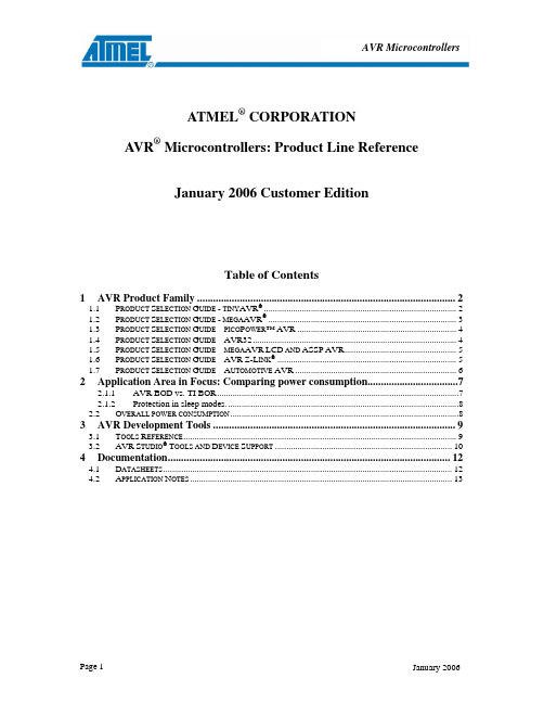
AVR MicrocontrollersATMEL® CORPORATIONA VR® Microcontrollers: Product Line ReferenceJanuary 2006 Customer EditionTable of Contents1AVR Product Family (2)1.1P RODUCT S ELECTION G UIDE - TINY AVR® (2)1.2P RODUCT S ELECTION G UIDE - MEGA AVR® (3)1.3P RODUCT S ELECTION G UIDE – PICO P OWER™AVR (4)1.4P RODUCT S ELECTION G UIDE –AVR32 (4)1.5P RODUCT S ELECTION G UIDE – MEGA AVR LCD AND ASSP AVR (5)1.6P RODUCT S ELECTION G UIDE –AVR Z-L INK® (5)1.7P RODUCT S ELECTION G UIDE –A UTOMOTIVE AVR (6)2Application Area in Focus: Comparing power consumption (7)2.1.1AVR BOD vs. TI BOR (7)2.1.2Protection in sleep modes (8)2.2O VERALL POWER CONSUMPTION (8)3AVR Development Tools (9)3.1T OOLS R EFERENCE (9)3.2AVR S TUDIO®T OOLS AND D EVICE S UPPORT (10)4Documentation (12)4.1D ATASHEETS (12)4.2A PPLICATION N OTES (13)2 Application Area in Focus: Comparing power consumptionWritten by: Andreas Eieland, Applications Engineer, System Solutions GroupFigure 1 Atmel picoPower technologyIt is a known fact that there are two main competitors in the ultra low power MCU market. Atmel with the picoPower megaAVRs and Texas Instruments (TI) with the MSP430F2xx series.Lately there has been debate among development engineers, which MCU is the lowest power consumer. In most cases these discussions are based on readouts from datasheets and not real world applications. When using the datasheets to compare parts it is paramount to compare apples to apples to get the numbers right.We will address this and other issues that are important when comparing AVRs to MSP430s in this article. 2.1.1 AVR BOD vs. TI BORMany compare the TI Brown-out reset (BOR) to the AVR Brown-out detect (BOD), based on this they claim that TI have lower power consumption. This is not correct. The TI BOR circuitry is comparable in functionality, power consumption, and protection level to the AVR Power-on-Reset circuitry. The TI BOR and the AVR POR are both considered being “Zero-Power”.To achieve the same level of protection as the AVR BOD, which is present on all picoPower megaAVRs, you have to use the TI Supply Voltage Supervisor (SVS). The SVS is not present on any parts in the ultra low power MSP430F2xx series. It is only available onlarger, more expensive MSP430s. Figure 2: the Atmel picoPower BOD response timeWhen enabled the TI SVS is active in all operating modes. The additional current consumed by the SVS is maximum 15 µA. Though the AVR sleeping BOD has a slightly higher maximum consumption of 20 µA in active mode, power is saved compared to the SVS and other traditional BODs byautomatically disabling the BOD during sleep mode. The BOD is automatically re-enabled when the controller wakes up from sleep mode and is active before the AVR executes any instructions. This approach provides superior protection with substantially less power drain as the majority of the time is normally spent in sleep mode in low power applications – not in active mode.2.1.2Protection in sleep modes.The accuracy of BODs is directly proportional to the current they consume. Low- or zero-power BODs tend to be both slow and inaccurate, while more accurate, faster BODs consume more power. Since BODs usually remain on in sleep mode, they represent a substantial drag on battery life. As a result, most vendors of ultra low power MCUs, sacrifice accuracy and speed to reduce current consumption.In some comparisons it is claimed that the sleeping BOD does not provide sufficient protection in sleep modes since the Brown out detector is turned off. This claim is based on the belief that one cannot predict when a brown out condition occurs. This is not true! In any battery powered system the voltage drops when the current consumption is high. The current consumption is high when the device is in active mode. If the battery voltage drops to below the BOD threshold while the part is in sleep mode, there will be no Flash or EEPROM corruption. The POR is active in all operating modes and will prevent the MCU from performing illegal or undefined operations inside the MCU and on the I/O pins. When the part wakes up, the BOD will trigger immediately if the voltage is to low. This ensures that no code is executed when the system behavior is undefined. With the sleeping BOD the picoPower controllers get the best of both worlds, very good protection while in active mode, and no power consumption penalty in sleep.2.2Overall power consumptionThere is no family of microcontrollers today that will have the lowest power consumption in all possible applications. Power consumption will always be dependent on the suitability of the MCU to the application. We do however claim that the AVR picoPower devices are the market leader in ultra low power technology, as it will give the lowest power consumption in the majority of applications.Comparing total power consumption for an application implemented with different controllers is a complex task. Things one has to take into consideration are energy consumed per instruction, amount of instructions needed to perform the operation, and how long time the application can stay in sleep. Depending on the level of system integration on the MCU, it might be necessary to add extra components to the design. The additional power consumption from these parts must also be added. The MSP430 BOR is an example of this. The BOR has a very slow response time and does not give sufficient protection in many high-speed systems. An external BOD is needed to ensure reliable operation, this adds to the total current consumption. The rule of thumb to reduce power consumption for all MCUs, when not considering external circuitry, is to stay in active mode for the shortest possible time, go to the deepest possible sleep-mode, and stay in the sleep mode for the longest possible time before waking up again. The time spent in active mode is very short for most low-power applications. Hence it is the power consumption in sleep that will make or break the power budget.Figure 3 Average power consumption exampleThe computational performances of the AVR and MSP430 cores are in the same range. For some applications the AVR is better, for other the MSP430 is better. As with power consumption there is no single part, or family of parts, that give the best performance for all applications. The MSP430 is a 16 bit MCU and will be better than the AVR in many applications that use 16 bit arithmetic’s, but the AVR uses fewer cycles in most other applications.AVR MCUs can run up to 25% faster than the MSP430F2xx series. In addition to this the picoPower megaAVRs has lower power consumption than TI in sleep modes and does not require an external BOD. Shorter time in active mode combined with lower power consumption in sleep gives the AVR picoPower devices lower overall power consumption than the MSP430F2xx in most ultra low power applications.Figure 4 Atmel AVR picoPower devicesFor more information about AVR picoPower see: /products/AVR/picopower/3A VR Development ToolsAtmel provides a complete range of development tools for the AVR products.3.1Tools ReferencePart Number DescriptionSoftwareAVR Studio 4.12 Front end software for AVR development toolsStarter KitsSTK500 AVR Starter Kit with AVR Studio InterfaceSTK501 Expansion of STK500 to support 64-pin megaAVR devicesSTK502 Expansion of STK500 for 64-pin LCD AVR devicesSTK503 Expansion of STK500 for 100-pin megaAVR devicesSTK504 Expansion of STK500 for 100-pin LCD AVR devicesSTK505 Expansion of STK500 for 14-pin SOIC and 20-pin PDIP AVR devicesSTK520 Expansion of STK500 for 90PWM devicesSTK525 Starter Kit for AT90USB devicesSTK1000 Starter Kit for AVR32AP7xxx devicesEvaluation Kits90EIT1 AVR Embedded Internet Tool KitAVRBFLY ATmega169 Demo Board with LCD and SpeakerAVRMC100 BLDC Motor Control with AT90PWM3AVRMC200 AC Induction Motor KitAVRMC201 Induction Motor for ATAVRMC200AVRFBKIT DALI Dimmable Fluorescent Ballast KitAVRRTOS AVR Real Time Operating System development kitPart Number Description90USBKEY AVR USB Key Demonstration KitAVRRZ200 Z-Link Demonstration KitAKSTK512-3 RemoteAccessControl – Unidirectional Kit 315 MHzAKSTK512-4 RemoteAccessControl – Unidirectional Kit 434 MHzDevelopment KitsDVK90CAN1 DVK90CAN1 Development Kit for AT90CAN devicesAVRSB100 Smart Battery Development Kit for Atmega406AVRISP2 ISP programmer for all AVR ISP devicesAVRRZ502 Z-Link RF Accessory KitAVRDRAGON Starterkit supporting On-Chip Debugging and programming for AVR. (AVR Dragon will support OCD for all AVRs with 32 kB or less Flash memory and programming for all AVRs. Sesection “AVR Studio Tools and Device Support” for current device support. More devicesupport will be available soon )EmulatorsICE50 AVR In-Circuit Emulator for all megaAVR and new tinyAVR devices.JTAGICE2 JTAGICE mkII On-Chip Debugger supporting all AVR and AVR32 with debugWIRE or JTAG interfaceJTAGPROBE JTAGICE mkII Probe including Flex CablesADAPTEST ICE50 Test AdapterADAPMEGA8 ICE50 Mega8 PDIP personality adapterADAPMEGA32 ICE50Mega8535/16/32PDIP personality adapterADAP128_TOP ICE50 Mega64/128 TQFP personality adapter (top module); requires one AT64PSKT_BOT as the bottom moduleADAP169_TOP ICE50 Mega169 TQFP personality adapter (top module); requires one AT64PSKT_BOT as the bottom moduleADAPMEGA162 ICE50 Mega8515/162 PDIP personality adapterADAPTINY26 ICE50 Tiny26 PDIP personality adapterADAPTINY13 ICE50 Tiny13 PDIP personality adapterADAPT2313 ICE50 Tiny2313 PDIP personality adapterATADAPCAN01 STK500/501 90CAN128 CAN adapterICE50MEM ICE50 memory extension card for mega2560/2561ICE50PROBE ICE40/50 Probe including Flex CablesICE50POD ICE40 and ICE50 POD replacement kit3.2AVR Studio® Tools and Device SupportAVR Studio 4.12 with the latest Service Pack supports all new Atmel debug platforms and devices. Some of the old devices are not supported. See below for a table of currently supported tools and devices in AVR Studio. This support is in progress, and the table below is not guaranteed to be complete when this is read. This information can also be found in the AVR Studio online help and on /avrThe latest AVR Studio SW can be found on: /dyn/products/tools_card.asp?tool_id=2725Device Simulator/AssemblerJTAGICEmkII Starter kitAVRDragonAVR ISPmkIIATtiny11 • STK500ATtiny12 • STK500 •ATtiny13 ••STK500 ••ATtiny15 • STK500 •ATtiny24 ••STK500 + STK505 •ATtiny25 ••STK500 ••ATtiny26 •STK500 (+ STK505) •Device Assembler mkII Starter kit Dragon mkII ATtiny261 ••STK500 (+ STK505) •ATtiny28 • STK500ATtiny44 ••STK500 + STK505 •ATtiny45 ••STK500 ••ATtiny461 ••STK500 (+ STK505) •ATtiny84 ••STK500 + STK505 •ATtiny85 ••STK500 ••ATtiny861 ••STK500 (+ STK505) •ATtiny2313 ••STK500 ••ATmega48 ••STK500 ••ATmega8 • STK500 •(Programmingonly)•ATmega88 ••STK500 ••ATmega8515 • STK500 •ATmega8535 • STK500 •ATmega16 ••STK500 ••ATmega162 ••STK500 •ATmega164P ••STK500 •ATmega165 ••STK500 + STK502 •ATmega165P ••STK500 + STK502 •ATmega168 ••STK500 ••ATmega169 ••STK500 + STK502 •ATmega169P ••STK500 + STK502 •ATmega32 ••STK500 ••ATmega324P ••STK500 •ATmega325 ••STK500 + STK502 •ATmega325P ••STK500 + STK502 ••ATmega3250 ••STK500 + STK504 •ATmega3250P ••STK500 + STK504 ••ATmega329 ••STK500 + STK502 •ATmega329P ••STK500 + STK502 ••ATmega3290 ••STK500 + STK504 •ATmega3290P ••STK500 + STK504 ••ATmega64 ••STK500 +STK501 •ATmega640 ••STK500 + STK503 •ATmega644 ••STK500 •ATmega644P ••STK500 •ATmega645 ••STK500 + STK502 •ATmega6450 ••STK500 + STK504 •ATmega649 ••STK500 + STK502 •ATmega6490 ••STK500 + STK504 •ATmega128 ••STK500 + STK501•(Programmingonly)•ATmega1280 ••STK500 + STK503 •ATmega1281 ••STK500 + STK501 •ATmega2560 ••STK500 + STK503 •ATmega2561 ••STK500 + STK501 •ATmega406 ••AT90CAN32 ••STK500 + STK501 +ATADAPCAN1•AT90CAN64 ••STK500 + STK501 +ATADAPCAN1•Device Assembler mkII Starter kit Dragon mkIIAT90CAN128 ••STK500 + STK501 +ATADAPCAN1•AT90PWM2 ••STK500 + STK520 •AT90PWM3 ••STK500 + STK520 •AT90USB646 ••STK500 + STK525 •AT90USB647 ••STK500 + STK525 •AT90USB1286 ••STK500 + STK525 •AT90USB1287 ••STK500 + STK525 •AT32AP7000 •STK1000AT32AP7001 •STK1000AT32AP7002 •STK10004DocumentationAll documents listed can be downloaded from Atmel Corporation’s web site: underthe product section. For other documentation, please send your request to avr@.4.1DatasheetsThe datasheets of all AVR devices can be downloaded.AVR: /dyn/products/datasheets.asp?family_id=607.AVR32: /dyn/products/datasheets.asp?family_id=682Family Devices LanguagePreliminary Summary Complete LastUpdate Auto AVR ATtiny25/45/85 Automotive English X X 09/2006 Auto AVR ATmega48/88/168 Automotive English X 09/2006 Auto AVR ATmega88 Automotive - 150°CSpecification - Appendix AEnglish X 09/2006 Auto AVR AT90CAN128 Automotive English X X 09/2006 CAN AVR AT90CAN32/64/128 English X X X 11/2006 CAN AVR AT90CAN128 English X X 05/2006 LCD AVR ATmega169(V English X X 07/2006 LCD AVR ATmega169(V) Chinese X X 9/04 LCD AVR ATmega329/3290/649/6490 English X X X 11/2006 USB AVR AT90USB1287/1286/646/647 English X X 02/06 Lighting AVR AT90PWM2, AT90PWM3 English X X 12/2006AVR Z-Link AT86RF230 ZigBee™/IEEE802.15.4-Transceiver English X X06/2006megaAVR ATmega48/88/168 EnglishXXX12/2006 megaAVR ATmega48/88/168 ChineseX X02/05 megaAVR ATmega8(L) English X X10/2006 megaAVR ATmega8(L) Chinese X7/04 megaAVR ATmega8515(L) English X X10/2006 megaAVR ATmega8515(L) Chinese X9/04 megaAVR ATmega8535(L) EnglishX X X10/2006 megaAVR ATmega8535(L) ChineseX X9/04 megaAVR ATmega16(L) English X X10/2006 megaAVR ATmega16(L) Chinese X10/04 megaAVR ATmega162(V) English X X 04/06 megaAVR Atmega164P/324P/644P EnglishX X X10/2006 megaAVR ATmega165(V) English X X X08/2006 megaAVR ATmega32(L) English X X10/2006 megaAVR ATmega32(L) ChineseX X09/04 megaAVR ATmega325/3250/645/6450 English X X X 11/2006Family Devices LanguagePreliminary Summary Complete LastUpdate megaAVR ATmega64(L) English X X10/2006 megaAVR ATmega64(L) ChineseX X09/04megaAVR ATmega640/1280/1281/2560/2561 English X X X09/2006megaAVR ATmega644 EnglishX X X09/2006 megaAVR ATmega128(L) English X X10/2006 megaAVR ATmega128(L) Chinese X05/04 picoPower megaAVR ATmega164P/324P/644P English X X X09/2006 picoPower megaAVR ATmega165P(V) EnglishXXX11/2006 picoPower megaAVR ATmega325P/3250P English X X X 12/2006picoPower LCD megaAVR ATmega169P(V) EnglishXXX11/2006picoPower LCD megaAVR ATmega329P/3290P EnglishXXX12/2006Smart Battery AVR ATmega406 English X X X 07/2006 tinyAVR ATtiny11/12 English XX07/2006 tinyAVR ATtiny13 EnglishXXX10/04 tinyAVR ATtiny13 ChineseX X04/04 tinyAVR ATtiny15L English XX06/05 tinyAVR ATtiny2313 EnglishXXX04/2006 tinyAVR ATtiny2313 ChineseX X07/04 tinyAVR ATtiny24/44/84 EnglishXXX09/2006 tinyAVR ATtiny25/45/85 EnglishXXX12/2006 tinyAVR ATtiny26(L) English XX10/2006 tinyAVR ATtiny26(L) ChineseX X12/03 tinyAVR ATtiny261/461/861 EnglishXXX11/2006 tinyAVR ATtiny28(L)(V) English XX07/2006USB AVR AT90USB1286, AT90USB1287,AT90USB646, AT90USB647 English X X07/2006USB AVR USB DFU Bootloader Datasheet English 04/06 AVR32 AT32AP7000 EnglishXXX10/2006 AVR32 AVR32 Architecture Manual English X X 02/06AVR32 AVR32 Technical ReferenceManual English X X06/2006AVR32 AVR32 Java Technical ReferenceManual English X X10/20064.2Application NotesThe application notes for all AVR devices can be downloaded.AVR: /dyn/products/app_notes.asp?family_id=607AVR32: /dyn/products/app_notes.asp?family_id=682Note Number Description Last Update AVR000 Register and Bit-Name Definitions for the AVR Microcontroller 4/98 AVR001 Conditional Assembly and Portability Macros 3/05 AVR030 Getting Started with IAR Embedded Workbench for Atmel AVR 10/04 AVR031 Getting Started with ImageCraft C for AVR 5/02 AVR032 Linker Command Files for the IAR ICCA90 Compiler 5/02 AVR033 Getting Started with the CodeVision AVR C Compiler 5/02 AVR034 Mixing C and Assembly Code with AVR Embedded Workbench for AVR 4/03 AVR035 Efficient C Coding for AVR 1/04 AVR040 EMC Design Considerations 06/2006 AVR042 AVR Hardware Design Considerations 06/2006 AVR053 Calibration of the Internal RC Oscillator 05/2006Note Number Description Last Update AVR054 Run-time calibration of the internal RC oscillator 02/2006 AVR055 Using a 32kHz XTAL for run-time calibration of the internal RC 02/2006 AVR060 JTAGICE 01/04 Protocol 4/03 AVR061 STK500AVR063 LCD Driver for the STK®504 04/2006 AVR064 STK502 – A Temperature Monitoring System with LCD Output 02/2006 AVR065 LCD Driver for the STK502 02/2006 AVR067 JTAGICE mkII Communication Protocol 04/2006 AVR068 STK500 Communication Protocol 06/2006 AVR069 AVRISP mkII Communication Protocol 02/2006 AVR070 Modifying AT90ICEPRO to Support Emulation of AT90 5/02 AVR072 Accessing 16-bit I/O Registers 5/02 AVR073 Accessing 10- and 16-bit registers in ATtiny261/461/86112/2006 AVR074 Upgrading AT90ICEPRO to ICE10 5/02 AVR080 ATmega103 Replaced by ATmega128 01/04 AVR081 ReplacingAT90S4433 by ATmega8 7/03ATmega161 by ATmega162 01/04 AVR082 ReplacingATmega163 by ATmega16 09/05 AVR083 ReplacingAVR084 ReplacingATmega323 by ATmega32 7/03AT90S8515 by ATmega8515 1/04 AVR085 ReplacingAVR086 ReplacingAT90S8535 by ATmega8535 7/03 AVR087 Migrating between ATmega8515 and ATmega162 7/03 AVR088 Migrating between ATmega8535 and ATmega16 1/04 AVR089 Migrating between ATmega16 and ATmega32 6/03 AVR090 Migrating between ATmega64 and ATmega128 6/03 AVR091 Replacing AT90S2313 by ATtiny2313 10/03 AVR092 Replacing ATtiny11/12 by ATtiny13 10/03 AVR093 Replacing AT90S1200 by ATtiny2313 10/03 ATmega8 by ATmega88 4/05 AVR094 ReplacingAVR095 Migrating between ATmega48, ATmega88 and ATmega168 2/04 AVR096 Migrating from ATmega128 to AT90CAN128 3/04 AVR097 Migration between Atmega128 and ATmega2561 07/2006 AVR098 Migration between ATmega169, ATmega329 and ATmega649 04/2006 AT90S4433 by ATmega48 07/04 AVR099 ReplacingEEPROM 09/05 AVR100 AccessingtheAVR101 High Endurance EEPROM Storage 9/02 AVR102 BlockRoutines 5/02 AVR103 Using the EEPROM Programming Modes 3/05 AVR104 Buffered Interrupt Controlled EEPROM Writes 7/03 AVR105 Power Efficient High Endurance Parameter Storage in Flash Memory 9/03 AVR106 C functions for reading and writing to Flash memory 08/2006 AVR107 Interfacing AVR serial memories 3/05 AVR108 Setup and Use of the LPM Instructions 5/02 AVR109 Self-programming 6/04 AVR120 Characterization and Calibration of the ADC on an AVR 02/2006 AVR121 Enhancing ADC resolution by oversampling 09/05 AVR128 Setup and Use the Analog Comparator 5/02 AVR130 Setup and use the AVR Timers 2/02 AVR131 Using the AVR’s High-speed PWM 9/03 AVR132 Using the Enhanced Watchdog Timer 11/03 AVR133 Long Delay Generation Using the AVR Microcontroller 2/04 AVR134 Real-Time Clock using the Asynchronous Timer 08/2006 AVR135 Using Timer Capture to Measure PWM Duty Cycle 10/2005 AVR136 Low-jitter Multi-channel Software PWM05/06 AVR137 Writing Software Compatible for AT90PWM2/3 and AT90PWM2B/3B12/2006family run-time calibration of the Internal RC oscillator09/2006 AVR140 ATmega48/88/168Note Number Description Last Update AVR151 Setup and use of the SPI 09/05 AVR155 Accessing I2C LCD Display Using the AVR 2-Wire Serial Interface 09/05 AVR180 External Brown-Out Protection 5/02 AVR182 Zero Cross Detector 1/04 AVR191 Anti-Pinch Algorithm for AVR Adaptation Procedure11/2006 AVR200 Multiply and Divide Routines 05/2006 AVR201 Using the AVR Hardware Multiplier 6/02 Arithmetic 5/02 AVR202 16-BitArithmetic 1/03 AVR204 BCDAVR220 BubbleSort 5/02 AVR221 Discrete PID controller 05/2006 AVR222 8-Point Moving Average Filter 5/02 AVR223 Digital Filters with AVR 9/02 Bootloader 4/05 AVR230 DESBootloader 08/2006 AVR231 AESAVR236 CRC Check of Program Memory 5/02 AVR240 4x4 Keypad-Wake Up on Keypress 06/2006 AVR241 Direct driving of LCD display using general I/O 5/04 AVR242 8-bit Microcontroller Multiplexing LED Drive & a 4x4 Keypad 5/02 AVR243 Matrix Keyboard Decoder 1/03 AVR244 UART as ANSI Terminal Interface 11/03 AVR245 Code Lock with 4x4 Keypad and I2C™ LCD 10/2005 AVR270 USB Mouse Demonstration 02/2006Demonstration 02/2006 KeyboardAVR271 USBAVR272 USB CDC Demonstration UART to USB Bridge 04/2006 AVR273 USB Mass Storage Implementation 04/2006 AVR301 C Code for Interfacing AVR® to AT17CXX FPGA Configuration Memory 1/04Gateway 3/05 AVR303 SPI-UARTAVR304 Half Duplex Interrupt Driven Software UART 8/97 AVR305 Half Duplex Compact Software UART 09/05 AVR306 Using the AVR UART in C 7/02 AVR307 Half Duplex UART Using the USI Module 10/03 AVR308 Software LIN Slave 5/02 AVR309 Software Universal Serial Bus (USB) 02/2006 AVR310 Using the USI Module as a I2C Master 9/04 AVR311 Using the TWI Module as a I2C Slave 10/04 AVR312 Using the USI Module as a I2C Slave 09/05 AVR313 Interfacing the PCAT Keyboard 09/05 AVR314 DTMFGenerator 5/02 AVR315 Using the TWI Module as a I2C Master 10/04 AVR316 SMBus Slave Using the TWI Module 10/2005 AVR317 Using the USART on the ATmega48/88/168 as a SPI master 11/04 AVR318 Dallas 1-Wire® Master 10/04 AVR319 Using the USI module for SPI communication 11/04 AVR320 Software SPI Master 09/05 AVR322 LIN v1.3 Protocol Implementation on Atmel AVR Microcontrollers 12/05 AVR323 Interfacing GSM modems02/2006 AVR325 High-Speed Interface to Host EPP Parallel Port 2/02 AVR328 USB Generic HID Implementation 1/06 AVR329 USB Firmware Architecture 02/2006 AVR335 Digital Sound Recorder with AVR and Serial Data Flash 4/05 AVR336 ADPCMDecoder 1/05Utility for AVR 09/05ReceiveAVR350 XmodemCRCAVR360 Step Motor Controller 4/03 AVR400 Low Cost A/D Converter 5/02 AVR401 8-Bit Precision A/D Converter 2/03Note Number Description Last Update AVR410 RC5 IR Remote Control Receiver 5/02 AVR411 Secure Rolling Code Algorithm for Wireless Link04/06 AVR414 User Guide - ATAVRRZ502 - Accessory Kit12/2006 AVR415 RC5 IR Remote Control Transmitter 5/03 AVR433 Power Factor Corrector (PFC) with AT90PWM2 Re-triggable High Speed PSC 03/2006 AVR434 PSC Cookbook 10/2006 AVR435 BLDC/BLAC Motor Control Using a Sinus Modulated PWM Algorithm 09/2006 AVR440 Sensorless Control of Two-Phase Brushless DC Motor 09/05 AVR441 Intelligent BLDC Fan Controller with Temperature Sensor and Serial Interface 9/05 AVR442 PC Fan Control using ATtiny13 9/05 AVR443 Sensor-based control of three phase Brushless DC motor 02/2006 AVR444 Sensorless control of 3-phase brushless DC motors 10/2005 AVR446 Linear speed control of stepper motor06/200606/2006 AVR447 Sinusoidal driving of three-phase permanent magnet motor usingATmega48/88/168AVR448 Control of High Voltage 3-Phase BLDC Motro 05/2006 AVR449 Sinusoidal driving of 3-phase permanent magnet motor using ATtiny261/461/86110/2006 AVR450 Battery Charger for SLA, NiCd, NiMH and Li-ion Batteries 09/2006 AVR452 Sensor-based Control of Three Phase Brushless DC Motors Using CAN128 64 3203/2006 or mega128 64 usiAVR453 Smart Battery Reference Design 02/2006 AVR454 Users Guide – ATAVRSB100 – Smart Battery Development Board 06/2006Server 5/02 WebAVR460 EmbeddedAVR461 Quick Start Guide for the Embedded Internet Toolkit 5/02 AVR462 Reducing the Power Consumption of ATEIT1 3/02 meter 7/04 AVR465 EnergyAVR480 Anti-Pinch System for Electrical Window 12/2006 AVR492 Brushless DC Motor Control using AT90PWM3 7/0507/2006 AVR493 Sensorless Commutation of Brushless DC Motor (BLDC) using AT90PWM3 andATAVRMC10012/05 AVR494 AC Induction Motor Control Using the constant V/f Principle and a Natural PWMAlgorithm02/2006 AVR495 AC Induction Motor Control Using the Constant V/f Principle and a Space-vectorPWM AlgorithmAVR500 Migration between Atmega64 and Atmega645 9/04 AVR501 Replacing ATtiny15 with ATtiny25 3/05 AVR502 Migration between Atmega165 and ATmega325 11/04 AVR503 Replacing AT90S/LS2323 or AT90S/LS2343 with ATtiny25 09/05 AVR504 Migrating from ATtiny26 to ATtiny261/461/861 10/2006 AVR505 Migration between Atmega16/32 and ATmega164/324/644 06/2006Atmega169 to ATmega169P 06/2006 AVR506 MigrationfromAVR507 Migration from ATmega329 to ATmega329P 11/2006ATmega644 to ATmega644P 07/2006 AVR508 MigrationfromAVR509 Migration between ATmega169P and ATmega329P 11/2006 AVR510 Migration between ATmega329/649 and ATmega3290/649007/2006 AVR511 Migration from ATmega3290 to ATmega3290P11/2006 AVR910 In-SystemProgramming 11/00 AVR911 AVR Open-source Programmer 7/0405/2006 AVR914 CAN & UART based Bootloader for AT90CAN32, AT90CAN64, &AT90CAN128AVR32000Introduction to AVR32 header files05/2006 AVR32100 Using the AVR32 USART 4/06 AVR32101 Configuring the AVR32 Interrupt Controller 4/06 AVR32102Using the AVR32 SDRAM Controller05/2006 AVR32105Master and Slave SPI Driver05/2006 AVR32107 Using TWI as a master on the AVR32 4/06Note Number Description Last Update AVR32108Peripheral Direct Memory Access Driver05/2006 AVR32110Using the AVR32 Timer/Counter05/2006 AVR32111Using the AVR32 PIO Controller05/2006 AVR32113Configuration and Use of the Memory Management Unit09/2006© 2007 Atmel Corporation. All Rights Reserved. Atmel®, logo and combinations thereof, Everywhere You Are®,AVR® , Z-Link® and others,are registered trademarks, picoPower™ and others are trademarks of Atmel Corporation or its subsidiaries. Other terms and product names may be trademarks of others.。
Shure SM7dB 电子预制头耳机用户指南说明书

SM7dBVocal Microphone with Active PreampSM7dB online user guide.Version: 2.0 (2023-I)Table of ContentsSM7dB Vocal Microphone with Active Preamp3 SAFETY PRECAUTIONS3 General Description3 Powering the SM7dB Preamplifier 3 Preamplifier Best Practices 3 Using Variable Impedance Mic Preamplifiers4 Microphone Placement4 Windscreen 5Adjust Back Panel Switches5 Switching Microphone Orientation 6 Install or Remove the Stand Adapter 7 Specifications8 Accessories 11 Furnished Accessories11 Replacement Parts 11 Certifications 11SM7dBVocal Microphone with Active PreampSAFETY PRECAUTIONSBefore using this product, please read and save the enclosed warnings and safety instructions.WARNING: Ignoring these warnings may cause severe injury or death as a result of incorrect operation.If water or other foreign objects enter the inside of the device, fire or electric shock may result.Do not attempt to modify this product. Doing so could result in personal injury and/or product failure.CAUTION: Ignoring these cautions may cause moderate injury or property damage as a result of incorrect operation.Never disassemble or modify the device, as failures may result.Do not subject to extreme force and do not pull on the cable or failures may result.Keep the microphone dry and avoid exposure to extreme temperatures and humidity.General DescriptionThe Shure SM7dB dynamic microphone has a smooth, flat, wide-range frequency response appropriate for content creation, speech, music, and beyond. A builtin active preamplifier provides up to +28 dB of lownoise, flat, transparent gain while preserving frequency response for a clean, classic sound. The SM7dB's built-in preamp delivers the legendary sound of theSM7B, completely uncompromised and without the need for an inline preamplifier. The SM7dB back panel switches allow customized frequency response and the ability to adjust or bypass the preamp.Powering the SM7dB PreamplifierImportant: The SM7dB requires +48 V phantom power to operate with the preamplifier engaged. It will operate in bypass mode without phantom power.To deliver audio directly to a computer, use an audio interface with an XLR input that provides +48 V phantom power, such as the Shure MVi or MVX2U, and turn phantom power on.When connecting to a mixer, use only balanced, microphone-level inputs with phantom power. Turn phantom power on for the channel your SM7dB is connected to.Depending on your interface or mixer, phantom power may be enabled through a switch, a button, or control software. Refer to the user guide for your interface or mixer to learn how to engage phantom power.Preamplifier Best PracticesThe SM7dB features a builtin active preamplifier which provides up to +28 dB of lownoise, flat, transparent gain that optimizes audio performance.Adjust the gain level on the SM7dB before adjusting levels on your interface or mixer. This approach maximizes the signal-to-noise ratio for a cleaner, clearer sound.In podcast or quiet vocal applications, you are more likely to need the +28 dB setting, while louder talkers or singers may only need the +18 dB setting. For instrumental applications, you may find that the +18 dB or the bypass settings reach the ideal input levels.Using Variable Impedance Mic PreamplifiersSelect the highest available impedance setting on the external preamp when using the built-in preamp.If you are using a low impedance setting to change the tonality for creative purposes, bypass the SM7dB's built-in preamp. Keeping the SM7dB preamp engaged with a low-impedance setting will not yield the same changes in tone.Microphone PlacementSpeak directly into the mic, 1 to 6 inches (2.54 to 15 cm) away to block offaxis noise. For a warmer bass response, move closer to the microphone. For less bass, move the microphone away from you.Velcro Cable TieUse the enclosed velcro tie to secure the cable.WindscreenUse the standard windscreen for general voice and instrumental applications.When you speak, you may hear vocal pops from some consonant sounds (known as plosives). To prevent more plosive sounds and wind noise, you can use the larger A7WS windscreen.Adjust Back Panel Switches1.2.3.4.5.6.7.① Bass Rolloff Switch To reduce the bass, push the top-left switch down. This can help lower background hum from A/C, HVAC, or traffic.② Presence Boost For a brighter sound in mid-range frequencies, push the top-right switch up. This can help improve vocal clarity.③ Bypass Switch Push the bottom-left switch to the left to bypass the preamp and achieve the classic SM7B sound.④ Preamp Switch To adjust the gain on the built-in preamp, push the bottom-right switch to the left for +18 dB and to the right for +28 dB.Switching Microphone OrientationBoom and Microphone Stand Mounting ConfigurationThe SM7dB can be mounted on a boom arm or a stand. The default setup for the SM7dB is for a boom mount. To keep the rear panel facing upright when mounted on a stand, reconfigure the mounting assembly.To set up the SM7dB for a microphone stand:Remove tightening nuts on the sides.Remove the fitted washers, the lock washers, the outer brass washers, and the brass sleeves.Slide the bracket off the microphone. Be careful not to lose the washers still on the microphone.Invert and rotate the bracket. Slide it back onto the bolts over the brass and plastic washers still on the microphone. The bracket should fit so the XLR connector faces the rear of the microphone and the Shure logo on the back of the microphone is right-side up.Replace the brass sleeves. Be sure they are seated properly within the inner washers.Replace the outer brass washers, the lock washers, and the fitted washers.Replace the tightening nuts and tighten the microphone at the desired angle.Note: If the tightening nuts do not hold the microphone in place, you may need to re-position the brass sleeves and the washers.Mounting Assembly - Exploded View① Tightening nut② Fitted washer③ Lock washer④ Brass washers⑤ Brass sleeve⑥ Mounting bracket⑦ Plastic washer⑧ Response switches⑨ Switch cover⑩ WindscreenInstall or Remove the Stand AdapterTo mount the microphone on a 3/8 in. stand, insert the included brass stand adapter and tighten it with a coin or screwdriver.Important: Make sure that the slots on the adapter face outward.SpecificationsTypeDynamic (moving coil)Frequency Response50 to 20,000 HzPolar PatternCardioidOutput ImpedancePreamp engaged27 ΩBypass mode150 ΩRecommended Load>1k ΩSensitivityFlat response bypass mode59 dBV/Pa[1] (1.12 mV)Flat response +18 preamp engaged-41 dBV/Pa[1] (8.91 mV)Flat response +28 preamp engaged-31 dBV/Pa[1] (28.2 mV)Hum Pickup(typical, at 60 Hz, equivalent SPL/mOe)11 dBPreamplifier Equivalent Input Noise(A-weighted, typical)-130 dBVPolarityPositive pressure on diaphragm produces positive voltage on pin 2 with respect to pin 3Power Requirements(with preamp engaged)48 V DC [2] phantom power (IEC-61938) 4.5 mA, maximumWeight0.837 kg (1.875 lbs)HousingBlack enamel aluminum and steel case with black foam windscreen[1] 1 Pa=94 dB SPL[2]All specifications measured with a 48 Vdc phantom power supply. The microphone operates at lower voltages, but with slightly decreased headroom and sensitivity.Typical Frequency ResponseTypical Polar PatternOverall DimensionsAccessoriesFurnished AccessoriesBlack Foam Windscreen RK345BLarge Black Foam Windscreen for SM7, also see RK345A7WS5/8" to 3/8" Thread Adapter31A1856Replacement PartsCartridge for SM7dB RPM106BBlack Windscreen for SM7dB RK345BNut and Washers for SM7dB Yoke Mount RPM604BCertificationsCE NoticeHereby, Shure Incorporated declares that this product with CE Marking has been determined to be in compliance with European Union requirements.The full text of the EU declaration of conformity is available at the following site: https:///enEU/support/declarations-of-conformity.UKCA NoticeHereby, Shure Incorporated declares that this product with UKCA Marking has been determined to be in compliance with UKCA requirements.The full text of the UK declaration of conformity is available at the following site: https:///enGB/support/declarations-of-conformity.Waste Electrical and Electronic Equipment (WEEE) DirectiveIn the European Union and the United Kingdom, this label indicates that this product should not be disposed of with household waste. It should be deposited at an appropriate facility to enable recovery and recycling.Please consider the environment, electric products and packaging are part of regional recycling schemes and do not belong to regular household waste.Registration, Evaluation, Authorization of Chemicals (REACH) DirectiveREACH (Registration, Evaluation, Authorization of Chemicals) is the European Union (EU) and the United Kingdom (UK) chemical substances regulatory framework. Information on substances of very high concern contained in Shure products in a concentration above 0.1% weight over weight (w/w) is available upon request.。
Valspar产品性能指南.pdf_1705921332.6793647说明书

The data on this sheet represent typical values. Since application variables are a major factor in product performance, this information should serve only as a general guide. Valspar assumes no obligation or liability for use of this information . UNLESS VALSPARAGREES OTHERWISE IN WRITING, VALSPAR MAKES NO WARRANTIES, EXPRESS OR IMPLIED, AND DISCLAIMS ALL IMPLIED WARRANTIES INCLUDING WARRANTIES OF MERCHANTABILITY OR FITNESS FOR A PARTICULAR USE ORDate: August 1, 2010(supersedes all previous revisions)Graintone Plus™ Universal Dye Concentrates-HAPs Free TECHNICAL DATA SHEETPHYSICAL PROPERTIES (objective specifications) VDS1051-Red VDS1054-OrangeVDS1052-Yellow VDS1056-BrownVDS1053-Black Viscosity: Weight Solids: Volume Solids: Weight/Gallon: Theoretical Coverage: Flash Point: Air Quality Information: VOC: AIM VOC: VOC Ratio VHAP: Photochemically Reactive?: N/A 26.0-35.7% 15.5-27.50%8.6-9.2 1bs/galN/A88-110ºF Closed Cup5.82-6.41lbs/gal or 695.5-766g/lN/A1.8-2.81lb VOC/lb solid0.0lb VHAP/lb solidNo Valspar’s GRAINTONE Plus™ Universal Dye Concentrates are concentrated dye colorants used to tint both solvent and waterborne stain bases, sealers and topcoats. These universal dye colorants allow the user to create stains and specialty coatings in both solvent and waterborne products with superior transparency, clarity and depth of color. They are typically used to make NGR (Non-Grain Raising) stains which are used as a first step in a multi-step system. They can also be added to washcoats, sealers, and topcoats to make transparent toners/shaders. These universal dye concentrates are for tinting purposes only and are notdesigned to be used directly on wood without first adding toan approved stain or coating. This product is designed forprofessional application only. For Wood Substrates Only.OTHER INFORMATION •Use in both solvent and waterborne products •Won’t fade like most dyes •Outstanding clarity •Make custom toners and shaders •Add depth of color without obscuring the wood grain.•Unlimited color options through custom tinting • HAPs Fre Dry Times (78°F, 50%RH): Air Dry To Touch/Handle: N/A To Sand/Recoat: N/A To Stack: Force Dry To Flash: N/ATo Bake: N/ACool Down: N/ATo Stack:Shelf life: 18 months unopened. These dye concentrates willincrease in color strength if not properly sealed immediatelyafter use.Application Equipment:N/ARecommended Tip Sizes:N/ANote: All information provided is typical (as formulated) andwill not represent exact values for every product. For specificAir Quality Data for each product, VOC reports are availableupon request.*As allowable within regulatory compliance requirements YYT0013 YYT1009 VWS0680 Zenith™ waterborne clear stain bases All Valspar Wood Finishes solvent based clear sealers and topcoats These products are recommended for professional application and are designed for interior use only. Always pre-test the system on your substrate and under your line conditions to verify suitability to the application and to avoid potential need for costly refinishing. Valspar Wood Finishes products are designed to protect and enhance the natural beauty of wood, but cannot eliminate natural discoloration or deterioration of wood as it ages.Additional notes:Do not mix with other finishing systems or deviate fromthese finishing recommendations. Valspar will not be heldliable for finish failures resulting from the mixing ofproducts or deviations from finishing recommendations.FINISHING RECOMMENDATIONSGeneral: Surface must be clean and dust free with moisture content of 6-8% prior to finishing. Remove all dirt, dust, wax and wood marks. Proper sanding and preparation of the wood is critical to achieving consistent results. New Wood: Finish sand surface (150-180 grit) and remove all sanding dust.Painted or Varnished Wood: Remove all paint or varnish then follow new wood instructions.Before using, mix product by hand, or use mechanical agitation such as an air mixer until there is no material on the bottom of the container. All products should be stirred well before use and, for best results, continuously agitated while in use.General: Always pre-test the system on your substrate to verify suitability of the application.These dye concentrates are used to tint approved solvent, and water based Valspar Wood Finishes stain bases, sealers, and topcoats (see companion products section of this document).Maximum recommended tint strength:When tinting as a NGR stain:YYT0013,YYT1009-10% by weightLWS2700-10% by weightWhen adding to a wiping stain to add color depth and dimension-LWS1000, LWS0750,VWS0680-10% by weight When adding to a solvent based washcoat, sealer, or topcoat- 1-5% by weightNOTE: These dye concentrates are NOT compatible with VWS0909, VWS055X, or VWS025X series stains or bases.Drying Time:Dry to touch: Refer to the Technical Data Sheet for the Product you are tintingDry to sand and recoat: Refer to the Technical Data Sheet for the Product you are tintingDo not apply if the material or substrate temperature is below 55ºF.This product is best applied when surface and air temperatures are between 55º-90º F (~12-32°C) and when relative humidity is below 50% during application and drying time.Refer to your local regulations for compliance requirements for cleaning solvents. Dispose of dirty solvent and cleaning rags in a safe and compliant manner. Solvent or lacquer soaked rags should be stored in water-filled, closed containers prior to disposal.Store in a cool, dry place. Close all containers after use. Do not store near heat or sparks. Spills should be cleaned up with non-sparking tools. See the product MSDS for complete safety information.Always pre-test the system on your substrate and under your line conditions to verify suitability to the application and avoid potential need for costly refinishing. All dry times listed are as tested under ideal indoor environmental conditions of 78°F (26°C) with relative humidity not exceeding 50%. These products are recommended for use under temperature conditions of 55º-90º F (~12-32°C)and when relative humidity is below 50% during application and drying time. Low temperatures, poor air circulation or high humidity will extend dry times. Valspar strongly recommends against use of these products if temperatures of air, material, or surface to be coated are below 55°F (12°C) or below the dew point. Abnormal conditions of temperature or humidity may adversely affect product performance. Please contact your authorized Valspar Wood Finishes distributor for additional product use recommendations and finishing guidance.The data on this sheet represent typical values. Since application variables are a major factor in product performance, this information should serve only as a general guide. Valspar assumes no obligation or liability for use of this information. UNLESS VALSPARAGREES OTHERWISE IN WRITING, VALSPAR MAKES NO WARRANTIES, EXPRESS OR IMPLIED, AND DISCLAIMS ALLIMPLIED WARRANTIES INCLUDING WARRANTIES OF MERCHANTABILITY OR FITNESS FOR A PARTICULAR USE OR。
DAC选型手册
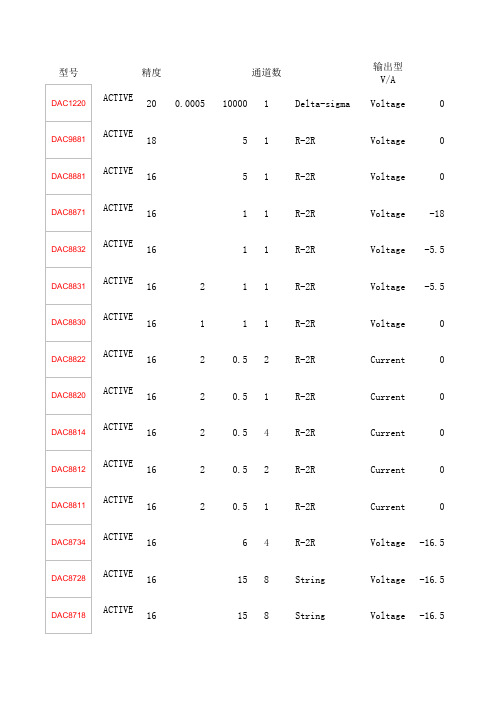
精度通道数输出型V/A200.0005100001 Delta-sigma Voltage 018 51 R-2R Voltage 016 51 R-2R Voltage 016 11 R-2R Voltage -1816 11 R-2R Voltage -5.516211 R-2R Voltage -5.516111 R-2R Voltage 01620.52 R-2R Current 01620.51 R-2R Current 01620.54 R-2R Current 01620.52 R-2R Current 01620.51 R-2R Current 016 64 R-2R Voltage -16.516 158 String Voltage -16.516 158 String Voltage -16.51630.651 String Voltage -5.516160.651 String Voltage -6160.043104 String Voltage -6160.043101 String Voltage 016 58 String Voltage 0160.284 String Voltage 0160.284 String Voltage 0 DAC856216 72 String Voltage 0160.281 String Voltage 0160.2104 String Voltage 0160.2104 String Voltage 0160.2102 String Voltage 0160.2101 String Voltage 0160.2101 String Voltage 016 84 String Voltage 0160.1101 String Voltage 0160.093104 String Voltage 0160.093102 String Voltage 0160.093101 String Voltage 0160.093101 String Voltage 016 61 String Voltage 0160.1104 R-2R Voltage -10160.251 R-2R Voltage -10160.251 R-2R Voltage -10160.089104 R-2R Voltage -10160.17251 R-2R Voltage -10160.1124 R-2R Voltage -2.5160.1124 R-2R Voltage -2.5160.1104 R-2R Voltage -2.5160.1102 R-2R Voltage -2.5160.1101 R-2R Voltage -2.5160.089104 R-2R Voltage -2.5160.089102 R-2R Voltage -2.5160.093101 R-2R Voltage -2.5160.086101 R-2R Voltage 0160.1101 R-2R Voltage 0160.086101 R-2R Voltage -10160.1101 R-2R Voltage -10168000.0112 Current sink Current 2168000.0112 Current sink Current 2165000.0122 Current sink Current 2165000.0122 Current sink Current 21610000.01042 Current sink Current 21610000.01041 Current sink Current 21610000.01041 Current sink Current 2168000.01042 Current sink Current 2166250.01042 Current sink Current 2160.000520001 Delta-sigma Voltage 0141250.0351 Current source Current 2142000.031 Current source Current 21420.51 R-2R Current 01420.52 R-2R Current 01420.54 R-2R Current 01420.52 R-2R Current 01420.51 R-2R Current 014 61 String Voltage 014 64 R-2R Voltage -16.514 158 String Voltage -16.514 158 String Voltage -16.514 58 String Voltage 014 84 String Voltage 014 84 String Voltage 0DAC816214 72 String Voltage 0144000.021 Current source Current 2142750.022 Current source Current 2142750.022 Current source Current 2142400 Current sink Current120.28611 String Voltage 0120.23312 String Voltage 0120.23311 String Voltage 0120.28611 String Voltage 0120.28318 String Voltage 012111 String Voltage 0120.10231 String Voltage 0120.10234 String Voltage 0120.102 4 String Voltage 0120.10234 String Voltage 0120.28611 String Voltage 0120.28318 String Voltage 0120.28318 String Voltage 0120.28318 String Voltage 0120.075 2.52 String Voltage 0121250.0351 Current source Current 2126661 R Ladder Voltage 0.78122000.031 Current source Current 2120.16741 R-2R Voltage -10120.2541 R-2R Voltage -10120.28411 R-2R Current 012100.22 R-2R Current 012100.21 R-2R Current 01250.21 R-2R Current 012 1.250.82 R-2R Current 012 1.250.82 R-2R Current 012 1.250.82 R-2R Current 012 158 String Voltage -16.5120.1104 R-2R Voltage -10120.1104 R-2R Voltage -1012 158 String Voltage -16.512 64 R-2R Voltage -16120.089104 R-2R Voltage -10120.089104 R-2R Voltage -10 ACTIVE 12 78 String Voltage 0 120.1104 R-2R Voltage -10120.1104 R-2R Voltage -2.5120.143101 R-2R Voltage -2.5120.089104 R-2R Voltage 0120.089104 R-2R Voltage 0120.089104 R-2R Voltage 0120.089104 R-2R Voltage -2.5120.1101 R-2R Voltage -2.5120.13102 R-2R Voltage -2.5120.132101 R-2R Voltage 0ACTIVE 12 78 String Voltage 0 120.043104 String Voltage 0120.043104 String Voltage 0120.05101 String Voltage 012 58 String Voltage 012 84 String Voltage 012 84 String Voltage 0 DAC756212 72 String Voltage 0120.558 String Voltage 012 54 String Voltage 012152 String Voltage 012152 String Voltage 0120.551 String Voltage 0120.095101 String Voltage 0120.095101 String Voltage 012 152 String Voltage -512 152 String Voltage -512 61 String Voltage 0122750.022 Current source Current 0122750.022 Current source Current 212400.0252 Current source Current 0.5100.2780.82 String Voltage 0100.28318 String Voltage 0100.093 2.52 String Voltage 0100.28318 String Voltage 0100.10231 String Voltage 0100.10234 String Voltage 0100.07512.51 String Voltage 0101250.0351 Current source Current 2102000.031 Current source Current 2102000.031 Current source Current 2 ACTIVE 10 78 String Voltage 0 100.18894 String Voltage 0100.18894 String Voltage 010 91 String Voltage 010 152 String Voltage -510 152 String Voltage -510 61 String Voltage 0102750.022 Current source Current 2102750.022 Current source Current 280.28318 String Voltage 080.28318 String Voltage 080.045108 String Voltage 080.107 2.54 String Voltage 080.2780.82 String Voltage 080.09332 String Voltage 080.23311 String Voltage 080.10231 String Voltage 080.008104 R-2R Voltage 080.048104 R-2R Voltage 08100.12 R-2R Current -108100.12 R-2R Current -108100.11 R-2R Current -1080.14354 R-2R Voltage -580.14354 R-2R Voltage -580.045108 String Voltage 080.048104 String Voltage 08300.031 I-steering Voltage 081000.0351 Current source Current 282000.031 Current source Current 2 ACTIVE 8 78 String Voltage 080.18884 String Voltage 080.18884 String Voltage 08 81 String Voltage 08 152 String Voltage -58 61 String Voltage 08 61 String Voltage 0ACTIVE 0.2561001 I-steering Current输入方式基准源E/I5.5 Serial SPI 1120 2.5 Ext 4.75 5.5 Serial SPI 1218 6 Ext 1.7 5.5 Serial SPI 1116 6 Ext 2.7 18 Serial SPI 1116 0.015 Ext 2.7 5.5 Serial SPI 1116 0.015 Ext 2.7 5.5 Serial SPI 1116 0.015 Ext 2.7 5.5 Serial SPI 1116 0.015 Ext 2.72 Parallel 1116 0.025 Ext 2.72 Parallel 1116 0.025 Ext 2.72 Serial SPI 1116 0.0275 Ext 2.72 Serial SPI 1116 0.025 Ext 2.72 Serial SPI 1116 0.025 Ext 2.7 16.5 Serial SPI 1116 280 Ext 2.7 33 Parallel 1416 107 Ext 2.7 33 Serial SPI 1416 115 Ext 2.75.5 Serial SPI 0.56416115100175 Ext 1.86 Serial SPI 16416115100175 Ext 1.86 Serial I2C 16416 2.7 Ext 2.7 5.5 Serial I2C 16516 0.42 Ext 2.7 5.5 Serial SPI 112168363 2.2 Int/Ext 2.7 5.5 Serial SPI 18168879 3.1 Int/Ext 1.8 5.5 Serial SPI 18168879 3.1 Int/Ext 1.85 Serial SPI 11216 0.5 Int/Ext5.5 Serial SPI 18168879 2.6 Int/Ext 2.7 5.5 Serial SPI 1121695873 Ext 1.8 5.5 Serial SPI 1121695873 Ext 1.8 5.5 Serial SPI 181695873 Ext 2.7 5.5 Serial SPI 1816 1 Ext 2.7 5.5 Serial SPI 181695871 Ext 2.7 5.5 Parallel 16516 4.75 Ext 1.8 5.5 Parallel 16516 0.72 Ext 1.8 5.5 Serial SPI 164169469 2.7 Ext 2.7 5.5 Serial SPI 165169469 1.35 Ext 2.7 5.5 Serial SPI 16416 0.72 Ext 2.7 5.5 Serial SPI 16416 0.72 Ext 2.7 5.5 Serial SPI 281588660.14 Ext 1.8 10 Parallel 1216 50 Ext 4.75 10 Parallel 1316 100 Int/Ext 4.75 10 Parallel 1316 100 Int/Ext 4.75 10 Serial SPI 2216 50 Ext 4.75 10 Serial SPI 3316 100 Int/Ext 4.75 2.5 Parallel 3316 18 Int/Ext 5.25 2.5 Serial SPI 1316 18 Int/Ext 4.75 2.5 Parallel 2315 7.5 Ext 4.75 2.5 Parallel 2315 2.5 Ext 4.752.5 Parallel 2315 2.5 Ext 4.752.5 Parallel 2315 1.8 Ext 4.752.5 Serial SPI 2315 7.5 Ext 4.752.5 Serial SPI 2315 2.5 Ext 4.752.5 Serial SPI 2315 1.8 Ext 4.7510 Serial SPI 2215 525 Int 4.510 Parallel 1216 525 Int 4.510 Serial SPI 1116 525 Int 4.510 Parallel 1215 525 Int 4.520 Parallel 24 79801750 Int 1.7120 Parallel 24 79801750 Int 1.7120 Parallel 36 75801410 Int 1.7120 Parallel 912 7272445 Int 1.6520 Parallel LVDS 24 79811300 Int 1.7120 Parallel LVDS 24 7981800 Int 1.7120 Parallel LVDS 24 7981650 Int 1.7120 8 Byte Wide LVDS 24 77831150 Int 1.7120 8 Byte Wide LVDS 24 7783950 Int 1.712.8 Serial SPI 1216 1.2 Ext 2.720 Parallel 3.57 75175 Ext 320 Parallel 2.53 76170 Int/Ext 2.72 Parallel 1114 0.025 Ext 2.72 Parallel 1114 0.025 Ext 2.72 Serial SPI 1114 0.0275 Ext 2.72 Serial SPI 1114 0.025 Ext 2.72 Serial SPI 0.5114 0.025 Ext 2.75.5 Serial SPI 141488660.14 Ext 1.8 16.5 Serial SPI 1114 260 2.733 Parallel 1214 107 2.733 Serial SPI 1214 115 Ext 2.755.5 Serial SPI 0.54148363 2.2 Int/Ext 2.75.5 Serial SPI 12148779 2.9 Int/Ext 1.85.5 Serial SPI 12148779 2.9 Int/Ext 1.85 Serial SPI 0.5314 0.5 Int/Ext5.5 Parallel LVDS 24 74660 Int 3.1520 Parallel 2 3.5 7176435 Int 1.6520 Parallel 34 7784330 Int 320 Parallel 34147784330 Int 3 Parallel LVDS 1.757.5 2000 Int5.1 Parallel 0.53127874 2.7 Int/Ext 2.75.1 Serial SPI 14127472 4.5 Int/Ext 2.75.1 Serial SPI 14127579 4.5 Int/Ext 2.75.1 Parallel 0.53127874 2.7 Int/Ext 2.75.1 Serial SPI 1612 18 Int/Ext 2.75.1 Parallel 14127872 4.3 Ext 2.75.1 Serial SPI 14127672 1.8 Ext 2.7 5.1 Serial SPI 141274700.9 Ext 2.7 5.1 Serial SPI 14127470 3.6 Ext 2.7 5.1 Serial SPI 14127470 3.6 Ext 2.75.1 Serial SPI 14127470 3.6 Ext 2.7 5.1 Parallel 14127872 1.2 Ext 2.7 5.1 Serial SPI 1612 18 Ext 2.7 5.1 Serial SPI 1612 18 Ext 2.75.1 Serial SPI 1612 18 Ext 2.7 5.1 Serial SPI 1412 3 Ext 4.5 20 Parallel 24 75175 Int/Ext 33.8 I2C SPI 1.3812 0.15 2.220 Parallel 1.75 2.5 75170 Int/Ext 2.7 10 Parallel 0.50.2512 270 Int/Ext 4.5 10 Parallel 0.50.2512 625 Int 4.5 1 Serial SPI 1112 2.5 Ext 4.75 1 Parallel 1112 0.0275 Ext 2.7 1 Parallel 1112 0.0275 Ext 2.7 1 Serial SPI 1112 0.025 Ext 2.7 1 Parallel 10.512 1 Ext 4.5 1 Parallel 10.512 1 Ext 4.5 1 Serial SPI 10.512 1 Ext 4.5 33 Parallel 1112 107 Ext 2.7 10 Parallel 1112 45 Ext 4.75 10 Parallel 1112 45 Ext 4.75 33 Serial SPI 1112 115 Ext 2.7 16 Serial SPI 1112 260 Ext 2.7 10 Serial SPI 1112 45 Ext 4.75 10 Serial SPI 1112 45 Ext 4.75 5.5 Serial I2C 0.25112 3.4 Int/Ext10 Parallel 1112 15 Ext 4.75 2.5 Parallel 1112 15 Ext 4.75 2.5 Parallel 1112 2.5 Int/Ext 4.75 4.1 Serial SPI 1112 2.4 Ext 3 1.3 Serial SPI 1112 2.4 Ext 31.3 Serial SPI 111212 15 Ext 4.752.5 Serial SPI 111212 15 Ext 4.75 2.5 Serial SPI 1112 1.8 Ext 4.75 2.5 Serial SPI 11123.5 Int4.75 4.1 Serial SPI 1112 5 Int 4.755.5 Serial I2C 0.25112 3.4 Ext4.1 Serial I2C 812 0.85 Ext 2.75.5 Serial I2C 1812 1.8 Ext 2.7 5.5 Serial I2C 412 0.85 Ext 2.7 5.5 Serial SPI 0.251128363 2.2 Int/Ext 2.7 5.5 Serial SPI 0.51128179 2.9 Int/Ext 2.7 5.5 Serial SPI 0.51128179 2.9 Int/Ext 1.8 5 Serial SPI 0.250.7512 0.5 Int/Ext5.5 Serial SPI 0.5112 4.5 Ext 2.7 5.5 Serial SPI 0.5112 3.5 Ext 2.7 5.5 Serial SPI 0.5112 0.675 Ext 2.7 5.5 Serial SPI 0.5112 0.675 Ext 2.7 5.5 Serial SPI 0.5112 0.27 Ext 2.7 5 Serial SPI 1812 0.3 Ext 2.7 5.5 Serial SPI 1812 0.345 Ext 2.7 5 Serial SPI 0.25112 0.5 Int/Ext5 Serial SPI 0.25112 0.5 Ext5.5 Serial SPI 111281650.14 Ext 1.8 5.5 Parallel 22 7381330 Ext 3 20 Parallel 22127381330 Ext 3 2 Parallel 3.5812617529 Int/Ext 2.7 5.1 Serial SPI 0.51105662 4.2 Int/Ext 2.7 5.1 Serial SPI 121010 18 Int/Ext 2.7 5.1 Serial SPI 0.51106864 1.8 Ext 2.7 5.1 Serial SPI 1210 18 Ext 2.7 5.1 Serial SPI 1 1.51062680.9 Ext 2.7 5.1 Serial SPI 111068703 Ext 2.7 5.1 Serial SPI 0.5110 0.75 Ext 4.5 20 Parallel 0.51 77175 Int/Ext 3 20 Parallel 0.51 170 Ext , Int20 Parallel 0.51 68170 Int/Ext 2.7 5.5 Serial I2C 0.20.510 3.4 Ext5.5 Serial I2C 0.5210 1.5 Ext5.5 Serial I2C 0.5210 500 Ext 2.75 5.5 Serial I2C 0.5210 160 Ext 2.75 5 Serial SPI 0.20.510 0.5 Int/Ext5 Serial SPI 0.20.510 0.5 Ext5.5 Serial SPI 0.50.51069650.14 Ext 1.8 20 Parallel 10.5 6380290 Int/Ext 3 20 Parallel 10.5106380290 Int/Ext 3 5.1 Serial SPI 110.48 18 Int/Ext 2.7 5.1 Serial SPI 118 18 Ext 2.7 5.1 Serial SPI 0.918 12 Ext 2.7 5.1 Serial SPI 0.50.5857603 Ext 2.75.1 Serial SPI 0.5185762 4.2 Int/Ext 2.75.1 Serial SPI 0.20.585450 2.4 Ext 2.75.1 Serial SPI 0.20.5857620.9 Int/Ext 2.75.1 Serial SPI 0.20.585760 2.1 Ext 2.75.1 Serial SPI 0.918 3.6 Ext 2.75.1 Serial SPI 0.918 6 Ext 2.710 Parallel 0.50.58 20 Ext 10.810 Parallel 0.50.58 7.5 Ext 4.7510 Parallel 0.50.58 5 Ext 4.7510 Parallel 118 90 Ext 4.510 Parallel 118 75 Ext 4.55 Serial SPI 0.918 15 Ext 4.755 Serial SPI 0.918 8 Ext 4.7550 Parallel 0.50.5 80 Ext 4.7520 Parallel 0.51 5067100 Ext 320 Parallel 0.50.5 67170 Int/Ext 2.75.5 Serial I2C 0.10.258 3.4 Ext5.5 Serial I2C 0.250.58 1.5 Ext5.5 Serial I2C 0.250.58 1.5 Ext 2.755.5 Serial I2C 0.2518 0.4 Ext 2.75 Serial SPI 0.080.258 0.5 Ext5.5 Serial SPI 0.250.2588165 Ext 1.85.5 Serial SPI 0.250.25855630.14 Ext 1.8 Bitstream 120 18 1.65封装5.25 4.75 4.75 Catalog 16SSOP/QSOP5.5 2.7 5.5 Catalog 24VQFN5.5 2.7 5.5 Catalog 24VQFN5.5-1818 Catalog 16TSSOP5.5 2.7 5.5 Catalog 14VQFN5.5 2.7 5.5 Catalog 14SOIC, 14VQFN5.5 2.7 5.5 Catalog 8SOIC5.5 2.7 5.5 Catalog 38TSSOP5.5 2.7 5.5 Catalog 28SSOP5.5 2.7 5.5 Catalog 28SSOP5.5 2.7 5.5 Catalog 16TSSOP5.5 2.7 5.5 Catalog 8MSOP, 8SON5.5 4.7524 Catalog 40VQFN, 48TQFP5.5 4.536 Catalog 56QFN, 64TQFP5.5 4.536 Catalog 48VQFN, 64TQFP546 Catalog 16TSSOP546 Catalog 16TSSOP5.5 2.7 5.5 Catalog 16TSSOP5.5 2.7 5.5 Catalog 8MSOP5.5 2.7 5.5 Catalog 16TSSOP5.5 2.7 5.5 Catalog 16TSSOP5.5 2.7 5.5 Catalog 16TSSOPCatalog 10MSOP, 10SON5.5 2.7 5.5 Catalog 8MSOP5.5 2.7 5.5 Catalog 16TSSOP5.5 2.7 5.5 Catalog 16TSSOP5.5 2.7 5.5 Catalog 8MSOP5.5 2.7 5.5 Catalog 8MSOP5.5 2.7 5.5 Catalog 8MSOP5.5 2.7 5.5 Catalog 48TQFP5.5 2.7 5.5 Catalog 32TQFP5.5 2.7 5.5 Catalog 16TSSOP5.5 2.7 5.5 Catalog 8MSOP5.5 2.7 5.5 Catalog 8MSOP, 8SON5.5 2.7 5.5 Catalog 8MSOP5.5 1.8 5.5 Catalog 6SC705.2514.2515.75 Catalog 48SSOP5.2514.2515.75 Catalog 48LQFP5.2514.2515.75 Catalog 48LQFP5.2514.2515.75 Catalog 48SSOP5.2514.2515.75 Catalog 24SSOP5.25 4.75 4.75 Catalog 64LQFP5.25 4.75 5.25 Catalog 64LQFP5.25 4.75 5.25 Catalog 48SSOP5.25 4.75 5.25 Catalog 32LQFP5.25 4.75 5.25 Catalog 32LQFP5.25 4.75 5.25 Catalog 32TQFP5.25 4.75 5.25 Catalog 48SSOP5.25 4.75 5.25 Catalog 32LQFP5.25 4.75 5.25 Catalog 20SSOP5.511.416.5 Catalog 16SOIC5.511.416.5 Catalog 28SOIC5.511.416.5 Catalog 16SOIC5.511.416.5 Catalog 28SOIC2.1533.6 Catalog 64VQFN2.1533.6 Catalog 64VQFN2.1533.6 Catalog 100HTQFP1.953 3.6 Catalog 100HTQFP2.1533.6 Catalog 64VQFN2.1533.6 Catalog 64VQFN2.1533.6 Catalog 64VQFN2.1533.6 Catalog 48VQFN2.1533.6 Catalog 48VQFN3.3 2.7 3.3 Catalog 16SSOP/QSOP5.53 5.5 Catalog 28SOIC, 28TSSOP5.5 2.7 5.5 Catalog 28SOIC, 28TSSOP5.5 2.7 5.5 Catalog 28SSOP5.5 2.7 5.5 Catalog 38TSSOP5.5 2.7 5.5 Catalog 28SSOP5.5 2.7 5.5 Catalog 16TSSOP5.5 2.7 5.5 Catalog 8MSOP, 8SON5.5 1.8 5.5 Catalog 6SC705 4.7518 Catalog 40VQFN, 48TQFP5 4.7518 Catalog 56QFN, 64TQFP5 4.7518 Catalog 48VQFN, 64TQFP5.5 2.7 5.5 Catalog 14TSSOP, 16TSSOP5.5 2.7 5.5 Catalog 16TSSOP1.82.7 5.5 Catalog 16TSSOPCatalog 10MSOP, 10SON3.6 3.15 3.6 Catalog 48HTQFP1.953 3.6 Catalog 48HTQFP3.63 3.6 Catalog 48TQFP3.63 3.6 Catalog 48TQFP3 3.6 Catalog 252BGA5.25 2.7 5.25 Catalog 20SOIC, 20TSSOP5.25 2.7 5.25 Catalog 8SOIC5.25 2.7 5.25 Catalog 8MSOP, 8SOIC5.5 2.7 5.5 Catalog 20SOIC, 20TSSOP5.5 2.7 5.5 Catalog 20SOIC, 20TSSOP5.5 2.7 5.5 Catalog 20SOIC, 20TSSOP5.5 2.7 5.5 Catalog 8PDIP, 8SOIC5.5 2.7 5.5 Catalog 8MSOP, 8PDIP, 8SOIC5.5 2.7 5.5 Catalog 16DIESALE5.5 2.7 5.5 Catalog 16DIESALE5.5 2.7 5.5 Catalog 16SOIC, 16TSSOP5.5 2.7 5.5 Catalog 20SOIC, 20TSSOP5.5 2.7 5.5 Catalog 20DIESALE5.5 2.7 5.5 Catalog 20DIESALE5.5 2.7 5.5 Catalog 20SOIC, 20TSSOP5.5 4.5 5.5 Catalog 8SOIC5.53 5.5 Catalog 28SOIC, 28TSSOP3.6 2.2 3.6 Catalog5.5 2.7 5.5 Catalog 28SOIC, 28TSSOP5.511.416.5 Catalog 28SOIC5.511.416.5 Catalog 28SOIC5.25 4.75 5.25 Catalog 8SOIC5.5 2.5 5.5 Catalog 40WQFN5.5 2.7 5.5 Catalog 20TSSOP5.5 2.7 5.5 Catalog 10MSOP5.5 4.5 5.5 Catalog 24SOIC5.5 4.5 5.5 Catalog 24SOIC5.5 4.5 5.5 Catalog 16SOIC5 4.7518 Catalog 56QFN, 64TQFP5.2514.2515.75 Catalog 28PLCC, 28SOIC5.2514.2515.75 Catalog 28PLCC, 28SOIC5.5 4.533 Catalog 48VQFN, 64TQFP5 4.7518 Catalog 40VQFN, 48TQFP5.2514.2515.75 Catalog 16SOIC5.2514.2515.75 Catalog 16SOIC2.7 5.5 Catalog 16TSSOP, 24VQFN5.25 4.75 5.25 Catalog 28SOIC5.25 4.75 5.25 Catalog 28SOIC5.25 4.75 5.25 Catalog 20SSOP3.63 3.6 Catalog 16SOIC, 20SSOP3.63 3.6 Catalog 16SOIC, 20SSOP5.25 4.75 5.25 Catalog 16SOIC, 20SSOP5.25 4.75 5.75 Catalog 16SOIC, 20SSOP5.25 4.75 5.25 Catalog 24SSOP5.25 4.75 5.25 Catalog 8SOIC5.25 4.75 5.25 Catalog 8SOIC2.7 5.5 Catalog 16TSSOP, 24VQFN5.5 2.7 5.5 Catalog 10MSOP5.25 2.75 5.25 Catalog 16TSSOP5.5 2.7 5.5 Catalog 6SOT-235.5 2.7 5.5 Catalog 14TSSOP, 16TSSOP5.5 2.7 5.5 Catalog 16TSSOP5.5 2.7 5.5 Catalog 16TSSOPCatalog 10MSOP, 10SON5.5 2.7 5.5 Catalog 32QFN5.5 2.7 5.5 Catalog 10MSOP5.5 2.7 5.5 Catalog 16QFN5.5 2.7 5.5 Catalog 16QFN5.5 2.7 5.5 Catalog 12USON5.5 2.7 5.5 Catalog 8MSOP, 8SOT-235.5 2.7 5.5 Catalog 6SOT-23, 8MSOP Catalog 12WQFNCatalog 12WQFN5.5 1.8 5.5 Catalog 6SC703.63 3.6 Catalog 48TQFP3.63 3.6 Catalog 48TQFP3.3 2.7 3.3 Catalog 48TQFP5.25 2.7 5.25 Catalog 8SOIC5.5 2.7 5.5 Catalog 20SOIC, 20TSSOP5.5 2.7 5.5 Catalog 8SOIC5.5 2.7 5.5 Catalog 20SOIC, 20TSSOP5.5 2.7 5.5 Catalog 8MSOP, 8SOIC5.5 2.7 5.5 Catalog 16SOIC, 16TSSOP5.5 4.5 5.5 Catalog 8MSOP, 8PDIP, 8SOIC5.53 5.5 Catalog 28SOIC, 28TSSOP Automotive 28TSSOP5.5 2.7 5.5 Catalog 28SOIC, 28TSSOP 2.7 5.5 Catalog 16TSSOP, 24VQFN 2.7 5.5 Catalog 10MSOP5.25 2.75 5.25 Catalog 16TSSOP5.25 2.75 5.25 Catalog 6SOT-23Catalog 12WQFNCatalog 12WQFN5.5 1.8 5.5 Catalog 6SC703.63 3.6 Catalog 48TQFP3.63 3.6 Catalog 48TQFP5.5 2.7 5.5 Catalog 20SOIC, 20TSSOP5.5 2.7 5.5 Catalog 20SOIC, 20TSSOP5.25 2.7 5.25 Catalog 16PDIP, 16SOIC5.5 2.7 5.5 Catalog 16SOIC, 16TSSOP5.5 2.7 5.5 Catalog 8SOIC5.5 2.7 5.5 Catalog 8SOIC5.5 2.7 5.5 Catalog 8MSOP, 8SOIC5.5 2.7 5.5 Catalog 8MSOP, 8SOIC5.5 2.7 5.5 Catalog 14SOIC5.25 2.7 5.5 Catalog 14PDIP, 14SOIC15.7510.815.75 Catalog 20PDIP, 20SOIC5.25 4.7515.75 Catalog 20PDIP, 20PLCC, 20SO, 20SOIC, 20TSSOP5.25 4.75 5.25 Catalog 16PDIP, 16SO, 16SOIC, 16TSSOP, 20PLCC5.511.416.5 Catalog 20PDIP, 20SOIC5.511.416.5 Catalog 24SOIC5.25 4.75 5.25 Catalog 16PDIP, 16SOIC5.25 4.75 5.25 Catalog 14PDIP, 14SOIC5.25 4.75 5.25 Catalog 20SOIC5.53 5.5 Catalog 28SOIC, 28TSSOP5.5 2.7 5.5 Catalog 28SOIC, 28TSSOP2.7 5.5 Catalog 16TSSOP, 24VQFN2.7 5.5 Catalog 10MSOP5.25 2.75 5.25 Catalog 16TSSOP5.25 2.75 5.25 Catalog 6SOT-23Catalog 12WQFN5.5 1.8 5.5 Automotive 6SC705.5 1.8 5.5 Catalog 6SC703.64.755.25 Catalog 16TSSOP描述7.15 | 1ku 20 位 Δ-Σ 低功耗数模转换器16.90 | 1ku 单通道 18 位低噪声电压输出数模转换器8.00 | 1ku 单通道 16 位低噪声电压输出数模转换器8.00 | 1ku 16-Bit, Ultra-Low Power, 10V Output (Unbuffered) Digital-to-Analog Converte 7.95 | 1ku 16 位、超低功耗、电压输出数模转换器7.95 | 1ku 16 位、超低功耗、电压输出数模转换器7.95 | 1ku 16 位超低功耗电压输出数模转换器8.65 | 1ku Dual, Parallel Input, 16-Bit, Multiplying Digital-to-Analog Converter8.50 | 1ku 16 位并行输入乘法 DAC16.95 | 1ku 16 位、四路、串行输入乘法数模转换器8.40 | 1ku 16 位、双串行输入乘法数模转换器7.15 | 1ku 16 位串行输入乘法数模转换器26.95 | 1ku 16 位四路高精度 +/-15V 输出数模转换器21.95 | 1ku 八路、低功耗、16 位 +/-15V 输出并行输入数模转换器21.95 | 1ku 八路、低功耗、16 位 +/-15V 输出串行输入数模转换器1.85 | 1ku 16 位高速低噪声电压输出数模转换器1.85 | 1ku 16 位高速低噪声电压输出数模转换器12.85 | 1ku 低功耗四路轨至轨输出 16 位 I2C 输入 DAC3.20 | 1ku 低功耗轨至轨输出 16 位 I2C 输入 DAC10.95 | 1ku 具有 2.5V、2ppm/℃ 内部参考的 16 位、八通道、超低短时脉冲波形干扰、电压输出 7.65 | 1ku 16-Bit, Quad Chanel, Ultra-Low Glitch, Vltg Output DAC w/2.5V, 5ppmC Intrnl 7.65 | 1ku 16-Bit, Ultra-Low Glitch, Voltage Output D/A Conv with 2.5V, 5ppm/C Interna 具有 2.5V、2ppm/C 内部参考的 16 位、双通道、 超低短时脉冲波形干扰、电压输出 2.90 | 1ku 具有 2.5V、2ppm/℃ 内部参考的 16 位、超低短时脉冲波形干扰、电压输出 DAC6.75 | 1ku 16 位、四通道、超低短时脉冲波形干扰、电压输出数模转换器6.75 | 1ku 16 位、四通道、超低短时脉冲波形干扰、电压输出数模转换器3.20 | 1ku DAC8552:16 位双路电压输出数模转换器2.35 | 1ku 16 位、超低短时脉冲波形干扰、电压输出数模转换器2.60 | 1ku 16 位、超低短时脉冲波形干扰、电压输出 DAC12.20 | 1ku 四路 16 位四路轨至轨电压输出并行接口数模转换器3.25 | 1ku 具有 1.8V 兼容并行接口和轨至轨电压输出的低功耗 16 位数模转换器8.75 | 1ku 2.7V 至 5.5V 四通道 16 位串行输入 DAC5.35 | 1ku 具有串行接口和轨至轨电压输出的 16 位双通道低功耗模数转换器3.00 | 1ku 低功耗轨至轨输出 16 位串行输入数模转换器3.00 | 1ku 乘法、低功耗、轨至轨输出、16 位串行输入数模转换器2.90 | 1ku 采用 SC70 封装的 16 位、单通道、80uA、1.8V-5.5V DAC31.45 | 1ku 16 位四路电压输出数模转换器12.40 | 1ku 具有内部参考的 16 位单通道并行接口8.30 | 1ku 具有内部 +10V 参考和并行 I/F 的 16 位单通道数模转换器31.45 | 1ku 16 位四路电压输出串行输入数模转换器8.20 | 1ku 具有内部 +10V 参考和串行 I/F 的 16 位单通道数模转换器25.95 | 1ku 数模转换器;四路、16 位、12uS 稳定时间、+/- 1 LSB DNL28.75 | 1ku 16 位四路电压输出数模转换器19.95 | 1ku 16 位四路电压输出数模转换器14.70 | 1ku 具有并行接口和复位到最小等级功能的 16 位双路电压输出 DAC14.70 | 1ku 具有并行接口和复位到中间等级功能的 16 位双路电压输出 DAC9.10 | 1ku 16 位电压输出数模转换器19.95 | 1ku 16 位四路电压输出数模转换器10.45 | 1ku 具有串行接口的 16 位双路电压输出 DAC5.95 | 1ku 串行输入 16 位电压输出数模转换器19.85 | 1ku 具有串行数据接口的 16 位数模转换器19.85 | 1ku 具有 16 位总线接口的 16 位数模转换器14.50 | 1ku 具有串行数据接口的 16 位数模转换器14.50 | 1ku 具有 16 位总线接口的 16 位数模转换器28.95 | 1ku 16 位 800 MSPS 2x-8x 内插双通道数模转换器 (DAC)37.45 | 100u 具有集成 PLL 的 16 位 800MSPS 2x-8x 内插双通道数模转换器28.15 | 100u 16 位 500 MSPS 2x-8x 内插双通道数模转换器 (DAC)26.70 | 1ku 具有 16x 内插的高性能 16 位 500MSPS 双 DAC39.95 | 100u 16 位 1.0 GSPS 2x-4x 内插双通道数模转换器 (DAC)38.70 | 100u 16 位 1.0GSPS 2x-4x 内插数模转换器 (DAC)34.40 | 100u 16 位 1.0GSPS 数模转换器 (DAC)33.70 | 100u 双路 16 位 800MSPS 通信 DAC31.20 | 100u 双路 16 位 625MSPS 通信 DAC6.60 | 1ku 16 位 Δ-Σ 低功耗数模转换器9.20 | 1ku 14 位 125 MSPS CommsDAC,差动 介于 2mA 至 20mA 的可伸缩电流输出8.35 | 1ku 可伸缩电流输出在 2mA 与 20mA 之间的 14 位 165MSPS SpeedPlus(TM) DAC5.50 | 1ku 14 位单通道并行接口乘法数模转换器6.15 | 1ku Dual, Parallel Input, 14-Bit, Multiplying Digital-to-Analog Converter12.65 | 1ku 14 位四通道串行接口乘法数模转换器6.10 | 1ku 14 位双通道串行接口乘法数模转换器4.60 | 1ku 14 位单通道串行接口乘法数模转换器2.65 | 1ku 采用 SC70 封装的 14 位、单通道、80uA、1.8V-5.5V DAC19.95 | 1ku 四路 14 位高准确度 +/-15V 输出串行输入数模转换器17.95 | 1ku 八路、低功耗、14 位 +/-15V 输出并行输入数模转换器17.95 | 1ku 八路、低功耗、14 位 +/-15V 输出串行输入数模转换器10.20 | 1ku 具有 2.5V、2ppm/℃ 内部参考的 14 位、八通道、超低短时脉冲波形干扰、电压输出 6.85 | 1ku 16-Bit, Quad Channel, Ultra-Low Glitch, Vltg Output DAC w/2.5V, 5ppmC Intrn 6.85 | 1ku 16-Bit, Quad Chanel, Ultra-Low Glitch, Vltg Output DAC w/2.5V, 5ppmC Intrnl 具有 2.5V、2ppm/C 内部参考的 14 位、双通道、 超低短时脉冲波形干扰、电压输出 31.25 | 1ku 14 位 400MSPS 数模转换器18.75 | 1ku 具有 2x/4x 插值滤波器的14 位 400 CommsDAC14.20 | 1ku Dual 14-Bit 275 MSPS Digital-to-Analog Converter14.20 | 1ku 数模转换器45.00 | 1ku 14 位 2.4GSPS 数模转换器4.35 | 1ku 12 位,DAC,并行,电压输出,可编程内部 参考,建立时间、功耗、1 通道4.65 | 1ku 12 位、1 或 3.5us DAC,具有串行输入、双路 DAC、可编程内部参考和稳定时间、功4.55 | 1ku 12 位 1us DAC,具有串行输入、可编程内部参考和稳定时间5.90 | 1ku 12 位 DAC,具有并行电压输出可编程内部参考设置时间、功耗、8 位微控制器兼容接 11.10 | 1ku 具有内部参考的 2.7V 至 5.5V 12 位 8 通道串行 DAC4.10 | 1ku 12 位单通道并行 DAC,具有电压输出、低功耗和异步更新5.10 | 1ku 12 位 2.5us 双路 DAC,具有串行输入、可编程稳定时间、在 Q temp 温度范围内运行 3.30 | 1ku 12 位 3us DAC 串行输入可编程设置时间/功耗,电压 O/P 范围 = 2x 基准电压11.00 | 1ku 采用晶圆芯片级封装的 2.7V 至 5.5V 12 位 DAC9.00 | 1ku 2.7V to 5.5V, 12-Bit Quad DAC in Wafer Chip Scale Package9.30 | 1ku 12 位 3us 四路 DAC,具有串行输入、可编程稳定时间、低功耗和 H/W 或 S/W 断电功 3.30 | 1ku 12 位,DAC,并行电压输出,可编程设定时间/功耗,自动断电10.65 | 1ku 采用晶圆芯片级封装的 2.7V 至 5.5V、12 位和 10 位八路 DAC12.15 | 1ku 采用晶圆芯片级封装的 2.7V 至 5.5V、12 位和 10 位八路 DAC10.65 | 1ku 2.7V 至 5.5V 12 位 8 通道串行 DAC4.40 | 1ku 12 位、2.5us 二路 DAC、串行输入、可编程稳定时间、同步更新、低功耗6.60 | 1ku 12 位、125MSPS、CommsDAC、差动 介于 2mA 至 20mA 的可变电流输出集成模拟外设。
- 1、下载文档前请自行甄别文档内容的完整性,平台不提供额外的编辑、内容补充、找答案等附加服务。
- 2、"仅部分预览"的文档,不可在线预览部分如存在完整性等问题,可反馈申请退款(可完整预览的文档不适用该条件!)。
- 3、如文档侵犯您的权益,请联系客服反馈,我们会尽快为您处理(人工客服工作时间:9:00-18:30)。
AVR MicrocontrollersATMEL® CORPORATIONA VR® Microcontrollers: Product Line ReferenceJanuary 2006 Customer EditionTable of Contents1AVR Product Family (2)1.1P RODUCT S ELECTION G UIDE - TINY AVR® (2)1.2P RODUCT S ELECTION G UIDE - MEGA AVR® (3)1.3P RODUCT S ELECTION G UIDE – PICO P OWER™AVR (4)1.4P RODUCT S ELECTION G UIDE –AVR32 (4)1.5P RODUCT S ELECTION G UIDE – MEGA AVR LCD AND ASSP AVR (5)1.6P RODUCT S ELECTION G UIDE –AVR Z-L INK® (5)1.7P RODUCT S ELECTION G UIDE –A UTOMOTIVE AVR (6)2Application Area in Focus: Comparing power consumption..Error! Bookmark not defined.2.1.1AVR BOD vs. TI BOR..........................................................Error! Bookmark not defined.2.1.2Protection in sleep modes......................................................Error! Bookmark not defined.2.2O VERALL POWER CONSUMPTION..............................................E RROR!B OOKMARK NOT DEFINED. 3AVR Development Tools. (9)3.1T OOLS R EFERENCE (9)3.2AVR S TUDIO®T OOLS AND D EVICE S UPPORT (10)4Documentation (12)4.1D ATASHEETS (12)4.2A PPLICATION N OTES (13)2 Application Area in Focus: Comparing power consumptionWritten by: Andreas Eieland, Applications Engineer, System Solutions GroupFigure 1 Atmel picoPower technologyIt is a known fact that there are two main competitors in the ultra low power MCU market. Atmel with the picoPower megaAVRs and Texas Instruments (TI) with the MSP430F2xx series.Lately there has been debate among development engineers, which MCU is the lowest power consumer. In most cases these discussions are based on readouts from datasheets and not real world applications. When using the datasheets to compare parts it is paramount to compare apples to apples to get the numbers right.We will address this and other issues that are important when comparing AVRs to MSP430s in this article. 2.1.1 AVR BOD vs. TI BORMany compare the TI Brown-out reset (BOR) to the AVR Brown-out detect (BOD), based on this they claim that TI have lower power consumption. This is not correct. The TI BOR circuitry is comparable in functionality, power consumption, and protection level to the AVR Power-on-Reset circuitry. The TI BOR and the AVR POR are both considered being “Zero-Power”.To achieve the same level of protection as the AVR BOD, which is present on all picoPower megaAVRs, you have to use the TI Supply Voltage Supervisor (SVS). The SVS is not present on any parts in the ultra low power MSP430F2xx series. It is only available onlarger, more expensive MSP430s. Figure 2: the Atmel picoPower BOD response timeWhen enabled the TI SVS is active in all operating modes. The additional current consumed by the SVS is maximum 15 µA. Though the AVR sleeping BOD has a slightly higher maximum consumption of 20 µA in active mode, power is saved compared to the SVS and other traditional BODs byautomatically disabling the BOD during sleep mode. The BOD is automatically re-enabled when the controller wakes up from sleep mode and is active before the AVR executes any instructions. This approach provides superior protection with substantially less power drain as the majority of the time is normally spent in sleep mode in low power applications – not in active mode.2.1.2Protection in sleep modes.The accuracy of BODs is directly proportional to the current they consume. Low- or zero-power BODs tend to be both slow and inaccurate, while more accurate, faster BODs consume more power. Since BODs usually remain on in sleep mode, they represent a substantial drag on battery life. As a result, most vendors of ultra low power MCUs, sacrifice accuracy and speed to reduce current consumption.In some comparisons it is claimed that the sleeping BOD does not provide sufficient protection in sleep modes since the Brown out detector is turned off. This claim is based on the belief that one cannot predict when a brown out condition occurs. This is not true! In any battery powered system the voltage drops when the current consumption is high. The current consumption is high when the device is in active mode. If the battery voltage drops to below the BOD threshold while the part is in sleep mode, there will be no Flash or EEPROM corruption. The POR is active in all operating modes and will prevent the MCU from performing illegal or undefined operations inside the MCU and on the I/O pins. When the part wakes up, the BOD will trigger immediately if the voltage is to low. This ensures that no code is executed when the system behavior is undefined. With the sleeping BOD the picoPower controllers get the best of both worlds, very good protection while in active mode, and no power consumption penalty in sleep.2.2Overall power consumptionThere is no family of microcontrollers today that will have the lowest power consumption in all possible applications. Power consumption will always be dependent on the suitability of the MCU to the application. We do however claim that the AVR picoPower devices are the market leader in ultra low power technology, as it will give the lowest power consumption in the majority of applications.Comparing total power consumption for an application implemented with different controllers is a complex task. Things one has to take into consideration are energy consumed per instruction, amount of instructions needed to perform the operation, and how long time the application can stay in sleep. Depending on the level of system integration on the MCU, it might be necessary to add extra components to the design. The additional power consumption from these parts must also be added. The MSP430 BOR is an example of this. The BOR has a very slow response time and does not give sufficient protection in many high-speed systems. An external BOD is needed to ensure reliable operation, this adds to the total current consumption. The rule of thumb to reduce power consumption for all MCUs, when not considering external circuitry, is to stay in active mode for the shortest possible time, go to the deepest possible sleep-mode, and stay in the sleep mode for the longest possible time before waking up again. The time spent in active mode is very short for most low-power applications. Hence it is the power consumption in sleep that will make or break the power budget.Figure 3 Average power consumption exampleThe computational performances of the AVR and MSP430 cores are in the same range. For some applications the AVR is better, for other the MSP430 is better. As with power consumption there is no single part, or family of parts, that give the best performance for all applications. The MSP430 is a 16 bit MCU and will be better than the AVR in many applications that use 16 bit arithmetic’s, but the AVR uses fewer cycles in most other applications.AVR MCUs can run up to 25% faster than the MSP430F2xx series. In addition to this the picoPower megaAVRs has lower power consumption than TI in sleep modes and does not require an external BOD. Shorter time in active mode combined with lower power consumption in sleep gives the AVR picoPower devices lower overall power consumption than the MSP430F2xx in most ultra low power applications.Figure 4 Atmel AVR picoPower devicesFor more information about AVR picoPower see: /products/AVR/picopower/3A VR Development ToolsAtmel provides a complete range of development tools for the AVR products.3.1Tools ReferencePart Number DescriptionSoftwareAVR Studio 4.12 Front end software for AVR development toolsStarter KitsSTK500 AVR Starter Kit with AVR Studio InterfaceSTK501 Expansion of STK500 to support 64-pin megaAVR devicesSTK502 Expansion of STK500 for 64-pin LCD AVR devicesSTK503 Expansion of STK500 for 100-pin megaAVR devicesSTK504 Expansion of STK500 for 100-pin LCD AVR devicesSTK505 Expansion of STK500 for 14-pin SOIC and 20-pin PDIP AVR devicesSTK520 Expansion of STK500 for 90PWM devicesSTK525 Starter Kit for AT90USB devicesSTK1000 Starter Kit for AVR32AP7xxx devicesEvaluation Kits90EIT1 AVR Embedded Internet Tool KitAVRBFLY ATmega169 Demo Board with LCD and SpeakerAVRMC100 BLDC Motor Control with AT90PWM3AVRMC200 AC Induction Motor KitAVRMC201 Induction Motor for ATAVRMC200AVRFBKIT DALI Dimmable Fluorescent Ballast KitAVRRTOS AVR Real Time Operating System development kitPart Number Description90USBKEY AVR USB Key Demonstration KitAVRRZ200 Z-Link Demonstration KitAKSTK512-3 RemoteAccessControl – Unidirectional Kit 315 MHzAKSTK512-4 RemoteAccessControl – Unidirectional Kit 434 MHzDevelopment KitsDVK90CAN1 DVK90CAN1 Development Kit for AT90CAN devicesAVRSB100 Smart Battery Development Kit for Atmega406AVRISP2 ISP programmer for all AVR ISP devicesAVRRZ502 Z-Link RF Accessory KitAVRDRAGON Starterkit supporting On-Chip Debugging and programming for AVR. (AVR Dragon will support OCD for all AVRs with 32 kB or less Flash memory and programming for all AVRs. Sesection “AVR Studio Tools and Device Support” for current device support. More devicesupport will be available soon )EmulatorsICE50 AVR In-Circuit Emulator for all megaAVR and new tinyAVR devices.JTAGICE2 JTAGICE mkII On-Chip Debugger supporting all AVR and AVR32 with debugWIRE or JTAG interfaceJTAGPROBE JTAGICE mkII Probe including Flex CablesADAPTEST ICE50 Test AdapterADAPMEGA8 ICE50 Mega8 PDIP personality adapterADAPMEGA32 ICE50Mega8535/16/32PDIP personality adapterADAP128_TOP ICE50 Mega64/128 TQFP personality adapter (top module); requires one AT64PSKT_BOT as the bottom moduleADAP169_TOP ICE50 Mega169 TQFP personality adapter (top module); requires one AT64PSKT_BOT as the bottom moduleADAPMEGA162 ICE50 Mega8515/162 PDIP personality adapterADAPTINY26 ICE50 Tiny26 PDIP personality adapterADAPTINY13 ICE50 Tiny13 PDIP personality adapterADAPT2313 ICE50 Tiny2313 PDIP personality adapterATADAPCAN01 STK500/501 90CAN128 CAN adapterICE50MEM ICE50 memory extension card for mega2560/2561ICE50PROBE ICE40/50 Probe including Flex CablesICE50POD ICE40 and ICE50 POD replacement kit3.2AVR Studio® Tools and Device SupportAVR Studio 4.12 with the latest Service Pack supports all new Atmel debug platforms and devices. Some of the old devices are not supported. See below for a table of currently supported tools and devices in AVR Studio. This support is in progress, and the table below is not guaranteed to be complete when this is read. This information can also be found in the AVR Studio online help and on /avrThe latest AVR Studio SW can be found on: /dyn/products/tools_card.asp?tool_id=2725Device Simulator/AssemblerJTAGICEmkII Starter kitAVRDragonAVR ISPmkIIATtiny11 • STK500ATtiny12 • STK500 •ATtiny13 ••STK500 ••ATtiny15 • STK500 •ATtiny24 ••STK500 + STK505 •ATtiny25 ••STK500 ••ATtiny26 •STK500 (+ STK505) •Device Assembler mkII Starter kit Dragon mkII ATtiny261 ••STK500 (+ STK505) •ATtiny28 • STK500ATtiny44 ••STK500 + STK505 •ATtiny45 ••STK500 ••ATtiny461 ••STK500 (+ STK505) •ATtiny84 ••STK500 + STK505 •ATtiny85 ••STK500 ••ATtiny861 ••STK500 (+ STK505) •ATtiny2313 ••STK500 ••ATmega48 ••STK500 ••ATmega8 • STK500 •(Programmingonly)•ATmega88 ••STK500 ••ATmega8515 • STK500 •ATmega8535 • STK500 •ATmega16 ••STK500 ••ATmega162 ••STK500 •ATmega164P ••STK500 •ATmega165 ••STK500 + STK502 •ATmega165P ••STK500 + STK502 •ATmega168 ••STK500 ••ATmega169 ••STK500 + STK502 •ATmega169P ••STK500 + STK502 •ATmega32 ••STK500 ••ATmega324P ••STK500 •ATmega325 ••STK500 + STK502 •ATmega325P ••STK500 + STK502 ••ATmega3250 ••STK500 + STK504 •ATmega3250P ••STK500 + STK504 ••ATmega329 ••STK500 + STK502 •ATmega329P ••STK500 + STK502 ••ATmega3290 ••STK500 + STK504 •ATmega3290P ••STK500 + STK504 ••ATmega64 ••STK500 +STK501 •ATmega640 ••STK500 + STK503 •ATmega644 ••STK500 •ATmega644P ••STK500 •ATmega645 ••STK500 + STK502 •ATmega6450 ••STK500 + STK504 •ATmega649 ••STK500 + STK502 •ATmega6490 ••STK500 + STK504 •ATmega128 ••STK500 + STK501•(Programmingonly)•ATmega1280 ••STK500 + STK503 •ATmega1281 ••STK500 + STK501 •ATmega2560 ••STK500 + STK503 •ATmega2561 ••STK500 + STK501 •ATmega406 ••AT90CAN32 ••STK500 + STK501 +ATADAPCAN1•AT90CAN64 ••STK500 + STK501 +ATADAPCAN1•Device Assembler mkII Starter kit Dragon mkIIAT90CAN128 ••STK500 + STK501 +ATADAPCAN1•AT90PWM2 ••STK500 + STK520 •AT90PWM3 ••STK500 + STK520 •AT90USB646 ••STK500 + STK525 •AT90USB647 ••STK500 + STK525 •AT90USB1286 ••STK500 + STK525 •AT90USB1287 ••STK500 + STK525 •AT32AP7000 •STK1000AT32AP7001 •STK1000AT32AP7002 •STK10004DocumentationAll documents listed can be downloaded from Atmel Corporation’s web site: underthe product section. For other documentation, please send your request to avr@.4.1DatasheetsThe datasheets of all AVR devices can be downloaded.AVR: /dyn/products/datasheets.asp?family_id=607.AVR32: /dyn/products/datasheets.asp?family_id=682Family Devices LanguagePreliminary Summary Complete LastUpdate Auto AVR ATtiny25/45/85 Automotive English X X 09/2006 Auto AVR ATmega48/88/168 Automotive English X 09/2006 Auto AVR ATmega88 Automotive - 150°CSpecification - Appendix AEnglish X 09/2006 Auto AVR AT90CAN128 Automotive English X X 09/2006 CAN AVR AT90CAN32/64/128 English X X X 11/2006 CAN AVR AT90CAN128 English X X 05/2006 LCD AVR ATmega169(V English X X 07/2006 LCD AVR ATmega169(V) Chinese X X 9/04 LCD AVR ATmega329/3290/649/6490 English X X X 11/2006 USB AVR AT90USB1287/1286/646/647 English X X 02/06 Lighting AVR AT90PWM2, AT90PWM3 English X X 12/2006AVR Z-Link AT86RF230 ZigBee™/IEEE802.15.4-Transceiver English X X06/2006megaAVR ATmega48/88/168 EnglishXXX12/2006 megaAVR ATmega48/88/168 ChineseX X02/05 megaAVR ATmega8(L) English X X10/2006 megaAVR ATmega8(L) Chinese X7/04 megaAVR ATmega8515(L) English X X10/2006 megaAVR ATmega8515(L) Chinese X9/04 megaAVR ATmega8535(L) EnglishX X X10/2006 megaAVR ATmega8535(L) ChineseX X9/04 megaAVR ATmega16(L) English X X10/2006 megaAVR ATmega16(L) Chinese X10/04 megaAVR ATmega162(V) English X X 04/06 megaAVR Atmega164P/324P/644P EnglishX X X10/2006 megaAVR ATmega165(V) English X X X08/2006 megaAVR ATmega32(L) English X X10/2006 megaAVR ATmega32(L) ChineseX X09/04 megaAVR ATmega325/3250/645/6450 English X X X 11/2006Family Devices LanguagePreliminary Summary Complete LastUpdate megaAVR ATmega64(L) English X X10/2006 megaAVR ATmega64(L) ChineseX X09/04megaAVR ATmega640/1280/1281/2560/2561 English X X X09/2006megaAVR ATmega644 EnglishX X X09/2006 megaAVR ATmega128(L) English X X10/2006 megaAVR ATmega128(L) Chinese X05/04 picoPower megaAVR ATmega164P/324P/644P English X X X09/2006 picoPower megaAVR ATmega165P(V) EnglishXXX11/2006 picoPower megaAVR ATmega325P/3250P English X X X 12/2006picoPower LCD megaAVR ATmega169P(V) EnglishXXX11/2006picoPower LCD megaAVR ATmega329P/3290P EnglishXXX12/2006Smart Battery AVR ATmega406 English X X X 07/2006 tinyAVR ATtiny11/12 English XX07/2006 tinyAVR ATtiny13 EnglishXXX10/04 tinyAVR ATtiny13 ChineseX X04/04 tinyAVR ATtiny15L English XX06/05 tinyAVR ATtiny2313 EnglishXXX04/2006 tinyAVR ATtiny2313 ChineseX X07/04 tinyAVR ATtiny24/44/84 EnglishXXX09/2006 tinyAVR ATtiny25/45/85 EnglishXXX12/2006 tinyAVR ATtiny26(L) English XX10/2006 tinyAVR ATtiny26(L) ChineseX X12/03 tinyAVR ATtiny261/461/861 EnglishXXX11/2006 tinyAVR ATtiny28(L)(V) English XX07/2006USB AVR AT90USB1286, AT90USB1287,AT90USB646, AT90USB647 English X X07/2006USB AVR USB DFU Bootloader Datasheet English 04/06 AVR32 AT32AP7000 EnglishXXX10/2006 AVR32 AVR32 Architecture Manual English X X 02/06AVR32 AVR32 Technical ReferenceManual English X X06/2006AVR32 AVR32 Java Technical ReferenceManual English X X10/20064.2Application NotesThe application notes for all AVR devices can be downloaded.AVR: /dyn/products/app_notes.asp?family_id=607AVR32: /dyn/products/app_notes.asp?family_id=682Note Number Description Last Update AVR000 Register and Bit-Name Definitions for the AVR Microcontroller 4/98 AVR001 Conditional Assembly and Portability Macros 3/05 AVR030 Getting Started with IAR Embedded Workbench for Atmel AVR 10/04 AVR031 Getting Started with ImageCraft C for AVR 5/02 AVR032 Linker Command Files for the IAR ICCA90 Compiler 5/02 AVR033 Getting Started with the CodeVision AVR C Compiler 5/02 AVR034 Mixing C and Assembly Code with AVR Embedded Workbench for AVR 4/03 AVR035 Efficient C Coding for AVR 1/04 AVR040 EMC Design Considerations 06/2006 AVR042 AVR Hardware Design Considerations 06/2006 AVR053 Calibration of the Internal RC Oscillator 05/2006Note Number Description Last Update AVR054 Run-time calibration of the internal RC oscillator 02/2006 AVR055 Using a 32kHz XTAL for run-time calibration of the internal RC 02/2006 AVR060 JTAGICE 01/04 Protocol 4/03 AVR061 STK500AVR063 LCD Driver for the STK®504 04/2006 AVR064 STK502 – A Temperature Monitoring System with LCD Output 02/2006 AVR065 LCD Driver for the STK502 02/2006 AVR067 JTAGICE mkII Communication Protocol 04/2006 AVR068 STK500 Communication Protocol 06/2006 AVR069 AVRISP mkII Communication Protocol 02/2006 AVR070 Modifying AT90ICEPRO to Support Emulation of AT90 5/02 AVR072 Accessing 16-bit I/O Registers 5/02 AVR073 Accessing 10- and 16-bit registers in ATtiny261/461/86112/2006 AVR074 Upgrading AT90ICEPRO to ICE10 5/02 AVR080 ATmega103 Replaced by ATmega128 01/04 AVR081 ReplacingAT90S4433 by ATmega8 7/03ATmega161 by ATmega162 01/04 AVR082 ReplacingATmega163 by ATmega16 09/05 AVR083 ReplacingAVR084 ReplacingATmega323 by ATmega32 7/03AT90S8515 by ATmega8515 1/04 AVR085 ReplacingAVR086 ReplacingAT90S8535 by ATmega8535 7/03 AVR087 Migrating between ATmega8515 and ATmega162 7/03 AVR088 Migrating between ATmega8535 and ATmega16 1/04 AVR089 Migrating between ATmega16 and ATmega32 6/03 AVR090 Migrating between ATmega64 and ATmega128 6/03 AVR091 Replacing AT90S2313 by ATtiny2313 10/03 AVR092 Replacing ATtiny11/12 by ATtiny13 10/03 AVR093 Replacing AT90S1200 by ATtiny2313 10/03 ATmega8 by ATmega88 4/05 AVR094 ReplacingAVR095 Migrating between ATmega48, ATmega88 and ATmega168 2/04 AVR096 Migrating from ATmega128 to AT90CAN128 3/04 AVR097 Migration between Atmega128 and ATmega2561 07/2006 AVR098 Migration between ATmega169, ATmega329 and ATmega649 04/2006 AT90S4433 by ATmega48 07/04 AVR099 ReplacingEEPROM 09/05 AVR100 AccessingtheAVR101 High Endurance EEPROM Storage 9/02 AVR102 BlockRoutines 5/02 AVR103 Using the EEPROM Programming Modes 3/05 AVR104 Buffered Interrupt Controlled EEPROM Writes 7/03 AVR105 Power Efficient High Endurance Parameter Storage in Flash Memory 9/03 AVR106 C functions for reading and writing to Flash memory 08/2006 AVR107 Interfacing AVR serial memories 3/05 AVR108 Setup and Use of the LPM Instructions 5/02 AVR109 Self-programming 6/04 AVR120 Characterization and Calibration of the ADC on an AVR 02/2006 AVR121 Enhancing ADC resolution by oversampling 09/05 AVR128 Setup and Use the Analog Comparator 5/02 AVR130 Setup and use the AVR Timers 2/02 AVR131 Using the AVR’s High-speed PWM 9/03 AVR132 Using the Enhanced Watchdog Timer 11/03 AVR133 Long Delay Generation Using the AVR Microcontroller 2/04 AVR134 Real-Time Clock using the Asynchronous Timer 08/2006 AVR135 Using Timer Capture to Measure PWM Duty Cycle 10/2005 AVR136 Low-jitter Multi-channel Software PWM05/06 AVR137 Writing Software Compatible for AT90PWM2/3 and AT90PWM2B/3B12/2006family run-time calibration of the Internal RC oscillator09/2006 AVR140 ATmega48/88/168Note Number Description Last Update AVR151 Setup and use of the SPI 09/05 AVR155 Accessing I2C LCD Display Using the AVR 2-Wire Serial Interface 09/05 AVR180 External Brown-Out Protection 5/02 AVR182 Zero Cross Detector 1/04 AVR191 Anti-Pinch Algorithm for AVR Adaptation Procedure11/2006 AVR200 Multiply and Divide Routines 05/2006 AVR201 Using the AVR Hardware Multiplier 6/02 Arithmetic 5/02 AVR202 16-BitArithmetic 1/03 AVR204 BCDAVR220 BubbleSort 5/02 AVR221 Discrete PID controller 05/2006 AVR222 8-Point Moving Average Filter 5/02 AVR223 Digital Filters with AVR 9/02 Bootloader 4/05 AVR230 DESBootloader 08/2006 AVR231 AESAVR236 CRC Check of Program Memory 5/02 AVR240 4x4 Keypad-Wake Up on Keypress 06/2006 AVR241 Direct driving of LCD display using general I/O 5/04 AVR242 8-bit Microcontroller Multiplexing LED Drive & a 4x4 Keypad 5/02 AVR243 Matrix Keyboard Decoder 1/03 AVR244 UART as ANSI Terminal Interface 11/03 AVR245 Code Lock with 4x4 Keypad and I2C™ LCD 10/2005 AVR270 USB Mouse Demonstration 02/2006Demonstration 02/2006 KeyboardAVR271 USBAVR272 USB CDC Demonstration UART to USB Bridge 04/2006 AVR273 USB Mass Storage Implementation 04/2006 AVR301 C Code for Interfacing AVR® to AT17CXX FPGA Configuration Memory 1/04Gateway 3/05 AVR303 SPI-UARTAVR304 Half Duplex Interrupt Driven Software UART 8/97 AVR305 Half Duplex Compact Software UART 09/05 AVR306 Using the AVR UART in C 7/02 AVR307 Half Duplex UART Using the USI Module 10/03 AVR308 Software LIN Slave 5/02 AVR309 Software Universal Serial Bus (USB) 02/2006 AVR310 Using the USI Module as a I2C Master 9/04 AVR311 Using the TWI Module as a I2C Slave 10/04 AVR312 Using the USI Module as a I2C Slave 09/05 AVR313 Interfacing the PCAT Keyboard 09/05 AVR314 DTMFGenerator 5/02 AVR315 Using the TWI Module as a I2C Master 10/04 AVR316 SMBus Slave Using the TWI Module 10/2005 AVR317 Using the USART on the ATmega48/88/168 as a SPI master 11/04 AVR318 Dallas 1-Wire® Master 10/04 AVR319 Using the USI module for SPI communication 11/04 AVR320 Software SPI Master 09/05 AVR322 LIN v1.3 Protocol Implementation on Atmel AVR Microcontrollers 12/05 AVR323 Interfacing GSM modems02/2006 AVR325 High-Speed Interface to Host EPP Parallel Port 2/02 AVR328 USB Generic HID Implementation 1/06 AVR329 USB Firmware Architecture 02/2006 AVR335 Digital Sound Recorder with AVR and Serial Data Flash 4/05 AVR336 ADPCMDecoder 1/05Utility for AVR 09/05ReceiveAVR350 XmodemCRCAVR360 Step Motor Controller 4/03 AVR400 Low Cost A/D Converter 5/02 AVR401 8-Bit Precision A/D Converter 2/03Note Number Description Last Update AVR410 RC5 IR Remote Control Receiver 5/02 AVR411 Secure Rolling Code Algorithm for Wireless Link04/06 AVR414 User Guide - ATAVRRZ502 - Accessory Kit12/2006 AVR415 RC5 IR Remote Control Transmitter 5/03 AVR433 Power Factor Corrector (PFC) with AT90PWM2 Re-triggable High Speed PSC 03/2006 AVR434 PSC Cookbook 10/2006 AVR435 BLDC/BLAC Motor Control Using a Sinus Modulated PWM Algorithm 09/2006 AVR440 Sensorless Control of Two-Phase Brushless DC Motor 09/05 AVR441 Intelligent BLDC Fan Controller with Temperature Sensor and Serial Interface 9/05 AVR442 PC Fan Control using ATtiny13 9/05 AVR443 Sensor-based control of three phase Brushless DC motor 02/2006 AVR444 Sensorless control of 3-phase brushless DC motors 10/2005 AVR446 Linear speed control of stepper motor06/200606/2006 AVR447 Sinusoidal driving of three-phase permanent magnet motor usingATmega48/88/168AVR448 Control of High Voltage 3-Phase BLDC Motro 05/2006 AVR449 Sinusoidal driving of 3-phase permanent magnet motor using ATtiny261/461/86110/2006 AVR450 Battery Charger for SLA, NiCd, NiMH and Li-ion Batteries 09/2006 AVR452 Sensor-based Control of Three Phase Brushless DC Motors Using CAN128 64 3203/2006 or mega128 64 usiAVR453 Smart Battery Reference Design 02/2006 AVR454 Users Guide – ATAVRSB100 – Smart Battery Development Board 06/2006Server 5/02 WebAVR460 EmbeddedAVR461 Quick Start Guide for the Embedded Internet Toolkit 5/02 AVR462 Reducing the Power Consumption of ATEIT1 3/02 meter 7/04 AVR465 EnergyAVR480 Anti-Pinch System for Electrical Window 12/2006 AVR492 Brushless DC Motor Control using AT90PWM3 7/0507/2006 AVR493 Sensorless Commutation of Brushless DC Motor (BLDC) using AT90PWM3 andATAVRMC10012/05 AVR494 AC Induction Motor Control Using the constant V/f Principle and a Natural PWMAlgorithm02/2006 AVR495 AC Induction Motor Control Using the Constant V/f Principle and a Space-vectorPWM AlgorithmAVR500 Migration between Atmega64 and Atmega645 9/04 AVR501 Replacing ATtiny15 with ATtiny25 3/05 AVR502 Migration between Atmega165 and ATmega325 11/04 AVR503 Replacing AT90S/LS2323 or AT90S/LS2343 with ATtiny25 09/05 AVR504 Migrating from ATtiny26 to ATtiny261/461/861 10/2006 AVR505 Migration between Atmega16/32 and ATmega164/324/644 06/2006Atmega169 to ATmega169P 06/2006 AVR506 MigrationfromAVR507 Migration from ATmega329 to ATmega329P 11/2006ATmega644 to ATmega644P 07/2006 AVR508 MigrationfromAVR509 Migration between ATmega169P and ATmega329P 11/2006 AVR510 Migration between ATmega329/649 and ATmega3290/649007/2006 AVR511 Migration from ATmega3290 to ATmega3290P11/2006 AVR910 In-SystemProgramming 11/00 AVR911 AVR Open-source Programmer 7/0405/2006 AVR914 CAN & UART based Bootloader for AT90CAN32, AT90CAN64, &AT90CAN128AVR32000Introduction to AVR32 header files05/2006 AVR32100 Using the AVR32 USART 4/06 AVR32101 Configuring the AVR32 Interrupt Controller 4/06 AVR32102Using the AVR32 SDRAM Controller05/2006 AVR32105Master and Slave SPI Driver05/2006 AVR32107 Using TWI as a master on the AVR32 4/06Note Number Description Last Update AVR32108Peripheral Direct Memory Access Driver05/2006 AVR32110Using the AVR32 Timer/Counter05/2006 AVR32111Using the AVR32 PIO Controller05/2006 AVR32113Configuration and Use of the Memory Management Unit09/2006© 2007 Atmel Corporation. All Rights Reserved. Atmel®, logo and combinations thereof, Everywhere You Are®,AVR® , Z-Link® and others,are registered trademarks, picoPower™ and others are trademarks of Atmel Corporation or its subsidiaries. Other terms and product names may be trademarks of others.。