409L技术规范
NETL40915.0 产品说明书
BLUETOOTH ® 文字商标和标志是 Bluetooth SIG, Inc. 的注册商标,经许可使用。
Google Maps 是 Google Inc. 的商标。
NORDICTRACK 是 ICON Health & Fitness, Inc. 的注册商标。
零件识别图. . . . . . . . . . . . . . . . . . . . . . . . . . . . . . . . . . . . . . . . . . . . . . . . . . . . . . . . . . . . . . . . . . . . . . . . . . . . . . . . .7组装 ..................................8心率胸带.............................20如何使用跑步机. . . . . . . . . . . . . . . . . . . . . . . . . . . . . . . . . . . . . . . . . . . . . . . . . . . . . . . . . . . . . . . . . . . . . . . . . . . .21如何移动跑步机维护和故障检修运动指导.............................44零件清单.............................45分解图...............................47售后服务............................有限担保............................1. 产品所有者有责任确保所有跑步机使用者都充分了解所有的警告和注意事项。
2. 开始运动计划前,请先咨询医生。
这一点对于35 岁以上或有健康问题的人士尤为重要。
3. 请严格按照本说明书来使用跑步机。
精密不锈钢钢带(片)标准

《不锈钢精密钢带(片)》1 工作简况1.1任务来源根据全国标准化技术委员会下达的钢标委[2012]10号文《关于下达全国钢标准化技术委员会2012年第一批行业标准制修订项目计划的通知》(计划编号:2012-0054T-YB)的精神,由山西太钢不锈钢股份有限公司、冶金工业信息标准研究院负责起草编制《不锈钢精密钢带(片)》。
1.2编制单位编制单位:1.3主要工作过程通过对国内外不锈钢精密钢带生产企业、用户及经销商的调研,目前国际国内上无统一的不锈钢精密带钢标准,只有用于部分行业的专业标准,如日标JIS G4313《弹簧用不锈钢冷轧钢带》等,用户在订货时只能采用国标GB/T3280-2007、日标JIS G4305附加特殊要求或采用企业标准,使用过程非常不便,严重制约了该行业的健康有序发展,非常迫切需要规范、统一的国家或行业标准。
2011年太钢提出编制YB/T XXXX-201X《不锈钢精密钢带(片)》的立项申请报告,于2012年获准立项,随即开展收集相关的国际标准和国外先进标准的工作。
2012年4月成立标准编制小组,由长期从事不锈钢精密钢带研制、生产、质量管理的太钢专家和冶金标准信息研究院不锈钢标准专家组成。
以国标GB/T3280-2007《不锈钢冷轧钢板和钢带》为蓝本,钢号、成分和热处理态性能按照GB/T3280-2007《不锈钢冷轧钢板和钢带》的要求,冷硬态性能及表示方法采用日标JIS G4313《弹簧用不锈钢冷轧钢带》的编制原则,并参考美标ASTM A240、ASTM A666、ASTM A480、EN 10088-2、JIS G4305等标准,结合生产数据及行业一般要求,通过编制小组全体人员长期仔细、科学严谨的工作,于2012年9月完成了以征求意见稿。
通过广泛征求意见,于2012年11月完成了以送审稿。
2 标准化对象简要情况及编制标准的原则2.1标准化对象简要情况2.1.1我国不锈精密带钢(片)(以下简称精带)主要生产厂家、品种、规格、技术指标及用途我国不锈钢(片)的主要生产厂家:太原钢铁(集团)有限公司、上海实达精密不锈钢有限公司、宁波奇亿金属材料有限公司、浙江甬金不锈钢有限公司、山东乾元不锈钢制造有限公司、上海业展实业发展有限公司、无锡华生精密材料有限公司等,以生产300系列和400系列的不锈钢为主,根据市场需求,也生产其它系列的钢种。
商用车防腐蚀通用规范-试用
4.5.3 零部件腐蚀等级定义
A、车身件腐蚀等级定义(见表六)
耐盐雾等级 代号 FS-1
FS-2ቤተ መጻሕፍቲ ባይዱ
腐蚀环境
表六 区域
零件举例
腐蚀轻微的工作环境
内部低度可见区 域 内部中度区域
座椅内部区域,方向盘内部区域等 安全带支架、座椅滑轨等
FS-3
腐蚀中等的工作环境
内部中度可见区 域兼功能件、部 分外部区域
-
无影响
4
Q/FPT XXXXX—2012
4.4 生产工艺要求:采用先进完善的防腐工艺。 4.4.5 焊接过程,车身边角和焊缝的处理:
车身零件的边缘由于模具等问题经常产生毛刺和飞边。焊缝处由于焊接工艺和焊接方式等问题,经 常出现焊渣。毛刺和焊渣会严重影响涂装效果,因此,应尽量减少毛刺和焊渣,如毛刺和焊渣较多,宜 适当打磨后涂装、
3 术语和定义
3.1 腐蚀: corrosion 金属与环境间的物理化学相互作用,其结果使金属的性能发生变化,并常可致金属、环境或由
它们作为组成部分的技术体系 3.2 腐蚀介质:corrosive agent
与给定金属接触并引起腐蚀的物质 3.3 腐蚀速率,也称为腐蚀强度:corrosion rate
D、 发动机件腐蚀等级定义(见表九)
耐盐雾等级代 号 FS-2
FS-3
FS-4
FS-5
腐蚀环境
腐蚀轻微的工 作环境 腐蚀中等的工 作环境 腐蚀较严重的 工作环境 腐蚀严重的工 作环境
表九 区域
内部中度可见区 域 外部中度可见区 域 外部中高度可见 区域 外部区域兼特殊 功能件
零件举例 油箱盖拉线等 活性炭罐支架(布置在前仓)等 活性炭罐支架(布置在底盘)等 燃油箱固定带等
409L铁素体不锈钢热轧板材焊接接头的电化学腐蚀行为

YANG R i h n , HAN Anmig IHa ja , A a u— eg Z c G - n ,B i n XI Yu n - u
( tt y La ort r fGa s v n e n er u ea S aeKe b a o yo n uAd a cd No fro sM tlMatras e il ,La z o i.ofTe K ,La z o 7 0 0,Chi ) n h u Unv c nhu 3 05 na
中图分 类号 : G14 3 T 7 . 文献标识码 : A
E eto h mi l o rs nb h vo f l on nh trl dpae f lcrc e c roi e a iro dj it o-ol ltso ac o we o e
4 9 e rt t i ls te 0 L f r i c san e sse l i
1 实验材料及方法
1 1 实验材 料 .
2 实验结果与分析
2 1 焊 接接 头 3区的成分 与微 观 组织分 析 .
实验 母材 取 自氩 氧脱 碳 ( AOD) 炼 工 艺 生 产 精
的 49 0 L铁素体不锈钢热轧板 , 厚度为 4mm, 对接 焊接试板尺寸 20mmX30m 焊接接头试样取 0 m. 0 自该 焊接 试板 , 寸为 4mm ×1 尺 0mmX2 0mm, 焊 接材料选用 E 3 9 R 0 L实芯焊丝 , 直径为 2mm. 母
49 0 L铁 素体不锈钢热轧板材焊接接头的 电化学腐蚀行为
杨瑞成 ,张安 明,毕海娟 , 夏 渊
( 兰州理工大学 甘肃 省有色金属新材料重点实验室 , 甘肃 兰州 7 0 5 ) 3 0 0
摘要: 采用 电子探针( P E MA) 和金相显微镜对 4 9 0 L铁素体不锈钢 热轧板材焊接接头 的 3个 区域 ( 母材 区( M) 热 B 、
(技术规范标准)低压密集型母线设备技术规范
低压密集型母线设备技术规范1.一般技术条件适用标准GB7251.2-1997GB/T9662-1999IEC439-152GB2900.19《电工名词术语:高电压试验技术和绝缘配合》GB5465.2《电气设备用图形符号》GB191《包装储运图示标志》GB4205《控制电气设备的操作件标准运动方向》GB156《额定电压》GB762《电气设备额定电流》GB1980《电气设备额定频率》GB5582《高压电力设备外绝缘的污秽等级》GB4797.2《电工电子产品自然环境条件、海拔和气压、水深和水压》GB311.1《高压输变电设备的绝缘配合》GB311.2-6《高电压试验技术》GB4585.2《流系统用高压绝缘子人工污秽试验方法固体层法》GB7354《局部放电测量》GB11604《高压电器设备无线电干扰测试方法》GB763《交流高压电器在长期工作时的发热》GB2706《交流高压电器动、热稳定试验方法》GB4728.1-13《电气图用图形符号》GB4025《电工成套装置中的指示灯和按钮的颜色》GB4884《绝缘导线的标记》GB7159《电气技术中的文字符号制订通则》GB1/T8349《金属封闭母线》GB1207《电压互感器》GB11021《电气绝缘的耐热性评定和分级》GB12193《出口机械、电工、仪器仪表包装通用技术条件》GB3910《铝及铝合金加工产品的化学成分》ZBK11001《封闭母线》JB1580《铝制焊接容器技术条件》JB2420《户外防腐电工产品的条件》7.2.2.2环境条件安装使用地点高程: 海拔高程<2000m年平均湿度: 90%极端最高气温: 45℃极端最低气温: -20℃2.低压密集型母线技术要求a.型式: 自冷式b.设备规范: 见下表①所提供密集型母线槽动热稳定性好,传输能力大,导电排采用99.99%优质铜排,铜排的选择符合GB5585标准,绝缘材料选择优质绝缘材料,绝缘性能好,耐火、老化寿命达四十年以上。
A409、A409M-01 腐蚀场所或高温下使用的焊接大口径奥氏体钢管标准规范

Designation:A409/A409M–01Standard Specification forWelded Large Diameter Austenitic Steel Pipe for Corrosive or High-Temperature Service1This standard is issued under thefixed designation A409/A409M;the number immediately following the designation indicates the year of original adoption or,in the case of revision,the year of last revision.A number in parentheses indicates the year of last reapproval.A superscript epsilon(e)indicates an editorial change since the last revision or reapproval.1.Scope1.1This specification2covers straight seam or spiral seam electric-fusion-welded,light-wall,austenitic chromium-nickel alloy steel pipe for corrosive or high-temperature service.The sizes covered are NPS14to30with extra light(Schedule5S) and light(Schedule10S)wall thicknesses.Table X1.1shows the wall thickness of Schedule5S and10S pipe.Pipe having other dimensions may be furnished provided such pipe com-plies with all other requirements of this specification.1.2Several grades of alloy steel are covered as indicated in Table1.1.3Optional supplementary requirements are provided. These call for additional tests to be made,and when desired shall be stated in the order,together with the number of such tests required.1.4The values stated in either inch-pound units or SI units are to be regarded separately as standard.Within the text,the SI units are shown in brackets.The values stated in each system are not exact equivalents;therefore,each system must be used independently of the bining values from the two systems may result in nonconformance with the specifi-cation.The inch-pound units shall apply unless the“M”designation of this specification is specified in the order.N OTE1—The dimensionless designator NPS(nominal pipe size)has been substituted in this standard for such traditional terms as“nominal diameter,”“size,”and“nominal size.”2.Referenced Documents2.1ASTM Standards:A262Practices for Detecting Susceptibility to Intergranu-lar Attack in Austenitic Stainless Steels3A480/A480M Specification for General Requirements forFlat-Rolled Stainless and Heat-Resisting Steel Plate, Sheet,and Strip3A999/A999M Specification for General Requirements for Alloy and Stainless Steel Pipe4E527Practice for Numbering Metals and Alloys(UNS)4 2.2ASME Boiler and Pressure Vessel Code:Section IX Welding Qualifications.52.3AWS Standards:A5.22Flux Cored Arc Welding6A5.30Consumable Weld Inserts for Gas Tungsten Arc Welding6A5.4Corrosion-Resisting Chromium and Chromium-Nickel Steel Covered Welding Electrodes6A5.9Corrosion-Resisting Chromium and Chromium-Nickel Steel Welding Rods and Bare Electrodes6A5.11Nickel and Nickel-Alloy Covered Welding Elec-trodes6A5.14Nickel and Nickel-Alloy Bare Welding Rods and Electrodes62.4Other Standard:SAE J1086Practice for Numbering Metals and Alloys (UNS)73.Ordering Information3.1Orders for material to this specification should include the following,as required,to describe the desired material adequately:3.1.1Quantity(feet,centimetres,or number of lengths), 3.1.2Name of material(straight seam or spiral seam electric-fusion-welded austenitic steel pipe),3.1.3Grade(Table1),3.1.4Size(outside diameter and schedule number,or wall thickness).3.1.5Length(specific or random)(Section11),1This specification is under the jurisdiction of ASTM Committee A01on Steel,Stainless Steel,and Related Alloys and is the direct responsibility of Subcommittee A01.10on Stainless and Alloy Steel Tubular Products.Current edition approved Mar.10,2001.Published May2001.Originally published as A409–st previous edition A409–95a.2For ASME Boiler and Pressure Vessel Code applications see related Specifi-cation SA-409in Section II of that Code.3Annual Book of ASTM Standards,V ol01.03.4Annual Book of ASTM Standards,V ol01.01.5Available from American Society of Mechanical Engineers,345E.47th St., New York,NY10017.6Available from American Welding Society,550Le Jeune Road,P.O.Box 351040,Miami,FL33135.7Available from Society of Automotive Engineers,400Commonwealth Drive, Warrendale,PA15096.1Copyright©ASTM International,100Barr Harbor Drive,PO Box C700,West Conshohocken,PA19428-2959,United States.3.1.6End finish (Section on Ends of Specification A 999/A 999M),3.1.7Optional requirements (5.2.1-5.2.3removal of weld bead;5.3.2,special heat treatment;15.2,nondestructive test;10.1.1,outside diameter tolerance;11.2,length circumferen-tially welded;12.3,repair by welding and heat treatment subsequent to repair welding;12.4,sand blasted or pickled;17.1Certification;Supplementary Requirements S1to S6).3.1.8Specification designation,and 3.1.9Special requirements.4.General Requirements4.1Material furnished to this specification shall conform to the applicable requirements of the current edition of Specifi-cation A 999/A 999M,unless otherwise provided herein.5.Materials and Manufacture5.1If a specific type of melting is required by the purchaser it shall be stated on the order.5.2Welding :5.2.1The welds shall be made by the manual or automatic electric-welding process.For manual welding,the operator and procedure shall be qualified in accordance with the ASME Boiler and Pressure Vessel Code,Section IXr00001.Unless otherwise specified on the purchase order,the pipe may be welded with or without filler metal when the automatic electric-welding process is used. 5.2.2The weld surface on either side of the weld may be flush with the base plate or may have a reasonably uniform crown,not to exceed 1⁄16in.[2mm].Any weld reinforcement may be removed at the manufacturer’s option or by agreement between the manufacturer and purchaser.The contour of the reinforcement should be reasonably smooth and free from irregularities.The weld metal shall be fused uniformly into the plate surface.No concavity of contour is permitted unless the resulting thickness of weld metal is equal to or greater than the minimum thickness of the adjacent base metal.5.2.3Weld defects,as determined by specified inspection requirements,shall be repaired by removal to sound metal and rewelding.5.3Heat Treatment :5.3.1Except as provided in 5.3.2,all pipe shall be furnished in the heat-treated condition.The heat-treatment procedure shall consist of heating the material to a minimum temperature of 1900°F [1040°C],except for S31254and S30815which shall be heat treated to 2100°F [1150°C]and 1920°F [1050°C]respectively,S24565which shall be heat treated in the range 2050°F [1120°C]to 2140°F [1170°C],and N08367,which shall be heated to a minimum temperature of 2025°F [1107°C],all materials to be followed by quenching in water or rapidly cooling by other means.5.3.2The purchase order shall specify one of the following conditions if the heat-treated condition specified in 5.3.1is not desired by the purchaser:TABLE 1Chemical RequirementsUNS Designa-tions AComposition,%Car-bon,max Man-ganese,max Phos-phorus,max Sulfur,max Sili-con NickelChromiumMolyb-denum Tita-nium Colum-bium CeriumOther ElementsTP304S304000.08 2.000.0450.030 1.00max 8.0–11.018.0–20.0...............TP304L S304030.035 2.000.0450.030 1.00max 8.0–12.018.0–20.0...............TP309Cb S309400.082.000.0450.0301.00max12.0–16.022.0–24.0.........Cb 103C min,1.10maxTP309S S309080.08 2.000.0450.030 1.00max 12.0–15.022.0–24.0.........TP310Cb S310400.08 2.000.0450.030 1.00max 19.0–22.024.0–26.0.........Cb 103C min,1.10maxTP310S S310080.08 2.000.0450.030 1.00max 19.0–22.024.0–26.0.........TP316S316000.08 2.000.0450.030 1.00max 10.0–14.016.0–18.0 2.00–3.00.........TP316L S316030.035 2.000.0450.030 1.00max 10.0–14.016.0–18.0 2.00–3.00............TP317S317000.08 2.000.0450.030 1.00max 11.0–15.018.0–20.0 3.0–4.0............TP321S321000.08 2.000.0450.030 1.00max 9.00–12.017.0–20.0...B.........TP347S347000.08 2.000.0450.030 1.00max 9.00–12.017.0–19.0......C ......TP348S348000.08 2.000.0450.030 1.00max 9.00–12.017.0–19.0......D.........S312540.020 1.000.0300.0100.80max 17.5–18.519.5–19.5 6.0–6.5.........Cu 0.50–1.00N 0.18–0.22...S308150.05–0.100.800.0400.030 1.40–2.0010.0–12.020.0–22.0.........0.03–0.08N 0.14–0.20...S317250.030 2.000.0450.030 1.00max 13.5–17.518.0–20.0 4.0–5.0.........N 0.020max ...S317260.030 2.000.0450.030 1.00max 14.5–17.517.0–20.0 4.0–5.0.........N 0.10–0.20...S345650.030 5.0–7.00.0300.010 1.00max 16.0–18.023.0–25.0 4.0–5.0...0.10max ...N 0.40–0.60...N083670.030 2.000.0400.030 1.00max 23.5–25.520.0–22.0 6.0–7.0.........Cu 0.75max Ni 0.18–0.25...S204000.0307.0–9.00.450.0301.00max1.50–3.0015.0–17.0............N 0.15–0.30A New designation established in accordance with ASTM E 527and SAE J 1086.BThe titanium content shall be not less than 5times the carbon content and not more than 0.70%.CThe columbium plus tantalum content shall be not less than 10times the carbon content and not more than 1.10%.DThe columbium plus tantalum content shall be not less than 10times the carbon content and not more than 1.10%.The tantalum content shall be 0.10%maximum,CO 0.20%maximum.5.3.2.1A final heat-treatment temperature under 1900°F [1040°C].Each pipe supplied under this requirement shall be stenciled with the final heat-treatment temperature in degrees Fahrenheit or degrees Celsius after the suffix “HT”.Controlled structural or special service characteristics may be specified as a guide for the most suitable heat treatment.5.3.2.2No final heat treatment of pipe fabricated of plate,that has been solution heat treated at temperatures required by this specification.Each pipe supplied under this requirement shall be stenciled with the suffix “HT-O”.5.3.2.3No final heat treatment of pipe fabricated of plate,that has not been solution heat treated.Each pipe supplied under this requirement shall be stenciled with the suffix “HT-SO”.5.4A solution annealing temperature above 1950°F [1065°C]may impair the resistance to intergranular corrosion after subsequent exposure to sensitizing conditions in TP321,TP347,and TP348.When specified by the purchaser,a lower temperature stabilization or re-solution anneal shall be used subsequent to the initial high temperature solution anneal (see Supplementary Requirement S5).6.Chemical Composition6.1The steel shall conform to the chemical composition in Table 1.6.2When specified on the purchase order,a product analy-sis shall be supplied from one tube or coil of steel per heat.The product analysis tolerance of Specification A 480/A 480M shall apply.6.3Unless otherwise specified in the purchase order,the chemical composition of the welding filler metal shall conformto the requirements of the applicable AWS specification for the corresponding grade shown in Table 2.Grades with no filler metal classification indicated shall be welded with filler metals producing deposited weld metal having a composition in accordance with the chemical composition specified in Table 1.The method of analysis for nitrogen and cerium shall be a matter of agreement between the purchaser and manufacturer.The purchaser may choose a higher-alloy filler metal when needed for corrosion resistance.7.Tensile Requirements7.1The tensile properties of the plate or sheet used in making the pipe shall conform to the requirements prescribed in Table 3.Certified mill test reports shall be submitted to the pipe manufacturer.7.2A transverse tension test taken across the welded joint of the finished pipe shall meet the same minimum tensile strength requirements as the sheet or plate.The weld section on the tension specimen shall be in the same condition as the finished pipe (with or without bead as specified).8.Mechanical Tests Required8.1Tension Test —One transverse tension test of the weld shall be made on each lot (Note 2)of finished pipe.N OTE 2—The term “lot”applies to each 200ft [60m]or less of pipe of the same NPS and wall thickness (or schedule number)which is produced from the same heat of steel and subjected to the same finishing treatment in a continuous furnace.When final heat treatment is in a batch-type furnace,the lot shall include only that pipe which is heat treated in the same furnace charge.When no heat treatment is performed following final forming operations,the lot shall include each 200ft [60m]or less of pipeTABLE 2Filler Metal SpecificationsGradeUNS DesignationFiller Metal Classification and UNS Designation A for Applicable B AWS SpecificationA5.4A5.9A5.11A5.14A5.22A5.30Class.UNS Class.UNS Class.UNS Class.UNS Class.UNS Class.UNS TP304S30400E308W30810ER308S30880W30840............E308T W30831IN308S30880TP304L S30403E308L W30813ER308L S30883W30843............E308T W30835IN308L S30883TP309Cb S30940E309Cb W30917..............................TP310Cb S31040E310Cb W31017..............................TP316S31600E316W31610ER316S31680W31640............E316T W31631IN316S31680TP316L S31603E316L W31603ER316L S31683W31643............E316LT W31635IN316L S31683TP317S31700E317W31700ER317S31783W31743............E317TW31731IN317S31780TP321S32100E347W34710HER321ER347S32180W32140S34780W34740............E347T W34733IN348S34780TP347S34700E347W34710ER347S34780W34740............E347T W34733IN348S34780TP348S34800E347W34710ER347S34780W34740............E347T W34733IN348S34780...S31254............ENiCrMo-3W86112ERNiCrMo-3NO6625...............S31725............ENiCrMo-3W86112ERNiCrMo-3NO6625...............S31726............ENiCrMo-3W86112ERNiCrMo-3NO6625...............S24565.......................................N08367............ENiCrMo-3W86112ErNiCrMo-3N06625...............S20400E209W32210ER209W32240........................A New designation established in accordance with Practice E 527and SAE J1086,Practice for Numbering Metals and Alloys (UNS).BChoice of American Welding Society specification depends on the welding processused.of the same NPS and wall thickness(or schedule number)which is produced from the same heat of steel.8.2Transverse Guided-Bend Weld Test—One test(two specimens)of the weld shall be made on each lot(Note2)of finished pipe.8.3Pressure or Nondestructive Electric Test—Each length of pipe shall be subjected to a pressure test or a nondestructive electric test as prescribed in Section5.9.Permissible Variations in Wall Thickness9.1The minimum wall thickness at any point shall not be more than0.018in.[0.46mm]under the specified wall thickness.(This tolerance is slightly more than commercial tolerances on sheet and plate to allow for possible loss of thickness caused by manufacturing operations.)10.Permissible Variations in Dimensions10.1Permissible variations in dimensions shall not exceed the following at any point in each length of pipe.10.1.1Specified Diameter—Where the specified wall thick-ness is less than0.188in.[4.8mm],the actual outside diameter,based on circumferential measurement,shall not vary more than60.20%from the specified outside diameter.Where the specified wall thickness is0.188in.[4.8mm]and heavier, the actual outside diameter,based on circumferential measure-ment,may vary a maximum of60.40%from the specified outside diameter.(Outside diameter tolerances closer than shown above may be obtained by agreement between the pipe manufacturer and purchaser.)10.1.2Out-of-Roundness—The difference between the ma-jor and the minor outside diameter shall not be more than1.5% of the specified outside diameter.10.1.3Alignment(Camber)—Using a10-ft[3.0-m] straightedge placed so that both ends are in contact with the pipe,the camber shall not be more than3⁄16in.[4.8mm]. 11.Lengths11.1Unless otherwise specified in the purchase order,pipe of NPS22or less will be furnished in random lengths of9to 12ft(Note3).For outside diameters of over NPS22,the minimum length will be5ft(Note3).N OTE3—This value(s)applies when the inch-pound designation of this specification is the basis of purchase.The corresponding metric value(s) shall be agreed upon between the manufacturer and the purchaser. 11.2When specified by the purchaser,two or more lengths may be circumferentially welded together to produce longer lengths.11.3Circumferentially welded joints shall be of the same quality as the longitudinal joints.12.Workmanship,Finish,and Appearance12.1Thefinished pipe shall have a workmanlikefinish. 12.2Repair of Defects by Machining or Grinding—Pipe showing moderate slivers or other surface defects may be machined or ground inside or outside to a depth which will ensure the removal of all defects providing the wall thickness is not reduced below the minimum specified in9.1.12.3Repair of Defects by Welding—Defects which violate minimum wall thickness may be repaired by welding,but only with the approval of the purchaser.Areas shall be suitably prepared for welding with tightly closed defects removed by grinding.Open,clean defects,such as pits or impressions,may require no preparation.All welders,welding operators,and weld procedures shall be qualified to the ASME Boiler and Pressure Vessel Code,Section IX.Unless the purchaser speci-fies otherwise,pipe required to be heat treated under the provisions of 5.3shall be heat treated or reheat treated following repair welding.Repaired lengths,where repair depth is greater than1⁄4of the thickness,shall be pressure tested or repressure tested after repair and heat treatment(if any).Repair welds shall also be examined by suitable non-destructive examination techniques,including any techniques specifically required of the primary weld.12.4The pipe shall be free of scale and contaminating iron particles.Pickling,blasting,or surfacefinishing is not manda-tory when pipe is bright annealed.The purchaser may request that a passivating treatment be applied.13.Test Specimens13.1Transverse tension and bend test specimens may be taken from a test plate of the same material as the pipe,made by attaching a formed cylinder to the end of the pipe and welding the abutting edges as a continuation and duplication of the seam of the pipe(run-off plate).As an alternative to a formed cylinder,the run-off plate may consist offlat plates with reinforcing bars clamped to the underside to prevent distortion.The run-off plate material shall be of the same heat, preferably shear croppings from the same plate.13.2When heat treatment is required,test specimens shall be cut from pipe after the heat treating has been completed,or specimens removed from the pipe prior to heat treating shall be heat treated with the pipe.14.Transverse Guided-Bend Weld Tests14.1Two bend test specimens shall be taken transversely across the weld.One shall be subject to a face guided-bend test and the second to a root guided-bend test.One specimen shallTABLE3Tensile RequirementsGrade UNSDesignation Tensile Strength,min,ksi[MPa]Yield Strength,min,ksi[MPa]TP304S3040075[515]30[205] TP304L S3040370[485]25[170] TP309Cb S3094075[515]30[205] TP309S S3090875[515]30[205] TP310Cb S3104075[515]30[205] TP310S S3100875[515]30[205] TP316S3160075[515]30[205] TP316L S3160370[485]25[170] TP317S3170075[515]30[205] TP321S3210075[515]30[205] TP347S3470075[515]30[205] TP348S3480075[515]30[205] ...S3125494[650]44[300] ...S3081587[600]45[310] ...S3172575[515]30[205] ...S3172680[550]35[240] ...S2*******[795]60[415] ...S2040095[655]48[330] ...N08367t#0.187 t>0.187100[690]95[655]45[310]45[310]be bent with the inside surface of the pipe against the plunger, and the other with the outside surface against the plunger. 14.2The bend test shall be acceptable if no cracks or other defects exceeding1⁄8in.[3mm]in any direction are present in the weld metal or between the weld and the pipe metal after bending.Cracks which originate along the edges of the specimen during testing,and that are less than1⁄4in.[6.5mm] measured in any direction shall not be considered.15.Pressure Tests15.1Where hydrostatic test equipment is not available,the pipe may be air or gas pressure tested with an internal pressure of100psi[700kPa].The weld and weld area shall be inspected with the use of soap solution or any other prepared solution which will detect the leakage of air or gas from the inside.15.2Instead of a pressure test,when mutually agreed upon between the purchaser and manufacturer,the entire weld area of each pipe,including circumferential welds,may be tested by nondestructive testing methods.These methods shall be ca-pable of detecting both surface and subsurface defects.16.Inspection16.1When specified in the purchase order,the pipe may be inspected at the manufacturer’s plant by an inspector repre-senting the purchaser.The inspector shall have entry at all times.The manufacturer shall afford the inspector,all reason-able facilities to satisfy him that the material is being furnished in accordance with these specifications.17.Certification17.1Upon request of the purchaser in the contract or order, certification in accordance with the provisions of Specification A999/A999M shall be furnished.When specified on the purchase order or when a specific type of melting has been specified on the purchase order,the type of melting used shall also be reported to the purchaser or the purchaser’s represen-tative.18.Product Marking18.1Each length of pipe manufactured in accordance with this specification shall have the following identifying marking within12in.[300mm]of one end:manufacturer’s name or trade-mark,specification number,grade number of the alloy, the manufacturer’s heat number,size,and schedule number. Additional marking requirements for heat treatment are de-scribed in Supplementary Requirement S2.18.2Marking shall be legibly stenciled with a suitable paint or permanent marking compound,except when otherwise specified by the purchaser.SUPPLEMENTARY REQUIREMENTSOne or more of the following supplementary requirements shall apply only when specified in the purchase order.The purchaser may specify a different frequency of test or analysis than is provided in the supplementary requirement.Subject to agreement between the purchaser and manufacturer, retest and retreatment provisions of these supplementary requirements may also be modified.S1.Product AnalysisS1.1At the request of the purchaser a product analysis of one coupon representingfinished sheet or plate from each heat shall be made by the pipe manufacturer.The drillings for product analysis may be taken from shear crop or test speci-mens.The results of product analysis shall conform to the requirements in Table1and shall be reported to the purchaser. S2.Radiographic ExaminationS2.1Weld soundness shall be determined through radio-graphic examination made in accordance with requirements as agreed upon between the pipe manufacturer and purchaser.S3.Corrosion RequirementsS3.1Boiling Nitric Acid Test—Except for Grade TP321, coupons representingfinished pipe made of nonmolybdenum-bearing material(0.50%and less molybdenum)shall meet the requirement of the boiling nitric acid test conducted according to Practice C of Practices A262.The condition of the test specimens and the corrosion rates are as follows:Type347and Type348shall be tested in the sensitized condition(heated for 1h at1240°F[675°C])and the rate of penetration shall not exceed0.0020in.[0.05mm]/month.All other nonmolybdenum-bearing types,except for Grade TP321, shown in Table1shall be tested in the annealed and unsensi-tized condition and the rate of penetration shall not exceed 0.0015in.[0.04mm]/month.S3.2Acidified Copper Sulfate Test—Coupons representing finished pipe made of molybdenum-bearing material and Type 321(over0.50%molybdenum)shall meet the requirements of the copper-copper sulfate-sulfuric acid test(intergranular cor-rosion test)conducted in accordance with Practice E of Practices A262.The condition of the test specimen is as follows:All molybdenum-bearing types shown in Table1shall be tested in the annealed and unsensitized condition.Type321 shall be tested in the sensitized condition(heated for1h at 1240°F[675°C]).All specimens shall meet the requirements of the prescribed bend test.S4.Ferrite Control of Weld DepositsS4.1The ferrite content of the deposited weld metal in any length of pipe may be determined.The procedural details pertaining to this subject(that is,welding,plate and weld deposit chemistry,testing equipment and method,number and location of test sites,and ferrite control limits)shall be a matter for agreement between the purchaser and themanufacturer.S5.Stabilizing Heat TreatmentS5.1Subsequent to the heat treatment required in 5.3, Grades TP321,TP347,and TP348shall be given a stabilization heat treatment at a temperature lower than that used for the initial solution annealing heat treatment.The temperature of stabilization heat treatment shall be at a temperature as agreed upon between the purchaser and vendor.S6Intergranular Corrosion TestS6.1When specified,material shall pass intergranular cor-rosion tests conducted by the manufacturer in accordance with Practices A262,Practice E.N OTE S6.1—Practice E requires testing on the sensitized condition for low carbon or stabilized grades,and on the as-shipped condition for other grades.S6.2A stabilization heat treatment in accordance with Supplementary Requirement S5may be necessary and is permitted in order to meet this requirement for the grades containing titanium or columbium.APPENDIX(Nonmandatory Information)X1.Wall Thickness of Schedule5S and Schedule10S TABLE X1.1Pipe DimensionsNPS DesignatorWall ThicknessSchedule5S Schedule10Sin.mm in.mm140.156 3.960.188 4.78 160.165 4.190.188 4.78 180.165 4.190.188 4.78 200.188 4.780.218 5.54 220.188 4.780.218 5.54 240.218 5.540.250 6.35 300.250 6.350.3127.92 ASTM International takes no position respecting the validity of any patent rights asserted in connection with any item mentioned in this ers of this standard are expressly advised that determination of the validity of any such patent rights,and the risk of infringement of such rights,are entirely their own responsibility.This standard is subject to revision at any time by the responsible technical committee and must be reviewed everyfive years and if not revised,either reapproved or withdrawn.Your comments are invited either for revision of this standard or for additional standards and should be addressed to ASTM International Headquarters.Your comments will receive careful consideration at a meeting of the responsible technical committee,which you may attend.If you feel that your comments have not received a fair hearing you should make your views known to the ASTM Committee on Standards,at the address shown below.This standard is copyrighted by ASTM International,100Barr Harbor Drive,PO Box C700,West Conshohocken,PA19428-2959, United States.Individual reprints(single or multiple copies)of this standard may be obtained by contacting ASTM at the above address or at610-832-9585(phone),610-832-9555(fax),or service@(e-mail);or through the ASTM website().。
409L铁素体不锈钢的表面钝化膜性能

(2)经硝酸钝化后,钝化膜中Cr氧化物含量要 高于未钝化样;且随着钝化膜厚度的增加,其cr的 氧化物含量增加。
特殊钢
第30卷
Fig.1
图l钝化时间对钝化膜厚度的影响
Effect d passivating time on passivating film thickness
示。钝化膜厚度呈先增加后减小趋势,空气中自然钝 化时,其厚度为15 run;当钝化时间在3—10 min时 钝化膜厚度明显增加,在钝化时间为10 min时,钝
化膜厚度达到最大值48 nm。随后,随着时间增加 钝化膜厚度减小,当钝化时间增加到60 min时,钝 化膜厚度和空气中自然形成钝化膜厚度相差不大。
钝化不同时间表面形貌和能谱如图2和图3所 示。在试样表面均观察到TiN夹杂的存在,当钝化 时间在l一5 min时,随着钝化时间的增加,试样表 面夹杂物轮廓逐渐变得模糊;当钝化时间为3 min 时,表面夹杂物轮廓不明显,夹杂物基本已经被钝化 膜完全覆盖(图3b所示)。随后,随着钝化时间的 增加,试样表面出现晶界,当时间增加到30 min时, 其大部分晶界已经显现,呈明显的过钝化现象。由 此推测,钝化时间在3—10 min,钝化膜厚度在42— 48 nm时,其钝化效果最好。 2.2不同钝化时间表面钝化膜XPS分析
Material Index Fb而tic Stainless Steel 409L。Passivating Film。Corrosion Resistance
铁素体不锈钢在氧化性介质中表面能迅速生成 致密和稳定的钝化膜,而且具有自修复功能…。不 锈钢的耐腐蚀性主要依靠表面钝化膜,如果膜不完 整或有缺陷,不锈钢仍会腐蚀,工业上通常要对不锈 钢做酸洗钝化处理,目的之一就是要保证不锈钢表 面形成优质的钝化膜旧J。研究发现,随钢中铬含量 的增加,钢的耐蚀性提高,当钢中铬含量≥12%后, 就能达到不锈的效果【3 J。409L属低铬铁素体不锈 钢,Cr含量在11%~12%。生产使用过程中发现, 如果钝化处理不当,在表面遇水或用手摸的情况下, 表面会出现发黑的痕迹,影响产品的表面质量。 1试验方法
电解镍-最新国标
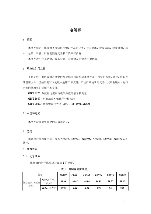
电解镍1范围本文件规定了电解镍(包括电积镍)产品的分类、技术要求、检验方法、检验规则、标志、包装、运输、贮存及随行文件和订货单等内容。
本文件适用于不锈钢、镍基合金、合金钢及电镀等用电解镍。
2规范性引用文件下列文件中的内容通过文中的规范性引用而构成本文件必不可少的条款。
其中,注日期的引用文件,仅该日期对应的版本适用于本文件;不注日期的引用文件,其最新版本(包括所有的修改单)适用于本文件。
GB/T8170数值修约规则与极限数值的表示和判定GB/T8647(所有部分)镍化学分析方法GB/T26022精炼镍取样方法(ISO7156:1991,MOD)3术语和定义本文件没有需要界定的术语和定义。
4分类电解镍产品按化学成分分为Ni9999、Ni9997、Ni9996、Ni9990、Ni9950、Ni9920六个牌号。
5技术要求5.1化学成分电解镍的化学成分应符合表1的规定。
表1电解镍的化学成分5.2外观质量5.2.1产品表面及夹层应洁净,无污泥、油污、电解液等。
注:Ni9950、Ni9920牌号可为不定形电解镍产品。
5.2.2Ni9999、Ni9997、Ni9996、Ni9990牌号电解镍应符合以下规定。
5.2.2.1产品平均厚度不应小于3mm。
5.2.2.2产品边缘不应有树枝状结粒及密集气孔(允许修整)。
5.2.2.3产品表面不应有直径大于3mm的密集气孔,直径3mm密集气孔区总面积不得超过镍板单面面积的15%。
5.2.2.4产品表面高度大于3mm的密集结粒区总面积不应超过镍板单面积15%。
注:25mm×25mm镍板面积上有9个以上气孔或结粒称为密集气孔区或密集结粒区。
5.3其他要求需方如对产品化学成分、物理规格有特殊要求,可由供需双方协商确定并在订货单中注明。
6试验方法6.1产品化学成分的测定按照GB/T8647的规定进行。
6.2产品的外观质量由目视检查。
7检验规则7.1检查与验收7.1.1产品由供方或第三方检验,产品质量应符合本文件及订货单的规定。
- 1、下载文档前请自行甄别文档内容的完整性,平台不提供额外的编辑、内容补充、找答案等附加服务。
- 2、"仅部分预览"的文档,不可在线预览部分如存在完整性等问题,可反馈申请退款(可完整预览的文档不适用该条件!)。
- 3、如文档侵犯您的权益,请联系客服反馈,我们会尽快为您处理(人工客服工作时间:9:00-18:30)。
汽车排气系统用SUH409L不锈钢
冷轧钢带(板)
Ⅰ汽车排气系统用SUH409L不锈钢冷轧钢带(板)技术规范
1 范围
本规范规定了汽车排气系统用SUH409L不锈钢冷轧钢带(板)的尺寸、外形、技术要求、检测规则、包装、标志及质量证明书等。
2 尺寸、外形及允许的偏差
2.1 钢带(板)的尺寸及允许的偏差
2.1.1 钢带(板)的公称厚度及允许偏差应符合表1的规定
表1 钢带(板)的公称厚度及允许偏差单位:mm
2.1.2 钢带(板)公称宽度及允许偏差应符合表2 的规定
表2 钢带钢带(板)公称宽度及允许偏差单位:mm
2.1.3 钢板公称长度及允许偏差应符合表3的规定
表3 钢板公称长度及允许偏差单位:mm
3技术要求
3.1 牌号及化学成分
3.1.1牌号:SUH409L
3.1.2 化学成分(熔炼成分)符合表4的规定
表 4 化学成分单位:%
3.2 交货状态
3.2.1 2B、2D表面
3.2.2 钢带(板)冷轧后经适当的热处理,并进行酸洗或类似的处理、平整。
3.2.3 钢带一般应成卷交货。
按需方要求,并在合同中注明可按钢板交货。
3.3 力学性能
经热处理的钢带(板)力学性能应符合表5的规定
表 5 热处理的钢带(板)力学性能
3.4 表面加工等级及质量要求
3.4.1 钢带(板)表面加工等级应符合GB/T3280中规定的规定
3.4.2 钢带不得有分层,钢带(板)表面不得有气泡、加渣、结疤、氧化皮及欠酸、过酸等影响使用的缺陷。
3.5 晶粒度要求
按GBT 6394-2002 《金属平均晶粒度测定方法》检测,晶粒度应达到5级以上。
4 试验方法
取样部位、取样数量及试验方法应符合表6的规定
表 6 取样部位、取样数量及试验方法
5 检验规则
5.1 出厂检验由供方检验人员进行。
5.2 若某项目检验不符合本标准要求时,允许按GB/247的规定进行复检。
6 包装、标志和质量证明书应符合GB/247的规定。
7 未尽事项应符合GB/T3280的相关规定。