KC02192200-j02-数值比较器使用.
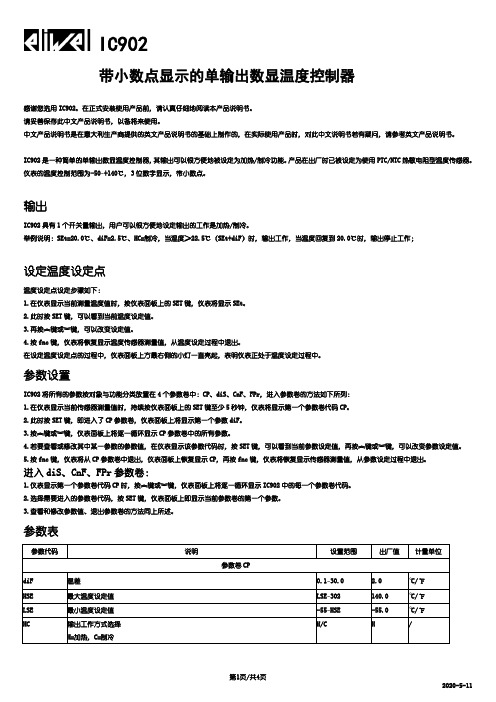
IC902

IC902带小数点显示的单输出数显温度控制器感谢您选用IC902。
在正式安装使用产品前,请认真仔细地阅读本产品说明书。
请妥善保存此中文产品说明书,以备将来使用。
中文产品说明书是在意大利生产商提供的英文产品说明书的基础上制作的,在实际使用产品时,对此中文说明书若有疑问,请参考英文产品说明书。
IC902是一种简单的单输出数显温度控制器,其输出可以很方便地被设定为加热/制冷功能。
产品在出厂时已被设定为使用PTC/NTC热敏电阻型温度传感器。
仪表的温度控制范围为-50~+140℃,3位数字显示,带小数点。
输出IC902具有1个开关量输出,用户可以很方便地设定输出的工作是加热/制冷。
举例说明:SEt=20.0℃、diF=2.5℃、HC=制冷,当温度≥22.5℃(SEt+diF)时,输出工作,当温度回复到20.0℃时,输出停止工作;设定温度设定点温度设定点设定步骤如下:1.在仪表显示当前测量温度值时,按仪表面板上的SET键,仪表将显示SEt。
2.此时按SET键,可以看到当前温度设定值。
3.再按︽键或︾键,可以改变设定值。
4.按fnc键,仪表将恢复显示温度传感器测量值,从温度设定过程中退出。
在设定温度设定点的过程中,仪表面板上方最右侧的小灯一直亮起,表明仪表正处于温度设定过程中。
参数设置IC902将所有的参数按对象与功能分类放置在4个参数卷中:CP、diS、CnF、FPr,进入参数卷的方法如下所列:1.在仪表显示当前传感器测量值时,持续按仪表面板上的SET键至少5秒钟,仪表将显示第一个参数卷代码CP。
2.此时按SET键,即进入了CP参数卷,仪表面板上将显示第一个参数diF。
3.按︽键或︾键,仪表面板上将逐一循环显示CP参数卷中的所有参数。
4.若要查看或修改其中某一参数的参数值,在仪表显示该参数代码时,按SET键,可以看到当前参数设定值,再按︽键或︾键,可以改变参数设定值。
5.按fnc键,仪表将从CP参数卷中退出,仪表面板上恢复显示CP,再按fnc键,仪表将恢复显示传感器测量值,从参数设定过程中退出。
硫磺AMETEK比值分析仪操作规程

880 NSL H2S/SO2 尾气分析仪操作规程一,显示屏提示“MAIN TIMER STOPPED” (2)二,“CELL TEMP/PRESS ALARM” “CELL PRESSURE ALARM ” (2)三,特别在刚开车运行,仪器一进入“SAMPLE CYCLE ”就伴随“LOW LIGHT LEVEL”进入“ZERO CYCLE” (2)四,分析仪已经进入SAMPLE CYCLE 但SO2和H2S浓度%示值均为零。
(2)五,出现EXCESSIVE ZERO ERROR 和 CAL EXCESSIVE ERROR 错误信息 (3)六.出现”LOW LIGHT LEVEL” 光源氙灯不发光或发光频率不规则 (3)七,检查测量气室两个石英窗镜片干净且加热箱两个密封镜片也干净,出现LOW LIGHT LEVEL 报警后进入零气吹扫状态。
(3)八.测量气室温度达不到设定值145C或150C 加热器及温度控制器可以升温但工作不正常分析仪一直处于Zero Cycle。
(4)九.标定时出现效验错误Excessive Cal Error 检查发现四路A,B,C,D标定效验不能与镜片值相同偏差较大。
其他正常。
(4)十.880 比值分析仪光路调整步骤 (4)十一. 880比值仪显示正常但不能升温 (5)十二. 880 NSL H2S/SO2 尾气分析仪开车运行 (5)880尾气分析仪开车条件 (5)880尾气分析仪运行开车 (6)880 NSL H2S/SO2 尾气分析仪常见故障及处理一,显示屏提示“MAIN TIMER STOPPED”控制器时钟被人为终止,请在CONFIG/TEST 菜单下,2级口令进入,选择TIMER 确认ENTER,NOW TIMER IS ON。
即可消除此信息。
二,“CELL TEMP/PRESS ALARM”“CELL PRESSURE ALARM ”此信息提示往往出现在刚刚开车运行阶段,在加热过程中CELL TEMP 还没有达到设定温度范围,即150度+-10度。
对比敏感度仪使用手册(中文)-递交SFDA

对比敏感度仪型号: 62800使用手册OCULUS Optikgeräte GmbHMünchholzhäuser Str。
29,35582 Wetzlar, Germany(德国)版权所有G/62800/0806/e页码2 对比敏感度仪使用手册前言感谢您购买Oculus的产品和对我们的信任。
本产品的生产和检测依据高质量标准,使用本产品能够帮助您进行先进、彻底和全面的检查.对比敏感度仪是一个检查过渡视觉和眩光视敏度的自由空间设备。
对比敏感度仪采用电子控制系统,使得可以进行足够流畅的操作,并且也可以选择通过计算机实现该设备是便携式的。
为使设备安全工作,必须正确使用.因此,在第一次使用设备前,请全面熟悉本使用手册的内容.有问题或希望得到更详细的资料,给我们致电或发传真。
我们的技术部愿意为您提供帮助。
OCULUS Optikgeräte GmbH-经理和全体职员对比敏感度仪使用手册页码3 1。
目录前言 (2)1。
目录 (3)2.设备清单 (4)3。
安全警告 (5)4。
设备和设备功能描述 (6)4.1设备元件 (6)4。
2设备描述 (8)4。
3控制键描述 (10)4。
4设备上的警告符号和标记 (12)5适用范围 (12)6首次使用设备 (12)6.1首次使用前 (12)6.2安装和调试 (12)6.3储运说明 (13)7。
运行设备 (14)7。
1在每次使用前 (14)7.2受检者的准备工作 (14)7.3检查步骤 (15)7。
4附加检查 (16)7。
5结果评价 (16)7。
6每次检查后 (16)8.维护 (17)8。
1保护、清洁和消毒 (17)8.2更换观察视窗衬垫 (18)8.3更换熔丝 (19)8。
4更换工作灯 (19)8。
5问题和故障排除 (20)8。
6维护:描述和时间间隔 (20)9.处理 (20)10.保证和维修条款 (21)10.1授权条款 (21)10。
CO2-200 CO2 检测器用户手册说明书

Users Manual • Mode d’emploi• Bedienungshandbuch• Manual d’Uso• Manual de usoCO2-200CO2 MeterCO2-200 CO2 MeterUsers ManualJuly 2009, Rev.1©2009 Amprobe Test Tools.All rights reserved. Printed in ChinaLimited Warranty and Limitation of LiabilityYour Amprobe product will be free from defects in materialand workmanship for 1 year from the date of purchase. This warranty does not cover fuses, disposable batteries or damage from accident, neglect, misuse, alteration, contamination, or abnormal conditions of operation or handling. Resellers are not authorized to extend any other warranty on Amprobe’s behalf. To obtain service during the warranty period, return the product with proof of purchase to an authorized Amprobe Test Tools Service Center or to an Amprobe dealer or distributor. See Repair Section for details. THIS WARRANTY IS YOUR ONLY REMEDY.ALL OTHER WARRANTIES - WHETHER EXPRESS, IMPLIED OR STAUTORY - INCLUDING IMPLIED WARRANTIES OF FITNESS FORA PARTICULAR PURPOSE OR MERCHANTABILITY, ARE HEREBY DISCLAIMED. MANUFACTURER SHALL NOT BE LIABLE FOR ANY SPECIAL, INDIRECT, INCIDENTAL OR CONSEQUENTIAL DAMAGES OR LOSSES, ARISING FROM ANY CAUSE OR THEORY. Since some states or countries do not allow the exclusion or limitation of an implied warranty or of incidental or consequential damages, this limitation of liability may not apply to you.RepairAll test tools returned for warranty or non-warranty repair orfor calibration should be accompanied by the following: your name, company’s name, address, telephone number, and proof of purchase. Additionally, please include a brief description of the problem or the service requested and include the test leads with the meter. Non-warranty repair or replacement charges should be remitted in the form of a check, a money order, credit card with expiration date, or a purchase order made payable to Amprobe® Test Tools.In-Warranty Repairs and Replacement – All CountriesPlease read the warranty statement and check your battery before requesting repair. During the warranty period any defective test tool can be returned to your Amprobe® Test Tools distributorfor an exchange for the same or like product. Please check the “Where to Buy” section on for a list of distributors near you. Additionally, in the United States and Canada In-Warranty repair and replacement units can also be sent to a Amprobe® Test Tools Service Center (see address below).Non-Warranty Repairs and Replacement – US and CanadaNon-warranty repairs in the United States and Canada should be sent to a Amprobe® Test Tools Service Center. Call Amprobe® Test Tools or inquire at your point of purchase for current repair and replacement rates.In USA In CanadaAmprobe Test Tools Amprobe Test ToolsEverett, WA 98203 Mississauga, ON L4Z 1X9Tel: 877-AMPROBE (267-7623) Tel: 905-890-7600Non-Warranty Repairs and Replacement – EuropeEuropean non-warranty units can be replaced by your Amprobe® Test Tools distributor for a nominalv charge. Please check the “Where to Buy” section on for a list of distributors near you.European Correspondence Address*Amprobe® Test Tools EuropeIn den Engematten 1479286 Glottertal, GermanyTel.: +49 (0) 7684 8009 - 0*(Correspondence only – no repair or replacement available from this address. European customers please contact your distributor.)CO2-200 CO2 Meter1 3 5 7 9 11Humidity SensorAlarm OutputDC JackCAL/ESC ButtonDP/WB ButtonBeeper24681012LCD DisplayUSB PortSET ButtonRESET ButtonMNX/AV ButtonLED LightLCD DisplayPrimary Screen Displays CO2 Concentration Relative Humidity In %Air, Dew Point, Wet Bulb T emperature Display CO2 Measurement Mode Minimum/Maximum readingsTime Weighted Average (8 Hours)Short-T erm Exposure Limit (15 Minutes Weighted Average)Dew Point T emperatureAir temperatureWet Bulb T emperature12345791068CONTENTS SYMBOLS (2)UNPACKING AND INSPECTION (2)INTRODUCTION (3)Features (3)OPERATION (4)Alarm output (5)Setup (6)Calibration Mode (7)• CO2 calibration (8)• Manual calibration (8)• Humidity calibration (7)USB Interface capabilities (8)SPECIFICATIONS (9)MAINTENANCE (10)TROUBLE SHOOTING (11)APPENDIX (12)1SYMBOLS�Caution! Refer to the explanation in this Manual�Conforms to relevant Australian standards�Complies with European Directives=Do not dispose of this clamp meter asunsorted municipal waste. Contact a qualifiedrecycler for disposal.�Warning and Precautions• Avoid condensation on CO2 sensor• Do not hold the meter close to faces in caseexhalation affects CO2 levels.• Do not calibrate the meter in the air withunknown CO2 concentration. Otherwise, it willbe calibrated as 400ppm by default and leads toinaccurate measurements.UNPACKING AND INSPECTIONYour shipping carton should include:1 CO2-200 CO2 Meter1 Adaptor1 User manual1 Plain white boxIf any of the items are damaged or missing, returnthe complete package to the place of purchase for an exchange.2INTRODUCTIONThank you for purchasing this CO2 meter. It measures CO2 level, air temp., dew point, wet bulb temp. and humidity and is an ideal instrument for indoor air quality (IAQ) diagnosis.Poor indoor air quality is considered unhealthy because it causes tiredness, loss of ability to concentrate, and even illness (ex. Sick Building Syndrome). IAQ monitoring and survey, especially on CO2 level and air ventilation become widely applied in public areas such as offices, classrooms, factories, hospitals and hotels. It is also suggested in regulations of industrial hygiene in some countries. (Appendix)With NDIR (non-dispersive infrared) sensor used, thisCO2 meter is stable in long term monitoring. And the built-in relay for alarm output is especially useful in ventilation control and HVAC system performance verification.Features• Triple displays of CO2 level, temp. and humidity.• Stable NDIR sensor for CO2 detection.• Statistics of weighted averages (TWA & STEL)• Visible and audile CO2 warning alarm• Alarm output for ventilation control• Battery and adaptor power supply• ABC(Automatic Baseline Calibration) and manualCO2 calibration• USB PC connection3OPERATION1. Plug in the adaptor and the meter turns onautomatically with a short beep. It performs30 seconds countdown (Fig.1) for meter warmup, then enters normal mode with current CO2,temperature, and humidity readings displayed.2. The meter starts taking measurements whenpower on and updates readings every second. Inthe condition of operating environment change(ex. from high to low temp.), it takes 30 sec torespond for CO2 sensor and 30 minutes for RH.3. Press “p/DP/WB” to switch temperaturesdisplay. The lower left display will cycle from airtemperature, dew point temp., and wet bulbtemp. (Fig. 2)4. Press “MNX/AVG/q” to see the minimum,maximum, and weighted average readings.Each press of it displays MIN, MAX, STEL, TWA insequence and returns to normal mode. In MIN andMAX modes, it shows the minimum and maximumreadings of CO2 on main display, and of AIR/DP/WBT temperatures and humidity on the lowerdisplays. In STEL and TWA modes, the main displayshows the weighted average of CO2 readings forthe past 15 minutes (STEL) and 8 hours(TWA), butthe lower displays are the current AIR, DP/WBtemperatures and humidity readings.NOTE:• If the meter is turned on for shorter than 15minutes, the STEL value will be the weightedaverage of readings taken since power on. Samefor TWA values appear before 8 hours.• It takes at least 5 minutes to calculate STEL andTWA. The display shows “----” during the first 5minutes from power on (Fig. 3).4Alarm OutputThe meter features visible and audible alarm to give warnings when CO2 concentration exceeds the limit. Users can set up 2 limits: An upper limit for alarm threshold that requires air conditioning and a lower limit to stop the alarm. (See P1.0 in setup for setting alarm limits).It emits beeps(Abt.80dB) with blinking LED when CO2 level goes over the upper limit. Beeps can be stoppedby pressing any key or automatically stops whenCO2 reading falls below lower limit. If the beeper is temporarily shut, it will sound again when readingsfall below lower limit and then go over the upper limit again, or users press “RESET” for more than 1 secondto activate it. LED alarm keeps blinking when beeps are manually shut. It stops only when readings fall under the lower limit.The meter is designed with a relay to send outputfor further connection. When CO2 readings go overthe upper limit and cause alarming. The relay picks up automatically and sends output. It can be connected to a ventilation system or activator for conditioning the air quality. The relay will drop out when CO2 readings fall under the lower limit.SetupThe advanced setup mode lets you customize your meter.3 types parameters are available.P1.0: CO2 AlarmP3.0: Temperature unitP4.0: ABC selectionP1.0 CO2 alarm: upper & lower limitsHold down “SET” under normal mode for more than 1 sec to enter set up mode. To exit setup, press “CAL/ESC” in P1.0, P3.0, or P4.0.5When entering setup mode, P1.0 and “AL” are displayed on the LCD (Fig. 4). Press “SET” again to go into P1.1 for setting CO2 upper limit. The current set value will be blinking on LCD (Fig.5). Press “p/DP/WB” to increase the value or “MNX/AVG/q”to decrease. Each press tunes 100 ppm and the alarm range is from 100 to 9900ppm. When the preferred value is set, press “SET” to go into P1.2 for lower limit setting. After both settings are done, press “SET” to save or “CAL/ESC” without saving and return to P1.0.P3.0: Temperature scalePress “p/DP/WB“ in P1.0 to access P3.0 for setting up temperature scale. Press “SET” and it goes into P3.1 with blinking °C or °F current set on the lower left display.To switch °C or °F, press “p/DP/WB “or “MNX/AVG/q”. Then press “SET” to save the setting or “CAL/ESC” without saving and return to P3.0.P4.0: ABC selectionPress “p/DP/WB“ in P3.0 or “MNX/AVG/q” in P1.0 to access P4.0 for selecting ABC function. Press “SET” and it goes into P4.1 with blinking “dis” default (Fig. 6) on the lower left display. To enable the ABC function, press “p/ DP/WB“ or “MNX/AVG/q” and “En” blinks for choice. After the preferred selection is done, press “SET” to save the setting or “CAL/ESC” without saving and return toP4.0.Calibration ModeCO2 calibrationABC (Automatic Baseline Calibration)ABC is to implement baseline calibration toeliminate the zero drift of the NDIR sensor. Itcalibrates the meter at the minimum CO2 readingdetected during 7 days continuous monitoring(power on). It’s not suitable to implement ABC inclose area with higher CO2 level all the time. TheABC default is off. To enable the function, pleaserefer to SETUP P4.0.6Manual calibrationThe manual calibration is suggested to be done inoutdoor area with ventilating fresh air where CO2level is around 400 ppm. Do not calibrate in placescrowded with people or close to where with highCO2 concentration such as ventilating outlets orfireplaces.1. Place the meter in the calibration site. Turn on themeter and hold down “CAL/ESC” and “p/DP/WB“simultaneously to enter CO2 calibration mode.400ppm and “CAL” are blinking on the LCD whileperforming calibration. (Fig. 7)2. Wait about 5 minutes until it stops blinking andthe calibration completes and back to normalmode.3. To abort the calibration, turn “RESET” over asecond.Humidity calibration1. Plug the sensor probe into 33% salt bottle. Holddown “CAL/ESC” and “MNX/AVG/q” undernormal mode to enter 33% calibration. “CAL” andcalibrating value (32.7% if at 25°C) are blinkingon the LCD with current temperature at the left.Meter is now calibrating, and will finish in about60 minutes when “CAL” and humidity value stopblinking.2. After 33% calibration, plug the sensor probe into75% salt bottle, then press “SET” to enter 75%calibration. “CAL” and calibrating value (75.2%if at 25°C) are blinking on the LCD with currenttemperature at the left. Meter is now calibrating.Wait about 60 minutes until blinking stops, thencalibration is completed and it returns to normalmode.73. Users can also calibrate either point. To calibrate33% only, press “CAL/ESC” to exit when 33%calibration is completed. To calibrate 75% only,press “p/DP/WB“ or “MNX/AVG/q” within 5minutes while initializing 33% calibration. And itskips 33% and enters 75% calibration.USB Interface CapabilitiesThe USB cable and software (optional kit) are required to transfer data to a PC. Install the USB driver in the software first before connection. And the connecting protocol is 9600 bps, 8 data bits, no parity.8� - EMC: Conforms to EN61326-1. This product complies with requirements of the following European Community Directives: 89/ 336/ EEC (Electromagnetic Compatibility) and 73/ 23/ EEC(Low Voltage) as amended by 93/ 68/ EEC (CE Marking). However, electrical noise or intense electromagnetic fields in the vicinity of the equipment may disturb the measurement circuit. Measuring instruments will also respond to unwanted signals that may be present within the measurement circuit. Users should exercise care and take appropriate precautions to avoid misleading results whenmaking measurements in the presence of electronic interference.9MAINTENANCEInstrument service personnel. The front panel andcase can be cleaned with a mild solution of detergent and water. Apply sparingly with a soft cloth and allow to dry completely before using. Do not use aromatic hydrocarbons or chlorinated solvents for cleaning. TROUBLE SHOOTINGCan’t power on• Check whether the adaptor is well plugged.Slow response• Check whether air flow channels on the rear wereblocked.Error codeE01: CO2 sensor damaged.E02: The value is under range.E03: The value is over range.E04: The original data error results in this error(RH, DP, WB)E07: Too low voltage to measure CO2. Check if the adaptor output is 12V.E11: Retry humidity calibration.E17: Retry CO2 calibration.E31: Temperature sensor damaged.E34: Humidity sensor damaged.10APPENDIX - CO2 LEVELS AND GUIDELINESNIOSH recommendations250-350 ppm: normal outdoor ambient concentrations 600 ppm: minimal air quality complaints600-1000 ppm: less clearly interpreted1000 ppm: indicates inadequate ventilation; complaints such as headaches, fatigue, and eye/throat irritation will be more widespread. 1000 ppm should be used as an upper limit for indoor levels.ASHRAE Standard 62-1989: 1000ppmCO2 concentration in occupied building should not exceed 1000ppm.Building bulletin 101 (BB101): 1500ppmUK standards for schools say that CO2 at averaged over the whole day(i.e. 9am to 3.30pm) should not exceed 1500ppm.OSHA: 5000ppmTime weighted average over five 8-hour work days should not exceed 5000ppm.Germany, Japan, Australia, UK: 5000ppm8 hours weighted average in occupational exposure limit is 5000ppm.1112。
KXN使用说明书1~6 (校正)

■ 自动联算(AT)功能
自动联算就是自动地测算,联算设定 P.I.D 及 ARW 的最佳定数。 自动联算在投入电源后、升温中或控制稳定时等,在任何时候从任意的状态都 可以开始。
(1)请先完成 P.I.D 及 ARW 以外的设定后,再进行自动联算。 (2)同时按 键和 键时,A.T 显示部的灯熄灭,同时开始自动联算。 (3)自动联算结束后 A.T 显示部的灯熄灭。确认自动联算出的定数时,请按 键
测定值显示器(PV) 设定值显示器(SV) 输入种类的选择 ※输入种类的选择请参照“输入种类表”。
测定值显示器(PV) 设定值显示器(SV) 指示计/调节计
设定值(SV)
内容
0
指示计
1
调解计
摄氏(℃)
设定值(SV)
内容
1
℃
设定值(SV)
内容
0
偏差警报
1
绝对警报
警报功能的种类选择
设定值(SV)
内容
0
范围内警报
1
上限及下限警报
传送输出选择(选择式样)
设定值(SV)
内容
0
有传送输出
1
无传送输出
警报的待机动作选择
设定值(SV)
内容
0
有待机动作
1
无待机动作
测定值(PV) 显示器
内容
小数点位置选择
输入补正值设定
上限警报(ALH) 滞后作用设定
温度设定最大值
设定值(SV)显示器 (设定范围)
备注
0~3
0→0000 1→000.0 2→00.00 3→0.000
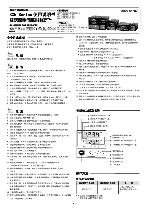
数字式温度控制器
本社/制造商
KXN Series 使用说明书 仁川广域市南区朱安洞 1381-3 TEL:(0082)32-867-0941
hKC-A使用说明书

功能介绍hKC 型多功能仪表用于双螺杆行业主机、主喂料、侧喂料等速度控制与显示,量程可设定。
本仪表的优点是输入信号0~20mA 与0~10V 兼容。
一,主要技术指标1, 数字显示位:双层四位;上层显示测量值,下层显示设定值 ;2, AD 分辨率:0.039V ;3, 继电器输出额定值:24VDC/5A ;(可选)4, 使用环境:-40---+85℃;5, 电源:100~240VAC ;6, 连续工作时间:长期;7, 外形尺寸:48*96*112;8, 电压输入阻抗:20KΩ;9, 电压输出阻抗:500Ω;10, 最大显示值:999.9;二,按键操作说明PV : 显示测量值;在设定状态下显示设定值;SV : 显示设定值;在设定状态下显示设定状态;OUT : 灯亮表示转速或者电流大于设定报警值;操作面板接线端子AL1 : 暂未定义;AL2 : 暂未定义;AT : 暂未定义;+1 :数值加1按钮;-1 :数值减1按钮;+10 :数值加10按钮;-10 :数值减10按钮;+50 :数值加50按钮;-50 :数值减50按钮;三,仪表接线端子说明11: 接AC 输入 L12: 接AC 输入 N17:0~10V (0~20mA)输入+仪表控制系统示意图18:0~10V (0~20mA)输入-19:0~10V 输出+20:0~10V 输出-四,基本操作说明仪表使用前需要设置参数进行初始化。
1,按“SET"按键即进入设置状态当下面一行数码港显示”S-01“,可以通过“+1,-1,移位”按键设定满量程值。
2,再按“SET"按键,当下面一行数码港显示”S-02“即进入零点设置状态如果变频器零位时,仪表输出为“2.3”,此时将上面一排数码管设置为“0023”即可。
3,再按“SET"按键,当下面一行数码港显示”S-03“即进入小数点设置状态0->设定值不含小数位;1->设定值含小数位;4,再按“SET"按键,当下面一行数码港显示”S-04“,上面一行数码管显示“- - - -”,设置结束,待确认。
柯力D30-2 数字显示仪表使用说明书

D30-2数字显示仪表使用说明书●使用前请仔细阅读本产品说明书●请妥善保管本产品说明书,以备查阅、1、 技术参数1、数字传感器接口: DC+12V ,波特率19200 bps,通讯方式RS485,能连接1~4个柯力E 型数字传感器,通讯距离不大于30m ;2、显示: 6位0.8英寸红光LED 数码管,6个状态指示符,3个电池电量指示符; 3、串行通讯接口:通讯方式RS232 ,波特率600~19200可选;4、使用温度: 0℃~40℃, 使用湿度:≤85%(RH )无冷凝;5、存储温度: -10℃~60℃,存贮湿度:≤95%(RH )无冷凝;6、尺寸:240mm × 155mm × 155mm (长×宽×高);7、重量:0.9kg ;第二章 仪 表 安 装 连 接第一节、仪表与数字传感器的连接本仪表只可接E 型数字传感器,接法如下图:第二节、仪表与电脑的连接使用 本仪表的串口通讯方式为RS232:仪表的PC 接口定义 仪表与电脑的RS232连接仪表PC 接口电脑9芯串口223355第三节、仪表与蓄电池的连接使用仪表内部自带电池充电功能模块。
蓄电池请使用12V/7Ah。
第三章按键、指示灯、操作说明第一节、按键、指示灯说明8个轻触按键:【测试/✁】,【功能/ 】,【累加/✐】,【累清/✂】,【标定】,【调秤】,【去皮/取消】,【置零/确认】。
1.复合键说明:按键说明1说明2【测试/✁】【测试】:进入测试界面【✁】:闪烁位数值加1【功能/ 】【功能】:进入参数设置【 】:闪烁位数值减1【累加/✐】【累加】:累加当前净重值【✐】:闪烁位左移一位【累清/✂】【累清】:清除当前累计值【✂】:闪烁位右移一位【去皮/取消】【去皮】:仪表除皮【取消】:返回称重状态【置零/确认】【置零】:仪表回零【确认】:保存当前值【标定】【标定】:进入标定界面【调秤】【调秤】:进入调秤界面2.7位状态指示灯:功能,kg/lb,累加,净重,稳定,零位。
K37A 环保数采仪说明书

前言感谢您购买本公司的产品!感谢您对环保事业做出的贡献!本手册是关于设备的功能、设置、安装、接线方法、操作方法、故障时的处理方法等的说明书。
在操作之前请仔细阅读本手册,正确使用。
请将本手册妥善保存,以便随时翻阅和操作时参考。
注意事项本手册内容如因功能升级而有修改时,恕不另行通知。
如果您在使用过程中对我们的产品或者服务有任何建议或意见,请与我们联系。
说明书版本版本日期内容V2.612019-06-02创建文档V2.622019-12-17修订文档V2.632020-05-12整理文档V2.642020-10-20整理文档V2.652021-05-17整理文档V2.662021-07-05整理文档V2.672021-09-24整理文档请安全使用本设备为了您能安全使用本设备,操作时请务必遵守下述安全注意事项。
如果不按照本手册的说明操作,有导致设备不能正常使用的可能,甚至有导致损坏设备的危险,如因此导致设备故障,我司不承担责任。
警告●只有受过培训的专职人员才能进行设备安装调试和操作。
●接通电源之前请确认设备的电源电压是否与供电电压一致。
●电源需要有接地端。
●必须在设备断电的情况下进行接线。
●必须在设备断电的情况下插拔SIM卡。
●未经过培训的人员,不得打开设备外壳。
目录第一章概述 (5)1.1通信方式说明 (5)1.2数据采集原理 (6)1.3产品特点 (6)第二章产品技术参数 (8)2.1外形图 (8)2.2技术参数 (9)2.3使用条件 (9)第三章安装调试时各注意事项 (10)3.1设备安装尺寸 (10)3.2安装注意事项 (11)3.3接线前准备 (11)3.4接线说明 (12)3.5LED指示灯说明 (14)3.6跳线说明 (14)3.7调试与仪表通信前准备 (14)3.8调试与监控平台联网前准备 (14)3.9设备维护与保养 (15)3.10设备保修 (15)第四章K37A环保数采仪操作简介 (16)4.1页面布局 (16)4.2控件 (17)4.3菜单 (21)第五章实时数据 (22)5.1实时数据总体浏览 (22)5.2实时数据和仪表状态详细浏览 (23)第六章数字站房拓扑图 (25)6.1数字站房拓扑图 (25)6.2菜单栏 (26)第七章参数设置 (27)7.1基本参数 (27)7.2模拟量 (31)7.2.1模拟量参数设置界面 (32)7.2.2选择污染物 (34)7.2.2.1自定义添加污染物 (34)7.2.3查看模拟量信号 (36)7.3串口 (36)7.3.1选择采集数据或输出数据 (37)7.3.2.1指定污染物选择仪表名称参数设置详细说明 (38)7.3.2.2串口采集数据参数详细说明 (40)7.3.2.3指定通用协议仪表选择污染物详细参数设置说明 (41)7.3.2.4数据输出参数设置说明 (44)7.3.3串口自检操作说明 (46)7.3.4串口调试详细说明 (47)7.3.5串口数据详细说明 (48)7.4开关量 (49)7.5本地网络 (50)7.6平台 (51)7.6.1平台参数设置功能说明 (52)7.6.2数据处理操作说明 (54)7.7用户管理 (58)7.7.1添加用户操作说明 (60)第八章仪表管理 (61)8.1仪表控制 (61)8.2仪表参数 (64)第九章智能监控 (66)9.1超标监控 (66)9.2采水控制 (67)9.2.1采水设置 (67)9.2.2核查设置 (72)9.2.3校准设置 (73)9.2.4手动调试 (74)9.2.5水质流程日志 (77)9.3总量控制 (78)9.4摄像头管理 (79)9.5短信通知 (82)第十章日志管理 (84)10.1门禁日志 (84)10.2登录日志 (85)10.3巡检日志 (87)10.4操作日志 (88)10.5平台日志 (90)10.6运行日志 (92)第十一章查询数据 (95)11.1查询数据 (95)11.2查询各种类型的数据说明 (96)11.3单个污染因子数据曲线图 (99)第十二章系统设置 (103)12.1设备信息 (103)12.2站点信息 (104)12.3通用设置 (106)12.4参数备份 (107)12.5系统升级 (108)附件1模拟量通道校准步骤 (110)附件2升级和维护 (112)2.1程序升级说明 (112)2.2远程升级 (113)2.3USB升级 (115)2.4WEB远程管家 (116)2.5USB导出历史数据 (118)附件3售后服务..................................................................错误!未定义书签。
