HWMP_FS_Toxics_Packaging
linux 安装vmare tools
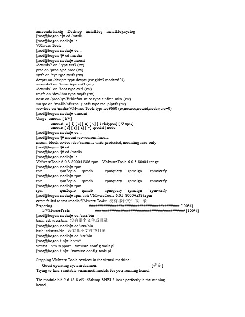
anaconda-ks.cfg Desktop install.log install.log.syslog[root@bogon ~]# cd /media[root@bogon media]# lsVMware Tools[root@bogon media]# cd ..[root@bogon /]# cd /media[root@bogon media]# mount/dev/sda2 on / type ext3 (rw)proc on /proc type proc (rw)sysfs on /sys type sysfs (rw)devpts on /dev/pts type devpts (rw,gid=5,mode=620)/dev/sda3 on /home type ext3 (rw)/dev/sda1 on /boot type ext3 (rw)tmpfs on /dev/shm type tmpfs (rw)none on /proc/sys/fs/binfmt_misc type binfmt_misc (rw)sunrpc on /var/lib/nfs/rpc_pipefs type rpc_pipefs (rw)/dev/hdc on /media/VMware Tools type iso9660 (ro,noexec,nosuid,nodev,uid=0)[root@bogon media]# umountUsage: umount [-hV]umount -a [-f] [-r] [-n] [-v] [-t vfstypes] [-O opts]umount [-f] [-r] [-n] [-v] special | node...[root@bogon media]# cd ..[root@bogon /]# mount /dev/cdrom /mediamount: block device /dev/cdrom is write-protected, mounting read-only[root@bogon /]# cd ..[root@bogon /]# cd /media[root@bogon media]# lsVMwareTools-6.0.3-80004.i386.rpm VMwareTools-6.0.3-80004.tar.gz[root@bogon media]# rpmrpm rpm2cpio rpmdb rpmquery rpmsign rpmverify[root@bogon media]# rpmrpm rpm2cpio rpmdb rpmquery rpmsign rpmverify[root@bogon media]# rpmrpm rpm2cpio rpmdb rpmquery rpmsign rpmverify[root@bogon media]# rpm -ivh VMwareTools-6.0.3-80004.i386.rpmerror: failed to stat /media/VMware Tools: 没有那个文件或目录Preparing... ########################################### [100%] 1:VMwareTools ########################################### [100%] [root@bogon media]# cd /user/binbash: cd: /user/bin: 没有那个文件或目录[root@bogon media]# cd/user/binbash: cd/user/bin: 没有那个文件或目录[root@bogon media]# cd /usr/bin[root@bogon bin]# ls vm*vmstat vm-support vmware-config-tools.pl[root@bogon bin]# ./vmware-config-tools.plStopping VMware Tools services in the virtual machine:Guest operating system daemon: [确定]Trying to find a suitable vmmemctl module for your running kernel.The module bld-2.6.18-8.el5-i686smp-RHEL5 loads perfectly in the runningkernel.Trying to find a suitable vmhgfs module for your running kernel.The module bld-2.6.18-8.el5-i686smp-RHEL5 loads perfectly in the running kernel.pcnet32 35269 0Unloading pcnet32 moduleTrying to find a suitable vmxnet module for your running kernel.The module bld-2.6.18-8.el5-i686smp-RHEL5 loads perfectly in the running kernel.Trying to find a suitable vmblock module for your running kernel.The module bld-2.6.18-8.el5-i686smp-RHEL5 loads perfectly in the running kernel.[EXPERIMENTAL] The V irtual Machine Communication Interface (VMCI) service provides a new communication capability with the Host, primarily for development at the moment. Would you like to enable this feature? [no] yesTrying to find a suitable vmci module for your running kernel.The module bld-2.6.18-8.el5-i686smp-RHEL5 loads perfectly in the running kernel.Detected version 7.1.Please choose one of the following display sizes that X will start with (1 -15):[1] "640x480"[2]< "800x600"[3] "1024x768"[4] "1152x864"[5] "1280x800"[6] "1152x900"[7] "1280x1024"[8] "1376x1032"[9] "1400x900"[10] "1400x1050"[11] "1440x900"[12] "1680x1050"[13] "1600x1200"[14] "1920x1200"[15] "2364x1773"Please enter a number between 1 and 15:[2] 3Argument "redhat" isn't numeric in numeric eq (==) at ./vmware-config-tools.pl line 5856, <EXISTINGXF86CONFIG> line 7.Argument "redhat" isn't numeric in numeric eq (==) at ./vmware-config-tools.pl line 5856, <EXISTINGXF86CONFIG> line 7.Argument "redhat" isn't numeric in numeric eq (==) at ./vmware-config-tools.pl line 5893, <EXISTINGXF86CONFIG> line 30.Argument "redhat" isn't numeric in numeric eq (==) at ./vmware-config-tools.pl line 5893, <EXISTINGXF86CONFIG> line 30.X Window System V ersion 7.1.1Release Date: 12 May 2006X Protocol V ersion 11, Revision 0, Release 7.1.1Build Operating System: Linux 2.6.18-128.1.16.el5 i686 Red Hat, Inc.Current Operating System: Linux bogon 2.6.18-164.el5 #1 SMP Tue Aug 18 15:51:54 EDT 2009 i686 Build Date: 22 July 2009Build ID: xorg-x11-server 1.1.1-48.67.el5Before reporting problems, check to make sure that you have the latest version.Module Loader presentMarkers: (--) probed, (**) from config file, (==) default setting,(++) from command line, (!!) notice, (II) informational,(WW) warning, (EE) error, (NI) not implemented, (??) unknown.(++) Log file: "/tmp/vmware-config0/XF86ConfigLog.3031", Time: Wed Mar 16 10:35:00 2011(++) Using config file: "/tmp/vmware-config0/XF86Config.3031"X is running fine with the new config file.The XKEYBOARD keymap compiler (xkbcomp) reports:> Warning: Multiple symbols for level 1/group 1 on key <I5F>> Using XF86Sleep, ignoring XF86Standby> Warning: Symbol map for key <I5F> redefined> Using last definition for conflicting fieldsErrors from xkbcomp are not fatal to the X serverFreeFontPath: FPE "unix/:7100" refcount is 2, should be 1; fixing.Starting VMware Tools services in the virtual machine:Switching to guest configuration: [确定]Guest filesystem driver: [确定]Mounting HGFS shares: [失败]Guest memory manager: [确定]Guest vmxnet fast network device: [确定]New Host-Guest communications path: [确定]Blocking file system: [确定]DMA setup: [确定]Guest operating system daemon: [确定]The configuration of VMware Tools 6.0.3 build-80004 for Linux for this runningkernel completed successfully.Y ou must restart your X session before any mouse or graphics changes takeeffect.Y ou can now run VMware Tools by invoking the following command:"/usr/bin/vmware-toolbox" during an X server session.To use the vmxnet driver, restart networking using the following commands: /etc/init.d/network stoprmmod pcnet32rmmod vmxnetmodprobe vmxnet/etc/init.d/network startTo make use of the virtual printer, you will need to restart the CUPS service Enjoy,--the VMware team[root@bogon bin]#。
华三路由器软件升级指南

HPUX安全加固大全

一、HPUX设备安全加固项目1、检查是否禁止ip路由转发1、执行备份记录需要修改的可调参数值cp -p /etc/rc.config.d/nddconf /etc/rc.config.d/nddconf_bak2、执行下列命令,设置参数使参数在当前系统状态下临时生效:ndd -set /dev/ip ip_forwarding 0建立启动项,使参数重启后永久生效:cd /etc/rc.config.dcat<<EOF >> nddconf# Don't ip forwardingTRANSPOR T_NAME[0]=ipNDD_NAME[0]= ip_forwardingNDD_V A LUE[0]=0EOFchown root:sys nddconfchmod go-w,ug-s nddconf2、检查口令生存周期要求1、执行备份:cp -p /etc/default/security /etc/default/security_bakcp -p /etc/passwd /etc/passwd_bak2、执行下列命令,编辑/etc/default/security#vi /etc/default/security修改以下各项参数:PASSWORD_MAXDAYS=90PASSWORD_WARNDAYS=28或者采用如下方法:以下的shell语句将设置除root外的所有有效登录的账号密码过期和过前期的收到警告设置:logins -ox \ | awk -F: '($8 != "LK" && $1 != "root") { print $1 }' \ | while read logname; do passwd –x 91 –n 7 –w 28 "$logname" /usr/lbin/modprpw -mexptm=90,mintm=7,expwarn=30 \ "$logname" done echoPASSWORD_MAXDAYS=91 >> /etc/default/security echo PASSWORD_MINDAYS=7 >> /etc/default/security echo PASSWORD_WARNDAYS=28 >> /etc/default/security/usr/lbin/modprdef -m exptm=90,mintm=7,expwarn=30用户将在密码过期前的30天收到警告信息(28 天没有运行在HP-UX 的Trusted 模式)不建议操作3、检查是否关闭inetd中不必要服务1、执行备份:#cp -p /etc/inetd.conf /etc/inetd.conf_bak2、禁止非必要服务:#vi /etc/inetd.conf在非必要服务前面加#注释3、重新启动inetd:#/sbin/init.d/inetd restart执行,关闭的服务需确认4、检查用户缺省UMASK设置默认权限:cd /etcfor file in profile csh.login d.profile d.logindo echo umask 027 >> "$file"donech_rc -a -p UMASK=027 /etc/default/security在/etc目录下的profile csh.login d.profile d.login文件尾部增加umask 027修改文件或目录的权限,操作举例如下:#chmod 444 dir #修改目录dir的权限为所有人都为只读。
Hi3536 SDK 安装以及升级使用说明

Hi3536 SDK 安装以及升级使用说明序1、先明确文中的几个概念。
主片: 多片级联应用中,指PCI主片。
从片: 多片级联应用中,指PCI从片。
主arm:指双CPU中的A17。
从arm:指双CPU中的A7。
第一章 安装SDK1、Hi3536 SDK包位置在"Hi3536_V100R001***/01.software/board"目录下,您可以看到一个 Hi3536_SDK_Vx.x.x.x.tgz 的文件,该文件就是Hi3536的软件开发包。
2、解压缩SDK包在linux服务器上(或者一台装有linux的PC上,主流的linux发行版本均可以),使用命令:tar -zxfHi3536_SDK_Vx.x.x.x.tgz ,解压缩该文件,可以得到一个Hi3536_SDK_Vx.x.x.x目录。
3、展开SDK包内容返回Hi3536_SDK_Vx.x.x.x目录,运行./sdk.unpack(请用root或sudo权限执行)将会展开SDK包打包压缩存放的内容,请按照提示完成操作。
如果您需要通过WINDOWS操作系统中转拷贝SDK包,请先运行./sdk.cleanup,收起SDK包的内容,拷贝到新的目录后再展开。
4、在linux服务器上安装交叉编译器1)安装uclibc交叉编译器(注意,需要有sudo权限或者root权限):进入Hi3536_SDK_Vx.x.x.x/osdrv/opensource/toolchain/arm-hisiv300-linux目录,运行chmod +x cross.v300.install,然后运行./cross.v300.install即可。
2) 安装glibc交叉编译器:进入Hi3536_SDK_Vx.x.x.x/osdrv/opensource/toolchain/arm-hisiv400-linux目录,运行chmod +x cross.v400.install,然后运行./cross.v400.install即可。
【微计算机信息】_环境设备_期刊发文热词逐年推荐_20140724

107 108 109 110 111 112 113 114 115 116 117 118 119 120 121 122 123 124 125 126 127 128 129 130 131 132 133 134 135 136 137 138 139 140 141 142 143 144 145 146 147 148 149 150 151 152 153 154 155 156 157 158 159 160
无人机 数据挖掘 数据仓库 数字无线电台 数字化车间 故障诊断 掌上数控系统 开发环境 干扰 帧时隙 嵌入式实时操作系统 峰数 客户机/服务器 实时 套接字 声卡 基站 图形抽象层(gal) 图像远传 噪声采集 呼吸模式 可编程序控制器 变电站 取证技术 参数整定 参数化 单片机 协同制造 动力环境 制式识别 列车通信 入侵检测 光电控制 便捷式测试仪 体系结构 仿真 人机接口设备 人机接口 人感系统 乳化物 串行外围设备接口总线 中间件 中性束诊断 个性化推荐 上下文感知系统 μ c/os-ⅱ vmic-5565反射内存卡 vc utopia tcp/ip spwm sparc-v8 sopc set协议
科研热词 fpga 蓝牙 节能 数据采集 嵌入式 高速记录应用 高分辨率 飞行模拟机 频谱 音频 面向服务体系架构 集成开发环境(ide) 障碍物分离 链路键值 遥视系统 输入抽象层(ial) 软plc 超声波传感器 起重机远程监控 设备驱动程序 设备驱动dll 设备集成 认知风格 视频监控 虚拟训练 自动控制 自动分离 联机分析 网络化 网格安全 网关 统计原理 红外热成像 系统体系结构 简单配对 移动机器人 睡眠方式 监控终端 电子钱包 生物安全实验室 特征提取 滚动轴承 测试 流媒体 水声传感器网络 机舱综合监测 智能编辑器 智能移动设备 时序 无轴印刷 无线通讯 无线射频识别
NXP SCM-i.MX 6 Series Yocto Linux 用户指南说明书
© 2017 NXP B.V.SCM-i.MX 6 Series Yocto Linux User'sGuide1. IntroductionThe NXP SCM Linux BSP (Board Support Package) leverages the existing i.MX 6 Linux BSP release L4.1.15-2.0.0. The i.MX Linux BSP is a collection of binary files, source code, and support files that can be used to create a U-Boot bootloader, a Linux kernel image, and a root file system. The Yocto Project is the framework of choice to build the images described in this document, although other methods can be also used.The purpose of this document is to explain how to build an image and install the Linux BSP using the Yocto Project build environment on the SCM-i.MX 6Dual/Quad Quick Start (QWKS) board and the SCM-i.MX 6SoloX Evaluation Board (EVB). This release supports these SCM-i.MX 6 Series boards:• Quick Start Board for SCM-i.MX 6Dual/6Quad (QWKS-SCMIMX6DQ)• Evaluation Board for SCM-i.MX 6SoloX (EVB-SCMIMX6SX)NXP Semiconductors Document Number: SCMIMX6LRNUGUser's GuideRev. L4.1.15-2.0.0-ga , 04/2017Contents1. Introduction........................................................................ 1 1.1. Supporting documents ............................................ 22. Enabling Linux OS for SCM-i.MX 6Dual/6Quad/SoloX .. 2 2.1. Host setup ............................................................... 2 2.2. Host packages ......................................................... 23.Building Linux OS for SCM i.MX platforms .................... 3 3.1. Setting up the Repo utility ...................................... 3 3.2. Installing Yocto Project layers ................................ 3 3.3. Building the Yocto image ....................................... 4 3.4. Choosing a graphical back end ............................... 4 4. Deploying the image .......................................................... 5 4.1. Flashing the SD card image .................................... 5 4.2. MFGTool (Manufacturing Tool) ............................ 6 5. Specifying displays ............................................................ 6 6. Reset and boot switch configuration .................................. 7 6.1. Boot switch settings for QWKS SCM-i.MX 6D/Q . 7 6.2. Boot switch settings for EVB SCM-i.MX 6SoloX . 8 7. SCM uboot and kernel repos .............................................. 8 8. References.......................................................................... 8 9.Revision history (9)Enabling Linux OS for SCM-i.MX 6Dual/6Quad/SoloX1.1. Supporting documentsThese documents provide additional information and can be found at the NXP webpage (L4.1.15-2.0.0_LINUX_DOCS):•i.MX Linux® Release Notes—Provides the release information.•i.MX Linux® User's Guide—Contains the information on installing the U-Boot and Linux OS and using the i.MX-specific features.•i.MX Yocto Project User's Guide—Contains the instructions for setting up and building the Linux OS in the Yocto Project.•i.MX Linux®Reference Manual—Contains the information about the Linux drivers for i.MX.•i.MX BSP Porting Guide—Contains the instructions to port the BSP to a new board.These quick start guides contain basic information about the board and its setup:•QWKS board for SCM-i.MX 6D/Q Quick Start Guide•Evaluation board for SCM-i.MX 6SoloX Quick Start Guide2. Enabling Linux OS for SCM-i.MX 6Dual/6Quad/SoloXThis section describes how to obtain the SCM-related build environment for Yocto. This assumes that you are familiar with the standard i.MX Yocto Linux OS BSP environment and build process. If you are not familiar with this process, see the NXP Yocto Project User’s Guide (available at L4.1.15-2.0.0_LINUX_DOCS).2.1. Host setupTo get the Yocto Project expected behavior on a Linux OS host machine, install the packages and utilities described below. The hard disk space required on the host machine is an important consideration. For example, when building on a machine running Ubuntu, the minimum hard disk space required is about 50 GB for the X11 backend. It is recommended that at least 120 GB is provided, which is enough to compile any backend.The minimum recommended Ubuntu version is 14.04, but the builds for dizzy work on 12.04 (or later). Earlier versions may cause the Yocto Project build setup to fail, because it requires python versions only available on Ubuntu 12.04 (or later). See the Yocto Project reference manual for more information.2.2. Host packagesThe Yocto Project build requires that the packages documented under the Yocto Project are installed for the build. Visit the Yocto Project Quick Start at /docs/current/yocto-project-qs/yocto-project-qs.html and check for the packages that must be installed on your build machine.The essential Yocto Project host packages are:$ sudo apt-get install gawk wget git-core diffstat unzip texinfo gcc-multilib build-essential chrpath socat libsdl1.2-devThe i.MX layers’ host packages for the Ubuntu 12.04 (or 14.04) host setup are:$ sudo apt-get install libsdl1.2-dev xterm sed cvs subversion coreutils texi2html docbook-utils python-pysqlite2 help2man make gcc g++ desktop-file-utils libgl1-mesa-dev libglu1-mesa-dev mercurial autoconf automake groff curl lzop asciidocThe i.MX layers’ host packages for the Ubuntu 12.04 host setup are:$ sudo apt-get install uboot-mkimageThe i.MX layers’ host packages for the Ubuntu 14.04 host s etup are:$ sudo apt-get install u-boot-toolsThe configuration tool uses the default version of grep that is on your build machine. If there is a different version of grep in your path, it may cause the builds to fail. One workaround is to rename the special versi on to something not containing “grep”.3. Building Linux OS for SCM i.MX platforms3.1. Setting up the Repo utilityRepo is a tool built on top of GIT, which makes it easier to manage projects that contain multiple repositories that do not have to be on the same server. Repo complements the layered nature of the Yocto Project very well, making it easier for customers to add their own layers to the BSP.To install the Repo utility, perform these steps:1.Create a bin folder in the home directory.$ mkdir ~/bin (this step may not be needed if the bin folder already exists)$ curl /git-repo-downloads/repo > ~/bin/repo$ chmod a+x ~/bin/repo2.Add this line to the .bashrc file to ensure that the ~/bin folder is in your PATH variable:$ export PATH=~/bin:$PATH3.2. Installing Yocto Project layersAll the SCM-related changes are collected in the new meta-nxp-imx-scm layer, which is obtained through the Repo sync pointing to the corresponding scm-imx branch.Make sure that GIT is set up properly with these commands:$ git config --global "Your Name"$ git config --global user.email "Your Email"$ git config --listThe NXP Yocto Project BSP Release directory contains the sources directory, which contains the recipes used to build, one (or more) build directories, and a set of scripts used to set up the environment. The recipes used to build the project come from both the community and NXP. The Yocto Project layers are downloaded to the sources directory. This sets up the recipes that are used to build the project. The following code snippets show how to set up the SCM L4.1.15-2.0.0_ga Yocto environment for the SCM-i.MX 6 QWKS board and the evaluation board. In this example, a directory called fsl-arm-yocto-bsp is created for the project. Any name can be used instead of this.Building Linux OS for SCM i.MX platforms3.2.1. SCM-i.MX 6D/Q quick start board$ mkdir fsl-arm-yocto-bsp$ cd fsl-arm-yocto-bsp$ repo init -u git:///imx/fsl-arm-yocto-bsp.git -b imx-4.1-krogoth -m scm-imx-4.1.15-2.0.0.xml$ repo sync3.2.2. SCM-i.MX 6SoloX evaluation board$ mkdir my-evb_6sxscm-yocto-bsp$ cd my-evb_6sxscm-yocto-bsp$ repo init -u git:///imx/fsl-arm-yocto-bsp.git -b imx-4.1-krogoth -m scm-imx-4.1.15-2.0.0.xml$ repo sync3.3. Building the Yocto imageNote that the quick start board for SCM-i.MX 6D/Q and the evaluation board for SCM-i.MX 6SoloX are commercially available with a 1 GB LPDDR2 PoP memory configuration.This release supports the imx6dqscm-1gb-qwks, imx6dqscm-1gb-qwks-rev3, and imx6sxscm-1gb-evb. Set the machine configuration in MACHINE= in the following section.3.3.1. Choosing a machineChoose the machine configuration that matches your reference board.•imx6dqscm-1gb-qwks (QWKS board for SCM-i.MX 6DQ with 1 GB LPDDR2 PoP)•imx6dqscm-1gb-qwks-rev3 (QWKS board Rev C for SCM-i.MX 6DQ with 1GB LPDDR2 PoP) •imx6sxscm-1gb-evb (EVB for SCM-i.MX 6SX with 1 GB LPDDR2 PoP)3.4. Choosing a graphical back endBefore the setup, choose a graphical back end. The default is X11.Choose one of these graphical back ends:•X11•Wayland: using the Weston compositor•XWayland•FrameBufferSpecify the machine configuration for each graphical back end.The following are examples of building the Yocto image for each back end using the QWKS board for SCM-i.MX 6D/Q and the evaluation board for SCM-i.MX 6SoloX. Do not forget to replace the machine configuration with what matches your reference board.3.4.1. X11 image on QWKS board Rev C for SCM-i.MX 6D/Q$ DISTRO=fsl-imx-x11 imx6dqscm-1gb-qwks-rev3 source fsl-setup-release.sh -b build-x11$ bitbake fsl-image-gui3.4.2. FrameBuffer image on evaluation board for SCM-i.MX 6SX$ DISTRO=fsl-imx-fb MACHINE=imx6sxscm-1gb-evb source fsl-setup-release.sh –b build-fb-evb_6sxscm$ bitbake fsl-image-qt53.4.3. XWayland image on QWKS board for SCM-i.MX 6D/Q$ DISTRO=fsl-imx-xwayland MACHINE=imx6dqscm-1gb-qwks source fsl-setup-release.sh –b build-xwayland$ bitbake fsl-image-gui3.4.4. Wayland image on QWKS board for SCM-i.MX 6D/Q$ DISTRO=fsl-imx-wayland MACHINE=imx6dqscm-1gb-qwks source fsl-setup-release.sh -b build-wayland$ bitbake fsl-image-qt5The fsl-setup-release script installs the meta-fsl-bsp-release layer and configures theDISTRO_FEATURES required to choose the graphical back end. The –b parameter specifies the build directory target. In this build directory, the conf directory that contains the local.conf file is created from the setup where the MACHINE and DISTRO_FEATURES are set. The meta-fslbsp-release layer is added into the bblayer.conf file in the conf directory under the build directory specified by the –e parameter.4. Deploying the imageAfter the build is complete, the created image resides in the <build directory>/tmp/deploy/images directory. The image is (for the most part) specific to the machine set in the environment setup. Each image build creates the U-Boot, kernel, and image type based on the IMAGE_FSTYPES defined in the machine configuration file. Most machine configurations provide the SD card image (.sdcard), ext4, and tar.bz2. The ext4 is the root file system only. The .sdcard image contains the U-Boot, kernel, and rootfs, completely set up for use on an SD card.4.1. Flashing the SD card imageThe SD card image provides the full system to boot with the U-Boot and kernel. To flash the SD card image, run this command:$ sudo dd if=<image name>.sdcard of=/dev/sd<partition> bs=1M && syncFor more information about flashing, see “P reparing an SD/MMC Card to Boot” in the i.MX Linux User's Guide (document IMXLUG).Specifying displays4.2. MFGTool (Manufacturing Tool)MFGTool is one of the ways to place the image on a device. To download the manufacturing tool for the SCM-i.MX 6D/Q and for details on how to use it, download the SCM-i.MX 6 Manufacturing Toolkit for Linux 4.1.15-2.0.0 under the "Downloads" tab from /qwks-scm-imx6dq. Similarly, download the manufacturing tool for the SCM-i.MX 6SoloX evaluation board under the "Downloads" tab from /evb-scm-imx6sx.5. Specifying displaysSpecify the display information on the Linux OS boot command line. It is not dependent on the source of the Linux OS image. If nothing is specified for the display, the settings in the device tree are used. Find the specific parameters in the i.MX 6 Release Notes L4.1.15-2.0.0 (available at L4.1.15-2.0.0_LINUX_DOCS). The examples are shown in the following subsections. Interrupt the auto-boot and enter the following commands.5.1.1. Display options for QWKS board for SCM-i.MX 6D/QHDMI displayU-Boot > setenv mmcargs 'setenv bootargs console=${console},${baudrate} ${smp}root=${mmcroot} video=mxcfb0:dev=hdmi,1920x1080M@60,if=RGB24'U-Boot > run bootcmd5.1.2. Display options for EVB for SCM-i.MX 6SXNote that the SCM-i.MX 6SX EVB supports HDMI with a HDMI accessory card (MCIMXHDMICARD) that plugs into the LCD connector on the EVB.Accessory boards:•The LVDS connector pairs with the NXP MCIMX-LVDS1 LCD display board.•The LCD expansion connector (parallel, 24-bit) pairs with the NXP MCIMXHDMICARD adapter board.LVDS displayU-Boot > setenv mmcargs 'setenv bootargs console=${console},${baudrate} ${smp}root=${mmcroot} ${dmfc} video=mxcfb0:dev=ldb,1024x768M@60,if=RGB666 ldb=sep0'U-Boot > run bootcmdHDMI display (dual display for the HDMI as primary and the LVDS as secondary)U-Boot > setenv mmcargs 'setenv bootargs console=${console},${baudrate} ${smp}root=${mmcroot} video=mxcfb0:dev=hdmi,1920x1080M@60,if=RGB24video=mxcfb1:dev=ldb,LDBXGA,if=RGB666'U-Boot > run bootcmdLCD displayu-boot > setenv mmcargs 'setenv bootargs ${bootargs}root=${mmcroot} rootwait rw video=mxcfb0:dev=lcd,if=RGB565'u-boot> run bootcmd6. Reset and boot switch configuration6.1. Boot switch settings for QWKS SCM-i.MX 6D/QThere are two push-button switches on the QWKS-SCMIMX6DQ board. SW1 (SW3 for QWKS board Rev B) is the system reset that resets the PMIC. SW2 is the i.MX 6Dual/6Quad on/off button that is needed for Android.There are three boot options. The board can boot either from the internal SPI-NOR flash inside the SCM-i.MX6Dual/6Quad or from either of the two SD card slots. The following table shows the switch settings for the boot options.Table 1.Boot configuration switch settingsBoot from top SD slot (SD3)Boot from bottom SD slot (SD2)Boot from internal SPI NORDefault1.References6.2. Boot switch settings for EVB SCM-i.MX 6SoloXThis table shows the jumper configuration to boot the evaluation board from the SD card slot SD3.7. SCM uboot and kernel repositoriesThe kernel and uboot patches for both SCM-i.MX 6 QWKS board and evaluation board are integrated in specific git repositories. Below are the git repos for SCM-i.MX 6 uboot and kernel:uBoot repo: /git/cgit.cgi/imx/uboot-imx.gitSCM Branch: scm-imx_v2016.03_4.1.15_2.0.0_gakernel repo: /git/cgit.cgi/imx/linux-imx.gitSCM branch: scm-imx_4.1.15_2.0.0_ga8. References1.For details about setting up the Host and Yocto Project, see the NXP Yocto Project User’s Guide(document IMXLXYOCTOUG).2.For information about downloading images using U-Boot, see “Downloading images usingU-Boot” in the i.MX Linux User's Guide (document IMXLUG).3.For information about setting up the SD/MMC card, see “P reparing an SD/MMC card to boot” inthe i.MX Linux User's Guide (document IMXLUG).9. Revision historyDocument Number: SCMIMX6LRNUGRev. L4.1.15-2.0.0-ga04/2017How to Reach Us: Home Page: Web Support: /supportInformation in this document is provided solely to enable system and softwareimplementers to use NXP products. There are no express or implied copyright licenses granted hereunder to design or fabricate any integrated circuits based on the information in this document. NXP reserves the right to make changes without further notice to any products herein.NXP makes no warranty, representation, or guarantee regarding the suitability of its products for any particular purpose, nor does NXP assume any liability arising out of the application or use of any product or circuit, and specifically disclaims any and all liability, including without limitation consequentia l or incidental damages. “Typical”parameters that may be provided in NXP data sheets and/or specifications can and do vary in different applications, and actual performance may vary over time. All operating parameters, including “typicals,” must be valida ted for each customer application by customer’s technical experts. NXP does not convey any license under its patent rights nor the rights of others. NXP sells products pursuant to standard terms and conditions of sale, which can be found at the following address: /SalesTermsandConditions .NXP, the NXP logo, NXP SECURE CONNECTIONS FOR A SMARTER WORLD, Freescale, and the Freescale logo are trademarks of NXP B.V. All other product or service names are the property of their respective owners.ARM, the ARM Powered logo, and Cortex are registered trademarks of ARM Limited (or its subsidiaries) in the EU and/or elsewhere. All rights reserved. © 2017 NXP B.V.。
solairs 启动时挂载服务报错

%l4-7: 0000000000000000 0000000001818a28 0000000000000000 0000060010c52e20
rebooting...
Resetting ...
Software Reset
Enabling system bus....... Done
单用户:/tmp/a/sbin/bootadm update-archive -R /tmp/a
/kernel/fs/sparcv9/sockfs: undefined symbol 'sctp_listen'
/kernel/fs/sparcv9/sockfs: undefined symbol 'udp_output'
/kernel/fs/sparcv9/sockfs: undefined symbol 'sctp_recvd'
/kernel/misc/sparcv9/strplumb: undefined symbol 'iscsiboot_prop'
WARNING: mod_load: cannot load module 'strplumb'
panic[cpu2]/thread=180e000: mod_hold_stub: Couldn't load stub module misc/strplumb
rm -f /tmp/a/dev/dsk/c*
rm -f /tmp/a/dev/cfg/c*
sae_j2534-1_2004
SURFACEVEHICLERECOMMENDED PRACTICESAE Technical Standards Board Rules provide that: “This report is published by SAE to advance the state of technical and engineering sciences. The use of this report is entirely voluntary, and its applicability and suitability for any particular use, including any patent infringement arising therefrom, is the sole responsibility of the user.”SAE reviews each technical report at least every five years at which time it may be reaffirmed, revised, or cancelled. SAE invites your written comments and suggestions.Copyright © 2004 SAE InternationalAll rights reserved. No part of this publication may be reproduced, stored in a retrieval system or transmitted, in any form or by any means, electronic, mechanical, photocopying, recording, or otherwise, without the prior written permission of SAE.TO PLACE A DOCUMENT ORDER: Tel: 877-606-7323 (inside USA and Canada)Tel: 724-776-4970 (outside USA)SAE J2534-1 Revised DEC2004TABLE OF CONTENTS 1. Scope (5)2. References (5)2.1 Applicable Documents (5)2.1.1 SAE Publications (5)2.1.2 ISO Documents (6)3. Definitions (6)4. Acronyms (6)5. Pass-Thru C oncept (7)6. Pass-Thru System Requirements (8)6.1 P C Requirements (8)6.2 Software Requirements and Assumptions (8)6.3 Connection to PC (9)6.4 Connection to Vehicle............................................................................................................9 6.5 C ommunication Protocols (9)6.5.1 ISO 9141................................................................................................................................9 6.5.2 ISO 14230-4 (KWP2000).. (10)6.5.3 SAE J1850 41.6 kbps PWM (Pulse Width Modulation) (10)6.5.4 SAE J1850 10.4 kbps VPW (Variable Pulse Width) (10)6.5.5 C AN (11)6.5.6 ISO 15765-4 (CAN) (11)6.5.7 SAE J2610 DaimlerChrysler SCI (11)6.6 Simultaneous Communication on Multiple Protocols (11)6.7 Programmable Power Supply (12)6.8 Pin Usage (13)6.9 Data Buffering (14)6.10 Error Recovery (14)6.10.1 Device Not Connected (14)6.10.2 Bus Errors (14)7. Win32 Application Programming Interface (15)7.1 API Functions – Overview (15)7.2 API Functions - Detailed Information (15)7.2.1 PassThruOpen (15)7.2.1.1 C /C ++ Prototype (15)7.2.1.2 Parameters (16)7.2.1.3 Return Values (16)7.2.2 PassThru C lose (16)7.2.2.1 C /C ++ Prototype (16)7.2.2.2 Parameters (16)7.2.2.3 Return Values (17)7.2.3 PassThru C onnect (17)7.2.3.1 C /C ++ Prototype (17)7.2.3.2 Parameters (17)7.2.3.3 Flag Values (18)7.2.3.4 Protocal ID Values (19)SAE J2534-1 Revised DEC20047.2.3.5 Return Values (20)7.2.4 PassThruDisconnect............................................................................................................20 7.2.4.1 C /C ++ Prototype (20)7.2.4.2 Parameters (21)7.2.4.3 Return Values ......................................................................................................................21 7.2.5 PassThruReadMsgs. (21)7.2.5.1 C /C ++ Prototype (22)7.2.5.2 Parameters...........................................................................................................................22 7.2.5.3 Return Values . (23)7.2.6 PassThruWriteMsgs (23)7.2.6.1 C /C ++ Prototype ..................................................................................................................24 7.2.6.2 Parameters (24)7.2.6.3 Return Values (25)7.2.7 PassThruStartPeriodicMsg..................................................................................................26 7.2.7.1 C /C ++ Prototype (26)7.2.7.2 Parameters (26)7.2.7.3 Return Values ......................................................................................................................27 7.2.8 PassThruStopPeriodicMsg .. (27)7.2.8.1 C /C ++ Prototype (28)7.2.8.2 Parameters...........................................................................................................................28 7.2.8.3 Return Values . (28)7.2.9 PassThruStartMsgFilter.......................................................................................................28 7.2.9.1 C /C ++ Prototype (31)7.2.9.2 Parameters (31)7.2.9.3 Filter Types ..........................................................................................................................32 7.2.9.4 Return Values . (33)7.2.10 PassThruStopMsgFIlter (33)7.2.10.1 C /C ++ Prototype ..................................................................................................................33 7.2.10.2 Parameters (34)7.2.10.3 Return Values (34)7.2.11 PassThruSetProgrammingVoltage (34)7.2.11.1 C /C ++ Prototype (34)7.2.11.2 Parameters (35)7.2.11.3 Voltage Values (35)7.2.11.4 Return Values (35)7.2.12 PassThruReadVersion (36)7.2.12.1 C /C ++ Prototype (36)7.2.12.2 Parameters (36)7.2.12.3 Return Values (37)7.2.13 PassThruGetLastError (37)7.2.13.1 C /C ++ Prototype (37)7.2.13.2 Parameters (37)7.2.13.3 Return Values (37)7.2.14 PassThruIoctl (38)7.2.14.1 C /C ++ Prototype (38)7.2.14.2 Parameters (38)7.2.14.3 Ioctl ID Values (39)7.2.14.4 Return Values (39)7.3 IO C TL Section (40)7.3.1 GET_C ONFIG (41)7.3.2 SET_C ONFIG (42)SAE J2534-1 Revised DEC20047.3.3 READ_VBATT (46)7.3.4 READ_PROG_VOLTAGE....................................................................................................46 7.3.5 FIVE_BAUD_INIT . (47)7.3.6 FAST_INIT (47)7.3.7 C LEAR_TX_BUFFER (48)7.3.8 C LEAR_RX_BUFFER (48)7.3.9 C LEAR_PERIODI C _MSGS (49)7.3.10 C LEAR_MSG_FILTERS (49)7.3.11 C LEAR_FUN C T_MSG_LOOKUP_TABLE (49)7.3.12 ADD_TO_FUN C T_MSG_LOOKUP_TABLE (50)7.3.13 DELETE_FROM_FUN C T_MSG_LOOKUP_TABLE (50)8. Message Structure (51)8.1 C /C ++ Definition (51)8.2 Elements (51)8.3 Message Data Formats (52)8.4 Format Checks for Messages Passed to the API (53)8.5 Conventions for Returning Messages from the API (53)8.6 Conventions for Returning Indications from the API (53)8.7 Message Flag and Status Definitions..................................................................................54 8.7.1 RxStatus. (54)8.7.2 RxStatus Bits for Messaging Status and Error Indication....................................................55 8.7.3 TxFlags.................................................................................................................................56 9. DLL Installation and Registry...............................................................................................57 9.1 Naming of Files....................................................................................................................57 9.2 Win32 Registy. (57)9.2.1 User Application Interaction with the Registry (59)9.2.2 Attaching to the DLL from an application (60)9.2.2.1 Export Library Definition File (61)10. Return Value Error Codes (61)11. Notes (63)11.1 Marginal Indicia (63)Appendix A General ISO 15765-2 Flow Control Example (64)A.1 Flow Control Overview (64)A.1.1 Examples Overview (65)A.2 Transmitting a Segmented Message (66)A.2.1 C onversation Setup (66)A.2.2 Data Transmission (67)A.2.3 Verification (68)A.3 Transmitting an Unsegmented Message (69)A.3.1 Data Transmission (70)A.3.2 Verification (70)A.4 Receiving a Segmented Message (70)A.4.1 C onversation Setup (70)A.4.2 Reception Notification (70)A.4.3 Data Reception (71)A.5 Receiving and Unsegmented Messages (72)1.ScopeThis SAE Recommended Practice provides the framework to allow reprogramming software applications from all vehicle manufacturers the flexibility to work with multiple vehicle data link interface tools from multiple tool suppliers. This system enables each vehicle manufacturer to control the programming sequence for electronic control units (EC Us) in their vehicles, but allows a single set of programming hardware and vehicle interface to be used to program modules for all vehicle manufacturers.This document does not limit the hardware possibilities for the connection between the PC used for the software application and the tool (e.g., RS-232, RS-485, USB, Ethernet…). Tool suppliers are free to choose the hardware interface appropriate for their tool. The goal of this document is to ensure that reprogramming software from any vehicle manufacturer is compatible with hardware supplied by any tool manufacturer.U.S. Environmental Protection Agency (EPA) and the C alifornia Air Resources Board (ARB) "OBD service information" regulations include requirements for reprogramming emission-related control modules in vehicles for all manufacturers by the aftermarket repair industry. This document is intended to conform to those regulations for 2004 and later model year vehicles. For some vehicles, this interface can also be used to reprogram emission-related control modules in vehicles prior to the 2004 model year, and for non-emission related control modules. For other vehicles, this usage may require additional manufacturer specific capabilities to be added to a fully compliant interface. A second part to this document, SAE J2534-2, is planned to include expanded capabilities that tool suppliers can optionally include in an interface to allow programming of these additional non-mandated vehicle applications. In addition to reprogramming capability, this interface is planned for use in OBD compliance testing as defined in SAE J1699-3. SAE J2534-1 includes some capabilities that are not required for Pass-Thru Programming, but which enable use of this interface for those other purposes without placing a significant burden on the interface manufacturers.Additional requirements for future model years may require revision of this document, most notably the inclusion of SAE J1939 for some heavy-duty vehicles. This document will be reviewed for possible revision after those regulations are finalized and requirements are better understood. Possible revisions include SAE J1939 specific software and an alternate vehicle connector, but the basic hardware of an SAE J2534 interface device is expected to remain unchanged.2.References2.1Applicable PublicationsThe following publications form a part of this specification to the extent specified herein. Unless otherwise indicated, the latest version of SAE publications shall apply.2.1.1SAE P UBLICATIONSAvailable from SAE, 400 Commonwealth Drive, Warrendale, PA 15096-0001.SAE J1850—Class B Data Communications Network InterfaceSAE J1939—Truck and Bus Control and Communications Network (Multiple Parts Apply)SAE J1962—Diagnostic ConnectorSAE J2610—DaimlerChrysler Information Report for Serial Data Communication Interface (SCI)2.1.2 ISO D OCUMENTSAvailable from ANSI, 25 west 43rd Street, New York, NY 10036-8002.ISO 7637-1:1990—Road vehicles—Electrical disturbance by conduction and coupling—Part 1:Passenger cars and light commercial vehicles with nominal 12 V supply voltageISO 9141:1989—Road vehicles—Diagnostic systems—Requirements for interchange of digital informationISO 9141-2:1994—Road vehicles—Diagnostic systems—C ARB requirements for interchange of digitalinformationISO 11898:1993—Road vehicles—Interchange of digital information—Controller area network (CAN) forhigh speed communicationISO 14230-4:2000—Road vehicles—Diagnostic systems—Keyword protocol 2000—Part 4:Requirements for emission-related systemsISO/FDIS 15765-2—Road vehicles—Diagnostics on controller area networks (C AN)—Network layerservicesISO/FDIS 15765-4—Road vehicles—Diagnostics on controller area networks (C AN)—Requirements foremission-related systems3.Definitions 3.1 RegistryA mechanism within Win32 operating systems to handle hardware and software configuration information.4. AcronymsAPI Application Programming InterfaceASCII American Standard Code for Information InterchangeCAN Controller Area NetworkC R C C yclic Redundancy C heckDLL Dynamic Link LibraryECU Electronic Control UnitIFR In-Frame ResponseIOCTL Input / Output ControlKWP Keyword ProtocolOEM Original Equipment ManufacturerP C Personal C omputerPWM Pulse Width ModulationSCI Serial Communications InterfaceSCP Standard Corporate ProtocolUSB Universal Serial BusVPW Variable Pulse Width5.Pass-Thru ConceptProgramming application software supplied by the vehicle manufacturer will run on a commonly available generic PC. This application must have complete knowledge of the programming requirements for the control module to be programmed and will control the programming event. This includes the user interface, selection criteria for downloadable software and calibration files, the actual software and calibration data to be downloaded, the security mechanism to control access to the programming capability, and the actual programming steps and sequence required to program each individual control module in the vehicle. If additional procedures must be followed after the reprogramming event, such as clearing Diagnostic Trouble C odes (DTC), writing part numbers or variant coding information to the control module, or running additional setup procedures, the vehicle manufacturer must either include this in the PC application or include the necessary steps in the service information that references reprogramming.This document defines the following two interfaces for the SAE J2534 pass-thru device:a. Application program interface (API) between the programming application running on a PC and asoftware device driver for the pass-thru deviceb. Hardware interface between the pass-thru device and the vehicleThe manufacturer of an SAE J2534 pass-thru device shall supply connections to both the PC and the vehicle. In addition to the hardware, the interface manufacturer shall supply device driver software, and a Windows installation and setup application that will install the manufacturer's SAE J2534 DLL and other required files, and also update the Windows Registry. The interface between the PC and the pass-thru device can be any technology chosen by the tool manufacturer, including RS-232, RS-485, USB, Ethernet, or any other current or future technology, including wireless technologies.All programming applications shall utilize the common SAE J2534 API as the interface to the pass-thru device driver. The API contains a set of routines that may be used by the programming application to control the pass-thru device, and to control the communications between the pass-thru device and the vehicle. The pass-thru device will not interpret the message content, allowing any message strategy and message structure to be used that is understood by both the programming application and the ECU being programmed. Also, because the message will not be interpreted, the contents of the message cannot be used to control the operation of the interface. For example, if a message is sent to the ECU to go to high speed, a specific instruction must also be sent to the interface to go to high speed.The OEM programming application does not need to know the hardware connected to the PC, which gives the tool manufacturers the flexibility to use any commonly available interface to the PC. The pass-thru device does not need any knowledge of the vehicle or control module being programmed. This will allow all programming applications to work with all pass-thru devices to enable programming of all control modules for all vehicle manufacturers.The interface will not handle the tester present messages automatically. The OEM application is responsible to handle tester present messages.6.3Connection to PCThe interface between the PC and the pass-thru device shall be determined by the manufacturer of the pass-thru device. This can be RS-232, USB, Ethernet, IEEE1394, Bluetooth or any other connection that allows the pass-thru device to meet all other requirements of this document, including timing requirements. The tool manufacturer is also required to include the device driver that supports this connection so that the actual interface used is transparent to both the PC programming application and the vehicle.6.4Connection to VehicleThe interface between the pass-thru device and the vehicle shall be an SAE J1962 connector for serial data communications. The maximum cable length between the pass-thru device and the vehicle is five (5) meters. The interface shall include an insulated banana jack that accepts a standard 0.175" diameter banana plug as the auxiliary pin for connection of programming voltage to a vehicle specific connector on the vehicle.If powered from the vehicle, the interface shall:a. operate normally within a vehicle battery voltage range of 8.0 to 18.0 volts D.C.,b. survive a vehicle battery voltage of up to 24.0 volts D.C. for at least 10 minutes,c. survive, without damage to the interface, a reverse vehicle battery voltage of up to 24.0 volts D.C. forat least 10 minutes.6.5Communication ProtocolsThe following communication protocols shall be supported:6.5.1ISO9141The following specifications clarify and, if in conflict with ISO 9141, override any related specifications in ISO 9141:a. The maximum sink current to be supported by the interface is 100 mA.b. The range for all tests performed relative to ISO 7637-1 is –1.0 to +40.0 V.c. The default bus idle period before the interface shall transmit an address, shall be 300 ms.d. Support following baud rate with ±0.5% tolerance: 10400.e. Support following baud rate with ±1% tolerance: 10000.f. Support following baud rates with ±2% tolerance: 4800, 9600, 9615, 9800, 10870, 11905, 12500,13158, 13889, 14706, 15625, and 19200.g. Support other baud rates if the interface is capable of supporting the requested value within ±2%.h. The baud rate shall be set by the application, not determined by the SAE J2534 interface. Theinterface is not required to support baud rate detection based on the synchronization byte.i. Support odd and even parity in addition to the default of no parity, with seven or eight data bits.Always one start bit and one stop bit.j. Support for timer values that are less than or greater than those specified in ISO 9141 (see Figure 30 in Section 7.3.2).k. Support ability to disable automatic ISO 9141-2 / ISO 14230 checksum verification by the interface to allow vehicle manufacturer specific error detection.l. If the ISO 9141 checksum is verified by the interface, and the checksum is incorrect, the message will be discarded.m. Support both ISO 9141 5-baud initialization and ISO 14230 fast initialization.n. Interface shall not adjust timer parameters based on keyword values.6.5.2ISO14230-4(KWP2000)The ISO 14230 protocol has the same specifications as the ISO 9141 protocol as outlined in the previous section. In addition, the following specifications clarify and, if in conflict with ISO 14230, override any related specifications in ISO 14230:a. The pass-thru interface will not automatically handle tester present messages. The application needsto handle tester present messages when required.b. The pass-thru interface will not perform any special handling for the $78 response code. Anymessage received with a $78 response code will be passed from the interface to the application. The application is required to handle any special timing requirements based on receipt of this response code, including stopping any periodic messages.6.5.3SAE J185041.6 KBPS PWM(P ULSE W IDTH M ODULATION)The following additional features of SAE J1850 must be supported by the pass-thru device:a. Capable of 41.6 kbps and high speed mode of 83.3 kbps.b. Recommend Ford approved SAE J1850PWM (SCP) physical layer6.5.4SAE J185010.4 KBPS VPW(V ARIABLE P ULSE W IDTH)The following additional features of SAE J1850 must be supported by the pass-thru device:a. Capable of 10.4 kbps and high speed mode of 41.6 kbpsb. 4128 byte block transferc. Return to normal speed after a break indication6.5.5CANThe following features of ISO 11898 (CAN) must be supported by the pass-thru device:a. 125, 250, and 500 kbpsb. 11 and 29 bit identifiersc. Support for 80% ± 2% and 68.5% ± 2% bit sample pointd. Allow raw C AN messages. This protocol can be used to handle any custom C AN messagingprotocol, including custom flow control mechanisms.6.5.6ISO15765-4(CAN)The following features of ISO 15765-4 must be supported by the pass-thru device:a. 125, 250, and 500 kbpsb. 11 and 29 bit identifiersc. Support for 80% ± 2% bit sample pointd. To maintain acceptable programming times, the transport layer flow control function, as defined inISO 15765-2, must be incorporated in the pass-thru device (see Appendix A). If the application does not use the ISO 15765-2 transport layer flow control functionality, the CAN protocol will allow for any custom transport layer.e. Receive a multi-frame message with an ISO15765_BS of 0 and an ISO15765_STMIN of 0, asdefined in ISO 15765-2.f. No single frame or multi-frame messages can be received without matching a flow control filter. Nomulti-frame messages can be transmitted without matching a flow control filter.g. Periodic messages will not be suspended during transmission or reception of a multi-framesegmented message.6.5.7SAE J2610D AIMLER C HRYSLER SCIReference the SAE J2610 Information Report for a description of the SCI protocol.When in the half-duplex mode (when SCI_MODE of TxFlags is set to {1} Half-Duplex), every data byte sent is expected to be "echoed" by the controller. The next data byte shall not be sent until the echo byte has been received and verified. If the echoed byte received doesn't match the transmitted byte, or if after a period of T1 no response was received, the transmission will be terminated. Matching echoed bytes will not be placed in the receive message queue.6.6Simultaneous Communication On Multiple ProtocolsThe pass-thru device must be capable of supporting simultaneous communication on multiple protocols during a single programming event. Figure 2 indicates which combinations of protocols shall be supported. If SC I (SAE J2610) communication is not required during the programming event, the interface shall be capable of supporting one of the protocols from data link set 1, data link set 2, and data link set 3. If SC I (SAE J2610) communication is required during the programming event, the interface shall be capable of supporting one of the SCI protocols and one protocol from data link set 1.6.9Data BufferingThe interface/API shall be capable of receiving 8 simultaneous messages. For ISO 15765 these can be multi-frame messages. The interface/API shall be capable of buffering a maximum length (4128 byte) transmit message and a maximum length (4128 byte) receive message.6.10Error Recovery6.10.1D EVICE N OT C ONNECTEDIf the DLL returns ERR_DEVICE_NOT_CONNECTED from any function, that error shall continue to be returned by all functions, even if the device is reconnected. An application can recover from this error condition by closing the device (with PassThruC lose) and re-opening the device (with PassThruOpen, getting a new device ID).6.10.2B US E RRORSAll devices shall handle bus errors in a consistent manner. There are two error strategies: Retry and Drop.The Retry strategy will keep trying to send a packet until successful or stopped by the application. If loopback is on and the message is successfully sent after some number of retries, only one copy of the message shall be placed in the receive queue. Even if the hardware does not support retries, the firmware/software must retry the transmission. If the error condition persists, a blocking write will wait the specified timeout and return ERR_TIMEOUT. The DLL must return the number of successfully transmitted messages in pNumMsgs. The DLL shall not count the message being retried in pNumMsgs. After returning from the function, the device does not stop the retries. The only functions that will stop the retries are PassThruDisconnect (on that protocol), PassThruC lose, or PassThruIoctl (with an IoctllD of CLEAR_TX_BUFFER).Devices shall use the Retry strategy in the following scenarios:•All CAN errors, such as bus off, lack of acknowledgement, loss of arbitration, and no connection (lack of terminating resistor)•SAE J1850PWM or SAE J1850VPW bus fault (bus stuck passive) or loss of arbitration (bus stuck active)The Drop strategy will delete a message from the queue. The message can be dropped immediately on noticing an error or at the end of the transmission. PassThruWriteMsg shall treat dropped messages the same as successfully transmitted messages. However, if loopback is on, the message shall not be placed in the receive queue.Devices shall use the Drop strategy in the following scenarios:•If characters are echoed improperly in SCI•Corrupted ISO 9141 or ISO 14230 transmission•SAE J1850PWM lack of acknowledgement (Exception: The device must try sending the message 3 times before dropping)7.2.5.1 C / C++ Prototypeextern “C” long WINAPI PassThruReadMsgs(unsigned long ChannelID,*pMsg,PASSTHRU_MSGunsigned long *pNumMsgs,unsigned long Timeout)7.2.5.2ParametersChannelID The channel ID assigned by the PassThruConnect function.pMsg Pointer to message structure(s).pNumMsgs Pointer to location where number of messages to read is specified. On return from the function this location will contain the actual number of messages read.Timeout Read timeout (in milliseconds). If a value of 0 is specified the function retrieves up to pNumMsgs messages and returns immediately. Otherwise, the API will not return untilthe Timeout has expired, an error has occurred, or the desired number of messageshave been read. If the number of messages requested have been read, the functionshall not return ERR_TIMEOUT, even if the timeout value is zero.When using the ISO 15765-4 protocol, only SingleFrame messages can be transmitted without a matching flow control filter. Also, P I bytes are transparently added by the API. See PassThruStartMsgFilter and Appendix A for a discussion of flow control filters.7.2.6.1 C / C++ Prototypeextern “C” long WINAPI PassThruWriteMsgs(u nsigned long ChannelID,*pMsg,PASSTHRU_MSGunsigned long *pNumMsgs,unsigned long Timeout)7.2.6.2ParametersChannelID The channel ID assigned by the PassThruConnect function.pMsg Pointer to message structure(s).pNumMsgs Pointer to the location where number of messages to write is specified. On return will contain the actual number of messages that were transmitted (when Timeout is non-zero) or placed in the transmit queue (when Timeout is zero).Timeout Write timeout (in milliseconds). When a value of 0 is specified, the function queues as many of the specified messages as possible and returns immediately. When a valuegreater than 0 is specified, the function will block until the Timeout has expired, an errorhas occurred, or the desired number of messages have been transmitted on the vehiclenetwork. Even if the device can buffer only one packet at a time, this function shall beable to send an arbitrary number of packets if a Timeout value is supplied. Since thefunction returns early if all the messages have been sent, there is normally no penalty forhaving a large timeout (several seconds). If the number of messages requested havebeen written, the function shall not return ERR_TIMEOUT, even if the timeout value iszero.W hen an ERR_TIMEOUT is returned, only the number of messages that were sent onthe vehicle network is known. The number of messages queued is unknown. Applicationwriters should avoid this ambiguity by using a Timeout value large enough to work onslow devices and networks with arbitration delays.。
- 1、下载文档前请自行甄别文档内容的完整性,平台不提供额外的编辑、内容补充、找答案等附加服务。
- 2、"仅部分预览"的文档,不可在线预览部分如存在完整性等问题,可反馈申请退款(可完整预览的文档不适用该条件!)。
- 3、如文档侵犯您的权益,请联系客服反馈,我们会尽快为您处理(人工客服工作时间:9:00-18:30)。
Fact Sheet, January 2009
Toxics In Packaging
Information for Manufacturers and Suppliers Introduction
The Department of Toxic Substances Control (DTSC) prepared this fact sheet for manufacturers and suppliers of packaging and packaging components, in order to describe the laws and requirements to institute pollution prevention measures to reduce and eliminate heavy metals in packaging and packaging components. The new approach addresses the pollution problem at the source rather than regulating a material when it becomes a waste. DTSC created this fact sheet to introduce you to the requirements and outline exemptions to the law and the required reporting. You should consult the actual laws to be sure that you are complying.
DTSC is charged with enforcing the requirements of the law that are found in the Health and Safety Code (Health & Saf. Code), sections 25214.11-25214.26, also known as the Toxics in Packaging Prevention Act.
As a manufacturer or supplier, you have the ultimate responsibility to ensure that the packaging and packaging components you produce or provide conform to California law.
Packaging and Packaging Components
Beginning on January 1, 2006, it became illegal to produce, sell, or promote packaging or packaging components that contain cadmium, lead, mercury, or hexavalent chromium, if the metals have been intentionally introduced during manufacture or distribution. However, this law allows selling or promoting packaging containing those metals if their combined presence is incidental and not more than 100 parts per million (ppm) by weight, or the packaging otherwise qualifies for one or more specified exemptions.
A package is any container used for marketing, protecting, or handling a product. This also includes unsealed containers, such as carrying cases, crates, cups, pails, rigid foil and other trays, wrappers and wrapping films, bags, and tubs.
A packaging component is any assembled part of a package, not necessarily limited to any interior or exterior additives. The package component is one produced either domestically or internationally.
Packaging includes packages and packaging components.
Intentional introduction is the deliberate use of the metals as ingredients in the manufacturing or distribution process.
Incidental presence is when one or more of the regulated metals is an unintended or undesired ingredient of packaging.
Manufacturers are required to provide certificates of compliance to the purchaser of the packaging or packaging component stating that the package or packaging component is in compliance with the requirements of this law. Health & Saf. Code section 25214.16 sets out the required contents for this certificate.
Exemptions
There are some exemptions to this law, specified in statute. For example, packaging manufactured and visibly dated prior to January 1, 2006 is exempt. This can be determined by the manufacturing date code on many products. You must provide and retain documentation certifying that the packaging or packaging component is exempt. Another possible exemption is where there is no feasible alternative to the regulated metal(s). Details on the exemption requirements and documentation required are provided in Health & Saf. Code section 25214.15. The manufacturer of the product has a responsibility to provide this certification of exemption to DTSC and the purchaser of the packaging or packaging components.
For a list of other exemptions, please refer to Health & Saf. Code section 25214.14.
Additional Information
For more information about Toxics in Packaging, please visit our website at:
/ToxicsInPackaging/
Our site includes a more general fact sheet, specific information for Manufacturers, Suppliers, and Purchasers, and links to other sites. We also maintain an email list (ListServ) that you may sign up for, so that anyone may receive updates from DTSC regarding Toxics in Packaging.
If you have questions, you can reach us by:
Email: tipinfo@
Telephone: (916) 322-4819
If you would like more information on toxics in packaging, including other states that have these laws, please visit the Toxics in Packaging Clearinghouse. California is a member state. Their phone number is (802) 254-8911, and their website is at .。