Elastic interactions of point defects in a semi-infinite medium
物理学名词
1/4波片quarter-wave plateCG矢量耦合系数Clebsch-Gordan vector coupling coefficient; 简称“CG[矢耦]系数”。
X射线摄谱仪X-ray spectrographX射线衍射X-ray diffractionX射线衍射仪X-ray diffractometer[玻耳兹曼]H定理[Boltzmann] H-theorem[玻耳兹曼]H函数[Boltzmann] H-function[彻]体力body force[冲]击波shock wave[冲]击波前shock front[狄拉克]δ函数[Dirac] δ-function[第二类]拉格朗日方程Lagrange equation[电]极化强度[electric] polarization[反射]镜mirror[光]谱线spectral line[光]谱仪spectrometer[光]照度illuminance[光学]测角计[optical] goniometer[核]同质异能素[nuclear] isomer[化学]平衡常量[chemical] equilibrium constant[基]元电荷elementary charge[激光]散斑speckle[吉布斯]相律[Gibbs] phase rule[可]变形体deformable body[克劳修斯-]克拉珀龙方程[Clausius-] Clapeyron equation[量子]态[quantum] state[麦克斯韦-]玻耳兹曼分布[Maxwell-]Boltzmann distribution[麦克斯韦-]玻耳兹曼统计法[Maxwell-]Boltzmann statistics[普适]气体常量[universal] gas constant[气]泡室bubble chamber[热]对流[heat] convection[热力学]过程[thermodynamic] process[热力学]力[thermodynamic] force[热力学]流[thermodynamic] flux[热力学]循环[thermodynamic] cycle[事件]间隔interval of events[微观粒子]全同性原理identity principle [of microparticles][物]态参量state parameter, state property[相]互作用interaction[相]互作用绘景interaction picture[相]互作用能interaction energy[旋光]糖量计saccharimeter[指]北极north pole, N pole[指]南极south pole, S pole[主]光轴[principal] optical axis[转动]瞬心instantaneous centre [of rotation][转动]瞬轴instantaneous axis [of rotation]t 分布student's t distributiont 检验student's t testK俘获K-captureS矩阵S-matrixWKB近似WKB approximationX射线X-rayΓ空间Γ-spaceα粒子α-particleα射线α-rayα衰变α-decayβ射线β-rayβ衰变β-decayγ矩阵γ-matrixγ射线γ-rayγ衰变γ-decayλ相变λ-transitionμ空间μ-spaceχ 分布chi square distributionχ 检验chi square test阿贝不变量Abbe invariant阿贝成象原理Abbe principle of image formation阿贝折射计Abbe refractometer阿贝正弦条件Abbe sine condition阿伏伽德罗常量Avogadro constant阿伏伽德罗定律Avogadro law阿基米德原理Archimedes principle阿特伍德机Atwood machine艾里斑Airy disk爱因斯坦-斯莫卢霍夫斯基理论Einstein-Smoluchowski theory 爱因斯坦场方程Einstein field equation爱因斯坦等效原理Einstein equivalence principle爱因斯坦关系Einstein relation爱因斯坦求和约定Einstein summation convention爱因斯坦同步Einstein synchronization爱因斯坦系数Einstein coefficient安[培]匝数ampere-turns安培[分子电流]假说Ampere hypothesis安培定律Ampere law安培环路定理Ampere circuital theorem安培计ammeter安培力Ampere force安培天平Ampere balance昂萨格倒易关系Onsager reciprocal relation凹面光栅concave grating凹面镜concave mirror凹透镜concave lens奥温电桥Owen bridge巴比涅补偿器Babinet compensator巴耳末系Balmer series白光white light摆pendulum板极plate伴线satellite line半波片halfwave plate半波损失half-wave loss半波天线half-wave antenna半导体semiconductor半导体激光器semiconductor laser半衰期half life period半透[明]膜semi-transparent film半影penumbra半周期带half-period zone傍轴近似paraxial approximation傍轴区paraxial region傍轴条件paraxial condition薄膜干涉film interference薄膜光学film optics薄透镜thin lens保守力conservative force保守系conservative system饱和saturation饱和磁化强度saturation magnetization本底background本体瞬心迹polhode本影umbra本征函数eigenfunction本征频率eigenfrequency本征矢[量] eigenvector本征振荡eigen oscillation本征振动eigenvibration本征值eigenvalue本征值方程eigenvalue equation比长仪comparator比荷specific charge; 又称“荷质比(charge-mass ratio)”。
超声波探伤英文资料
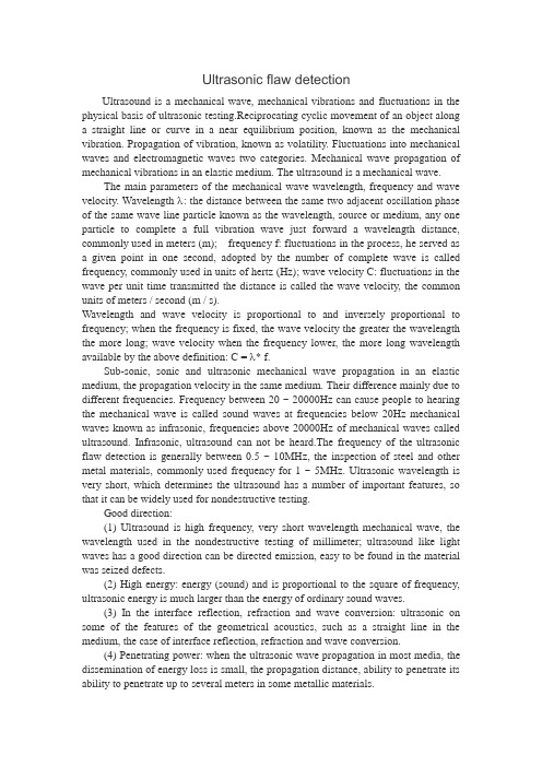
Ultrasonic flaw detectionUltrasound is a mechanical wave, mechanical vibrations and fluctuations in the physical basis of ultrasonic testing.Reciprocating cyclic movement of an object along a straight line or curve in a near equilibrium position, known as the mechanical vibration. Propagation of vibration, known as volatility. Fluctuations into mechanical waves and electromagnetic waves two categories. Mechanical wave propagation of mechanical vibrations in an elastic medium. The ultrasound is a mechanical wave.The main parameters of the mechanical wave wavelength, frequency and wave velocity. Wavelength λ: the distance between the same two adjacent oscillation phase of the same wave line particle known as the wavelength, source or medium, any one particle to complete a full vibration wave just forward a wavelength distance, commonly used in meters (m); frequency f: fluctuations in the process, he served as a given point in one second, adopted by the number of complete wave is called frequency, commonly used in units of hertz (Hz); wave velocity C: fluctuations in the wave per unit time transmitted the distance is called the wave velocity, the common units of meters / second (m / s).Wavelength and wave velocity is proportional to and inversely proportional to frequency; when the frequency is fixed, the wave velocity the greater the wavelength the more long; wave velocity when the frequency lower, the more long wavelength available by the above definition: C = λ* f.Sub-sonic, sonic and ultrasonic mechanical wave propagation in an elastic medium, the propagation velocity in the same medium. Their difference mainly due to different frequencies. Frequency between 20 ~ 20000Hz can cause people to hearing the mechanical wave is called sound waves at frequencies below 20Hz mechanical waves known as infrasonic, frequencies above 20000Hz of mechanical waves called ultrasound. Infrasonic, ultrasound can not be heard.The frequency of the ultrasonic flaw detection is generally between 0.5 ~ 10MHz, the inspection of steel and other metal materials, commonly used frequency for 1 ~ 5MHz. Ultrasonic wavelength is very short, which determines the ultrasound has a number of important features, so that it can be widely used for nondestructive testing.Good direction:(1) Ultrasound is high frequency, very short wavelength mechanical wave, the wavelength used in the nondestructive testing of millimeter; ultrasound like light waves has a good direction can be directed emission, easy to be found in the material was seized defects.(2) High energy: energy (sound) and is proportional to the square of frequency, ultrasonic energy is much larger than the energy of ordinary sound waves.(3) In the interface reflection, refraction and wave conversion: ultrasonic on some of the features of the geometrical acoustics, such as a straight line in the medium, the case of interface reflection, refraction and wave conversion.(4) Penetrating power: when the ultrasonic wave propagation in most media, the dissemination of energy loss is small, the propagation distance, ability to penetrate its ability to penetrate up to several meters in some metallic materials.Ultrasonic flaw detector is the frequency above 20kHz, beyond the people ears to distinguish between talented and penetrating a strong sound waves. Is a portable industrial non-destructive flaw detector, it can be too fast, convenient, no damage to the workpiece internal variety of defects (welds, cracks, folding, loose sand holes, pores, adulterated, etc.), detect, locate, evaluate and diagnostics. Both can be used to carry out the room, can also be used for the project site. Commonly used in boilers, pressure vessels, aerospace, aviation, electric power, petroleum, chemical industry, offshore oil pipeline, military, shipbuilding, automobiles, machinery manufacturing, metallurgy, metal processing industries, steel structures, rail transport, nuclear power, university and other industries.Ultrasonic flaw detector reason: the use of ultrasonic reflection truth nondestructive detection on the defects in the data, when the ultrasound to convey the information to be detected, data acoustic characteristics and the internal organization of the inevitable impact of changes on ultrasonic communication, through ultrasound by affect the level and circumstances of the detection survey data features and skills of the tectonic shift known as ultrasonic testing.Color ultrasonic flaw detector LED display is colorful, multi-color selection, or the premise of divergent light, backlight continuation adjustable, more intuitive to see.There are many about the use of the ultrasonic flaw detector, for example, the reflection of ultrasound to measure the interval, the application of high-power ultrasonic vibration to eliminate the scale attached to the boiler above, the application of high-energy ultrasound made the "harmonic scalpel" to get rid of crushing the human body cancer, stones, etc.The effect and the penetrating power of the ultrasonic flaw detector, the reflection of the application of ultrasound can be a straight line to convey the characteristics of the detection is a great use of areas. Ultrasonic flaw detection using the detection of primary cover various types of information in the industrial and medical testing and diagnosis on the human body, after which one can detect metals and other industrial information, there is no bubble, scars, cracks and other defects can be detected can normal people the body's soft tissue, blood flow.People is how the sample application of ultrasound to detect?Ultrasonic flaw detector is currently mortal is the measured object (for example, industrial information, the human body) emission ultrasound, and then apply the reflection, Doppler effect, transmission to obtain the information inside the measured object and form images through the disposal. Ultrasonic flaw detector, the Doppler effect method is the application of ultrasound in the attack to encounter the object of activities of the Doppler shift effect to draw the characteristics of the activities of the objects bias and speed; transmission rule is parsed ultrasound to penetrate through measured object after the transformation to derive the internal features of objects, their use in the development stage; ultrasonic flaw detector, the first introductions is the way to the most frequently used reflection method to obtain the characteristic information of the object interior. The reflection method is based on ultrasound taskafter the onset of strong reflection of the differences between the acoustic impedance of tissue interface reason, as we know, sound waves from one medium to convey to a medium of hours of the interface between the two will be at the onset of reflection, and the greater the difference between the media reflected the greater will be, so we can launch an object penetrating power, ultrasound can be a straight line to convey the ultrasonic flaw detector and the reflected ultrasonic accepted and this tissue contains various types of media big and small can be determined based on the status of the reflected ultrasound has amplitude ultrasound has spread status and a variety of media cf the difference in the level of information (a reflection back reflects the reflective interface from the detection of the appearance of the interval, the magnitude may reflect the media big and small, mutatis mutandis, to the differences in level and other characteristics), ultrasonic flaw detector and then discriminant of the measured object can have abnormal. The occurrence of touch to a good many in this process, including ultrasound, accepted flags signal of traffic lights and disposal. One of the ultrasonic approach is to encourage electric flags lights after the circuit is passed to the piezoelectric effect of crystal (cristobalite, sulfuric acid, lithium, etc.), so that the vibration and ultrasonic; but to accept the reflected ultrasound after midnight, this pressure the transistor was the pressure of the reflected sound waves will occur electric flags lights and send a series of disposal to the disposal of flags lights circuit, ultrasonic flaw detector constitute the final image for people to look at discrimination.Here based on the image disposal methods (that is to get the flags lights converted to images in what way) the species can be divided into A-type shows, M-type type B, type C, F-type display. A-type display is one of the ultrasound flags will be accepted lights disposal into a waveform image based on the shape of the waveform can be seen that the measured object which can have anomalies and deficiencies in the side, how much, ultrasonic flaw detector first used to industrial inspection; the M-type display is the one through the detection of luminance disposal according to work one by one opened constitute a one-dimensional "space multi-event timing diagram", suitable to look at the internal active form objects, ultrasonic flaw detector, such as activities organs, arteries, etc. Type B shows a lot through the detection of luminance disposal group consisting of two-dimensional side-by-side, which reflects the object's internal fault section of the anatomical images (disease backyard use B super this is the reason to do it), ultrasonic flaw detector is suitable to look internally at static objects; C-type F-type display with unmatched less. Ultrasonic flaw detection will not be very precise, and more convenient compared with other detection methods, fast, nor will it detect objects and operator risk, so were the people more and more throughout the farewell, has a very broad carried out prospects.The development of ultrasound and in the overhaul of the stateAbstract: In the various types of power plant equipment maintenance, service life assessment, the most frequent and widely used in ultrasonic testing technology. Ultrasonic flaw detection applications, applicability, high accuracy, easy automation of a number of advantages. This paper focuses on the crack detection method for ultrasonic inspection technology, quantitative methods of defect, damage, deterioration evaluation methods, and evaluation, and application examples.Key words: ultrasonic testing cracks damage deterioration evaluation applications1 PrefaceMost components of the power plant equipment in the long-term application in high temperature and high pressure water, steam, media, stress, corrosion, creep, hydrogen corrosion and fatigue caused by aging damage and deterioration of a more serious problem. Signal acquisition in the maintenance, service life assessment work on these devices, the most frequent and extensive application of ultrasonic technology. Ultrasonic thin tube to the thick tube, surface to the internal defect information collection is widely used in evaluation of rapid, quantitative defects, easy on-site inspection, analytical, and degree of automation of many of the advantages of it are universally applied.Therefore, to accurately capture these tiny signals, and its resolution, must have high-performance measurement system. In recent years, high sensitivity, high-performance, high reliability of the ultrasonic sending and receiving has been commercialized, along with the increase of high-speed, high-capacity, signal processing, data processing capabilities of computers, image, image analysis, automation is also increasingly easy; in addition, the double crystal probe, focusing the probe surface SH wave probe, climbing wave probe and temperature probe and an electromagnetic ultrasonic non-contact probes such as widely used. In this context, recent analytic in the laboratory stage, the accumulation of basic data, and widely promoted the application of a wide variety of ultrasound assessment of damage and deterioration of diagnostic techniques in the field can be achieved.2 Ultrasonic flaw inspection methodsSo far, have been applied or proposed application of ultrasonic flaw detection nondestructive inspection methods are shown in tables:Defects in quantitative methods equivalent method (equivalent test method, the equivalent calculation method, the equivalent A VG curve method)Length measurement method (relative sensitivity length measuring method, the absolute sensitivity of the length measurement method, the endpoint peak method) The end of wave height methodCrack detection surface wave Supreme CourtSurface wave delay method (single-probe method, dual-probe method)End of the echo peak methodShear-wave side-angle reflection methodSerial transverse wave two-probe methodRelative sensitivity method (6dB, 10dB, 20dB)Scattered wave method (diffraction)Damage, deterioration evaluation method of attenuation (low-level echo reflection method, transmission method, the resonance method)Sonic method (SAW method, the volume method)The critical angle of reflectionSpectrometer method (spectral distribution and size of the center frequency, frequency, amplitude, gravity frequency)Frequency analytical methodBehind the scattering wave clutter analysisOther (δ law, Poisson ratio evaluation method)3 Crack evaluation and application examples3.1 Focused UltrasoundWidely used as a method can be easily measured in the field is the relative sensitivity measurement method. This method is the height of more than echo the probe before and after scanning the distance - amplitude curve (distance amplitude curve to the DAC), the beam away around the threshold to measure the crack height of a method. The accuracy of the method depends on the width of the ultrasonic beam to crack a high degree of measurement accuracy can be increased through the use of ultrasonic amplitude narrow focus probe.Surface occurred in the power generation equipment, water-wall tube corrosion fatigue cracking, stress corrosion cracking and petrochemical equipment alkali corrosion embrittlement crack defects generated by the stainless steel welding parts a high degree of measurement generally used scattering method . The TOFD France BS7706 specified in the method, will launch the probe and receiving probe placed at a certain distance from the weld on both sides of the launch probe emits the spread of longitudinal wave, the crack tip diffracted wave measurement of crack height of. Signal in the crack is only spread in the test surface shear wave and the underlying simple waveform of the reflected wave, but in the case of cracks, but also received from the crack the top and bottom of the diffracted wave. So is the demand on the injury pattern of each signal arrival time difference and these values measure the crack depth and height. Collected reflected signal waveform data converted by computer processing, transform into the phase extent with light and dark gray-scale testing results for real-time image display. In the conventional method, if the angle of incidence deviates from 10 °, the sensitivity was reduced by approximately 25dB, TOFD method is 5dB, relative decrease. It can be said that the TOFD method has good crack detection performance less susceptible to the influence of the crack slope.Japan is studying the use of the large opening angle of the line to focus the probe, so that a leak in the test surface of the elastic wave (LSAW), quantitative evaluation of stainless steel to intergranular attack (IGA) a high degree of method. Experimental results show that the intergranular corrosion itself between the height and the the LSAW echo amplitude have a good relationship.3.2 Surface SH wavesThe average angle probe the shear wave vibration direction in the workpiece in the workpiece surface is perpendicular to the plane of vibration, said SV wave; wave vibration direction and the workpiece parallel to the surface, known as the SH wave. Piezoelectric vibration wave in the role of the inverse piezoelectric effect by the waveform conversion in the heterogeneous interface in the SH wave was seized media.The test proved reciprocating transmittance of the SH wave probe with increasing the angle of refraction of SH-wave probe in steel increases with decreasing frequency was increased, the difference between high and low-frequency probe at different angles the reciprocating transmittance reciprocating transmittance of thefrequency of the probe on a different angle of refraction difference is small. Verify the results compared with the theoretical results, the consistency of the high-frequency probe is better, the consistency of the low-frequency probe somewhat less certain, which is chip considered in the theoretical calculations for the infinite plane, the actual test chip for the finite size . When applied to engineering practice, the SH wave probe is divided into a large angle of SH wave angle probe probe and surface SH wave.Surface SH wave less demanding on the workpiece surface finish, surface SH wave an effective test for greater distance, can improve the efficiency of inspection; applied to the inspection of turbine blades leaves the body to complete the last stage blade length of the test, and is not the final stage blade cavitation. Inspection and vertical tree blade root inspection sensitivity can reach 1mm. Applied to the inner wall fatigue crack inspection, the inspection sensitivity can reach 0.5mm.SH wave probe test sensitivity by coupling effect greatly. This difference was mainly due to the shear wave emitted by the probe SH waves are shear waves, can only be spread in the solid medium. Dedicated shear wave coupling agent at different temperatures, through sound effects quite different, both the shear wave in the reciprocating transmittance of the interface are quite different, resulting in a greater change in the medium wave sound field intensity, resulting in test sensitivity differences. Therefore, practical application, usually used in the ambient temperature is not very different circumstances, if the ambient temperature different response to the testing equipment, test sensitivity is re-calibration. Angle of SH wave angle probe because of the sound field intensity in the range of about 0-10mm under the surface and the surface, the sound field intensity applied to the thin workpiece inspection, the defect location (depth direction) is difficult to be able to accurately locate.Due to surface SH wave has all the advantages described above, so expect to be widely used in non-destructive examination of the structural elements. Flaw detection for the piping of thermal power equipment, such as the use of welded parts of the occurrence of cracks, foreign countries have developed a field-oriented electronic scanning system, and has already begun the application. Such as the use of arc-array probe, the fan-shaped scan of the ultrasonic beam of electrons, the cross-section image of the test body real-time display of the mobile imaging system.4 Damage, deterioration evaluation and application examples4.1 Evaluation of creep damageThe creep damage under high temperature, long time to load a certain load, the intergranular cavities and other phenomena. The ultrasonic evaluation method of its application wave velocity method, the attenuation spectroscopy, frequency resolution and noise analysis, the theoretical analysis are also diverse. Which clutter analysis from the accuracy and applicability of the method is more effective. The approach is from the rear of the metal to structural changes in tissue scattering wave as clutter processing and quantitative evaluation of the amplitude of a method, and then using the integral value of a certain frequency range.4.2 Hydrogen corrosion damage assessmentHydrogen damage in high temperature (> 220 °C) under high pressure conditions, when the boiler water PH <5, the condenser leak, the water supply ofinorganic acids or resin contamination, dirt under the reaction 3Fe +4 H2O → of Fe3O4 +8 [H] generated hydrogen atom scale layer to block the working fluid can not be taken away, then with the grain bo undary carbide reaction of Fe3C +4 of [H] → 3Fe + CH4 ↑, the methane gas generated by the grain boundary cracking, crack or bulge formed in the tube wall, the steel performance degradation of a brittle failure. Hydrogen damage with speed and destruction, damage area, the damage can not be restored, not easy to the characteristics of early detection.High-frequency ultrasound RF echo can be applied to the detection of hydrogen damage μm-level micro-cracks, with coarse sandpaper to remove the pre-test tube the appearance of slag point, the coupling agent on the 28th rolling oil. Therefore, by detecting this echo can understand the internal hydrogen damage microcrack. Generally considered that ultrasound can be found in the smallest defect size as the wavelength 1/2. In recent years, theoretical studies have shown that, if does not require a high degree of echo, and with the high-frequency digital oscilloscope, the instrument sensitivity and signal to noise ratio will be high, the discontinuity detection sensitivity can reach a wavelength of 1/5 ~ 1 / 10. Such as the probe frequency is 15MHz when using the single discontinuity can be detected can be as small as 40μm ~ 75μm.4.3 Sensitive evaluation of the degree ofIf stainless steel is used in high temperature, due to sensitization to generate chromium depletion region is induced intergranular corrosion reasons, ultrasound evaluation of the key is to confirm the correlation between the Poisson's ratio determined by the degree of sensitization and ultrasonic longitudinal and shear waves, sensitive evaluation of Poisson's ratio as an index level of the method is currently being studied.Sensitization of the grain can be seen as the central parts and the parts of the solution in the intergranular elements with different concentrations of shell-like structure, the use of shell-like structure of the scattering body scattering theory to calculate the frequency dependence of ultrasonic speed of sound and attenuation with the increase in the frequency attenuation of the increase in the speed of sound caused by the speed of sound to reduce the development of orientation and sensitization increase tendency is consistent with the experimental values.4.4 Two-phase stainless steel thermal aging evaluationIf the two-phase stainless steel is maintained at 300 ~ 450 ° C for a long time, in the α phase segregation decomposition caused by heat aging (brittle). The speed of sound changes with the thermal aging, from both theoretical and experimental studies have shown that the numerical simulation results and experimental values correspond to good. However, thermal aging on the two-phase stainless steel, cast steel, by casting organizations with coarse particles and its SH wave, the speed of sound and the aging time, although there are some degree of, but found no correlation with the longitudinal wave. In addition, studies have shown that if the use of phase interference method, using the line focus probe leak the speed of sound measurements of the elastic surface wave on a small area, then the speed of sound and thermal aging with the increase in fracture toughness values.4.5 Fatigue evaluationFatigue life evaluation of the application using the axisymmetric SH wave electromagnetic ultrasonic sensor by detecting the attenuation coefficient, non-contact evaluation, and that 90.6% of the rupture life stage, there is the peak of the attenuation coefficient. Fatigue of low alloy steel, the edge dislocation is a straight line model, the spiral dislocation for the bending model, corresponding to the numerical analysis results with the electromagnetic field of ultrasonic measurement of the attenuation coefficient, and proved to the attenuation coefficient changes mainly due to the dislocation.In addition, low cycle fatigue of materials in the application of pulse string waves resonate with attenuation, the attenuation coefficient in the resonance frequency increases with the increase of residual strain, which can predict the degree of fatigue damage. Study for 0Cr19Ni19 stainless steel, measuring the speed of sound using strain control and load control fatigue damage caused by the test body in the strain-controlled fatigue, with increasing fatigue, speed of sound simply reduced, but increased in the load control fatigue. This phenomenon is explained as a phenomenon based on dislocation activities, you need to pay attention to the speed of sound evaluation of fatigue damage.Now, being studied by a strong longitudinal wave ultrasonic incident ultrasonic amplitude dependence of internal friction in the material. The study found that begins by measuring the high harmonic amplitude of the vibration, to determine whether to produce the high cycle fatigue of possibility.5 ConclusionThe use of ultrasound for damage, deterioration diagnosis, need to be able to really understand Suoyu of conclusions; to take full advantage of a variety of evaluation methods, quantitative evaluation, and conclusions from the theory been proven, high sensitivity ultrasonic measurement system, the signal the development of processing and data processing systems development, theoretical analysis and numerical simulation using the computer, etc are essential. But also the need of laboratory and field data accumulation and feedback.超声波探伤超声波是一种机械波,机械振动和波动是超声检测的物理基础。
第3章晶体缺陷
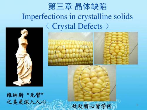
• An interstitial defect is formed when an extra atom is inserted into the crystal structure at a normally unoccupied position. • Interstitial atoms, although much smaller than the atoms located at the lattice points, are still larger than the interstitial sites that they occupy, consequently, the surrounding crystal region is compressed and distorted.
பைடு நூலகம்
• • • • • • • • • •
离开平衡位置的原子有三个去处: 离开平衡位置的原子有三个去处: (1)形成Schottky空位(vacancy) (1)形成 形成Schottky空位 vacancy) 空位( (2)形成Frankely缺陷 (2)形成 形成Frankely缺陷 (3)跑到其它空位上使空位消失或移位。 (3)跑到其它空位上使空位消失或移位 跑到其它空位上使空位消失或移位。 点缺陷的类型: 点缺陷的类型: (1)空位 间隙原子(异类)( )(interstital (2)间隙原子(异类)(interstital atom) 自间隙原子(同类) self(3)自间隙原子(同类) (self- interstital atom ) 外来杂质原子: (4)外来杂质原子: 置换原子( atom) (5)置换原子(substitutional atom) :
Crystal Defects
莞惠城际轨道交通桥梁设计特点与技术创新

莞惠城际面临的新标准、新制式、新模式,对新型城际
载作用、无砟轨道大跨度桥梁徐变控制等技术难题。
轨道交通桥梁设计标准、景观设计、新型结构、大跨混
2. 3 需将景观化设计理念引入铁路桥梁设计中,提
凝土连续梁徐变控制、软土地基偏载作用桩基设计等
出新的铁路桥梁结构形式
莞惠城际穿行于经济发达的珠三角城镇群中,对
Abstract: Dongguan-Huizhou intercity rail transit adopts new standards, new systems and new modes. It
crosses many rivers, where soft soil is extensively distributed, and its landscape is demanding. Its not
莞惠城际线路长,速度目标值为 200 km / h,超出
了当时 GB50157—2003 《 地铁设计规范》
[4]
的适用范
3 主要技术创新
3. 1 提出了适合珠三角城 际 轨 道 交 通 的 新 的 设 计
标准
围。 而如果直接套用当时速度目标值 200 km / h 的铁
3. 1. 1 新的设计活载及相关技术参数
越各级道路、公路几十次。 根据相关产权单位的要求,
常用跨度 30,25 m 满足不了要求,采用了众多特殊结
构,其中( 80 + 150 + 150 + 80) m、( 80 + 150 + 80) m 混凝
土连续梁,(100 + 180 + 100) m 混凝土连续梁拱是当时
同类型桥梁结构中的最大跨度
土木工程专业英语词汇(整理版)
土木工程专业英语词汇(整理版)第一部分必须掌握,第二部分尽量掌握第一部分:1 Finite Element Method 有限单元法2 专业英语 Specialty English3 水利工程 Hydraulic Engineering4 土木工程 Civil Engineering5 地下工程 Underground Engineering6 岩土工程 Geotechnical Engineering7 道路工程 Road (Highway) Engineering8 桥梁工程Bridge Engineering9 隧道工程 Tunnel Engineering10 工程力学 Engineering Mechanics11 交通工程 Traffic Engineering12 港口工程 Port Engineering13 安全性 safety17木结构 timber structure18 砌体结构 masonry structure19 混凝土结构concrete structure20 钢结构 steelstructure21 钢 - 混凝土复合结构 steel and concrete composite structure22 素混凝土 plain concrete23 钢筋混凝土reinforced concrete24 钢筋 rebar25 预应力混凝土 pre-stressed concrete26 静定结构statically determinate structure27 超静定结构 statically indeterminate structure28 桁架结构 truss structure29 空间网架结构 spatial grid structure30 近海工程 offshore engineering31 静力学 statics32运动学kinematics33 动力学dynamics34 简支梁 simply supported beam35 固定支座 fixed bearing36弹性力学 elasticity37 塑性力学 plasticity38 弹塑性力学 elaso-plasticity39 断裂力学 fracture Mechanics40 土力学 soil mechanics41 水力学 hydraulics42 流体力学 fluid mechanics精品文库43 固体力学solid mechanics44 集中力 concentrated force45 压力 pressure46 静水压力 hydrostatic pressure47 均布压力 uniform pressure48 体力 body force49 重力 gravity50 线荷载 line load51 弯矩 bending moment52 扭矩 torque53 应力 stress54 应变 stain55 正应力 normal stress56 剪应力 shearing stress57 主应力 principal stress58 变形 deformation59 内力 internal force60 偏移量挠度 deflection61 沉降settlement62 屈曲失稳 buckle63 轴力 axial force64 允许应力 allowable stress65 疲劳分析 fatigue analysis66 梁 beam67 壳 shell68 板 plate69 桥 bridge70 桩 pile71 主动土压力 active earth pressure72 被动土压力 passive earth pressure73 承载力 load-bearing capacity74 水位 water Height75 位移 displacement76 结构力学 structural mechanics77 材料力学 material mechanics78 经纬仪 altometer79 水准仪level80 学科 discipline81 子学科 sub-discipline82 期刊 journal periodical83 文献literature84 国际标准刊号ISSN International Standard Serial Number精品文库85 国际标准书号ISBN International Standard Book Number86 卷 volume87 期 number88 专著 monograph89 会议论文集 Proceeding90 学位论文 thesis dissertation91 专利 patent92 档案档案室 archive93 国际学术会议 conference94 导师 advisor95 学位论文答辩 defense of thesis96 博士研究生 doctorate student97 研究生 postgraduate98 工程索引EI Engineering Index99 科学引文索引SCI Science Citation Index100 科学技术会议论文集索引ISTP Index to Science and Tec hnology Proceedings101 题目 title102 摘要 abstract103 全文 full-text104 参考文献 reference105 联络单位、所属单位affiliation106 主题词 Subject107 关键字 keyword108 美国土木工程师协会ASCE American Society of Civil Engineers109 联邦公路总署FHWA Federal Highway Administration110 国际标准组织ISO International Standard Organization111 解析方法 analytical method112 数值方法 numerical method113 计算 computation114 说明书 instruction115 规范 Specification Code第二部分:岩土工程专业词汇1.geotechnical engineering 岩土工程2.foundation engineering 基础工程3.soil earth 土4.soil mechanics 土力学5.cyclic loading 周期荷载6.unloading 卸载7.reloading 再加载8.viscoelastic foundation 粘弹性地基9.viscous damping 粘滞阻尼10.shear modulus 剪切模量精品文库11.soil dynamics 土动力学12.stress path 应力路径13.numerical geotechanics 数值岩土力学二.土的分类1.residual soil 残积土 groundwater level 地下水位2.groundwater 地下水 groundwater table 地下水位3.clay minerals 粘土矿物4.secondary minerals 次生矿物ndslides 滑坡6.bore hole columnar section 钻孔柱状图7.engineering geologic investigation 工程地质勘察8.boulder 漂石9.cobble 卵石10.gravel 砂石11.gravelly sand 砾砂12.coarse sand 粗砂13.medium sand 中砂14.fine sand 细砂15.silty sand 粉土16.clayey soil 粘性土17.clay 粘土18.silty clay 粉质粘土19.silt 粉土20.sandy silt 砂质粉土21.clayey silt 粘质粉土22.saturated soil 饱和土23.unsaturated soil 非饱和土24.fill (soil) 填土25.overconsolidated soil 超固结土26.normally consolidated soil 正常固结土27.underconsolidated soil 欠固结土28.zonal soil 区域性土29.soft clay 软粘土30.expansive (swelling) soil 膨胀土31.peat 泥炭32.loess 黄土33.frozen soil 冻土24.degree of saturation 饱和度25.dry unit weight 干重度26.moist unit weight 湿重度45.ISSMGE=International Society for Soil Mechanics and Geotechnical Engineering 国际土力学与岩土工程学会精品文库四.渗透性和渗流1.Darcy’s law 达西定律2.piping 管涌3.flowing soil 流土4.sand boiling 砂沸5.flow net 流网6.seepage 渗透(流)7.leakage 渗流8.seepage pressure 渗透压力9.permeability 渗透性10.seepage force 渗透力11.hydraulic gradient 水力梯度12.coefficient of permeability 渗透系数五.地基应力和变形1.soft soil 软土2.(negative) skin friction of driven pile 打入桩(负)摩阻力3.effective stress 有效应力4.total stress 总应力5.field vane shear strength 十字板抗剪强度6.low activity 低活性7.sensitivity 灵敏度8.triaxial test 三轴试验9.foundation design 基础设计10.recompaction 再压缩11.bearing capacity 承载力12.soil mass 土体13.contact stress (pressure)接触应力(压力)14.concentrated load 集中荷载15.a semi-infinite elastic solid 半无限弹性体16.homogeneous 均质17.isotropic 各向同性18.strip footing 条基19.square spread footing 方形独立基础20.underlying soil (stratum strata)下卧层(土)21.dead load =sustained load 恒载持续荷载22.live load 活载23.short –term transient load 短期瞬时荷载24.long-term transient load 长期荷载25.reduced load 折算荷载26.settlement 沉降27.deformation 变形28.casing 套管精品文库29.dike=dyke 堤(防)30.clay fraction 粘粒粒组31.physical properties 物理性质32.subgrade 路基33.well-graded soil 级配良好土34.poorly-graded soil 级配不良土35.normal stresses 正应力36.shear stresses 剪应力37.principal plane 主平面38.major (intermediate minor) principal stress 最大(中、最小)主应力39.Mohr-Coulomb failure condition 摩尔-库仑破坏条件40.FEM=finite element method 有限元法41.limit equilibrium method 极限平衡法42.pore water pressure 孔隙水压力43.preconsolidation pressure 先期固结压力44.modulus of compressibility 压缩模量45.coefficent of compressibility 压缩系数pression index 压缩指数47.swelling index 回弹指数48.geostatic stress 自重应力49.additional stress 附加应力50.total stress 总应力51.final settlement 最终沉降52.slip line 滑动线六.基坑开挖与降水1 excavation 开挖(挖方)2 dewatering (基坑)降水3 failure of foundation 基坑失稳4 bracing of foundation pit 基坑围护5 bottom heave=basal heave (基坑)底隆起6 retaining wall 挡土墙7 pore-pressure distribution 孔压分布8 dewatering method 降低地下水位法9 well point system 井点系统(轻型)10 deep well point 深井点11 vacuum well point 真空井点12 braced cuts 支撑围护13 braced excavation 支撑开挖14 braced sheeting 支撑挡板七.深基础--deep foundation1.pile foundation 桩基础1)cast –in-place 灌注桩diving casting cast-in-place pile 沉管灌注桩bored pile 钻孔桩special-shaped cast-in-place pile 机控异型灌注桩piles set into rock 嵌岩灌注桩rammed bulb pile 夯扩桩2)belled pier foundation 钻孔墩基础drilled-pier foundation 钻孔扩底墩under-reamed bored pier3)precast concrete pile 预制混凝土桩4)steel pile 钢桩steel pipe pile 钢管桩steel sheet pile 钢板桩5)prestressed concrete pile 预应力混凝土桩prestressed concrete pipe pile 预应力混凝土管桩2.caisson foundation 沉井(箱)3.diaphragm wall 地下连续墙截水墙4.friction pile 摩擦桩5.end-bearing pile 端承桩6.shaft 竖井;桩身7.wave equation analysis 波动方程分析8.pile caps 承台(桩帽)9.bearing capacity of single pile 单桩承载力teral pile load test 单桩横向载荷试验11.ultimate lateral resistance of single pile 单桩横向极限承载力12.static load test of pile 单桩竖向静荷载试验13.vertical allowable load capacity 单桩竖向容许承载力14.low pile cap 低桩承台15.high-rise pile cap 高桩承台16.vertical ultimate uplift resistance of single pile 单桩抗拔极限承载力17.silent piling 静力压桩18.uplift pile 抗拔桩19.anti-slide pile 抗滑桩20.pile groups 群桩21.efficiency factor of pile groups 群桩效率系数(η)22.efficiency of pile groups 群桩效应23.dynamic pile testing 桩基动测技术24.final set 最后贯入度25.dynamic load test of pile 桩动荷载试验26.pile integrity test 桩的完整性试验27.pile head=butt 桩头28.pile tip=pile point=pile toe 桩端(头)29.pile spacing 桩距30.pile plan 桩位布置图31.arrangement of piles =pile layout 桩的布置32.group action 群桩作用33.end bearing=tip resistance 桩端阻34.skin(side) friction=shaft resistance 桩侧阻35.pile cushion 桩垫36.pile driving(by vibration) (振动)打桩37.pile pulling test 拔桩试验38.pile shoe 桩靴39.pile noise 打桩噪音40.pile rig 打桩机九.固结 consolidation1.Terzzaghi’s consolidation theory 太沙基固结理论2.Barraon’s consolidation theory 巴隆固结理论3.Biot’s consolidation theory 比奥固结理论4.over consolidation ration (OCR)超固结比5.overconsolidation soil 超固结土6.excess pore water pressure 超孔压力7.multi-dimensional consolidation 多维固结8.one-dimensional consolidation 一维固结9.primary consolidation 主固结10.secondary consolidation 次固结11.degree of consolidation 固结度12.consolidation test 固结试验13.consolidation curve 固结曲线14.time factor Tv 时间因子15.coefficient of consolidation 固结系数16.preconsolidation pressure 前期固结压力17.principle of effective stress 有效应力原理18.consolidation under K0 condition K0 固结十.抗剪强度 shear strength1.undrained shear strength 不排水抗剪强度2.residual strength 残余强度3.long-term strength 长期强度4.peak strength 峰值强度5.shear strain rate 剪切应变速率6.dilatation 剪胀7.effective stress approach of shear strength 剪胀抗剪强度有效应力法 8.total stress approach of shear strength 抗剪强度总应力法9.Mohr-Coulomb theory 莫尔-库仑理论10.angle of internal friction 内摩擦角11.cohesion 粘聚力12.failure criterion 破坏准则13.vane strength 十字板抗剪强度14.unconfined compression 无侧限抗压强度15.effective stress failure envelop 有效应力破坏包线16.effective stress strength parameter 有效应力强度参数十一.本构模型--constitutive model1.elastic model 弹性模型2.nonlinear elastic model 非线性弹性模型3.elastoplastic model 弹塑性模型4.viscoelastic model 粘弹性模型5.boundary surface model 边界面模型6.Du ncan-Chang model 邓肯-张模型7.rigid plastic model 刚塑性模型8.cap model 盖帽模型9.work softening 加工软化10.work hardening 加工硬化11.Cambridge model 剑桥模型12.ideal elastoplastic model 理想弹塑性模型13.Mohr-Coulomb yield criterion 莫尔-库仑屈服准则14.yield surface 屈服面15.elastic half-space foundation model 弹性半空间地基模型16.elastic modulus 弹性模量17.Winkler foundation model 文克尔地基模型十二.地基承载力--bearing capacity of foundation soil1.punching shear failure 冲剪破坏2.general shear failure 整体剪切破化3.local shear failure 局部剪切破坏4.state of limit equilibrium 极限平衡状态5.critical edge pressure 临塑荷载6.stability of foundation soil 地基稳定性7.ultimate bearing capacity of foundation soil 地基极限承载力8.allowable bearing capacity of foundation soil 地基容许承载力十三.土压力--earth pressure1.active earth pressure 主动土压力2.passive earth pressure 被动土压力3.earth pressure at rest 静止土压力4.Coulomb’s earth pressure theory 库仑土压力理论5.Rankine’s earth pressure theory 朗金土压力理论十四.土坡稳定分析--slope stability analysis1.angle of repose 休止角2.Bishop method 毕肖普法3.safety factor of slope 边坡稳定安全系数4.Fellenius method of slices 费纽伦斯条分法5.Swedish circle method 瑞典圆弧滑动法6.slices method 条分法十五.挡土墙--retaining wall1.stability of retaining wall 挡土墙稳定性2.foundation wall 基础墙3.counter retaining wall 扶壁式挡土墙4.cantilever retaining wall 悬臂式挡土墙5.cantilever sheet pile wall 悬臂式板桩墙6.gravity retaining wall 重力式挡土墙7.anchored plate retaining wall 锚定板挡土墙8.anchored sheet pile wall 锚定板板桩墙十六.板桩结构物--sheet pile structure1.steel sheet pile 钢板桩2.reinforced concrete sheet pile 钢筋混凝土板桩3.steel piles 钢桩4.wooden sheet pile 木板桩5.timber piles 木桩十七.浅基础--shallow foundation1.box foundation 箱型基础2.mat(raft) foundation 片筏基础3.strip foundation 条形基础4.spread footing 扩展基础pensated foundation 补偿性基础6.bearing stratum 持力层7.rigid foundation 刚性基础8.flexible foundation 柔性基础9.emxxxxbedded depth of foundation 基础埋置深度 foundation pressure 基底附加应力11.structure-foundation-soil interaction analysis 上部结构-基础-地基共同作用分析十八.土的动力性质--dynamic properties of soils1.dynamic strength of soils 动强度2.wave velocity method 波速法3.material damping 材料阻尼4.geometric damping 几何阻尼5.damping ratio 阻尼比6.initial liquefaction 初始液化7.natural period of soil site 地基固有周期8.dynamic shear modulus of soils 动剪切模量9.dynamic ma二十.地基基础抗震1.earthquake engineering 地震工程2.soil dynamics 土动力学3.duration of earthquake 地震持续时间4.earthquake response spectrum 地震反应谱5.earthquake intensity 地震烈度6.earthquake magnitude 震级7.seismic predominant period 地震卓越周期8.maximum acceleration of earthquake 地震最大加速度二十一.室内土工实验1.high pressure consolidation test 高压固结试验2.consolidation under K0 condition K0 固结试验3.falling head permeability 变水头试验4.constant head permeability 常水头渗透试验5.unconsolidated-undrained triaxial test 不固结不排水试验(UU)6.consolidated undrained triaxial test 固结不排水试验(CU)7.consolidated drained triaxial test 固结排水试验(CD)paction test 击实试验9.consolidated quick direct shear test 固结快剪试验10.quick direct shear test 快剪试验11.consolidated drained direct shear test 慢剪试验12.sieve analysis 筛分析13.geotechnical model test 土工模型试验14.centrifugal model test 离心模型试验15.direct shear apparatus 直剪仪16.direct shear test 直剪试验17.direct simple shear test 直接单剪试验18.dynamic triaxial test 三轴试验19.dynamic simple shear 动单剪20.free(resonance)vibration column test 自(共)振柱试验二十二.原位测试1.standard penetration test (SPT)标准贯入试验2.surface wave test (SWT) 表面波试验3.dynamic penetration test(DPT) 动力触探试验4.static cone penetration (SPT) 静力触探试验5.plate loading test 静力荷载试验teral load test of pile 单桩横向载荷试验7.static load test of pile 单桩竖向荷载试验8.cross-hole test 跨孔试验9.screw plate test 螺旋板载荷试验10.pressuremeter test 旁压试验11.light sounding 轻便触探试验12.deep settlement measurement 深层沉降观测13.vane shear test 十字板剪切试验14.field permeability test 现场渗透试验15.in-situ pore water pressure measurement 原位孔隙水压量测16.in-situ soil test 原位试验第一部分必须掌握,第二部分尽量掌握第一部分:1 Finite Element Method 有限单元法2 专业英语 Specialty English3 水利工程 Hydraulic Engineering4 土木工程 Civil Engineering5 地下工程 Underground Engineering6 岩土工程 Geotechnical Engineering7 道路工程 Road (Highway) Engineering8 桥梁工程Bridge Engineering9 隧道工程 Tunnel Engineering10 工程力学 Engineering Mechanics11 交通工程 Traffic Engineering12 港口工程 Port Engineering13 安全性 safety17木结构 timber structure18 砌体结构 masonry structure19 混凝土结构concrete structure20 钢结构 steelstructure21 钢 - 混凝土复合结构 steel and concrete composite structure22 素混凝土 plain concrete23 钢筋混凝土reinforced concrete24 钢筋 rebar25 预应力混凝土 pre-stressed concrete26 静定结构statically determinate structure27 超静定结构 statically indeterminate structure28 桁架结构 truss structure29 空间网架结构 spatial grid structure30 近海工程 offshore engineering31 静力学 statics32运动学kinematics33 动力学dynamics34 简支梁 simply supported beam35 固定支座 fixed bearing36弹性力学 elasticity37 塑性力学 plasticity38 弹塑性力学 elaso-plasticity39 断裂力学 fracture Mechanics40 土力学 soil mechanics精品文库41 水力学 hydraulics42 流体力学 fluid mechanics43 固体力学solid mechanics44 集中力 concentrated force45 压力 pressure46 静水压力 hydrostatic pressure47 均布压力 uniform pressure48 体力 body force49 重力 gravity50 线荷载 line load51 弯矩 bending moment52 扭矩 torque53 应力 stress54 应变 stain55 正应力 normal stress56 剪应力 shearing stress57 主应力 principal stress58 变形 deformation59 内力 internal force60 偏移量挠度 deflection61 沉降settlement62 屈曲失稳 buckle63 轴力 axial force64 允许应力 allowable stress65 疲劳分析 fatigue analysis66 梁 beam67 壳 shell68 板 plate69 桥 bridge70 桩 pile71 主动土压力 active earth pressure72 被动土压力 passive earth pressure73 承载力 load-bearing capacity74 水位 water Height75 位移 displacement76 结构力学 structural mechanics77 材料力学 material mechanics78 经纬仪 altometer79 水准仪level80 学科 discipline81 子学科 sub-discipline82 期刊 journal periodical精品文库83 文献literature84 国际标准刊号ISSN International Standard Serial Number85 国际标准书号ISBN International Standard Book Number86 卷 volume87 期 number88 专著 monograph89 会议论文集 Proceeding90 学位论文 thesis dissertation91 专利 patent92 档案档案室 archive93 国际学术会议 conference94 导师 advisor95 学位论文答辩 defense of thesis96 博士研究生 doctorate student97 研究生 postgraduate98 工程索引EI Engineering Index99 科学引文索引SCI Science Citation Index100 科学技术会议论文集索引ISTP Index to Science and Tec hnology Proceedings101 题目 title102 摘要 abstract103 全文 full-text104 参考文献 reference105 联络单位、所属单位affiliation106 主题词 Subject107 关键字 keyword108 美国土木工程师协会ASCE American Society of Civil Engineers109 联邦公路总署FHWA Federal Highway Administration110 国际标准组织ISO International Standard Organization111 解析方法 analytical method112 数值方法 numerical method113 计算 computation114 说明书 instruction115 规范 Specification Code第二部分:岩土工程专业词汇1.geotechnical engineering 岩土工程2.foundation engineering 基础工程3.soil earth 土4.soil mechanics 土力学5.cyclic loading 周期荷载6.unloading 卸载7.reloading 再加载8.viscoelastic foundation 粘弹性地基精品文库9.viscous damping 粘滞阻尼10.shear modulus 剪切模量11.soil dynamics 土动力学12.stress path 应力路径13.numerical geotechanics 数值岩土力学二.土的分类1.residual soil 残积土 groundwater level 地下水位2.groundwater 地下水 groundwater table 地下水位3.clay minerals 粘土矿物4.secondary minerals 次生矿物ndslides 滑坡6.bore hole columnar section 钻孔柱状图7.engineering geologic investigation 工程地质勘察8.boulder 漂石9.cobble 卵石10.gravel 砂石11.gravelly sand 砾砂12.coarse sand 粗砂13.medium sand 中砂14.fine sand 细砂15.silty sand 粉土16.clayey soil 粘性土17.clay 粘土18.silty clay 粉质粘土19.silt 粉土20.sandy silt 砂质粉土21.clayey silt 粘质粉土22.saturated soil 饱和土23.unsaturated soil 非饱和土24.fill (soil) 填土25.overconsolidated soil 超固结土26.normally consolidated soil 正常固结土27.underconsolidated soil 欠固结土28.zonal soil 区域性土29.soft clay 软粘土30.expansive (swelling) soil 膨胀土31.peat 泥炭32.loess 黄土33.frozen soil 冻土24.degree of saturation 饱和度25.dry unit weight 干重度26.moist unit weight 湿重度精品文库45.ISSMGE=International Society for Soil Mechanics and Geotechnical Engineering 国际土力学与岩土工程学会四.渗透性和渗流1.Darcy’s law 达西定律2.piping 管涌3.flowing soil 流土4.sand boiling 砂沸5.flow net 流网6.seepage 渗透(流)7.leakage 渗流8.seepage pressure 渗透压力9.permeability 渗透性10.seepage force 渗透力11.hydraulic gradient 水力梯度12.coefficient of permeability 渗透系数五.地基应力和变形1.soft soil 软土2.(negative) skin friction of driven pile 打入桩(负)摩阻力3.effective stress 有效应力4.total stress 总应力5.field vane shear strength 十字板抗剪强度6.low activity 低活性7.sensitivity 灵敏度8.triaxial test 三轴试验9.foundation design 基础设计10.recompaction 再压缩11.bearing capacity 承载力12.soil mass 土体13.contact stress (pressure)接触应力(压力)14.concentrated load 集中荷载15.a semi-infinite elastic solid 半无限弹性体16.homogeneous 均质17.isotropic 各向同性18.strip footing 条基19.square spread footing 方形独立基础20.underlying soil (stratum strata)下卧层(土)21.dead load =sustained load 恒载持续荷载22.live load 活载23.short –term transient load 短期瞬时荷载24.long-term transient load 长期荷载25.reduced load 折算荷载26.settlement 沉降精品文库27.deformation 变形28.casing 套管29.dike=dyke 堤(防)30.clay fraction 粘粒粒组31.physical properties 物理性质32.subgrade 路基33.well-graded soil 级配良好土34.poorly-graded soil 级配不良土35.normal stresses 正应力36.shear stresses 剪应力37.principal plane 主平面38.major (intermediate minor) principal stress 最大(中、最小)主应力39.Mohr-Coulomb failure condition 摩尔-库仑破坏条件40.FEM=finite element method 有限元法41.limit equilibrium method 极限平衡法42.pore water pressure 孔隙水压力43.preconsolidation pressure 先期固结压力44.modulus of compressibility 压缩模量45.coefficent of compressibility 压缩系数pression index 压缩指数47.swelling index 回弹指数48.geostatic stress 自重应力49.additional stress 附加应力50.total stress 总应力51.final settlement 最终沉降52.slip line 滑动线六.基坑开挖与降水1 excavation 开挖(挖方)2 dewatering (基坑)降水3 failure of foundation 基坑失稳4 bracing of foundation pit 基坑围护5 bottom heave=basal heave (基坑)底隆起6 retaining wall 挡土墙7 pore-pressure distribution 孔压分布8 dewatering method 降低地下水位法9 well point system 井点系统(轻型)10 deep well point 深井点11 vacuum well point 真空井点12 braced cuts 支撑围护13 braced excavation 支撑开挖14 braced sheeting 支撑挡板七.深基础--deep foundation1.pile foundation 桩基础1)cast –in-place 灌注桩diving casting cast-in-place pile 沉管灌注桩bored pile 钻孔桩special-shaped cast-in-place pile 机控异型灌注桩piles set into rock 嵌岩灌注桩rammed bulb pile 夯扩桩2)belled pier foundation 钻孔墩基础drilled-pier foundation 钻孔扩底墩under-reamed bored pier3)precast concrete pile 预制混凝土桩4)steel pile 钢桩steel pipe pile 钢管桩steel sheet pile 钢板桩5)prestressed concrete pile 预应力混凝土桩prestressed concrete pipe pile 预应力混凝土管桩2.caisson foundation 沉井(箱)3.diaphragm wall 地下连续墙截水墙4.friction pile 摩擦桩5.end-bearing pile 端承桩6.shaft 竖井;桩身7.wave equation analysis 波动方程分析8.pile caps 承台(桩帽)9.bearing capacity of single pile 单桩承载力teral pile load test 单桩横向载荷试验11.ultimate lateral resistance of single pile 单桩横向极限承载力12.static load test of pile 单桩竖向静荷载试验13.vertical allowable load capacity 单桩竖向容许承载力14.low pile cap 低桩承台15.high-rise pile cap 高桩承台16.vertical ultimate uplift resistance of single pile 单桩抗拔极限承载力17.silent piling 静力压桩18.uplift pile 抗拔桩19.anti-slide pile 抗滑桩20.pile groups 群桩21.efficiency factor of pile groups 群桩效率系数(η)22.efficiency of pile groups 群桩效应23.dynamic pile testing 桩基动测技术24.final set 最后贯入度25.dynamic load test of pile 桩动荷载试验26.pile integrity test 桩的完整性试验27.pile head=butt 桩头28.pile tip=pile point=pile toe 桩端(头)29.pile spacing 桩距30.pile plan 桩位布置图31.arrangement of piles =pile layout 桩的布置32.group action 群桩作用33.end bearing=tip resistance 桩端阻34.skin(side) friction=shaft resistance 桩侧阻35.pile cushion 桩垫36.pile driving(by vibration) (振动)打桩37.pile pulling test 拔桩试验38.pile shoe 桩靴39.pile noise 打桩噪音40.pile rig 打桩机九.固结 consolidation1.Terzzaghi’s consolidation theory 太沙基固结理论2.Barraon’s consolidation theory 巴隆固结理论3.Biot’s consolidation theory 比奥固结理论4.over consolidation ration (OCR)超固结比5.overconsolidation soil 超固结土6.excess pore water pressure 超孔压力7.multi-dimensional consolidation 多维固结8.one-dimensional consolidation 一维固结9.primary consolidation 主固结10.secondary consolidation 次固结11.degree of consolidation 固结度12.consolidation test 固结试验13.consolidation curve 固结曲线14.time factor Tv 时间因子15.coefficient of consolidation 固结系数16.preconsolidation pressure 前期固结压力17.principle of effective stress 有效应力原理18.consolidation under K0 condition K0 固结十.抗剪强度 shear strength1.undrained shear strength 不排水抗剪强度2.residual strength 残余强度3.long-term strength 长期强度4.peak strength 峰值强度5.shear strain rate 剪切应变速率6.dilatation 剪胀7.effective stress approach of shear strength 剪胀抗剪强度有效应力法 8.total stress approach of shear strength 抗剪强度总应力法9.Mohr-Coulomb theory 莫尔-库仑理论10.angle of internal friction 内摩擦角11.cohesion 粘聚力12.failure criterion 破坏准则13.vane strength 十字板抗剪强度14.unconfined compression 无侧限抗压强度15.effective stress failure envelop 有效应力破坏包线16.effective stress strength parameter 有效应力强度参数十一.本构模型--constitutive model1.elastic model 弹性模型2.nonlinear elastic model 非线性弹性模型3.elastoplastic model 弹塑性模型4.viscoelastic model 粘弹性模型5.boundary surface model 边界面模型6.Du ncan-Chang model 邓肯-张模型7.rigid plastic model 刚塑性模型8.cap model 盖帽模型9.work softening 加工软化10.work hardening 加工硬化11.Cambridge model 剑桥模型12.ideal elastoplastic model 理想弹塑性模型13.Mohr-Coulomb yield criterion 莫尔-库仑屈服准则14.yield surface 屈服面15.elastic half-space foundation model 弹性半空间地基模型16.elastic modulus 弹性模量17.Winkler foundation model 文克尔地基模型十二.地基承载力--bearing capacity of foundation soil1.punching shear failure 冲剪破坏2.general shear failure 整体剪切破化3.local shear failure 局部剪切破坏4.state of limit equilibrium 极限平衡状态5.critical edge pressure 临塑荷载6.stability of foundation soil 地基稳定性7.ultimate bearing capacity of foundation soil 地基极限承载力8.allowable bearing capacity of foundation soil 地基容许承载力十三.土压力--earth pressure1.active earth pressure 主动土压力2.passive earth pressure 被动土压力3.earth pressure at rest 静止土压力4.Coulomb’s earth pressure theory 库仑土压力理论5.Rankine’s earth pressure theo ry 朗金土压力理论十四.土坡稳定分析--slope stability analysis1.angle of repose 休止角2.Bishop method 毕肖普法3.safety factor of slope 边坡稳定安全系数4.Fellenius method of slices 费纽伦斯条分法5.Swedish circle method 瑞典圆弧滑动法6.slices method 条分法十五.挡土墙--retaining wall1.stability of retaining wall 挡土墙稳定性2.foundation wall 基础墙3.counter retaining wall 扶壁式挡土墙4.cantilever retaining wall 悬臂式挡土墙5.cantilever sheet pile wall 悬臂式板桩墙6.gravity retaining wall 重力式挡土墙7.anchored plate retaining wall 锚定板挡土墙8.anchored sheet pile wall 锚定板板桩墙十六.板桩结构物--sheet pile structure1.steel sheet pile 钢板桩2.reinforced concrete sheet pile 钢筋混凝土板桩3.steel piles 钢桩4.wooden sheet pile 木板桩5.timber piles 木桩十七.浅基础--shallow foundation1.box foundation 箱型基础2.mat(raft) foundation 片筏基础3.strip foundation 条形基础4.spread footing 扩展基础pensated foundation 补偿性基础6.bearing stratum 持力层7.rigid foundation 刚性基础8.flexible foundation 柔性基础9.emxxxxbedded depth of foundation 基础埋置深度 foundation pressure 基底附加应力11.structure-foundation-soil interaction analysis 上部结构-基础-地基共同作用分析十八.土的动力性质--dynamic properties of soils1.dynamic strength of soils 动强度2.wave velocity method 波速法3.material damping 材料阻尼4.geometric damping 几何阻尼5.damping ratio 阻尼比6.initial liquefaction 初始液化7.natural period of soil site 地基固有周期8.dynamic shear modulus of soils 动剪切模量9.dynamic ma二十.地基基础抗震1.earthquake engineering 地震工程2.soil dynamics 土动力学3.duration of earthquake 地震持续时间4.earthquake response spectrum 地震反应谱5.earthquake intensity 地震烈度6.earthquake magnitude 震级7.seismic predominant period 地震卓越周期8.maximum acceleration of earthquake 地震最大加速度二十一.室内土工实验1.high pressure consolidation test 高压固结试验2.consolidation under K0 condition K0 固结试验3.falling head permeability 变水头试验4.constant head permeability 常水头渗透试验5.unconsolidated-undrained triaxial test 不固结不排水试验(UU)6.consolidated undrained triaxial test 固结不排水试验(CU)7.consolidated drained triaxial test 固结排水试验(CD)paction test 击实试验9.consolidated quick direct shear test 固结快剪试验10.quick direct shear test 快剪试验11.consolidated drained direct shear test 慢剪试验12.sieve analysis 筛分析13.geotechnical model test 土工模型试验14.centrifugal model test 离心模型试验15.direct shear apparatus 直剪仪16.direct shear test 直剪试验17.direct simple shear test 直接单剪试验18.dynamic triaxial test 三轴试验19.dynamic simple shear 动单剪20.free(resonance)vibration column test 自(共)振柱试验二十二.原位测试1.standard penetration test (SPT)标准贯入试验2.surface wave test (SWT) 表面波试验3.dynamic penetration test(DPT) 动力触探试验4.static cone penetration (SPT) 静力触探试验5.plate loading test 静力荷载试验teral load test of pile 单桩横向载荷试验7.static load test of pile 单桩竖向荷载试验8.cross-hole test 跨孔试验9.screw plate test 螺旋板载荷试验10.pressuremeter test 旁压试验11.light sounding 轻便触探试验12.deep settlement measurement 深层沉降观测13.vane shear test 十字板剪切试验14.field permeability test 现场渗透试验15.in-situ pore water pressure measurement 原位孔隙水压量测16.in-situ soil test 原位试验。
Virtual.lab声固耦合的隔声量仿真分析教程
FEM Direct Vibro-Acoustic Analysis Case Tutorial Objective:The goal of this tutorial is to calculate the acoustic response of a glass/PVB plate (a laminated safety glass with a Polyvinyl butyral layer in between).The tutorial includes using the following analysis cases:∙Structural Modal case∙Direct Structural Forced Response∙Direct Structural Vibro-Acoustic Response∙Transmission LossThe model contains a Visco-elastic frequency-dependent material.Pre-Requisites:Software Configurations that are needed to run the tutorial:∙Licenses to set up the case in LMS b: "Desktop (VL-HEV.21.1 or equivalent)"and "Finite Element Acoustics (VL-VAM.36.2)"∙When solving the acoustic response case, the license for product "LMS bFEM Vibro-Acoustics Structural Solver VL-VAM.45.2" is needed.∙Solving the Random Post-processing case to get the Transmission Loss curve willrequire the license for "Random Vibro Acoustic Analysis (VL-NVP.20.3)"Tutorial Data Files:StructuralGroups.xmlSAFyoung.xlsLaminatedStructure.bdfFPmesh.bdfAMLsender.bdfAMLreceiver.bdfAcousticGroups.xml[All data files can be found on the APPS n DOCS DVD, in an archive called VAM_DirectVA-TL. For ease of use, it is best to copy all files to a local folder.]STEP BY STEP Tutorial:STEP 1After starting LMS b, create a new document in the Acoustic Harmonic FEM Workbench (Start Acoustics Acoustic Harmonic FEM).STEP 2Select File Import from the main menu. [The Import command can also be selected from the contextual menu of the Links Manager, by right clicking]A file selector window appears allowing you to specify the file type and the file name. [For more details, see Importing Data]Select the file type NASTRAN Bulk File (*.bdf, *.NS, *.nas, *.dat) and browse for the file LaminatedStructure.bdf and click the Open button. A new dialog box appears requesting the selection of data that needs to be imported from the file. The data entries that are not available in the file are grayed out.Select in Split into Multiple Mesh Parts under Mesh Creation and set the unit system to Meter, Kilogram, Second, click the OK button.STEP 3Next, the different structural materials will be defined. The two outer layers of the panel are made of Glass. To incorporate the 2% structural damping of this material, it will be modeled asa viscoelastic material with a constant complex Young modulus. The inner layer is made of PVB.Insert Materials New Materials New Viscoelastic Material...[Right-click on the Materials feature in the Specification Tree New Materials New Viscoelastic Material]Define the materials as follows:The PVB material at the center of the windshield has strong frequency dependent stiffness properties and is nearly incompressible. The frequency dependency can be incorporated in a viscoelastic material using an edited load function. The values can be imported from the Excel document SAFyoung.xls as follows:Check Frequency Dependent, and right-click the input field.Select New Function.In the Attributes tab, enter as Name Young’s modulus PVB.In the Values tab, click the Import a file button, and browse to the excel file to select it.Switch the Data Format to Linear Amplitude/Phase (deg) because the file contains the values like that. Click the Import button.Click the OK button of the Function Editor GUI.Click the OK button on the Material GUI.On the Edited Load Function Set, create (using the context menu) a 2D display of type Complex(Edited Load Function) on the Young’s modulus and check the curve:STEP 4Defining two Structural 3D properties for Glass and PVB, applied to the structural groups Glass (with the defined material Glass) and PVB (with the defined material PVB).Insert Properties New Structural Properties Create 3D-Property[Right-click on the Properties feature in the Specification Tree New Structural Properties Create 3D-Property]Before the following steps please make sure the Mesh Parts are defined as types:PROPERTY0 – StructuralGlass – StructuralPVB – StructuralThis can be done by going to Tools Set Mesh Parts Type[Right-click on the mesh in the Specification Tree, Set Mesh Part Type Set as Structural Mesh Part]STEP 5In the next step, the model mesh will be imported from two Nastran input files. They each contain a mesh on which we will apply an AML property (Automatically Matched Layer), one on the receiver side, and one on the sender side.:File Import Acoustic Mesh Model Mesh..., and select the file AMLreceiver.bdf Use Meter, Kilogram and Seconds units, and include the materials and properties. Similarly, import AMLsender.bdf.At this point the mesh parts type definition window should look like this:STEP 6Inserting the New Material and properties for the new imported meshesInsert a new Acoustic material as follows (use the default values for air):Insert also a New Fluid Property. Call it also air, use the just defined material 'Air', and apply it to the two Acoustic mesh parts (Sender and Receiver side).STEP 7To facilitate the creation of the structural and acoustic model, some element groups have been predefined in xml files. To import these groups, first create mesh group sets.Insert a New Group Set, either from the contextual menu or with Insert Mesh Grouping Group Set....By right clicking the Group Set feature in the Specification Tree, insert a mesh group named Structural Groups, and in it import the 5 groups from the file StructuralGroups.xml. Right-click the Group Set, and use Mesh Grouping Group Selection Dialog…:Similarly insert a mesh group named Acoustic Groups, and in it import the 4 groups from the file AcousticGroups.xmlRight-click the group set, and use again Mesh Grouping Group Selection Dialog…:Step 8Save the analysis, but without closing.SETTING UP THE ACOUSTIC CASESStep 1Insert a new acoustic automatically matched layer property to take into account thesemi-infinite extent of the sender and receiver rooms. Insert a new AML property byright-clicking Properties, use New Acoustic Properties Automatically Matched Layer Property....Apply it to the two Acoustic groups AML Receiver and AML Sender. Switch the Radiation surface to User Defined, and select the AML Receiver group.Step 2Insert a Direct Vibro-Acoustic Response Analysis Case to compute the structural response and acoustic pressure fields in both the sender and receiver acoustic domains for each of the distributed plane wave excitations:To perform this calculation use No Load function Set and No Load Vector Set.Create new sets for all the rest.STEP 3Expand the Direct Vibro-Acoustic Response Analysis Case from the Specification Tree, right-click the Boundary Condition Set and use Acoustic Sources Distributed Plane Waves... with a Refinement Level of 2, a Radius of4m, and an Acoustic Pressure on 1Pa. The plane waves will be used to excite the system and to calculate the transmission loss characteristics of the panel.Since the panel is not aligned with the xy plane, this coordinate plane cannot be used to define the location of the plane wave sources. So, for the Half Space Plane select Plane defined by Group and select the acoustic group Coupling Sender.Select the Negative Half Space side.Click the OK button to generate a set of 12 spatially distributed plane waves.By now the model should look similar to this:Step 4We will now restrain the border of the glass panel.Right-click the Restraint Set, add an Advanced Restraint on the 3 Translational DOFs, and use as support the Structural Group BCs.Step 5Coupling surface definition will be used to couple the upper and lower surfaces of the panel to the envelope surface of the acoustic cavity. When setting the Coupling Surface, the coupling between the structure and the fluid is on both sides.To correctly define the two-sided coupling in a transmission loss calculation, two coupling surfaces need to be created. From the Coupling Surface Set.1 feature, double-click the Coupling Surface Set.1, and add the two surfaces: Structural Group CouplingSender and Acoustic Group Coupling Sender. Use a tolerance of 10mm and select as Coupling Type One side. Click the Apply button.Do the same for the Receiver Side in the end you should have two Coupling surfaces:Step 6Double-click on the Direct Vibro-Acoustic Response solution to update the analysis parameters. In the current tutorial, the response at the center frequencies of the third octave bands between 160Hz and 2000Hz will be analyzed. In the Result Specifications tab, select User Defined values for the Argument Axis Definition and remove the standard analysis frequency range. Add a new frequency range definition and select a Logarithmic Step definition with a starting frequency of 160Hz, an ending frequency of 2000Hz and a step of 1.122462048. Click the OK button to add the frequency range definition.Request Vector results at Field Points and for the Acoustic Potentials. No need to solve for Structural Displacements for now.Adjust the Solving Parameters. If your system is set up for parallel processing (see the Advanced Acoustic Installation manual), try one of the Parallelism types. Use the Direct solver.Adjust also the Job and Resources, e.g. to use multiple threads.Leave the Output Sets empty, meaning that results will be computed wherever possible.Step 7Update the Direct Vibro-Acoustic Response Solution to compute the acoustic pressure fields and structural deformations. This will take a while, as there are 23 frequencies and 12 load conditions. Save your model.Step 8Displaying the resultsOnce the computation is finished, right-click the Direct Vibro-Acoustic Response Solution Set.1 feature and select Generate Image from the contextual menu.[or select the solution feature and click the Generate Image toolbar button.]The Image Generation dialog box will appear, select the Pressure.Double-click the image feature in the Specification Tree, and in the Occurrences tab select the for example the first Load Condition (meaning the loading by the first distributed plane wave source) and set the frequency at 508Hz, click the OK button. For better visualization you can hide the Nodes and Elements feature, and the Boundary Conditions feature (with its plane wave sources).You can also display the 2D image curve for the Acoustic Power on the Kirchhoff surfaceRight-click the Direct Vibro-Acoustic Response Solution Set.1feature and select New Function Display... from the contextual menu. The New Function Display dialog box will appear requesting you to select the different display images.[Also you can use the button from the toolbar and select the Solution Set feature. A third possibility is to use the menu Insert 2D/3D Images New Function Display]Select the 2D Display from the list and click the Finish button.A new window, containing X- and Y-axes along with the Select Data dialog box will now appear. In the Select Data dialog box, select Kirchhoff Surface Radiation: S and click the Display buttonAs each of the distributed plane wave sources are independent, the sound power can be obtained by simply adding the individual contributions. So, select all 12 Data Cases, and check the option Sum over data cases.Switch the x-axis format to Octaves, and the Y-axis to dB(RMS). You can use dot markers for the curve by right-clicking it, using the Options... command in its context menu, and then changing the settings in the Visualization tab.Save your modelStep 9To get the transmission loss curve, we need to divide the total acoustic power on the receiver side by the total power on the sender side. Before we can do that, we need to combine the individual cases (one for each distributed plane wave source) to get the total power curves.Insert a Random Post-processing Case with Insert Other Analysis Cases Random Post-Processing Case...Refer to the solution of the previous response case, and select to process for a Cross Power Set with Unitary Uncorrelated Load Cases:Update its solution using the context menu on its solution feature Random Response Solution Set.X. This will go fast.Right-click the sub-solution Global Indicator Set.X and create a New Function Display on it. Select the 2D Display as scenario, and click the Finish button.A 2D display window will appear with the Select Data dialog box open. In the General tab, switch the drop-down selector to Transmission Loss, and select the entry Coupled Surface:S and click the Display button.You can see a TL value of 30.461911 dB for the 319.996 Hz octave band:Theory for Panel Transmission LossCalculation of Transmission Loss using Vibro-Acoustic FEMThis topic describes how to set up a model and the computation to compute the Transmission Loss (e.g. for a panel) using the LMS b tools.Step1.Import of an Acoustic and Structural meshImport an acoustic mesh and a structural mesh with the modal data in the Acoustic Harmonic FEM workbench. There is no need to have a field point mesh.Step2. Create a New Acoustic PropertyDefine the Acoustic Properties including fluid properties and possible impedance on the panel. Create an Automatically Matched Layer (AML) property for the source room on all faces that are not coupled to the panel and not touching the joined wall. The wall must be a zero velocity boundary condition. Also create an Automatically Matched Layer (AML) on the anechoic room side, which is defined as a Kirchhoff surface.Step3. Insert the boundary conditionCreate an acoustic boundary condition by selecting Insert Acoustic Boundary Conditions and Sources Acoustic Boundary Condition and Source Set… from the main menu. The Boundary Condition Set Creation dialog box appears as shown in the image below:Click the OK button to close the dialog box. A new Acoustic Boundary Conditions and Sources feature appears in the Specification Tree as shown in the image below:Now, similarly add to the Acoustic Boundary Condition and Sources an acoustic source of type Distributed Plane Waves in the source room.Step4. Insert a Vibro-Acoustic Response and Random Post-Processing Analysis CaseInsert the Modal-based Vibro-Acoustic Response Analysis Case by selecting InsertFEM Analysis Cases Modal Based Vibro-Acoustic Response Analysis Case… from the main menu, or click the Create a Modal Based Vibro-Acoustic Response AnalysisCase… button from the FEM Analysis Cases toolbar. Define the Mesh Mapping and selectthe structural shells and the two groups of acoustic faces (one in the source room and one in the receiver room). Compute the Modal-based Vibro-Acoustic Response Analysis case. It will compute the Incident Power and the Radiated Power for each source.Similarly, insert a Random Post-Processing Case, and Compute it. It will compute the Total Powers and store it in a sub-solution called Global Indicator Set as:∙Total Incident Power, having Physical Type as INPUT_POWER and Response ID asCoupled Surface:S.∙Total Power radiated by the Acoustic Mesh, having Physical Type asACOUSTIC_POWER and Response ID as Kirchhoff Surface Radiation:S.∙If you have a field point mesh which is not needed to compute the Transmission Loss), it will also compute the Total Power on the Field Point Mesh having Physical Type asACOUSTIC_POWER and Response ID as Field Point Mesh:S.The Random Response Solution Set computes also the Transmission Loss with the following formula:Where,is the Incident Poweris the Radiated PowerStep5: Post-ProcessingStandard results will be post-processed on the analysis cases.The Incident Power, Radiated Power and Transmission Loss are stored as Expressions, Load Functions by the Global Indicator Set, and can be displayed in a 2D Function Display.The Transmission Loss will be stored with Physical Type as "ABSORPTIVITY" and Response ID as "Coupled Surface:S"Manual calculation of Transmission Loss by using Edited Load FunctionStep1.Insert an Edited Load Function.To insert an Edited Load Function, select from the main menu Insert Functions CreatorEdited Load Function… or use the Create an Edited Load Function button available in the Functions Creator toolbar.Step2.Import Kirchhoff Surface Radiation:S function from Global Indicators of the Random Post-Processing Solution Set of the Acoustic document. Take only the Real Part.Step3. Again, import the function Acoustic Power on Field Point Mesh:S from Global Indicators of the Random Post-Processing Solution Set of the Structural document. Take only the Real Part and Amplitude of that Part.Step4. Multiply this function with 0.5. As the actual incident power is half the power through the field point mesh. This is because the incident pressure is imposed as total pressure on the wall.Step5. Now, divide these two functions and take the Log of that function and finally multiply it with 10.Step6.Create a 2D displayTo visualize the computed Transmission Loss, right-click the Edited load function in the Specification Tree and select the New Function Display… option from the contextual menu. Select 2D Display from the list and click the Finish button. From the Select Data dialog box select Transmission Loss using the drop-down menu.BEM Symmetry Plane SetThe mathematical formulation of the Boundary Element method leads to dense matrices, with the consequence that a linear increase in model size N (number of nodes and elements, or more generally, number of DOFs) leads toA parabolic increase (order N**2) for the BEM matrix storage requirementsA cubic increase (order N**3) for the BEM matrix solution timeTherefore, it is very advantageous to exploit symmetry characteristics in the geometry of the sound-radiating structure to the full extend. If you need to model only one-half, one-quarter or one-eighth of a vibrating structure, this leads to a drastic reduction in memory requirements and solution time for the problem at hand.The Symmetry Plane Set command allows you to define the acoustical symmetry oranti-symmetry conditions with respect to planes that are parallel to the coordinate axis planes (XY, YZ or XZ). The Symmetry Plane or Baffle will be correctly visualised, if the Mesh is Acoustic (Mesh Type: Acoustic) and a Mesh Preprocessing Set is inserted in the Specification Tree.To insert a new Symmetry Plane Set, click the Insert/Edit a Symmetry Plane Set button in the Acoustic Model Definition toolbar or select Insert Symmetry Plane Set from the main menu. A new dialog box will appear as shown in the image below.Figure: Symmetry and Anti-Symmetry Plane dialogPlanes X, Y and ZThese planes are defined by their position along the perpendicular direction withrespect to the coordinate axis plane; for instance, the X-symmetry plane X=1000mm defines a symmetry plane parallel to the YZ plane and passing through the point(1000,0,0).Although the geometry should always be symmetrical in order to allow the definition of symmetry and anti-symmetry planes, the actual acoustical conditions can besymmetrical (identical) or anti-symmetrical (opposite) with respect to the planedepending on the type of plane selected. The following table summarizes the effect of defining symmetrical or anti-symmetrical conditions for both acoustical and structural boundary conditions:Figure: Symmetry and Anti-Symmetry conditions summaryUp to three mutually perpendicular symmetry or anti-symmetry planes can be defined simultaneously. Of course, only one symmetry or anti-symmetry plane can be defined parallel to each coordinate axis plane XY, YZ or XZ.Since acoustical symmetry implies zero normal velocity, defining a symmetry plane is acoustically equivalent to the presence of a rigid, 100% reflecting floor. In other words, if you are modeling a situation where the sound-radiating structure is located on a hard floor, e.g. the concrete floor of a semi-anechoic chamber, the presence ofthis floor can be represented simply by a symmetry plane.Conversely, since acoustical anti-symmetry implies zero acoustic pressure, defining an anti-symmetry plane is acoustically equivalent to the presence of pressurerelease surface. This kind of surface can be used to model free surfaces like awater-air interface. E.g., if you need to model the acoustic radiation into water from a submarine at a certain depth, you can model the presence of the sea surface above the submarine by defining an anti-symmetry plane.When defining these kinds of planes, they are represented by colored square surfaces. You can also change the colors of the planes by selecting Tools Options AcousticsDisplay tab.∙By default, symmetry planes are represented by semi-transparent bright greensquares with an opaque border as shown in the image below.∙By default, anti-symmetry planes are represented by semi-transparent bright bluesquares with an opaque border as shown in the image below.The presence of these surfaces will also have an important impact on the type of boundary conditions that are created by the Acoustic Mesh Preprocessing operation.BaffleThis functionality is useful for handling the acoustic transparency problems and allows you to compute the insertion or transmission loss. It is only available in the AcousticHarmonic BEM Workbench when the model type is Indirect type. The baffle isrepresented as a symmetry plane but with red color as shown in the image below.The Transmission loss and Insertion loss can be computed in term of pressure or acoustic power. This is quite straightforward when it is done on the pressure, but some postprocessing is needed when it is done on the power. The Incident Power and Transmitted Power can be calculated by using the following formulae.Incident PowerUsually for the transmission loss computation, an acoustic diffuse field is defined on one side of the baffle. The Incident Power can be computed with the following formula:where Prms is the diffuse field acoustic RMS pressure and S is the surface of the structure impacted by the incident diffuse field. This is valid for a diffuse field generated by a sum of plane waves. The total input power is the sum of the individual source power. This can be easily computed in an edited load function.Transmitted PowerThe Transmitted Power can be computed by defining a hemispherical field point mesh almost touching the baffle and computing the field response. The total Transmitted Power will then be computed in the random post processing case. When updating the solution, if there is acoustic power through field point mesh available in the input solution, the total acoustic power will be computed with the following equation:where Wt is the total acoustic power, NLC is the number of pseudo load-cases, are the singular values (Virtual Autopowers) and Wi is the acoustic power for load case i.。
高分子材料专业英语第二版(曹同玉,冯连芳,张菊华)课后例句翻译
Unit11.The essentially the ‘giantness’of the size of the polymer molecule that makes its behavior different from that of a commonly known chemical compound such as benzene.实质上,正是由于聚乙烯的巨大的分子尺寸才使其性能不同于像苯这样的一般化合物(的性能)。
2.The globules of polyvinyl alcohol firstly absorb water,swell and get distorbed in shape and aftera long time go into solution.聚乙烯醇颗粒首先吸水溶胀,发生变形,经过很长的时间以后,(聚乙烯醇分子)进入到溶液中。
3.Another peculiarity is that ,in water,polyvinyl alcohol never retains its original powdery nature as the excess sodium chloride does in a saturated salt solution.另一个特点是,在水中聚乙烯醇不会像过量的氯化钠在饱和盐溶液中那样能保持其初始的粉末状态。
UNIT21.The initiation of the chain reaction can be observed most clearly with radical or ionic initiators.用自由基型引发剂或离子型引发剂引发连锁反应可以很清楚的进行观察。
2.Such reactions occur through the initial addition of a monomer molecule to an initiator radical or an initiator ion,by which the active state is transferred from the added monomer.这样的反应是通过单体分子首先加成到引发剂自由基或引发剂离子上而进行的,靠这些活性中心由引发剂转移到被加成的单体上。
工程管理专业英语词汇
专业英语词汇一. 综合类1.geotechnical engineering岩土工程2.foundation engineering基础工程3.soil, earth土4.soil mechanics土力学cyclic loading周期荷载unloading卸载reloading再加载viscoelastic foundation粘弹性地基viscous damping粘滞阻尼shear modulus剪切模量5.soil dynamics土动力学6.stress path应力路径7.numerical geotechanics 数值岩土力学二. 土的分类1.residual soil残积土groundwater level地下水位2.groundwater 地下水groundwater table地下水位3.clay minerals粘土矿物4.secondary minerals次生矿物ndslides滑坡6.bore hole columnar section钻孔柱状图7.engineering geologic investigation工程地质勘察8.boulder漂石9.cobble卵石10.gravel砂石11.gravelly sand砾砂12.coarse sand粗砂13.medium sand中砂14.fine sand细砂15.silty sand粉土16.clayey soil粘性土17.clay粘土18.silty clay粉质粘土19.silt粉土20.sandy silt砂质粉土21.clayey silt粘质粉土22.saturated soil饱和土23.unsaturated soil非饱和土24.fill (soil)填土25.overconsolidated soil超固结土26.normally consolidated soil正常固结土27.underconsolidated soil欠固结土28.zonal soil区域性土29.soft clay软粘土30.expansive (swelling) soil膨胀土31.peat泥炭32.loess黄土33.frozen soil冻土三. 土的基本物理力学性质 compression index2.cu undrained shear strength3.cu/p0 ratio of undrained strength cu to effective overburden stress p0(cu/p0)NC ,(cu/p0)oc subscripts NC and OC designated normally consolidated and overconsolidated, respectively4.cvane cohesive strength from vane test5.e0 natural void ratio6.Ip plasticity index7.K0 coefficient of “at-rest ”pressure ,for total stressesσ1 andσ28.K0‟ domain for effective stressesσ1 … andσ2‟9.K0n K0 for normally consolidated state10.K0u K0 coefficient under rapid continuous loading ,simulating instantaneous loading or an undrained condition11.K0d K0 coefficient under cyclic loading(frequency less than 1Hz),as a pseudo- dynamic test for K0 coefficient12.kh ,kv permeability in horizontal and vertical directions, respectively13.N blow count, standard penetration test14.OCR over-consolidation ratio15.pc preconsolidation pressure ,from oedemeter test16.p0 effective overburden pressure17.p s specific cone penetration resistance, from static cone test18.qu unconfined compressive strength19.U, Um degree of consolidation ,subscript m denotes mean value of a specimen20.u ,ub ,um pore (water) pressure, subscripts b and m denote bottom of specimen and mean value, respectively21.w0 wL wp natural water content, liquid and plastic limits, respectively22.σ1,σ2 principal stresses, σ1 … andσ2‟ denote effective principal stresses23.Atterberg limits阿太堡界限24.degree of saturation饱和度25.dry unit weight干重度26.moist unit weight湿重度27.saturated unit weight饱和重度28.effective unit weight有效重度29.density密度pactness密实度31.maximum dry density最大干密度32.optimum water content最优含水量33.three phase diagram三相图34.tri-phase soil三相土35.soil fraction粒组36.sieve analysis筛分37.hydrometer analysis比重计分析38.uniformity coefficient不均匀系数39.coefficient of gradation级配系数40.fine-grained soil(silty and clayey)细粒土41.coarse- grained soil(gravelly and sandy)粗粒土42.Unified soil classification system土的统一分类系统43.ASCE=American Society of Civil Engineer美国土木工程师学会44.AASHTO= American Association State Highway Officials美国州公路官员协会45.ISSMGE=International Society for Soil Mechanics and Geotechnical Engineering 国际土力学与岩土工程学会四. 渗透性和渗流1.Darcy‟s law 达西定律2.piping管涌3.flowing soil流土4.sand boiling砂沸5.flow net流网6.seepage渗透(流)7.leakage渗流8.seepage pressure渗透压力9.permeability渗透性10.seepage force渗透力11.hydraulic gradient水力梯度12.coefficient of permeability渗透系数五. 地基应力和变形1.soft soil软土2.(negative) skin friction of driven pile打入桩(负)摩阻力3.effective stress有效应力4.total stress总应力5.field vane shear strength十字板抗剪强度6.low activity低活性7.sensitivity灵敏度8.triaxial test三轴试验9.foundation design基础设计10.recompaction再压缩11.bearing capacity承载力12.soil mass土体13.contact stress (pressure)接触应力(压力)14.concentrated load集中荷载15.a semi-infinite elastic solid半无限弹性体16.homogeneous均质17.isotropic各向同性18.strip footing条基19.square spread footing方形独立基础20.underlying soil (stratum ,strata)下卧层(土)21.dead load =sustained load恒载持续荷载22.live load活载23.short –term transient load短期瞬时荷载24.long-term transient load长期荷载25.reduced load折算荷载26.settlement沉降27.deformation变形28.casing套管29.dike=dyke堤(防)30.clay fraction粘粒粒组31.physical properties物理性质32.subgrade路基33.well-graded soil级配良好土34.poorly-graded soil级配不良土35.normal stresses正应力36.shear stresses剪应力37.principal plane主平面38.major (intermediate, minor) principal stress最大(中、最小)主应力39.Mohr-Coulomb failure condition摩尔-库仑破坏条件40.FEM=finite element method有限元法41.limit equilibrium method极限平衡法42.pore water pressure孔隙水压力43.preconsolidation pressure先期固结压力44.modulus of compressibility压缩模量45.coefficent of compressibility压缩系数pression index压缩指数47.swelling index回弹指数48.geostatic stress自重应力49.additional stress附加应力50.total stress总应力51.final settlement最终沉降52.slip line滑动线六. 基坑开挖与降水1 excavation开挖(挖方)2 dewatering(基坑)降水3 failure of foundation基坑失稳4 bracing of foundation pit基坑围护5 bottom heave=basal heave (基坑)底隆起6 retaining wall挡土墙7 pore-pressure distribution孔压分布8 dewatering method降低地下水位法9 well point system井点系统(轻型)10 deep well point深井点11 vacuum well point真空井点12 braced cuts支撑围护13 braced excavation支撑开挖14 braced sheeting支撑挡板七. 深基础--deep foundation1.pile foundation桩基础1)cast –in-place灌注桩diving casting cast-in-place pile沉管灌注桩bored pile钻孔桩special-shaped cast-in-place pile机控异型灌注桩piles set into rock嵌岩灌注桩rammed bulb pile夯扩桩2)belled pier foundation钻孔墩基础drilled-pier foundation钻孔扩底墩under-reamed bored pier3)precast concrete pile预制混凝土桩4)steel pile钢桩steel pipe pile钢管桩steel sheet pile钢板桩5)prestressed concrete pile预应力混凝土桩prestressed concrete pipe pile预应力混凝土管桩2.caisson foundation沉井(箱)3.diaphragm wall地下连续墙截水墙4.friction pile摩擦桩5.end-bearing pile端承桩6.shaft竖井;桩身7.wave equation analysis波动方程分析8.pile caps承台(桩帽)9.bearing capacity of single pile单桩承载力teral pile load test单桩横向载荷试验11.ultimate lateral resistance of single pile单桩横向极限承载力12.static load test of pile单桩竖向静荷载试验13.vertical allowable load capacity单桩竖向容许承载力14.low pile cap低桩承台15.high-rise pile cap高桩承台16.vertical ultimate uplift resistance of single pile单桩抗拔极限承载力17.silent piling静力压桩18.uplift pile抗拔桩19.anti-slide pile抗滑桩20.pile groups群桩21.efficiency factor of pile groups群桩效率系数(η)22.efficiency of pile groups群桩效应23.dynamic pile testing桩基动测技术24.final set最后贯入度25.dynamic load test of pile桩动荷载试验26.pile integrity test桩的完整性试验27.pile head=butt桩头28.pile tip=pile point=pile toe桩端(头)29.pile spacing桩距30.pile plan桩位布置图31.arrangement of piles =pile layout桩的布置32.group action群桩作用33.end bearing=tip resistance桩端阻34.skin(side) friction=shaft resistance桩侧阻35.pile cushion桩垫36.pile driving(by vibration) (振动)打桩37.pile pulling test拔桩试验38.pile shoe桩靴39.pile noise打桩噪音40.pile rig打桩机八. 地基处理--ground treatment1.technical code for ground treatment of building建筑地基处理技术规范2.cushion垫层法3.preloading预压法4.dynamic compaction强夯法5.dynamic compaction replacement强夯置换法6.vibroflotation method振冲法7.sand-gravel pile砂石桩8.gravel pile(stone column)碎石桩9.cement-flyash-gravel pile(CFG)水泥粉煤灰碎石桩10.cement mixing method水泥土搅拌桩11.cement column水泥桩12.lime pile (lime column)石灰桩13.jet grouting高压喷射注浆法14.rammed-cement-soil pile夯实水泥土桩法15.lime-soil compaction pile 灰土挤密桩lime-soil compacted column灰土挤密桩lime soil pile灰土挤密桩16.chemical stabilization化学加固法17.surface compaction表层压实法18.surcharge preloading超载预压法19.vacuum preloading真空预压法20.sand wick袋装砂井21.geofabric ,geotextile土工织物posite foundation复合地基23.reinforcement method加筋法24.dewatering method降低地下水固结法25.freezing and heating冷热处理法26.expansive ground treatment膨胀土地基处理27.ground treatment in mountain area山区地基处理28.collapsible loess treatment湿陷性黄土地基处理29.artificial foundation人工地基30.natural foundation天然地基31.pillow褥垫32.soft clay ground软土地基33.sand drain砂井34.root pile树根桩35.plastic drain塑料排水带36.replacement ratio(复合地基)置换率九. 固结consolidation1.Terzzaghi‟s consolidation theory太沙基固结理论2.Barra on‟s consolidation theory巴隆固结理论3.Biot‟s consolidation theory比奥固结理论4.over consolidation ration (OCR)超固结比5.overconsolidation soil超固结土6.excess pore water pressure超孔压力7.multi-dimensional consolidation多维固结8.one-dimensional consolidation一维固结9.primary consolidation主固结10.secondary consolidation次固结11.degree of consolidation固结度12.consolidation test固结试验13.consolidation curve固结曲线14.time factor Tv时间因子15.coefficient of consolidation固结系数16.preconsolidation pressure前期固结压力17.principle of effective stress有效应力原理18.consolidation under K0 condition K0固结十. 抗剪强度shear strength1.undrained shear strength不排水抗剪强度2.residual strength残余强度3.long-term strength长期强度4.peak strength峰值强度5.shear strain rate剪切应变速率6.dilatation剪胀7.effective stress approach of shear strength 剪胀抗剪强度有效应力法8.total stress approach of shear strength抗剪强度总应力法9.Mohr-Coulomb theory莫尔-库仑理论10.angle of internal friction内摩擦角11.cohesion粘聚力12.failure criterion破坏准则13.vane strength十字板抗剪强度14.unconfined compression无侧限抗压强度15.effective stress failure envelop有效应力破坏包线16.effective stress strength parameter有效应力强度参数十一. 本构模型--constitutive model1.elastic model弹性模型2.nonlinear elastic model非线性弹性模型3.elastoplastic model弹塑性模型4.viscoelastic model粘弹性模型5.boundary surface model边界面模型6.Duncan-Chang model邓肯-张模型7.rigid plastic model刚塑性模型8.cap model盖帽模型9.work softening加工软化10.work hardening加工硬化11.Cambridge model剑桥模型12.ideal elastoplastic model理想弹塑性模型13.Mohr-Coulomb yield criterion莫尔-库仑屈服准则14.yield surface屈服面15.elastic half-space foundation model弹性半空间地基模型16.elastic modulus弹性模量17.Winkler foundation model文克尔地基模型十二. 地基承载力--bearing capacity of foundation soil1.punching shear failure冲剪破坏2.general shear failure整体剪切破化3.local shear failure局部剪切破坏4.state of limit equilibrium极限平衡状态5.critical edge pressure临塑荷载6.stability of foundation soil地基稳定性7.ultimate bearing capacity of foundation soil地基极限承载力8.allowable bearing capacity of foundation soil地基容许承载力十三. 土压力--earth pressure1.active earth pressure主动土压力2.passive earth pressure被动土压力3.earth pressure at rest静止土压力4.Coulomb‟s earth pressure theory库仑土压力理论5.Rankine‟s earth pressure theory朗金土压力理论十四. 土坡稳定分析--slope stability analysis1.angle of repose休止角2.Bishop method毕肖普法3.safety factor of slope边坡稳定安全系数4.Fellenius method of slices费纽伦斯条分法5.Swedish circle method瑞典圆弧滑动法6.slices method条分法十五. 挡土墙--retaining wall1.stability of retaining wall挡土墙稳定性2.foundation wall基础墙3.counter retaining wall扶壁式挡土墙4.cantilever retaining wall悬臂式挡土墙5.cantilever sheet pile wall悬臂式板桩墙6.gravity retaining wall重力式挡土墙7.anchored plate retaining wall锚定板挡土墙8.anchored sheet pile wall锚定板板桩墙十六. 板桩结构物--sheet pile structure1.steel sheet pile钢板桩2.reinforced concrete sheet pile钢筋混凝土板桩3.steel piles钢桩4.wooden sheet pile木板桩5.timber piles木桩十七. 浅基础--shallow foundation1.box foundation箱型基础2.mat(raft) foundation片筏基础3.strip foundation条形基础4.spread footing扩展基础pensated foundation补偿性基础6.bearing stratum持力层7.rigid foundation刚性基础8.flexible foundation柔性基础9.embedded depth of foundation基础埋置深度 foundation pressure基底附加应力11.structure-foundation-soil interaction analysis上部结构-基础-地基共同作用分析十八. 土的动力性质--dynamic properties of soils1.dynamic strength of soils动强度2.wave velocity method波速法3.material damping材料阻尼4.geometric damping几何阻尼5.damping ratio阻尼比6.initial liquefaction初始液化7.natural period of soil site地基固有周期8.dynamic shear modulus of soils动剪切模量9.dynamic magnification factor动力放大因素10.liquefaction strength抗液化强度11.dimensionless frequency无量纲频率12.evaluation of liquefaction液化势评价13.stress wave in soils土中应力波14.dynamic settlement振陷(动沉降)十九. 动力机器基础1.equivalent lumped parameter method等效集总参数法2.dynamic subgrade reaction method动基床反力法3.vibration isolation隔振4.foundation vibration基础振动5.elastic half-space theory of foundation vibration基础振动弹性半空间理论6.allowable amplitude of foundation基础振动容许振幅7.natural frequency of foundation基础自振频率二十. 地基基础抗震1.earthquake engineering地震工程2.soil dynamics土动力学3.duration of earthquake地震持续时间4.earthquake response spectrum地震反应谱5.earthquake intensity地震烈度6.earthquake magnitude震级7.seismic predominant period地震卓越周期8.maximum acceleration of earthquake地震最大加速度二十一. 室内土工实验1.high pressure consolidation test高压固结试验2.consolidation under K0 condition K0固结试验3.falling head permeability变水头试验4.constant head permeability常水头渗透试验5.unconsolidated-undrained triaxial test不固结不排水试验(UU)6.consolidated undrained triaxial test固结不排水试验(CU)7.consolidated drained triaxial test固结排水试验(CD)paction test击实试验9.consolidated quick direct shear test固结快剪试验10.quick direct shear test快剪试验11.consolidated drained direct shear test慢剪试验12.sieve analysis筛分析13.geotechnical model test土工模型试验14.centrifugal model test离心模型试验15.direct shear apparatus直剪仪16.direct shear test直剪试验17.direct simple shear test直接单剪试验18.dynamic triaxial test三轴试验19.dynamic simple shear动单剪20.free(resonance)vibration column test自(共)振柱试验二十二. 原位测试1.standard penetration test (SPT)标准贯入试验2.surface wave test (SWT)表面波试验3.dynamic penetration test(DPT)动力触探试验4.static cone penetration (SPT) 静力触探试验5.plate loading test静力荷载试验teral load test of pile 单桩横向载荷试验7.static load test of pile 单桩竖向荷载试验8.cross-hole test 跨孔试验9.screw plate test螺旋板载荷试验10.pressuremeter test旁压试验11.light sounding轻便触探试验12.deep settlement measurement深层沉降观测13.vane shear test十字板剪切试验14.field permeability test现场渗透试验15.in-situ pore water pressure measurement 原位孔隙水压量测16.in-situ soil test原位试验abrasiveness 磨耗度absolute datum 绝对基面abutment 桥台abutment pier制动墩acceleration lane加速车道accidental load 偶然荷载accommodation lane 专用车道acoustic barrier 隔音墙acting circles of blasting 爆破作用圈additional stake 加桩adjacent curve in one direction 同向曲线admixture 外加剂admixture 反坡安全线aerial photogrammetry 航空摄影测量aerophoto base 航摄基线aerophoto interpretation 航摄像片判读ageing 老化aggregate 集料(骨料)air hardining 气硬性alignment design (城市道路)平面设计,线形设计alignment element 线形要素alligator cracking 路面龟裂allowable rebound deflection 容许(回弹)弯沉alternative line 比较线anchored bulkhead abutment 锚锭板式桥台anchored bulkhead abutment 锚锭板式挡土墙anchored retaining wall 锚杆式挡土墙anionic emulsified bitumen 阴离子乳化沥青annual average daily traffic 年平均日交通量anti-creep heap (厂矿道路)挡车堆anti-dizzling screen 防炫屏(遮光栅) antiskid heap (厂矿道路)防滑堆approach span 引桥aquitard 隔水层arch bridge 拱桥arch culvert 拱涵arch ring 拱圈arterial highway 干线公路arterial road (厂内)主干道,(城市)主干路asphalt distributor 沥青洒布车asphalt mixing plant 沥青混合料拌和设备asphalt remixer 沥青混合料摊铺机asphalt remixer 复拌沥青混合料摊铺机asphalt sand 沥青砂asphalt sprayer 沥青洒布机asphaltic bitumen 地沥青at-grade intersection 平面交叉auxiliary lane 附加车道average consistency (of soil) 土的)平均稠度average gradient 平均纵坡aximuth angle 方位角balance weight retaining wall 衡重式挡土墙base course 基层base line 基线basic traffic capacity 基本通行能力beam bridge 梁桥beam level deflectometer 杠杆弯沉仪bearing 支座bearing angle 象限角bearing pile 支承桩bearing platform 承台bed course 垫层bench mark 水准点benched subgrade 台口式路基bending strength 抗弯强度Benkelman beam 杠杆弯沉仪(贝克曼弯沉仪) bent cap 盖梁berm 护坡道binder 结合料binder course 联结层bitumen 沥青bitumen (沥青混合料)抽提仪bitumen-aggregate ratio 油石比bituminous concrete pavement 沥青混凝土混合料bituminous concrete mixture 沥青混凝土路面bituminous concrete moxture 沥青碎石混合料bituminous macadam pavement 沥青碎石路面bituminous moxture 沥青混合料bituminous pavement 沥青路面bituminous penetration pavement 沥青贯入式路面biuminous surface treatment (沥青)表面处治blasting crater 爆破漏斗blastion for loosening rock 松动爆破blasting for throwing rock 抛掷爆破blasting procedure 土石方爆破bleeding 泛油blind ditch 盲沟blind drain 盲沟block pavement 块料路面block stone 块石blow up 拱胀boring 钻探boring log (道路)地质柱状图boring machine 钻孔机borrow earth 借土borrow pit 取土坑boundary frame on crossing 道口限界架boundary frame on road 道路限界架boundary line of road construction 道路建筑限界bowstring arch bridge 系杆拱桥box culvert 箱涵branch pipe of inlet 雨水口支管branch road (城市)支路,(厂内)支道bridge 桥梁bridge decking 桥面系bridge deck pavement 桥面铺装bridge floor expantion and contraction installation traction installation 桥面伸缩装置bridge gerder erection equpment 架桥机bridge on slope 坡桥bridge site 桥位bridle road 驮道broken chainage 断链broken stone 碎石broken back curve 断背曲线buried abutment 埋置式桥台bus bay 公交(车辆)停靠站bypass 绕行公路cable bent tower 索塔cable saddle 索鞍cable stayed bridge 斜拉桥(斜张桥)Cableway erecting equipment 缆索吊装设备California bearing ratio (CBR) 加州承载比(CBR) California bearing ratio tester 加州承载比(CBR)测定仪camber cruve 路拱曲线cantilever beam bridge 悬臂梁桥cantilever beam bridge 悬臂式挡土墙capacity of intersection 交叉口通行能力capacity of network 路网通行能力capillary water 毛细水carriage way 车行道(行车道)cast-in-place cantilever method 悬臂浇筑法cationic emulsified bitumen 阳离子乳化沥青cattle-pass 畜力车道cement concrete 水泥混凝土cemint concrete pavement 水泥混凝土混合料cement concrete pavement 水泥混凝土路面center-island 中心岛center lane 中间车道center line of raod 道路中线center line survey 中线测量center stake 中桩central reserve 分隔带channelization 渠化交通shannelization island 导流岛channelized intrersection 分道转弯式交叉口chip 石屑chute 急流槽circular curve 圆曲线circular curve 环路circular test 环道试验city road 城市道路civil engineering fabric 土工织物classified highway 等级公路classified highway 等级道路clay-bound macadam泥结碎石路面clearance 净空clearance above bridge floor 桥面净空clearce of span 桥下净空climatic zoning for highway 公路自然区划climbing lane 爬坡车道cloverleaf interchange 苜蓿叶形立体交叉coal tar 煤沥青cobble stone 卵石coefficient of scouring 冲刷系数cohesive soil 粘性土cold laid method 冷铺法cold mixing method 冷拌法cold-stretched steel bar 冷拉钢筋column pier柱式墩。
- 1、下载文档前请自行甄别文档内容的完整性,平台不提供额外的编辑、内容补充、找答案等附加服务。
- 2、"仅部分预览"的文档,不可在线预览部分如存在完整性等问题,可反馈申请退款(可完整预览的文档不适用该条件!)。
- 3、如文档侵犯您的权益,请联系客服反馈,我们会尽快为您处理(人工客服工作时间:9:00-18:30)。
Surface Science 91 (1980) 423-439 @North-Holland Publishing Company
ELASTIC INTERACTIONS OF POINT DEFECTS IN A SEMI-INFINITE MEDIUM *
A.A. MARADUDIN and R.F. WALLIS Departmcvt ofl%>Gcs. University of Califowia, Irvine, Califbrnia 92 71 7, 1JSA
Received 2 May 1979;acccpted for publication 8 August 1979
Two problems involving the elastic interactions of point defects in a semi-infinite, isotropic elastic medium, bounded by a planar, stress-free surface, have been solved. The first is the detcr- mination of the energy of interaction of a point defect with the surface. The point defect is represented by the superposition of three, mutually perpendicular, double forces without moment, of unequal strength, one of which is perpendicular to the plant of the surface. The interaction energy is negative and decreases as the inverse third power of the distance of the defect from the surface. The second problem solved is the determination of the energy of inter- action of two such defects. In the case that both defects are isotropic (the three double forces without moments have equal strengths) thcrc is no interaction at a distance between these two defects in an infinitely extended medium. In the presence of a wrFace, however, they interact with an energy that varies as the inverse cube of the function
[(xj’) -x/2$* + (x(l) 3 + .p)2 ] Ii2
where CV$‘), xi’)) and $),xY))
arc the positions of the two defects, and which can be attractive or repulsive depending on the relative orientation of the two defects. In both cases the results are obtained analytically, in closed form, by a Green function approach.
1. Introduction There has been considerable interest recently in the interaction of adatoms on a solid surface. This interaction can be direct and it can also be indirect, through the substrate. The direct, dipole-dipole, interaction between two adatoms on a metal surface has been determined by Kohn and Lau [I]. The indirect interaction between two adatoms on a metal substrate, mediated by the conduction electrons, has been discussed by Grimley [2,3] and by Einstein and Schrieffer [4]. The
* This research was supported in part by the Office of Naval Research under Contract No. N00014-76Cql21 and by the National Science Foundation under Grant No. DMR- 7809430. Technical Report No. 78-10.
423 424 AA. Maraduditz, H.F. Wallis /Elastic intrractiom of point defects
indirect interaction of two adatoms through the phonon field of the substrate has been studied by Schick and Campbell [5] and by Cunningham et al. [6,7]. Recently Lau and Kohn [8] have investigated the interaction between two adatoms mediated by the elastic distortion of the isotropic substrate to which they give rise, to which the interaction studied by Cunningham et al. is the leading quantum correction. Lau and Kohn have shown that the interaction caused by the elastic distortion of the substrate is three or four orders of magnitude larger than that arising from the phonon field. More recently the interaction between two adatoms mediated by the elastic distortion of the substrate has also been studied by Stoneham [9], who ob- tains results qualitatively similar to those of Lau and Kohn. An extension of the earlier work of Lau and Kohn [8] to the case of two adatoms on a cubic substrate bounded by a stress-free (001) surface has been carried out by Lau [IO]. In this paper we consider a somewhat different, but related type of problem. We study the elastic interaction of a point defect with the stress-free, planar boundary of the semi-infinite elastic medium in which the point defect is situated; and we consider the elastic interaction of two point defects in a semi-infinite elastic medium, bounded by a planar, stress-free surface. The elastic interaction of point defects in an infinitely extended medium has been studied extensively in the past 11 11. In contrast, few studies have been carried out of such interactions in the presence of a surface, or of the interaction of a defect with a surface. The elastic interaction energy between a point defect that can be described as a bubble with pressure and a stress-free, planar surface of an iso- tropic elastic medium was calculated by Bullough [ 121, and found to vary as the inverse cube of the distance of the defect from the surface. Bacon [ 13) calculated the elastic interaction energy between a center of dilation in an isotropic medium, created by inserting an oversized or undersized sphere into a spherical cavity of a different radius, and a surface layer of finite thickness on the planar surface of the medium. After the present calculations were completed a paper by Michel [14] appeared in which the elastic interaction energy between a center of dilation and a stress-free surface in an isotropic medium was obtained, and found to agree with the appropriate limit of Bacon’s earlier result. Michel also calculated the energy of interaction of two centers of dilation in the vicinity of a stress-free surface. In addition to these studies there have been a few determinations of defect- surface interactions mediated by the phonon field in a semi-infinite crystal [15], but none of defect-defect interactions. These interactions represent the first quantum corrections to the elastic interaction energies discussed in the preceding paragraph [8]. Thus, for example, the zero point energy of interaction of an iso- topic impurity with a free surface has been found to vary as the inverse fourth power of its distance from the surface; it is attractive if the impurity is lighter than the atom it replaces and repulsive if it is heavier. A vacancy has been found to be attracted to a free surface and the energy of interaction varies as the inverse square of its distance from the surface. The approach to the calculation of the elastic interaction of a point defect with