谷轮运输应用涡旋压缩机样本(中文).
谷轮涡旋

蒸发温度 oC
0 28.73 32.26 35.50 38.16 40.53 42.68 44.68 46.59 48.49 50.44 52.51 17.32 15.64 14.13 12.79 11.59 10.50 9.52 8.60 7.75 6.93 6.12 34.71 38.68 42.25 45.06 47.56 49.86 52.12 54.46 57.01 59.91 63.30 22.23 19.85 17.79 16.00 14.45 13.09 11.88 10.78 9.75 8.75 7.73
13.79 12.46 11.26 10.19 9.20 8.29 7.43 6.61 5.79
26.62 29.63 32.10 34.21 35.95 37.59 39.28 41.14 43.31
17.57 15.76 14.18 12.79 11.55 10.42 9.35 8.31 7.25
电气代码 50 Hz
M 380 - 420 V D 380 - 420 V
60 Hz 460 V
压缩机配置说明
压缩机型号
ZB130KQ/E
ZB150KQ/E ZB190KQ/E ZB220KQ/E
电机代码 TED TWM
BOM配置代码 550 551 522 523
焊接接口 √
√
螺纹接口 √ √
视油镜 √ √ √ √
5 54.11 58.61 62.91 67.00 70.84 74.42 77.72 80.73 83.41 85.75
27.66 24.86 22.33 20.08 18.08 16.33 14.82 13.52 12.43 11.53
谷轮压缩机参数表.
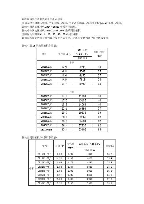
谷轮直通车经营的谷轮压缩机系列有:美国谷轮半封闭压缩机、谷轮双极压缩机、谷轮冷冻涡旋压缩机和谷轮低温ZF系列压缩机;谷轮空调涡旋压缩机ZR24~ZR380全系列压缩机;谷轮冷冻涡旋压缩机ZB15KQ~ZB11MC全系列压缩机;沈阳谷轮半封闭C、L、2S、3S、4S、6S系列压缩机。
直通车以强大的库存量为客户提供产品支持、优惠的价格为客户提供成本支持。
谷轮中温ZB涡旋压缩机参数表:谷轮空调压缩机ZR系列参数表:谷轮ZF系列低温压缩机参数表:型号HP 冷凝温度℃制冷量(W)10℃5℃0℃-5℃-10℃-15℃ZF06K4E 2 35 6950 5940 5040 4240 3550 2880 45 5960 5100 4330 3650 3050 2480 55 4910 4180 3550 3000 2520 2060ZF09K4E 3 35 9530 8130 6910 5820 4870 4100 45 8170 6970 5920 5000 4180 3550 55 6720 5730 4870 4120 3440 2900ZF11K4E 3.5 35 11700 10100 8550 7220 6050 5080 45 10200 8670 7370 6220 5210 4370 55 8400 7160 6050 5100 4260 3590ZF13K4E 4 35 12800 11300 9810 8420 7100 6030 45 11700 10100 8610 7250 6010 5120 55 9850 8320 6950 5780 4770 4070ZF15K4E 5 35 16800 14400 12200 10300 8650 7290 45 14500 12400 10500 88400 7390 6260 55 11900 10100 8570 7200 6030 5080ZF18K4E 6 35 17000 14400 12200 10200 8550 7250 45 14700 12500 10500 8840 7390 6240 55 12000 10200 8610 7250 6050 5120型号马力HP缸数排气量m3/h外形尺寸mm长宽高净重KG谷轮柔性涡旋压缩机在多方面显示出了它独特的优越性,高能效比,低噪音,高可靠性,低的系统设计成本和运行成本。
谷轮压缩机

高真空运行保护
不允许作为系统抽真空用
只允许在运行范围内作抽空循环用 长时间低压运行会造成涡旋盘和轴承的损坏
当压缩比达到10:1左右时,压缩机会自动卸载(浮动密封动作), 从而防止产生电弧。
压缩机参数测量
压缩机吸气温度和压力:位于四通阀至压缩机吸气管之间的管路 上
压缩机排气温度和压力:位于四通阀至压缩机排气管之间的管路 上
内置电机保护器
可同时感应温度和电流 单相:对运行绕组和启动绕组均起保护。有故障时,保护器切断 公共端 三相:连在Y型电机中心,对三相均起保护。只要其中一相有故 障,保护器同时切断三相,包括缺相情况 由于是自动复位,我们建议增加一个电流互感器来帮助确定是否 压缩机已内保动作 如果希望另加过流保护器且在压缩机内保之前动作,设定值应界 入Imax和MCC之间
膨胀阀系统
过热度控制好,整体能效高,选择泄孔型将有助于启 动,但价格高,感温包位置较为关键
膨胀阀系统的负荷调节能力好,单冷热泵都适合
低环境温度制热也建议使用一个较制冷小的膨胀阀
热泵应用时通过试验来确定制热可允许的最低环温
热泵应用建议配合使用高压储液器和分液头
高压储液器结构
高压储液器功能
谷轮柔性涡旋压缩机应用
压缩机型号
型号举例
ZR144KC-TFD-522
ZR:空调涡旋 匹数:144/12 = 12匹 冷量:144000x(5/6)x0.3 = 36000W(ARI工况) TFD:三相+内置保护+380V/50Hz 522:焊口、四脚、带接地螺钉
谷轮ZW系列(中间补气涡旋)压缩机应用指南

AE4-1381May 2011ZW21 to ZW61KAE and ZW30 to ZW61KSECopeland Scroll® Water Heating CompressorsTABLE OF CONTENTSSection Page Section PageIntroduction (2)ZW**KA Application (2)ZW**KS ApplicationVapour Injection - Theory of Operation (2)Heat Exchanger and Expansion Device Sizing (3)Flash Tank Application (3)Intermediate Pressure and Vapour Injection Superheat (3)Application ConsiderationsHigh Pressure Cut-Out (4)Low Pressure Cut-Out (4)Discharge Temperature Protection (4)Discharge Temperature Control (4)Discharge Mufflers (4)Oil Dilution and Compressor Cooling (4)Electrical Considerations (5)Brazing and Vapour Injection Line (5)Low Ambient Cut-Out (5)Internal Pressure Relief Valve (5)Internal Temperature Protection (5)Quiet Shutdown (5)Discharge Check Valve (5)Motor Protector (5)Accumulators (5)Screens (6)Crankcase Heat-Single Phase (6)Crankcase Heat-Three Phase (6)Pump Down Cycle (6)Minimum Run Time (6)Reversing Valves (6)Oil Type (7)System Noise & Vibration (7)Single Phase Starting Characteristics (7)PTC Start Components (7)Electrical Connections (7)Deep Vacuum Operation (7)Shell Temperature (7)Suction & Discharge Fittings (7)Three Phase Scroll Compressors (8)Brief Power Interruptions ..........................................8Assembly Line ProceduresInstalling the Compressor (8)Assembly Line Brazing Procedure (8)Pressure Testing (8)Assembly Line System Charging Procedure (8)High Potential (AC Hipot) Testing (9)Unbrazing System Components (9)Service ProceduresCopeland Scroll Functional Check (9)Compressor Replacement After Motor Burn (10)Start Up of a New or Replacement Compressor (10)FiguresBrief Product Overview (11)ZW21KAE Envelope (R-134a) (11)ZWKAE Envelope (R-407C, Dew Point) (12)ZWKA Envelope (R-22) (12)ZWKS Envelope (R-22) (13)ZWKSE Envelope (R-407C, Dew Point) (13)Heat Pump with Vapour Injection – EXV Control (14)Heat Exchanger Schematic (14)Heat Pump with Flash Tank (15)Possible Flash Tank Configuration (15)Oil Dilution Chart (16)Crankcase Heater (17)Compressor Electrical Connection (17)Scroll Tube Brazing (17)How a Scroll Works (18)IntroductionThe ZW**KA and ZW**KS Copeland Scroll®compressors are designed for use in vapour compression heat pump water heating applications. Typical model numbers include ZW30KA-PFS and ZW61KSE-TFP. This bulletin addresses the specifics of water heating in the early part and deals with the common characteristics and general application guidelines for Copeland Scroll compressors in the later sections. Operating principles of the scroll compressor are described in Figure 15 at the end of this bulletin.As the drive for energy efficiency intensifies, water heating by fossil-fueled boilers and electric elements is being displaced by vapour compression heat pumps. Emerson Climate Technologies has developed two lines of special water heater compressors to meet the requirements of this demanding application. ZW**KA compressors are designed for lighter duty applications where the ambient temperature does not fall below 0°C and where lower water temperatures can be accepted as the ambient temperature falls. ZW**KS compressors are equipped with a vapour injection cycle which allows reliable operation in cold climates with significantly enhanced heating capacity, higher efficiency, and minimal requirement to reduce water outlet temperatures. Figure 1gives a brief product overview.Water heating is characterized by long operating hours at both high load and high compression ratios. Demand for hot water is at its highest when ambients are low and when conventional heat pump capacity falls off. On the positive side, the system refrigerant charge is usually small, so the risk to the compressor from dilution and flooded starts will usually be lower than in split type air-to-air heat pumps.Water heaters must operate in a wide range of ambient temperatures, and many systems will require some method of defrost. Some systems such as Direct Heating, Top Down Heating or Single Pass Heating operate at a constant water outlet temperature with variable water flow. Others such as Recirculation Heating, Cyclic Heating or Multipass Heating use constant water flow with the water outlet and inlet temperatures both rising slowly as the storage tank heats up. Both system types need to cope with reheating a tank where the hot water has been partially used, and reheating to the setpoint temperature is required. More complex systems deliver water at relatively low temperatures for under-floor heating circuits and are switched over to sanitary water heating a few times per day to provide higher temperature water for sanitary use. In addition, some countries have specific water temperature requirements for legionella control.ZW**KA ApplicationThe application envelopes for ZW**KA compressors are shown in Figures 2 - 4.Appropriate system hardware and control logic must be employed to ensure that the compressor is always operating within the envelope. Small short-term excursions outside the envelope are acceptable at the time of defrost when the load on the compressor is low. Operation with suction superheat of 5 -10K is generally acceptable except at an evaporating tem-perature above 100C when a minimum superheat of 10K is required.ZW**KS ApplicationThe ZW**KS* vapour-injected scroll compressors differ from ZW**KA models in many important details:• Addition of vapour injection• Significantly different application envelopes• Some differences in locked rotor amps (LRA), maximum continuous current (MCC), andmaximum operating current (MOC) – seenameplatesThe application envelopes for ZW**KS compressors are shown in Figures 5 and 6.Vapour Injection – Theory of Operation Operation with vapour injection increases the capacity of the outdoor coil and in turn the capacity and efficiency of the system – especially in low ambient temperatures. A typical schematic is shown in Figure 7. A heat exchanger is added to the liquid line and is used to cool the liquid being delivered to the heating expansion device. Part of the liquid refrigerant flow is flashed through an expansion valve on the evaporator side of the heat exchanger at an intermediate pressure and used to subcool the main flow of liquid to the main expansion device. Vapour from the liquid evaporating at intermediate pressure is fed to the vapour injection port on the ZW**KS compressor. This refrigerant is injected into the mid-compression cycle of the scroll compressor and compressed to discharge pressure. Heating capacity is increased, because low temperature liquid with lower specific enthalpy supplied to the outdoor coil increases the amount of heat that can be absorbed from the ambient air. Increased heat absorbed from the ambient increases the system condensing temperature and in turn the compressor power input. The increase in power inputalso contributes to the improvement in the overall heating capacity.Vapour Injection can be turned on and off by the addition of an optional solenoid valve on the vapour injection line on systems using a thermostatic expansion valve. Alternatively, an electronic expansion valve can be used to turn vapour injection on and off and to control the vapour injection superheat. A capillary tube is not suitable for controlling vapour injection.The major advantage of the electronic expansion valve is that it can be used to optimise the performance of the system and at the same time control the discharge temperature by injecting “wet vapour” at extreme operating conditions.The configurations and schematics shown are for reference only and are not applicable to every system. Please consult with your Emerson Application Engineer.Heat Exchanger and Expansion Device Sizing Various heat exchanger designs have been used successfully as subcoolers. In general they should be sized so that the liquid outlet temperature is less than 5K above the saturated injection temperature at the customer low temperature rating point. At very high ambient temperatures, it will normally be beneficial to turn vapour injection off to limit the load on the compressor motor. Application Engineering Bulletin AE4-1327 and Emerson Climate Technologies Product Selection Software can be used to help size the subcooling heat exchanger and thermal expansion valves, but selection and proper operation must be checked during development testing. Plate type subcoolers must be installed vertically with the injection expansion device connected at the bottom through a straight tube at least 150mm long to ensure good liquid distribution. See the schematic in Figure 8. Flash Tank ApplicationA possible flash tank configuration is shown in Figure9. This particular configuration is arranged to have flow through the flash tank and expansion devices in heating, and it bypasses the tank in defrost mode. The flash tank system works by taking liquid from the condenser and metering it into a vessel through a high-to-medium pressure expansion device. Part of the liquid boils off and is directed to the compressor vapour injection port. This refrigerant is injected into the mid-compression cycle of the scroll compressor and compressed to discharge pressure. The remaining liquid is cooled, exits from the bottom of the tank at intermediate pressure, and flows to the medium-to-low pressure expansion device which feeds the outdoor coil. Low temperature liquid with lower specific enthalpy increases the capacity of the evaporator without increasing mass flow and system pressure drops.Recommended tank sizing for single compressor application in this size range is a minimum of 200 mm high by 75 mm in diameter with 3/8 in. (9.5mm) tubing connections, although it is possible to use a larger tank to combine the liquid/vapour separation and receiver functions in one vessel. A sight tube (liquid level gauge) should be added to the tank for observation of liquid levels during lab testing. See schematic diagram Figure 10 for clarification.It is important to maintain a visible liquid refrigerant level in the tank under all operating conditions. Ideally the liquid level should be maintained in the 1/3 to 2/3 full range.Under no circumstances should the level drop to empty or rise to a full tank. As the tank level rises, liquid droplets tend to be swept into the vapour line leading to “wet” vapour injection. Although this can be useful for cooling a hot compressor, the liquid quantity cannot be easily controlled. Compressor damage is possible if the tank overflows. If liquid injection is required for any reason, it can be arranged as shown in Figures 7 and 9.Since liquid leaves the tank in a saturated state, any pressure drop or temperature rise in the line to the medium-to-low pressure expansion device will lead to bubble formation. Design or selection of the medium-to-low pressure expansion device requires careful attention due to the possible presence of bubbles at the inlet and the low pressure difference available to drive the liquid into the evaporator. An electronic expansion valve is the preferred choice. Intermediate Pressure and Vapour Injection SuperheatPressure in the flash tank cannot be set and is a complex function of the compressor inlet condition and liquid condition at the inlet of the high-to-medium pressure expansion device. However, liquid level can be adjusted, which in turn will vary the amount of liquid subcooling in the condenser (water to refrigerant heat exchanger) and vary the injection pressure. Systems with low condenser subcooling will derive the biggest gains by the addition of vapour injection. Systems operating with high pressure ratios will show the largest gains when vapour injection is applied. Such systems will have higher vapour pressure and higher injectionmass flow. Intermediate pressures in flash tank and heat exchanger systems should be very similar unless the subcooling heat exchanger is undersized and there is a large temperature difference between the evaporator and the liquid sides. Vapour exiting a flash tank will be saturated and may pick up 1 - 2K superheat in the vapour line to the compressor. Vapour injection superheat cannot be adjusted on flash tank systems. Heat exchanger systems will be at their most efficient when the vapour injection superheat is maintained at approximately 5K.APPLICATION CONSIDERATIONSHigh Pressure Cut OutIf a high pressure control is used with these compressors, the recommended maximum cut out settings are listed in Figure 1. The high pressure control should have a manual reset feature for the highest level of system protection. It is not recommended to use the compressor to test the high pressure switch function during the assembly line test.Although R-407C runs with higher discharge pressure than R-22, a common setting can be used. The cutout settings for R-134a are much lower, and the switches must be selected or adjusted accordingly.Low Pressure Cut OutA low pressure cut out is an effective protection against loss of charge or partial blockage in the system. The cut out should not be set more than 3 - 5K equivalent suction pressure below the lowest operating point in the application envelope. Nuisance trips during defrost can be avoided by ignoring the switch until defrost is finished or by locating it in the line between the evaporator outlet and the reversing valve. This line will be at discharge pressure during defrost. Recommended settings are given in Figure 1. Discharge Temperature ProtectionAlthough ZW compressors have an internal bi-metal Therm-O-Disc®(TOD) on the muffler plate, external discharge temperature protection is recommended for a higher level of protection and to enable monitoring and control of vapour injection on ZW**KS* models. The protection system should shut down the compressor when the discharge line temperature reaches 125°C. In low ambient operation, the temperature difference between the scroll center and the discharge line is significantly increased, so protection at a lower discharge temperature, e.g. 120°C when the ambient is below 0°C, will enhance system safety. For the highest level of system protection, the discharge temperature control should have a manual reset feature. The discharge sensor needs to be well insulated to ensure that the line temperature is accurately read. The insulation material must not deteriorate over the expected life of the unit.Discharge Temperature ControlSome systems use an electronic expansion valve to control the vapour injection superheat and a thermistor to monitor the discharge temperature. This combination allows the system designer to inject a small quantity of liquid to keep the discharge temperature within safe limits and avoid an unnecessary trip. Liquid injection should begin at approximately 115°C and should be discontinued when the temperature falls to 105°C. Correct functioning of this system should be verified during system development. It is far preferable to use liquid injection into the vapour injection port to keep the compressor cool rather than inject liquid into the compressor suction which runs the risk of diluting the oil and washing the oil from the moving parts. If some operation mode requires liquid injection but without the added capacity associated with “wet” vapour injection, a liquid injection bypass circuit can be arranged as shown in Figures 7 and 9.Caution: Although the discharge and oil temperature are within acceptable limits, the suction and discharge pressures cannot be ignored and must also fall within the approved application envelope.Discharge MufflersDischarge mufflers are not normally required in water heaters since the refrigerant does not circulate within the occupied space.Oil Dilution and Compressor CoolingThe oil temperature diagram shown in Figure 11is commonly used to make a judgment about acceptable levels of floodback in heat pump operation. Systems operating with oil temperatures near the lower limit line are never at their most efficient. Low ambient heating capacity and efficiency will both be higher if floodback is eliminated and the system runs with 1 - 5K suction superheat. Discharge temperature can be controlled by vapour injection, “wet” vapour injection, or even liquid injection if necessary. In this situation, the oil temperature will rise well into the safe zone, and the compressor will not be at risk of failure from diluted oil. The oil circulation rate will also be reduced as crankcase foaming disappears. Special care needs to be taken at the end of defrost to ensure that the compressor oil is not unacceptably diluted. The system will resume heating very quickly and bearing loads willincrease accordingly, so proper lubrication must be ensured.Electrical ConsiderationsMotor configuration and protection are similar to those of standard Copeland Scroll compressors. In some cases, a larger motor is required in the ZW**KS* models to handle the load imposed by operating with vapour injection. Wiring and fuse sizes should be reviewed accordingly.Brazing the Vapour Injection LineThe vapour injection connection is made from copper coated steel, and the techniques used for brazing the suction and discharge fittings apply to this fitting also. Low Ambient Cut-OutA low ambient cut-out is not required to limit heat pump operation with ZW**KS compressors. Water heaters using ZW**KA compressors must not be allowed to run in low ambients since this configuration would run outside of the approved operating envelope causing overheating or excessive wear. A low ambient cut-out should be set at 0°C for ZW**KA modelsIn common with many Copeland Scroll compressors, ZW models include the features described below: Internal Pressure Relief (IPR) ValveAll ZW compressors contain an internal pressure relief valve that is located between the high side and the low side of the compressor. It is designed to open when the discharge-to-suction differential pressure exceeds 26 - 32 bar. When the valve opens, hot discharge gas is routed back into the area of the motor protector to cause a trip.Internal Temperature ProtectionThe Therm-O-Disc® or TOD is a temperature-sensitive snap disc device located on the muffler plate between the high and low pressure sides of the compressor. It is designed to open and route excessively hot discharge gas back to the motor protector. During a situation such as loss of charge, the compressor will be protected for some time while it trips the protector. However, as refrigerant leaks out, the mass flow and the amperage draw are reduced and the scrolls will start to overheat.A low pressure control is recommended for loss of charge protection in heat pumps for the highest level of system protection. A cut out setting no lower than 2.5 bar for ZW**KA* models and 0.5 bar for ZW**KS* models is recommended. The low pressure cut-out, if installed in the suction line to the compressor, can provide additional protection against an expansion device failed in the closed position, a closed liquid line or suction line service valve, or a blocked liquid line screen, filter, orifice, or TXV. All of these can starve the compressor for refrigerant and result in compressor failure. The low pressure cut-out should have a manual reset feature for the highest level of system protection. If a compressor is allowed to cycle after a fault is detected, there is a high probability that the compressor will be damaged and the system contaminated with debris from the failed compressor and decomposed oil.If current monitoring to the compressor is available, the system controller can take advantage of the compressor TOD and internal protector operation. The controller can lock out the compressor if current draw is not coincident with the contactor energizing, implying that the compressor has shut off on its internal protector. This will prevent unnecessary compressor cycling on a fault condition until corrective action can be taken.Quiet Shut downAll scrolls in this size range have a fast acting valve in the center of the fixed scroll which provides a very quiet shutdown solution. Pressure will equalize internally very rapidly and a time delay is not required for any of the ZW compressors to restart. Also refer to the section on “Brief Power Interruption”. Discharge Check ValveA low mass, disc-type check valve in the discharge fitting of the compressor prevents the high side, high pressure discharge gas from flowing rapidly back through the compressor. This check valve was not designed to be used with recycling pump down because it is not entirely leak-proof.Motor ProtectorConventional internal line break motor protection is provided. The protector opens the common connection of a single-phase motor and the center of the Y connection on three-phase motors. The three-phase protector provides primary single-phase protection. Both types of protectors react to current and motor winding temperature.AccumulatorsThe use of accumulators is very dependent on the application. The scroll’s inherent ability to handle liquid refrigerant during occasional operating flood back situations often makes the use of an accumulator unnecessary in many designs. If flood back is excessive, it can dilute the oil to such an extent thatbearings are inadequately lubricated, and wear will occur. In such a case, an accumulator must be used to reduce flood back to a safe level that the compressor can handle.In water heaters, floodback is likely to occur when the outdoor coil frosts. The defrost test must be done at an outdoor ambient temperature of around 0°C in a high humidity environment. Liquid floodback must be monitored during reversing valve operation, especially when coming out of defrost. Excessive floodback occurs when the sump temperature drops below the safe operation line shown in Figure 11 for more than 10 seconds.If an accumulator is required, the oil return orifice should be 1 - 1.5mm in diameter depending on compressor size and compressor flood back results. Final oil return hole size should be determined through testing. ScreensScreens with a mesh size finer than 30 x 30 (0.6mm openings) should not be used anywhere in the system with these compressors. Field experience has shown that finer mesh screens used to protect thermal expansion valves, capillary tubes, or accumulators can become temporarily or permanently plugged with normal system debris and block the flow of either oil or refrigerant to the compressor. Such blockage can result in compressor failure.Crankcase Heater - Single PhaseCrankcase heaters are not required on single phase compressors when the system charge is not over 120% of the limit shown in Figure 1. A crankcase heater is required for systems containing more than 120% of the compressor refrigerant charge limit listed in Figure 1. This includes long line length systems where the extra charge will increase the standard factory charge above the 120% limit.Experience has shown that compressors may fill with liquid refrigerant under certain circumstances and system configurations, notably after longer off cycles when the compressor has cooled. This may cause excessive start-up clearing noise, or the compressor may lock up and trip on the protector several times before starting. The addition of a crankcase heater will reduce customer noise and light dimming complaints since the compressor will no longer have to clear out liquid during startup. Figure 12lists the crankcase heaters recommended for the various models and voltages.Crankcase Heat – Three-PhaseA crankcase heater is required for three-phase compressors when the system charge exceeds the compressor charge limit listed in Figure 1and an accumulator cannot be piped to provide free liquid drainage during the off cycle.Pump Down CycleA pump down cycle for control of refrigerant migration is not recommended for scroll compressors of this size. If a pump down cycle is used, a separate external check valve must be added.The scroll discharge check valve is designed to stop extended reverse rotation and prevent high-pressure gas from leaking rapidly into the low side after shut off. The check valve will in some cases leak more than reciprocating compressor discharge reeds, normally used with pump down, causing the scroll compressor to cycle more frequently. Repeated short-cycling of this nature can result in a low oil situation and consequent damage to the compressor. The low-pressure control differential has to be reviewed since a relatively large volume of gas will re-expand from the high side of the compressor into the low side on shut down. Minimum Run TimeThere is no set answer to how often scroll compressors can be started and stopped in an hour, since it is highly dependent on system configuration. Other than the considerations in the section on Brief Power Interruptions, there is no minimum off time. This is because scroll compressors start unloaded, even if the system has unbalanced pressures. The most critical consideration is the minimum run time required to return oil to the compressor after startup.Since water heaters are generally of compact construction, oil return and short cycling issues are rare. Oil return should not be a problem unless the accumulator oil hole is blocked.Reversing ValvesSince Copeland Scroll compressors have very high volumetric efficiency, their displacements are lower than those of comparable capacity reciprocating compressors. As a result, Emerson recommends that the capacity rating on reversing valves be no more than 2 times the nominal capacity of the compressor with which it will be used in order to ensure proper operation of the reversing valve under all operating conditions.The reversing valve solenoid should be wired so that the valve does not reverse when the system isshut off by the operating thermostat in the heating or cooling mode. If the valve is allowed to reverse at system shutoff, suction and discharge pressures are reversed to the compressor. This results in pressures equalizing through the compressor which can cause the compressor to slowly rotate until the pressures equalize. This condition does not affect compressor durability but can cause unexpected sound after the compressor is turned off.Oil TypeThe ZW**K* compressors are originally charged with mineral oil. A standard 3GS oil may be used if the addition of oil in the field is required. See the compressor nameplate for original oil charge. A complete recharge should be ~100 ml less than the nameplate value.ZW**K*E are charged with POE oil. Copeland 3MAF or Ultra 22 CC should be used if additional oil is needed in the field. Mobil Arctic EAL22CC, Emkarate RL22, Emkarate 32CF and Emkarate 3MAF are acceptable alternatives. POE oil is highly hygroscopic, and the oil should not be exposed to the atmosphere except for the very short period required to make the brazing connections to the compressor.System Noise and VibrationCopeland Scroll compressors inherently have low sound and vibration characteristics, but the characteristics differ in some respects from those of reciprocating or rotary compressors. The scroll compressor makes both a rocking and a torsional motion, and enough flexibility must be provided to prevent vibration transmission into any lines attached to the unit. This is usually achieved by having tubing runs at least 30cm long parallel to the compressor crankshaft and close to the shell. ZW compressors are delivered with rubber grommets to reduce vibration transmission to the system baseplate.Single Phase Starting CharacteristicsStart assist devices are usually not required, even if a system utilizes non-bleed expansion valves. Due to the inherent design of the Copeland Scroll, the internal compression components always start unloaded even if system pressures are not balanced. In addition, since internal compressor pressures are always balanced at startup, low voltage starting characteristics are excellent for Copeland Scroll compressors. Starting current on any compressor may result in a significant “sag” in voltage where a poor power supply is encountered. The low starting voltage reduces the starting torque of the compressor and subsequently increases the start time. This could cause light dimming or a buzzing noise where wire is pulled through conduit. If required, a start capacitor and potential relay can be added to the electrical circuit. This will substantially reduce start time and consequently the magnitude and duration of both light dimming and conduit buzzing.PTC Start ComponentsFor less severe voltage drops or as a start boost, solid state Positive Temperature Coefficient devices rated from 10 to 25 ohms may be used to facilitate starting for any of these compressors.Electrical ConnectionThe orientation of the electrical connections on the Copeland Scroll compressors is shown in Figure 13 and is also shown on the wiring diagram on the top of the terminal box cover.Deep Vacuum OperationScrolls incorporate internal low vacuum protection and will stop pumping (unload) when the pressure ratio exceeds approximately 10:1. There is an audible increase in sound when the scrolls start unloading. This feature does not prevent overheating and destruction of the scrolls, but it does protect the power terminals from internal arcing.Copeland Scroll compressors(as with any refrigerant compressor) should never be used to evacuate a refrigeration or air conditioning system. The scroll compressor can be used to pump down refrigerant in a unit as long as the pressures remain within the operating envelope. Prolonged operation at low suction pressures will result in overheating of the scrolls and permanent damage to the scroll tips, drive bearings and internal seal. (See AE24-1105 for proper system evacuation procedures.)Shell TemperatureCertain types of system failures, such as condenser or evaporator blockage or loss of charge, may cause the top shell and discharge line to briefly but repeatedly reach temperatures above 175ºC as the compressor cycles on its internal protection devices. Care must be taken to ensure that wiring or other materials, which could be damaged by these temperatures, do not come in contact with these potentially hot areas. Suction and Discharge FittingsCopeland Scroll compressors have copper plated steel suction and discharge fittings. These fittings are far more rugged and less prone to leaks than。
沈阳谷轮压缩机样本

曲轴箱加热器功率(瓦) Crankcase Heater Power (W)
长(L)
Length
宽(W)
Width
高(不带风扇) (H)
Height (without fan)
高(带风扇) (J)
Height (with fan)
底脚安装尺寸(A)×(B)
Installation Size of Footing
TFC:200-3-50/60 内藏式保护器
Inner Protector
TWC:200-3-50/60 电子式保护器 Electronic Protector
TFM:380/400-3-50 内藏式保护器
Inner Protector
TWM:380/400-3-50 电子式保护器 Electronic Protector
R22
50Hz
-25 5300 2625 4410 2800 3600 3000 7270 3350 6390 3650 4880 3990 10700 5200 9340 5750 7890 6000 15700 7400 14180 8100 12790 8800
-30 3840 2300
5350 2950
最大工作电流(MCC)(安培)Max.Working Current(MCC)(A)
TFC和TWC电机
TFC and TWC Motor
TFM和TWM电机
TFM and TWM Motor
接管尺寸(毫米)
Size of Pipe (mm)
排气阀接管
Exhaust Valve Pipe
吸气阀接管
Suction Valve Pipe
91 100
谷轮压缩机参照表

6
运行范围
冷凝温度°C
75
70
65
60
55
50
45
40
35 30
25
20 15
10
5
0 -40 -35 -30 -25 -20 -15 -10 -5 0 5 10 15 20 25
蒸发温度°C
ZR18 to ZR81KC (R22) ZR/VR84 to ZR/VR190KC/KS (R22)
堵转电流 (A)
53.0 52.9 52.9 66.0 100.0 100.0 114.0 97.0 114.0 114.0 114.0 150.0 150.0
噪音 声功率 (dBA)
63.0 63.0 63.0 68.0 66.0 68.0 68.0 68.0 68.0 68.0 68.0 71.0 72.0
制冷能力
(W)
6,250 6,750 7,350 7,900 8,200 8,900 9,850 10,250 11,200 11,550 11,850 14,950 16,700
(Btu/h)
21,400 23,000 25,000 27,000 28,000 30,300 33,600 35,000 38,200 39,400 40,500 51,000 57,000
60 Hz
单相 三相 双机并联 kW 制冷容量
0
20 40 60 80 100 120 140 160 180 200 220 240 260 280 300 320 340 360 380 400 420
7
技术参数
220-240V; 50Hz, 1 Phase
R22
谷轮涡旋机组参数性能样本
油充注量(升)
回气管接管外径
液管接管外径
重量(公斤) 额定运行电流RLA(A)(安培)
TFD 380/420-3-50Hz 启动电流LRA(A)(安培)
TFD
ZX 15 KC TFD ZX 21 KC TFD ZX 30 KC TFD ZX 38 KC TFD ZX 45 KC TFD ZX 51 KC TFD ZX 15 KCE TFD ZX 21 KCE TFD ZX 30 KCE TFD ZX 38 KCE TFD ZX 45 KCE TFD ZX 51 KCE TFD
50 Hz
-5 5.08 4.68 3.64 3.34 6.89 6.65 6.66 6.43 8.70 8.01 7.36 6.69 12.31 11.43 10.32 9.37 13.30 12.58 11.55 10.74 15.07 13.86 12.47 11.38
0 5.79 5.29 4.16 3.81 8.24 7.95 7.97 7.81 10.08 9.20 8.40 7.61 13.93 13.10 11.98 10.98 15.69 14.72 13.48 12.57 17.76 16.20 14.54 13.32
3
ZX 系列 Series
外形尺寸 Dimensions
ZX0200, 0300, 0400
ZX0500, 0600, 0750
型号说明 Model Nomenclature
相数
或 460
50Hz 60Hz
供
(L)
视
(Q)
(R)
(T)
(O)
(P)
(I)
(B)
4
GP 系列 Series
谷轮压缩机参数表
谷轮直通车经营的谷轮压缩机系列有:美国谷轮半封闭压缩机、谷轮双极压缩机、谷轮冷冻涡旋压缩机和谷轮低温ZF系列压缩机;谷轮空调涡旋压缩机ZR24~ZR380全系列压缩机;谷轮冷冻涡旋压缩机ZB15KQ~ZB11MC全系列压缩机;沈阳谷轮半封闭C、L、2S、3S、4S、6S系列压缩机。
直通车以强大的库存量为客户提供产品支持、优惠的价格为客户提供成本支持。
谷轮中温ZB涡旋压缩机参数表:谷轮空调压缩机ZR系列参数表:谷轮ZF系列低温压缩机参数表:型号HP 冷凝温度℃制冷量(W)10℃5℃0℃-5℃-10℃-15℃ZF06K4E235695059405040424035502880 45596051004330365030502480 55491041803550300025202060ZF09K4E335953081306910582048704100 45817069705920500041803550 55672057304870412034402900ZF11K4E 3511700101008550722060505080 451020086707370622052104370 55840071606050510042603590ZF13K4E43512800113009810842071006030 4511700101008610725060105120 55985083206950578047704070ZF15K4E5351680014400122001030086507290 451450012400105008840073906260 5511900101008570720060305080ZF18K4E6351700014400122001020085507250 45147001250010500884073906240 5512000102008610725060505120型号马力HP缸数排气量m3/h外形尺寸mm长宽高净重KG谷轮柔性涡旋压缩机在多方面显示出了它独特的优越性,高能效比,低噪音,高可靠性,低的系统设计成本和运行成本。
古轮应用工程手册
4-13034-1303 应用工程手册AE-1303-R4 版本:2001年3月谷轮柔性涡旋压缩机ZR84KC ~ ZR144KC应用指南简介本手册叙述了7至12冷吨R22和R407C SUMMIT 谷轮涡旋压缩机的运行特性、设计特点与应用需求,典型型号为ZR84K C-T F5和ZR144KC-TF D。
如需得到更多详情,请上网页www.cop ela nd-cor p.c om查询产品资料。
谷轮涡旋压缩机的工作原理在应用工程手册AE-1312里说明。
以下描述的SUM MIT压缩机操作性能和设计特点有一些是与小型的谷轮涡旋压缩机不同的。
SUMMIT涡旋压缩机是为空调和热泵而设计的,在工作范围内的其它工况同样也适用(见图2显示的运行范围)。
为了提高电机效率和电机冷却,吸气口安置在壳体较低处以使回气通过电机。
因为吸气口位置较低,必须注意在安装和移动压缩机时应保持直立,否则油可能从此处溅出。
这在以后的“压缩机搬运”中还要提及。
关于柔性涡旋压缩机的工作原理请查阅工程应用手册AE 4-1280。
应用注意事项谷轮涡旋压缩机在应用特性上与传统的活塞式压缩机有所不同,具体如下:压缩机搬运因为油可能从机壳上位置较低的吸气连接口喷出,在压缩机安装到系统中之前不应拔掉吸气口的塞子。
如果可能的话,装运时应保持压缩机直立。
在拔掉吸气口塞子之前应先拔掉排气口塞子,以使机壳内的干燥压缩空气释放。
这样可避免冷冻油溅到吸气管表面而造成的焊接困难。
镀铜吸气钢管在焊接前应进行清洗(见图5)。
不允许有任何物体(如扩管工具)伸进吸气管超过51mm(2i n),否则有可能会损坏吸气滤网或电机。
内置压力释放阀(I PR Val ve)SUMMIT柔性涡旋压缩机没有内置压力释放阀,为保证安全运行,在所有应用中都应配一个压力设置不超过 2.9MPa(表)(425psig)的高压保护器。
安全控制高压控制:因为这种压缩机没有内置压力释放阀,所以必须在系统中有一个压力设定值不超过2.9MP a(表) (425psig)的高压保护器。
谷轮压缩机规格书VR125KS-TFP-522
120 C (260) P
A
53500 7700 14.1
67500 7800 14.2
83500 102000 112000 123000 134000
7850 7900 7950 8000 8050
14.3
14.4
14.4
14.5
14.6
M
790
975 1190 1440 1570 1710 1860
3 50 10.4 380 342 418 110.0 19.2 2 2900 10.198 167.1 1027 29.1 135 61.3 MINERAL OIL 110 106 3253 3134 342 342 三相,感应式 135oC (275oF) 1.227 31 14074 75 3 <400 WITHOUT OIL 75 内置式电机保护器 527-0116-00 环氧树脂漆(黑色) 磷化表面处理 待定 待定 待定
5400 5500 5600 5700 5800
11.3
11.5
11.6
11.6
11.8
M
520
660
825 1020 1240 1480 1610 1750 1890
E
7.8
9.8
12.1
14.9
18.1
21.5
23.2
24.9
26.6
%
62.1
66.9
71
73.3
73
69.4
66.2
62
56.8
HCFC-22 COPELAND SCROLL? TFP 380-3-50
Condensing Temperature °F
(Sat Dew Pt Pressure, psig) Evaporating Temperature °F (Sat Dew Pt Pressure, psig)