RTC64613A英语资料
infineon 有源钳位
Page 21
Infineon‘s Latest Release
EiceDriver™ - 1ED020I12-F
Single Channel Gate Driver IC Galvanic Isolation Coreless Transformer Technology Driving IGBT/MOSFET up to 100A (1200V)
EiceDriver
Page 23
Isoaltion Definitions
Functional Insulation:
VDE 0884-10 Approved UL1577 Pending
Insulation between conductive parts which is necessary only for the proper functioning of the equipment. Basic Insulation: Insulation applied to live parts to provide basic protection against electric shock. Supplementary Insulation: Independent insulation applied in addition to basic insulation, in order to provide protection against shock in the event of a failure of basic insulation. Double Insulation: Insulation comprising both basic insulation and supplementary insulation. Reinforced Insulation: A single Insulation applied to live parts, which provides a degree of protection against electric shock equivalent to double insulation
锂电池规格书(中英文)

History of revision版本更改历史记录Contents 目录1.Scope 适用范围 32.Adopted Standard引用标准 33.Electrical Characteristics电气特性 34.Battery Performances Test Criterion 电池性能测试规范 35.1 Appearance 外观 35.2 Measurement Apparatus 测试设备 35.3 Testing Condition 测试条件 35.4 Reliability Test 可靠性测试 35.Shipment 运输 36.Storage 贮存 37.Package and Marking包装与标志 38.1 Package 包装 38.2 Marking 标志 38.Protection Circuit 保护电路 39.1 Schematic of the PCB 保护板原理图 39.2 PCM BOM9.3 PCM Parameter PCM参数 39.Outline Drawing 外形图纸 310.Appendix 附录 33.7 Instructions and Safety Requirement 使用说明和安全规程 33.7.1 Recommending Usage推荐使用事项 33.7.2 Hazard Warning危险警告 33.7.3 Warning 警告 33.7.4 Cautions 注意事项 310.2 Quality Evaluation Programme 质量评定 310.3 Environment Protection 环保要求 310.4 Others 其他事项 31.Scope 适用范围This description defines the general requirements for thebattery’s rating parameter, electrical requirement, safety requirement, environmental compatibility, test and judgment, usage instructions, safety regulation, quality evaluation and packaging, marking, storage,shipment and handling, which cellular phone battery with 523450AR-850mAh rechargeable battery cell, adapted for Digital products.本规格书描述电池之标称参数、电气特性、安全性能、环境适应性及其实验和判定、使用说明和安全规程、质量评定及包装、标志、贮存、运输等。
HD6435368S中文资料

OMC 932723248Hitachi Single-Chip MicrocomputerH8/534, H8/536HD6475348R, HD6435348RHD6475368R, HD6435368RHD6475348S, HD6435348SHD6475368S, HD6435368SHardware ManualADE-602-038BPrefaceThe H8/534 and H8/536 are high-performance single-chip Hitachi-original microcomputers, featuring a high-speed CPU with 16-bit internal data paths and a full complement of on-chip supporting modules. They are ideal microcontrollers for a wide variety of medium-scale devices, including both office and industrial equipment and consumer products.The CPU has a general-register architecture. Its instruction set is highly orthogonal and is optimized for fast execution of programs coded in the high-level C language. For further speed, the existing 10-MHz lineup has been extended to include high-speed versions that operate at16 MHz. Low-voltage versions that operate at 3 V and 2.7 V have also been developed.On-chip facilities include large RAM and ROM memories, numerous timers, serial I/O, an A/D converter, I/O ports, and other functions for compact implementation of high-performance application systems.H8/534 and H8/536 are available in both a ZTAT™version* with on-chip PROM, ideal for the early stages of production or for products with frequently-changing specifications, and a masked-ROM version suitable for volume production.This manual gives a hardware description of the H8/534 and H8/536. For details of the instruction set, refer to the H8/500 Series Programming Manual, which applies to all chips in the H8/500 Series.* ZTAT (Zero Turn-Around Time) is a trademark of Hitachi, Ltd.2ContentsSection 1 Overview1.1Features (1)1.2Block Diagram (5)1.3Pin Arrangements and Functions (6)1.3.1Pin Arrangement (6)1.3.2Pin Functions (9)Section 2 MCU Operating Modes and Address Space2.1Overview (23)2.2Mode Descriptions (24)2.3Address Space Map (25)2.3.1Page Segmentation (25)2.3.2Page 0 Address Allocations (26)2.4Mode Control Register (MDCR) (27)Section 3 CPU3.1Overview (31)3.1.1Features (31)3.1.2Address Space (32)3.1.3Register Configuration (33)3.2CPU Register Descriptions (34)3.2.1General Registers (34)3.2.2Control Registers (35)3.2.3Initial Register Values (40)3.3Data Formats (41)3.3.1Data Formats in General Registers (41)3.3.2Data Formats in Memory (42)3.4Instructions (44)3.4.1Basic Instruction Formats (44)3.4.2Addressing Modes (45)3.4.3Effective Address Calculation (47)3.5Instruction Set (50)3.5.1Overview (50)3.5.2Data Transfer Instructions (52)3.5.3Arithmetic Instructions (53)3.5.4Logic Operations (54)3.5.5Shift Operations (55)3.5.6Bit Manipulations (56)3.5.7Branching Instructions (57)3.5.8System Control Instructions (59)3.5.9Short-Format Instructions (62)3.6Operating Modes (62)3.6.1Minimum Mode (62)3.6.2Maximum Mode (63)3.7Basic Operational Timing (63)3.7.1Overview (63)3.7.2On-Chip Memory Access Cycle (64)3.7.3Pin States during On-Chip Memory Access (65)3.7.4Register Field Access Cycle (Addresses H'FE80 to H'FFFF) (66)3.7.5Pin States during Register Field Access (Addresses H'FE80 to H'FFFF) (67)3.7.6External Access Cycle (68)3.8CPU States (69)3.8.1Overview (69)3.8.2Program Execution State (71)3.8.3Exception-Handling State (71)3.8.4Bus-Released State (72)3.8.5Reset State (77)3.8.6Power-Down State (77)3.9Programming Notes (78)3.9.1Restriction on Address Location (78)Section 4 Exception Handling4.1Overview (79)4.1.1Types of Exception Handling and Their Priority (79)4.1.2Hardware Exception-Handling Sequence (80)4.1.3Exception Factors and Vector Table (80)4.2Reset (83)4.2.1Overview (83)4.2.2Reset Sequence (83)4.2.3Stack Pointer Initialization (84)4.3Address Error (87)4.3.1Illegal Instruction Prefetch (87)4.3.2Word Data Access at Odd Address (87)4.3.3Off-Chip Address Access in Single-Chip Mode (87)4.4Trace (88)4.5Interrupts (88)4.6Invalid Instruction (91)4.7Trap Instructions and Zero Divide (91)4.8Cases in Which Exception Handling is Deferred (91)4.8.1Instructions that Disable Interrupts (91)4.8.2Disabling of Exceptions Immediately after a Reset (92)4.8.3Disabling of Interrupts after a Data Transfer Cycle (92)4.9Stack Status after Completion of Exception Handling (93)4.9.1PC Value Pushed on Stack for Trace,Interrupts, Trap Instructions, and Zero Divide Exceptions (95)4.9.2PC Value Pushed on Stack for Address Error and InvalidInstruction Exceptions (95)4.10Notes on Use of the Stack (95)Section 5 Interrupt Controller5.1Overview (97)5.1.1Features (97)5.1.2Block Diagram (98)5.1.3Register Configuration (99)5.2Interrupt Types (99)5.2.1External Interrupts (99)5.2.2Internal Interrupts (101)5.2.3Interrupt Vector Table (102)5.3Register Descriptions (104)5.3.1Interrupt Priority Registers A to F (IPRA to IPRF) (104)5.3.2Timing of Priority Setting (105)5.4Interrupt Handling Sequence (105)5.4.1Interrupt Handling Flow (105)5.4.2Stack Status after Interrupt Handling Sequence (108)5.4.3Timing of Interrupt Exception-Handling Sequence (109)5.5Interrupts During Operation of the Data Transfer Controller (109)5.6Interrupt Response Time (112)Section 6 Data Transfer Controller6.1Overview (113)6.1.1Features (113)6.1.2Block Diagram (113)6.1.3Register Configuration (114)6.2Register Descriptions (115)6.2.1Data Transfer Mode Register (DTMR) (115)6.2.2Data Transfer Source Address Register (DTSR) (116)6.2.3Data Transfer Destination Register (DTDR) (116)6.2.4Data Transfer Count Register (DTCR) (116)6.2.5Data Transfer Enable Registers A to F (DTEA to DTEF) (117)6.3Data Transfer Operation (118)6.3.1Data Transfer Cycle (118)6.3.2DTC Vector Table (120)6.3.3Location of Register Information in Memory (122)6.3.4Length of Data Transfer Cycle (122)6.4Procedure for Using the DTC (124)6.5Example (125)Section 7 Wait-State Controller7.1Overview (127)7.1.1Features (127)7.1.2Block Diagram (128)7.1.3Register Configuration (128)7.2Wait-State Control Register (129)7.3Operation in Each Wait Mode (130)7.3.1Programmable Wait Mode (130)7.3.2Pin Wait Mode (131)7.3.3Pin Auto-Wait Mode (133)Section 8 Clock Pulse Generator8.1Overview (135)8.1.1Block Diagram (135)8.2Oscillator Circuit (135)8.3System Clock Divider (139)Section 9 I/O Ports9.1Overview (141)9.2Port 1 (144)9.2.1Overview (144)9.2.2Port 1 Registers (144)9.2.3Pin Functions in Each Mode (147)9.3Port 2 (150)9.3.1Overview (150)9.3.2Port 2 Registers (151)9.3.3Pin Functions in Each Mode (152)9.4Port 3 (153)9.4.1Overview (153)9.4.2Port 3 Registers (154)9.4.3Pin Functions in Each Mode (155)9.5Port 4 (156)9.5.1Overview (156)9.5.2Port 4 Registers (157)9.5.3Pin Functions in Each Mode (158)9.6Port 5 (159)9.6.1Overview (159)9.6.2Port 5 Registers (160)9.6.3Pin Functions in Each Mode (161)9.6.4Built-In MOS Pull-Up (163)9.7Port 6 (165)9.7.1Overview (165)9.7.2Port 6 Registers (166)9.7.3Pin Functions in Each Mode (170)9.7.4Built-In MOS Pull-Up (172)9.8Port 7 (173)9.8.1Overview (173)9.8.2Port 7 Registers (173)9.8.3Pin Functions (174)9.9Port 8 (177)9.9.1Overview (177)9.9.2Port 8 Registers (177)9.10Port 9 (178)9.10.1Overview (178)9.10.2Port 9 Registers (178)9.10.3Pin Functions (179)Section 10 16-Bit Free-Running Timers10.1Overview (183)10.1.1Features (183)10.1.2Block Diagram (184)10.1.3Input and Output Pins (185)10.1.4Register Configuration (186)10.2Register Descriptions (187)10.2.1Free-Running Counter (FRC)—H'FE92, H'FEA2, H'FEB2 (187)10.2.2Output Compare Registers A and B (OCRA and OCRB)—H'FE94and H'FE96, H'FEA4 and H'FEA6, H'FEB4 and H'FEB6 (188)10.2.3Input Capture Register (ICR)—H'FE98, H'FEA8, H'FEB8 (188)10.2.4Timer Control Register (TCR) (189)10.2.5Timer Control/Status Register (TCSR) (191)10.3CPU Interface (194)10.4Operation (196)10.4.1FRC Incrementation Timing (196)10.4.2Output Compare Timing (197)10.4.3Input Capture Timing (199)10.4.4Setting of FRC Overflow Flag (OVF) (201)10.5CPU Interrupts and DTC Interrupts (201)10.6Synchronization of Free-Running Timers 1 to 3 (202)10.6.1Synchronization after a Reset (202)10.6.2Synchronization by Writing to FRCs (202)10.7Sample Application (206)10.8Application Notes (206)Section 11 8-Bit Timer11.1Overview (213)11.1.1Features (213)11.1.2Block Diagram (214)11.1.3Input and Output Pins (215)11.1.4Register Configuration (215)11.2Register Descriptions (215)11.2.1Timer Counter (TCNT)—H'FED4 (215)11.2.2Time Constant Registers A and B(TCORA and TCORB)—H'FED2 and H'FED3 (216)11.2.3Timer Control Register (TCR)—H'FED0 (216)11.2.4Timer Control/Status Register (TCSR)—H'FED1 (218)11.3Operation (220)11.3.1TCNT Incrementation Timing (220)11.3.2Compare Match Timing (221)11.3.3External Reset of TCNT (223)11.3.4Setting of TCNT Overflow Flag (224)11.4CPU Interrupts and DTC Interrupts (224)11.5Sample Application (225)11.6Application Notes (226)Section 12 PWM Timer12.1Overview (233)12.1.1Features (233)12.1.2Block Diagram (233)12.1.3Input and Output Pins (234)12.1.4Register Configuration (235)12.2Register Descriptions (235)12.2.1Timer Counter (TCNT)—H'FEC2, H'FEC4, H'FECA (235)12.2.2Duty Register (DTR)—H'FEC1, H'FEC5, H'FEC9 (236)12.2.3Timer Control Register (TCR)—H'FEC0, H'FEC4, H'FEC8 (236)12.3Operation (238)12.4Application Notes (240)Section 13 Watchdog Timer13.1Overview (241)13.1.1Features (241)13.1.2Block Diagram (242)13.1.3Register Configuration (242)13.2Register Descriptions (243)13.2.1Timer Counter TCNT—H'FEEC (Write), H'FEED (Read) (243)13.2.2Timer Control/Status Register (TCSR)—H'FEEC (243)13.2.3Reset Control/Status Register (RSTCSR)—H'FF14 (Write), H'FF15 (Read) (245)13.2.4Notes on Register Access (246)13.3Operation (248)13.3.1Watchdog Timer Mode (248)13.3.2Interval Timer Mode (249)13.3.3Operation in Software Standby Mode (250)13.3.4Setting of Overflow Flag (250)13.3.5Setting of Watchdog Timer Reset (WRST) Bit (251)13.4Application Notes (252)Section 14 Serial Communication Interface14.1Overview (255)14.1.1Features (255)14.1.2Block Diagram (256)14.1.3Input and Output Pins (257)14.1.4Register Configuration (257)14.2Register Descriptions (258)14.2.1Receive Shift Register (RSR) (258)14.2.2Receive Data Register (RDR)—H'FEDD, H'FEF5 (258)14.2.3Transmit Shift Register (TSR) (258)14.2.4Transmit Data Register (TDR)—H'FEDB, H'FEF3 (259)14.2.5Serial Mode Register (SMR)—H'FED8, H'FEF0 (259)14.2.6Serial Control Register (SCR)—H'FEDA, H'FEF2 (261)14.2.7Serial Status Register (SSR)—H'FEDC, H'FEF4 (263)14.2.8Bit Rate Register (BRR)—H'FED9, H'FEF1 (265)14.3Operation (270)14.3.1Overview (270)14.3.2Asynchronous Mode (271)14.3.3Synchronous Mode (275)14.4CPU Interrupts and DTC Interrupts (279)14.5Application Notes (280)Section 15 A/D Converter15.1Overview (283)15.1.1Features (283)15.1.2Block Diagram (284)15.1.3Input Pins (285)15.1.4Register Configuration (285)15.2Register Descriptions (286)15.2.1A/D Data Registers (ADDR)—H'FEE0 to H'FEE7 (286)15.2.2A/D Control/Status Register (ADCSR)—H'FEE8 (287)15.2.3A/D Control Register (ADCR)—H'FEE9 (289)15.3CPU Interface (290)15.4Operation (291)15.4.1Single Mode (SCAN = 0) (291)15.4.2Scan Mode (SCAN = 1) (294)15.4.3Input Sampling Time and A/D Conversion Time (296)15.4.4External Triggering of A/D Conversion (297)15.5Interrupts and the Data Transfer Controller (298)Section 16 RAM16.1Overview (299)16.1.1Block Diagram (299)16.1.2Register Configuration (300)16.2RAM Control Register (RAMCR) (300)16.3Operation (300)16.3.1Expanded Modes (Modes 1, 2, 3, and 4) (300)16.3.2Single-Chip Mode (Mode 7) (301)Section 17 ROM17.1Overview (303)17.1.1Block Diagram (303)17.2PROM Mode (304)17.2.1PROM Mode Setup (304)17.2.2Socket Adapter Pin Arrangements and Memory Map (305)17.3H8/534 Programming (308)17.3.1Writing and Verifying (308)17.3.2Notes on Writing (311)17.4H8/536 Programming (312)17.4.1Writing and Verifying (312)17.4.2Notes on Programming (315)17.5Reliability of Written Data (317)17.6Erasing of Data (318)17.7Handling of Windowed Packages (319)Section 18 Power-Down State18.1Overview (321)18.2Sleep Mode (322)18.2.1Transition to Sleep Mode (322)18.2.2Exit from Sleep Mode (322)18.3Software Standby Mode (322)18.3.1Transition to Software Standby Mode (322)18.3.2Software Standby Control Register (SBYCR) (323)18.3.3Exit from Software Standby Mode (324)18.3.4Sample Application of Software Standby Mode (324)18.3.5Application Notes (325)18.4Hardware Standby Mode (325)18.4.1Transition to Hardware Standby Mode (325)18.4.2Recovery from Hardware Standby Mode (326)18.4.3Timing Sequence of Hardware Standby Mode (326)Section 19 E Clock Interface19.1Overview (327)Section 20 Electrical Specifications20.1Absolute Maximum Ratings (331)20.2Electrical Characteristics (331)20.2.1DC Characteristics (331)20.2.2AC Characteristics (340)20.2.3A/D Converter Characteristics (349)20.3MCU Operational Timing (350)20.3.1Bus Timing (351)20.3.2Control Signal Timing (354)20.3.3Clock Timing (355)20.3.4I/O Port Timing (357)20.3.516-Bit Free-Running Timer Timing (358)20.3.68-Bit Timer Timing (359)20.3.7Pulse Width Modulation Timer Timing (360)20.3.8Serial Communication Interface Timing (360)20.3.9A/D Trigger Signal Input Timing (361)Appendix A InstructionsA.1Instruction Set (363)A.2Instruction Codes (368)A.3Operation Code Map (379)A.4Instruction Execution Cycles (384)A.4.1Calculation of Instruction Execution States (384)A.4.2Tables of Instruction Execution Cycles (385)Appendix B Register FieldB.1Register Addresses and Bit Names (393)B.2Register Descriptions (398)Appendix C I/O Port Schematic DiagramsC.1Schematic Diagram of Port 1 (437)C.2Schematic Diagram of Port 2 (444)C.3Schematic Diagram of Port 3 (445)C.4Schematic Diagram of Port 4 (446)C.5Schematic Diagram of Port 5 (447)C.6Schematic Diagram of Port 6 (448)C.7Schematic Diagram of Port 7 (450)C.8Schematic Diagram of Port 8 (455)C.9Schematic Diagram of Port 9 (456)Appendix D Memory Maps (463)Appendix E Pin StatesE.1Port State of Each Pin State (465)E.2Pin States in Reset State (468)Appendix F Timing of Transition to and Recovery fromHardware Standby Mode (475)Appendix G Package Dimensions (476)Figures1-1Block Diagram (5)1-2Pin Arrangement (CP-84, Top View) (6)1-3Pin Arrangement (CG-84, Top View) (7)1-4Pin Arrangement (FP-80A, TFP-80C, Top View) (8)2-1H8/534 Memory Map in Each Operating Mode (28)2-2H8/536 Memory Map in Each Operating Mode (29)3-1CPU Operating Modes (32)3-2Registers in the CPU (33)3-3Stack Pointer (34)3-4Combinations of Page Registers with Other Registers (38)3-5Short Absolute Addressing Mode and Base Register (39)3-6On-Chip Memory Access Timing (64)3-7Pin States during Access to On-Chip Memory (65)3-8Register Field Access Timing (66)3-9Pin States during Register Field Access (67)3-10 (a)External Access Cycle (Read Access) (68)3-10 (b)External Access Cycle (Write Access) (69)3-11 Operating States (70)3-12State Transitions (71)3-13Bus-Right Release Cycle (During On-chip Memory Access Cycle) (73)3-14Bus-Right Release Cycle (During External Access Cycle) (74)3-15Bus-Right Release Cycle (During Internal CPU Operation) (75)4-1Types of Factors Causing Exception Handling (81)4-2Reset Vector (84)4-3Reset Sequence (Minimum Mode, On-Chip Memory) (85)4-4Reset Sequence (Maximum Mode, External Memory) (86)4-5Interrupt Sources (and Number of Interrupt Types) (90)5-1Interrupt Controller Block Diagram (98)5-2Interrupt Handling Flowchart (107)5-3 (a)Stack before and after Interrupt Exception-Handling (Minimum Mode) (108)5-3 (b)Stack before and after Interrupt Exception-Handling (Maximum Mode) (109)5-4Interrupt Sequence (Minimum Mode, On-Chip Memory) (110)5-5Interrupt Sequence (Maximum Mode, External Memory) (111)6-1Block Diagram of Data Transfer Controller (114)6-2Flowchart of Data Transfer Cycle (119)6-3DTC Vector Table (120)6-4DTC Vector Table Entry (121)6-5Order of Register Information (122)6-6Use of DTC to Receive Data via Serial Communication Interface 1 (126)7-1Block Diagram of Wait-State Controller (128)7-2Programmable Wait Mode (131)7-3Pin Wait Mode (132)7-4Pin Auto-Wait Mode (133)8-1Block Diagram of Clock Pulse Generator (135)8-2Connection of Crystal Oscillator (Example) (136)8-3Crystal Oscillator Equivalent Circuit (136)8-4Notes on Board Design around External Crystal (137)8-5External Clock Input (Example) (137)8-6External Clock Input (Examples) (138)8-7Phase Relationship of ø Clock and E clock (139)9-1Pin Functions of Port 1 (144)9-2Pin Functions of Port 2 (150)9-3Port 2 Pin Functions in Expanded Modes (152)9-4Port 2 Pin Functions in Single-Chip Mode (153)9-5Pin Functions of Port 3 (153)9-6Port 3 Pin Functions in Expanded Modes (155)9-7Port 3 Pin Functions in Single-Chip Mode (156)9-8Pin Functions of Port 4 (156)9-9Port 4 Pin Functions in Expanded Modes (158)9-10Port 4 Pin Functions in Single-Chip Mode (159)9-11Pin Functions of Port 5 (159)9-12Port 5 Pin Functions in Modes 1 and 3 (161)9-13Port 5 Pin Functions in Modes 2 and 4 (162)9-14Port 5 Pin Functions in Single-Chip Mode (162)9-15Pin Functions of Port 6 (166)9-16Port 6 Pin Functions in Mode 3 (170)9-17Port 6 Pin Functions in Mode 4 (170)9-18Port 6 Pin Functions in Modes 7, 2, and 1 (171)9-19Pin Functions of Port 7 (173)9-20Pin Functions of Port 8 (177)9-21Pin Functions of Port 9 (178)10-1Block Diagram of 16-Bit Free-Running Timer (184)10-2 (a)Write Access to FRC (When CPU Writes H'AA55) (195)10-2 (b)Read Access to FRC (When FRC Contains H'AA55) (196)10-3Increment Timing for External Clock Input (197)10-4Setting of Output Compare Flags (198)10-5Timing of Output Compare A (198)10-6Clearing of FRC by Compare-Match A (199)10-7Input Capture Timing (Usual Case) (199)10-8Input Capture Timing (1-State Delay) (200)10-9Setting of Input Capture Flag (200)10-10Setting of Overflow Flag (OVF) (201)10-11Square-Wave Output (Example) (206)10-12FRC Write-Clear Contention (207)10-13FRC Write-Increment Contention (208)10-14Contention between OCR Write and Compare-Match (209)11-1Block Diagram of 8-Bit Timer (214)11-2Count Timing for External Clock Input (221)11-3Setting of Compare-Match Flags (222)11-4Timing of Timer Output (222)11-5Timing of Compare-Match Clear (223)11-6Timing of External Reset (223)11-7Setting of Overflow Flag (OVF) (224)11-8Example of Pulse Output (225)11-9TCNT Write-Clear Contention (226)11-10TCNT Write-Increment Contention (227)11-11Contention between TCOR Write and Compare-Match (228)12-1Block Diagram of PWM Timer (234)12-2PWM Timing (239)13-1Block Diagram of Timer Counter (242)13-2Writing to TCNT and TCSR (247)13-3Writing to RSTCSR (247)13-4Operation in Watchdog Timer Mode (249)13-5Operation in Interval Timer Mode (249)13-6Setting of OVF Bit (250)13-7Setting of WRST Bit and Internal Reset Signal (251)13-8TCNT Write-Increment Contention (252)13-9Reset Circuit (Example) (253)14-1Block Diagram of Serial Communication Interface (256)14-2Data Format in Asynchronous Mode (271)14-3Phase Relationship between Clock Output and Transmit Data (272)14-4Data Format in Synchronous Mode (276)14-5Sampling Timing (Asynchronous Mode) (282)15-1Block Diagram of A/D Converter (284)15-2Read Access to A/D Data Register (When Register Contains H'AA40) (290)15-3A/D Operation in Single Mode (When Channel 1 is Selected) (293)15-4A/D Operation in Scan Mode (When Channels 0 to 2 are Selected) (295)15-5A/D Conversion Timing (296)15-6Timing of Setting of ADST Bit (297)16-1Block Diagram of On-Chip RAM (299)17-1Block Diagram of On-Chip ROM (304)17-2 (a)Socket Adapter Pin Arrangements (H8/534) (306)17-2 (b)Socket Adapter Pin Arrangements (H8/536) (307)17-3Memory Map in PROM Mode (308)17-4High-Speed Programming Flowchart (H8/534) (309)17-5PROM Write/Verify Timing (H8/534) (311)17-6High-Speed Programming Flowchart (H8/536) (313)17-7PROM Write/Verify Timing (H8/536) (315)17-8Recommended Screening Procedure (317)18-1NMI Timing of Software Standby Mode (Application Example) (325)18-2Hardware Standby Sequence (326)19-1Execution Cycle of Instruction Synchronized with E Clock in Expanded Modes (Maximum Synchronization Delay) (328)19-2Execution Cycle of Instruction Synchronized with E Clock in Expanded Modes (Minimum Synchronization Delay) (329)20-1Example of Circuit for Driving a Darlington Transistor Pair (339)20-2Example of Circuit for Driving an LED (339)20-3Output Load Circuit (347)20-4Basic Bus Cycle (without Wait States) in Expanded Modes (351)20-5Basic Bus Cycle (with 1 Wait State) in Expanded Modes (352)20-6Bus Cycle Synchronized with E Clock (353)20-7Reset Input Timing (354)20-8Reset Output Timing (354)20-9Interrupt Input Timing (354)20-10Bus Release State Timing (355)20-11 E Clock Timing (355)20-12Clock Oscillator Stabilization Timing (356)20-13I/O Port Input/Output Timing (357)20-14Free-Running Timer Input/Output Timing (358)20-15External Clock Input Timing for Free-Running Timers (358)20-168-Bit Timer Output Timing (359)20-178-Bit Timer Clock Input Timing (359)20-188-Bit Timer Reset Input Timing (359)20-19PWM Timer Output Timing (360)20-20SCI Input Clock Timing (360)20-21SCI Input/Output Timing (Synchronous Mode) (360)20-22A/D Trigger Signal Input Timing (361)C-1 (a)Schematic Diagram of Port 1, Pin P10 (437)C-1 (b)Schematic Diagram of Port 1, Pin P11 (437)C-1 (c)Schematic Diagram of Port 1, Pin P12 (438)C-1 (d)Schematic Diagram of Port 1, Pin P13 (439)C-1 (e)Schematic Diagram of Port 1, Pin P14 (440)C-1 (f)Schematic Diagram of Port 1, Pin P15 (441)C-1 (g)Schematic Diagram of Port 1, Pin P16 (442)C-1 (h)Schematic Diagram of Port 1, Pin P17 (443)C-2Schematic Diagram of Port 2 (444)C-3Schematic Diagram of Port 3 (445)C-4Schematic Diagram of Port 4 (446)C-5Schematic Diagram of Port 5 (447)C-6 (a)Schematic Diagram of Port 6, Pin P60 (448)C-6 (b)Schematic Diagram of Port 6, Pin P61to P63 (449)C-7 (a)Schematic Diagram of Port 7, Pin P70 (450)C-7 (b)Schematic Diagram of Port 7, Pins P71and P72 (451)C-7 (c)Schematic Diagram of Port 7, Pin P73 (452)C-7 (d)Schematic Diagram of Port 7, Pins P74, P75 and P76 (453)C-7 (e)Schematic Diagram of Port 7, Pin P77 (454)C-8Schematic Diagram of Port 8 (455)C-9 (a)Schematic Diagram of Port 9, Pins P90and P91 (456)C-9 (b)Schematic Diagram of Port 9, Pin P92 (457)C-9 (c)Schematic Diagram of Port 9, Pin P93 (458)C-9 (d)Schematic Diagram of Port 9, Pin P94 (459)C-9 (e)Schematic Diagram of Port 9, Pin P95 (460)C-9 (f)Schematic Diagram of Port 9, Pin P96 (461)C-9 (g)Schematic Diagram of Port 9, Pin P97 (462)E-1Reset during Memory Access (Mode 1) (469)E-2Reset during Memory Access (Mode 2) (470)E-3Reset during Memory Access (Mode 3) (472)E-4Reset during Memory Access (Mode 4) (473)E-5Reset during Memory Access (Mode 7) (474)G-1Package Dimensions (CP-84) (476)G-2Package Dimensions (CG-84) (476)G-3Package Dimensions (FP-80A) (477)G-4Package Dimensions (TFP-80C) (477)Tables1-1Features (2)1-2Pin Arrangements in Each Operating Mode (CP-84, CG-84) (9)1-3Pin Arrangements in Each Operating Mode (FP-80A, TFP-80C) (13)1-4Pin Functions (17)2-1Operating Modes (23)2-2Mode Control Register (27)3-1Interrupt Mask Levels (36)3-2Interrupt Mask Bits after an Interrupt is Accepted (36)3-3Initial Values of Registers (41)3-4General Register Data Formats (42)3-5Data Formats in Memory (43)3-6Data Formats on the Stack (44)3-7Addressing Modes (46)3-8Effective Address Calculation (47)3-9Instruction Classification (50)3-10Data Transfer Instructions (52)3-11Arithmetic Instructions (53)3-12Logic Operation Instructions (54)3-13Shift Instructions (55)3-14Bit-Manipulation Instructions (56)3-15Branching Instructions (57)3-16System Control Instructions (59)3-17Short-Format Instructions and Equivalent General Formats (62)4-1 (a)Exceptions and Their Priority (79)4-1 (b)Instruction Exceptions (79)4-2Exception Vector Table (82)4-3Stack after Exception Handling Sequence (93)5-1Interrupt Controller Registers (99)5-2Interrupts, Vectors, and Priorities (103)5-3Assignment of Interrupt Priority Registers (104)5-4Number of States before Interrupt Service (112)6-1Internal Control Registers of the DTC (114)6-2Data Transfer Enable Registers (115)6-3Assignment of Data Transfer Enable Registers (117)6-4Addresses of DTC Vectors (121)6-5Number of States per Data Transfer (123)6-6Number of States before Interrupt Service (124)6-7DTC Control Register Information Set in RAM (125)7-1Register Configuration (128)7-2Wait Modes (130)8-1 (1)External Crystal Parameters(HD6475368R, HD6475348R, HD6435368R, HD6435348R) (136)8-1 (2)External Crystal Parameters(HD6475368S, HD6475348S, HD6435368S, HD6435348S) (136)9-1Input/Output Port Summary (142)9-2Port 1 Registers (144)9-3Port 1 Pin Functions in Expanded Modes (147)9-4Port 1 Pin Functions in Single-Chip Modes (149)9-5Port 2 Registers (151)9-6Port 3 Registers (154)9-7Port 4 Registers (157)9-8Port 5 Registers (160)9-9Status of MOS Pull-Ups for Port 5 (163)9-10Port 6 Registers (166)9-11Port 6 Pin Functions in Modes 7, 2, and 1 (171)9-12Status of MOS Pull-Ups for Port 5 (172)9-13Port 7 Registers (173)9-14Port 7 Pin Functions (175)9-15Port 8 Registers (177)9-16Port 9 Registers (178)9-17Port 9 Pin Functions (180)10-1Input and Output Pins of Free-Running Timer Module (185)10-2Register Configuration (186)10-3Free-Running Timer Interrupts (201)10-4Synchronization by Writing to FRCs (202)10-5Effect of Changing Internal Clock Sources (210)11-1Input and Output Pins of 8-Bit Timer (215)11-28-Bit Timer Registers (215)11-38-Bit Timer Interrupts (224)11-4Priority Order of Timer Output (229)11-5Effect of Changing Internal Clock Sources (229)12-1Output Pins of PWM Timer Module (234)12-2PWM Timer Registers (235)12-3PWM Timer Parameters for 10 MHz System Clock (238)13-1Register Configuration (242)13-2Read Addresses of TCNT and TCSR (248)14-1SCI Input/Output Pins (257)14-2SCI Registers (257)14-3Examples of BRR Settings in Asynchronous Mode (265)14-4Examples of BRR Settings in Synchronous Mode (269)14-5Communication Formats Used by SCI (270)14-6SCI Clock Source Selection (270)14-7Data Formats in Asynchronous Mode (272)14-8Receive Errors (275)14-9SCI Interrupts (280)14-10SSR Bit States and Data Transfer When Multiple Receive Errors Occur (281)15-1A/D Input Pins (285)15-2A/D Registers (285)15-3Assignment of Data Registers to Analog Input Channels (286)15-4A/D Conversion Time (Single Mode) (297)16-1RAM Control Register (300)。
U5-W3--小学英语

quiz (改错)
1. She have a beautiful kite. _S_h_e__h_as__a_b_e_a_ut_i_fu_l_k_it_e______________.
2. My sisiter have a CD. __M_y_s_is_i_te_r__h_as__a _C_D_. _______________.
助动词 do/does 帮忙的一般疑问句。
主语
疑问句
第一人称单数 Do I have a soccer?
第二人称单数 Do you have a soccer?
简略答语
Yes, you do. No, you do not(don’t).
Yes, I do. No, I do not(don’t).
排球 加拿大的 有趣的 国际的 亲笔签名
Grammar focus
1. Lucy and Lily have/has a CD player. 2. Does your brother have/has rollerblades? 3. Anna have/has a baseball cap. 4. Does your sister have/has a soccer ball? 5. Do they have/has two baseball bats?
U5-W3--小学英语
Now let’s review what we learned last time.
Joey Wilson: I like to collect things.
I have a great soccer card collection.
I have 10 soccer cards from Brazil, 5 cards from Japan, and 15 cards from Spain.
2008年TOYOTA自动变速箱配件目录说明书
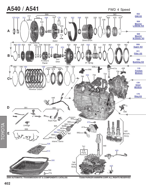
402A070034311530510520179209211022046500555229337336965975879565ForwardPlanetSun GearV.B.Parts741765992446995777778#1 Sprag036779940030Bushing Kit006Master W/Steels Kit 004Master L/Steels Kit002OHK Kit4032008 AUTOMATIC TRANSMISSION KIT & COMPONENTS CATALOG©2008 PARKER HANNIFIN CORP . ALL RIGHTS RESERVEDCD964974122564332333972124100144873888665654888584251246594604889894795207263268710268898590184580216661650694867120100039O.Dr. Cover7967122812806996966818950757350752********PinionFE077725290289720716847292076Differential Diff.Parts717G730715O.Dr. Direct Drum9352692693752917862886982008 AUTOMATIC TRANSMISSION KIT & COMPONENTS CATALOG©2008 PARKER HANNIFIN CORP. ALL RIGHTS RESERVED *Prefix Letter ‘T’ denotes Toledo-Trans Kit (TTK) Brand Transmission Kits*Prefix Letter ‘B’ denotes Bryco Brand Transmission Kits002.............T87002A........Overhaul Kit, A540E 1988-93.....................................................................................................1..........002.............B87002A.......Overhaul Kit, A540E 1988-93.....................................................................................................1..........002.............TF87002A......Overhaul Kit, A540E 1988-93 (Fiber Pan Gasket).....................................................................1..........002.............T87002AB.....Overhaul Kit, A540H (Camry AWD & RAV-4 4x4) 1989-Up......................................................1..........002.............B87002AB.....Overhaul Kit, A540H (Camry AWD & RAV-4 4x4) 1989-Up......................................................1..........002.............T87002B........Overhaul Kit, A541E 1994-Up....................................................................................................1..........002.............TF87002B......Overhaul Kit, A541E 1994-Up (Fiber Pan Gasket).....................................................................1..........002.............B87000B........Overhaul Kit, A541E 1994-Up....................................................................................................1..........004.............B87004A.......Master L/Steels Kit, A540E 1988-5/1991...................................................................................1..........004.............B87004A.......Master L/Steels Kit, A540E 6/1991-1993...................................................................................1..........004.............B87004B........Master L/Steels Kit, A541E 1994-Up..........................................................................................1..........006.............B87006AA.....Master W/Steels Kit, A540E 1988-5/1991..................................................................................1..........006.............B87006AA.....Master W/Steels Kit, A540E 6/1991-1993..................................................................................1..........008.............B87008A.......Super Kit, A540E 1988-91..........................................................................................................1..........E300...........24009T..........Gasket, A540 Oil Pan..................................................................................................................1..........35168-32020 E300...........24018............Gasket, A540 Oil Pan ( Fiber).....................................................................................................1..........(35168-32020) E300...........24009AT........Gasket, A541E Oil Pan 1994-Up.................................................................................................1..........35168-33010 E300...........24018A..........Gasket, A541E Oil Pan 1994-Up (Fiber).....................................................................................1..........(35168-33010) C302...........24097482......Gasket, A540 Top Cover............................................................................................................1..........35153-33010 G304..........24097481......Gasket, A540E/A540H Overdrive Cover (Rear Cover) 1988-Up..............................................1..........34112-32040 A311...........1994536........O-Ring, A540 Pump 1988-Up.....................................................................................................1..........90301-99024 E326...........24006............Gasket, A540 Filter 1988-Up......................................................................................................1..........35339-32020 E362...........1994137........O-Ring, A540 Servo Cover 1988-93..........................................................................................2..........90301-52003 E362...........1994132........O-Ring, A540 Servo Cover 1994-Up.........................................................................................2..........90301-43005 ...................1994584........O-Ring, A540 Filler Tube 1988-Up.............................................................................................1..........90301-09173 ...................1995509........O-Ring, A540 Speed meter Shaft 1988-Up................................................................................1..........96711-24030175.............6142..............Ring Kit, A540 (2 Metal, 8 PTFE).................................................................................................1..........175.............6142OS.........Ring Kit, A540 (2 Metal, 8 PTFE).................................................................................................1..........A177..........30528............Ring, A540 Forward Clutch (PTFE)............................................................................................3..........35712-32010 A179..........TAW-1344.....Ring, A540 Direct Clutch (Metal)................................................................................................2..........35617-16010 E184...........30524............Ring, A540 Intermediate Shaft (PTFE)........................................................................................1..........35748-32010 G185..........30526............Ring, A540 Overdrive Direct Clutch (PTFE)...............................................................................2..........35617-32011 E195...........30537............Ring, A540 2nd Coast Servo (PTFE) 1988-Up...........................................................................1..........35865-32020 E195...........30527............Ring, A541 2nd Coast Servo (PTFE) 1994-Up...........................................................................1..........35865-33010404B100...........24020............Friction, A540 Reverse Clutch (.059") 33 Teeth (5.60"OD)......................................................6-7........35677-32060B100...........24020A..........Friction, A541A Reverse Clutch (.063") 36 Teeth (5.59 OD) 1994-Up.....................................6-7........35677-33040B100...........240022R........Friction, A540 2nd Brake Clutch (.075") 33 Teeth (5.60"OD) 1992-Up.....................................3..........A106..........24026A..........Friction, A540 Forward Clutch (.060") 40 Teeth (5.00"OD) 1992-Up.......................................5..........35633-33010B106...........24028............Friction, A540 Direct Clutch (.083") 40 Teeth (5.20"OD) 1992-Up............................................3..........35633-20010 119.............24080R..........Friction Module A540E 188-91...................................................................................................1.......... 119.............24080............Friction Module A540E 188-91...................................................................................................1.......... 119.............24080AR.......Friction Module A540E 1991-93.................................................................................................1.......... 119.............24080AT........Friction Module A540E 1991-93.................................................................................................1.......... 119.............24080CR........Friction Module, A540H AWD 1989-Up......................................................................................1.......... 119.............24080C..........Friction Module, A540H AWD 1989-Up......................................................................................1.......... 119.............24080BR........Friction Module, A541E 1994-Up................................................................................................1..........A122..........25821C..........Steel, A540 Forward Clutch (.071") 4.10"ID (8 Teeth) 1988-91................................................4..........35634-12040A122..........25821A..........Steel, A540 Forward Clutch (.063") 8 Teeth (4.10"ID) 1992-Up...............................................4..........35634-33010A122..........25821B..........Steel, A540 Forward Clutch (.055") 8 Teeth (4.10"ID) 1992-Up..............................................1-5........35634-33020A122..........24027............Steel, A540 Direct Clutch (.071") 6 Notched Teeth (4.10"ID) 1988-91......................................1..........35634-32020A122..........24027A..........Steel, A540 Direct Clutch (.055") 6 Teeth (4.10"ID) 1992-Up....................................................1..........35634-33030A122..........24027B..........Steel, A540 Direct Clutch (.079") 6 Teeth (3 Teeth Are Notched) 4.10"ID................................2-3........35647-33020F122...........24021............Steel, A540 Overdrive Direct Clutch (.118") 4.10"ID (24 Teeth) 1989-93.................................2..........34615-20010F122...........24021A..........Steel, A541E Overdrive Direct Clutch (.071") 24 Teeth (4.10"ID) 1994-Up...............................2..........34615-33030 ...................25829............Steel, A540 Differential Clutch (.063") 3.60"ID (30 Teeth) 1988-Up..........................................11.........41474-32011B124...........24029............Steel, A540 2nd Brake Clutch (.071") 12 Teeth (4.60"ID) 1988-Up...........................................3..........35648-32030B124...........24025A..........Steel, A541E 2nd Brake Clutch (.071") 10 Teeth (4.86"ID) 1994-Up (Wide Splined)................4..........35648-33010C130...........24029A..........Steel, A541E Reverse Clutch (.063") 10 Teeth (4.86"ID) 1994-Up (Narrow Spline).................6..........35648-33020 139.............24081............Steel Module, A540E 1988-91....................................................................................................1.......... 139.............24081A..........Steel Module, A540E 1991-93....................................................................................................1.......... 139.............24081C..........Steel Module, A540H AWD 1989-Up..........................................................................................1.......... 139.............24081B..........Steel Module, A541E 1994-Up....................................................................................................1..........E010...........25842B..........Filter, A540E/A540H 1988-Up.....................................................................................................1..........E010...........24040B..........Filter, A541E 1994-96.................................................................................................................1..........011.............24041............Filter Kit, A540E/A540H 1988-94................................................................................................1.......... 011.............24041A..........Filter Kit, A540E/A540H 1988-94 (Fiber Pan Gasket)................................................................1.......... 011.............24043............Filter Kit, A541E 1994-Up...........................................................................................................1..........G039..........24033............Bushing, A540 Overdrive Direct Drum (Rear)...........................................................................1..........A046..........24032............Bushing, A540 Direct Drum........................................................................................................1..........B050...........24035............Bushing, A540 Input Hub............................................................................................................1..........B052...........24031............Bushing, A540 Sun Gear...........................................................................................................2..........2008 AUTOMATIC TRANSMISSION KIT & COMPONENTS CATALOG©2008 PARKER HANNIFIN CORP. ALL RIGHTS RESERVED4054062008 AUTOMATIC TRANSMISSION KIT & COMPONENTS CATALOG ©2008 PARKER HANNIFIN CORP. ALL RIGHTS RESERVEDE216...........24073............Washer, A540 Overdrive Planet To Overdrive Drum.................................................................1..........34737-3310...................24074............Washer, A540E Planetary Carrier Sun Gear 1988-93...............................................................1..........35739-32020...................24074A..........Washer, A541E Planet Carrier #3 1994-Up................................................................................1..........35739-33010...................24072............Washer, A540E Planetary Carrier Front 1988-93......................................................................1..........35738-32020...................24072A..........Washer, A541E Planetary# 2 1994-Up ......................................................................................1..........35738-33020...................24071............Washer,A540E Planetary Carrier Rear 1988-93.......................................................................1..........35738-32030...................24071A..........Washer, A541E Planetary# 3 1994-Up ......................................................................................1..........35738-33010E425...........S-151.............Solenoid, A540 Lock-Up 1988-..................................................................................................1..........85420-32110E425...........89758............Solenoid, A540E, A540H Lock Up 1989-Up ...............................................................................1..........85420-32110E425...........S-118.............Solenoid, A541E Lock-Up 1994-04 OEM....................................................................................1..........35240-33010E420...........S-152.............Solenoid, A540E Shift 1, 2 1988-...............................................................................................1..........85420-32091E420...........89757............Solenoid, A540E, A540H Shift 1988-93.....................................................................................1..........85420-32091E420...........S-110.............Solenoid, A541E Shift 1, 2 1994- OEM.......................................................................................1..........85420-33010E420...........89757A..........Solenoid, A541E Shift 1994-Up ..................................................................................................1..........85420-33010B642...........24085............Sprag Assembly, A540 (4 1/2"OD).............................................................................................1..........35790-320312008 AUTOMATIC TRANSMISSION KIT & COMPONENTS CATALOG©2008 PARKER HANNIFIN CORP. ALL RIGHTS RESERVED407。
W3EG6464S-JD3中文资料

White Electronic Designs W3EG6464S-JD3-D3PRELIMINARY*FEATURESDouble-data-rate architectureDDR200 and DDR266• JEDEC design specifi cationBi-directional data strobes (DQS)Differential clock inputs (CK & CK#)Programmable Read Latency 2,2.5 (clock)Programmable Burst Length (2,4,8)Programmable Burst type (sequential & interleave) Edge aligned data output, center aligned data input. Auto and self refreshSerial presence detectPower supply: V CC: 2.5V ± 0.20VJEDEC standard 184 pin DIMM package• Package height option:JD3: 30.48mm (1.20")NOTE: C onsult factory for availability of:• Lead-Free Products• Vendor source control options• Industrial temperature options DESCRIPTIONThe W3E G6464S is a 64Mx64 Double Data Rate SDRAM memory module based on 512Mb DDR SDRAM components. The module consists of eight 64Mx8 DDR SDRAMs in 66 pin TSOP packages mounted on a 184 pin FR4 substrate.Synchronous design allows precise cycle control with the use of system clock. Data I/O transactions are possible on both edges and Burst Lengths allow the same device to be useful for a variety of high bandwidth, high performance memory system applications.* T his product is under development, is not qualifi ed or characterized and is subject to change without notice.512MB – 64Mx64 DDR SDRAM UNBUFFEREDOPERATING FREQUENCIESDDR266 @CL=2DDR266 @CL=2.5DDR266 @CL=2DDR200 @CL=2 Clock Speed133MHz133MHz133MHz100MHzCL-t RCD-t RP2-2-2 2.5-3-32-3-32-2-2White Electronic DesignsW3EG6464S-JD3-D3PRELIMINARYPIN SYMBOL PIN SYMBOL PIN SYMBOL PIN SYMBOL 1V REF 47DQS893V SS 139V SS 2DQ048A094DQ4140DQS173V SS 49CB295DQ5141A104DQ150V SS 96V CCQ 142CB65DQS051CB397DQS9143V CCQ 6DQ252BA198DQ6144CB77V CC 53DQ3299DQ7145V SS 8DQ354V CCQ 100V SS 146DQ369NC 55DQ33101NC 147DQ3710RESET#56DQS4102NC 148V CC 11V SS 57DQ34103NC 149DQS1312DQ858V SS 104V CCQ 150DQ3813DQ959BA0105DQ12151DQ3914DQS160DQ35106DQ13152V SS 15V CCQ 61DQ40107DQS10153DQ4416NC 62V CCQ 108V CC 154RAS#17NC 63WE#109DQ14155DQ4518V SS 64DQ41110DQ15156V CCQ 19DQ1065CAS#111NC 157CS0#20DQ1166V SS 112V CCQ 158NC 21CKE067DQS5113NC 159DQS1422V CCQ 68DQ42114DQ20160V SS 23DQ1669DQ43115A12161DQ4624DQ1770V CC 116V SS 162DQ4725DQS271NC 117DQ21163NC 26V SS 72DQ48118A11164V CCQ 27A973DQ49119DQS11165DQ5228DQ1874V SS 120V CC 166DQ5329A775NC 121DQ22167NC 30V CCQ 76NC 122A8168V CC 31DQ1977V CCQ 123DQ23169DQS1532A578DQS6124V SS 170DQ5433DQ2479DQ50125A6171DQ5534V SS 80DQ51126DQ28172V CCQ 35DQ2581V SS 127DQ29173NC 36DQS382V CCID 128V CCQ 174DQ6037A483DQ56129DQS12175DQ6138V CC 84DQ57130A3176V SS 39DQ2685V CC 131DQ30177DQS1640DQ2786DQS7132V SS 178DQ6241A287DQ58133DQ31179DQ6342V SS 88DQ59134CB4180V CCQ 43A189V SS 135CB5181SA044CB090NC 136V CCQ 182SA145CB191SDA 137CK0183SA246V CC92SCL138CK0#184V CCSPDPIN CONFIGURATIONA0-A12Address input (Multiplexed)BA0-BA1Bank Select Address DQ0-DQ63Data Input/Output CB0-CB7Check bitsDQS0-DQS17Data Strobe Input/Output CK0Clock Input CK0#Clock InputCKE0Clock Enable input CS0#Chip Select Input RAS#Row Address Strobe CAS#Column Address Strobe WE#Write Enable V CC Power SupplyV CCQ Power Supply for DQS V SS GroundV REF Power Supply for Reference V CCSPD Serial EEPROM Power Supply SDA Serial data I/O SCL Serial clockSA0-SA2Address in EEPROM V CCID V CC Indentifi cation Flag NCNo Connect RESET#Reset EnablePIN NAMESWhite Electronic Designs W3EG6464S-JD3-D3PRELIMINARY FUNCTIONAL BLOCK DIAGRAMWhite Electronic Designs W3EG6464S-JD3-D3PRELIMINARYABSOLUTE MAXIMUM RATINGSParameter Symbol Value Units Voltage on any pin relative to V SS V IN, V OUT-0.5 to 3.6VVoltage on V CC supply relative to V SS V CC, V CCQ-1.0 to 3.6VStorage Temperature T STG-55 to +150°CPower Dissipation P D8WShort Circuit Current I OS50mANote: Permanent device damage may occur if ‘ABSOLUTE MAXIMUM RATINGS’ are exceeded.Functional operation should be restricted to recommended operating condition.Exposure to higher than recommended voltage for extended periods of time could affect device reliabilityDC CHARACTERISTICS0°C ≤ T A≤ 70°C, V CC = 2.5V ± 0.2VParameter Symbol Min Max Unit Supply Voltage V CC 2.3 2.7V Supply Voltage V CCQ 2.3 2.7V Reference Voltage V REF 1.15 1.35V Termination Voltage V TT 1.15 1.35VInput High Voltage V IH V REF + 0.15V CCQ + 0.3VInput Low Voltage V IL-0.3V REF -0.15V Output High Voltage V OH V TT + 0.76—V Output Low Voltage V OL—V TT-0.76VCAPACITANCET A = 25°C. f = 1MHz, V CC = 2.5V ± 0.2VParameter Symbol Max UnitInput Capacitance (A0-A12)C IN129pFInput Capacitance (RAS#,CAS#,WE#)C IN229pFInput Capacitance (CKE0)C IN329pFInput Capacitance (CK0#,CK0)C IN426pFInput Capacitance (CS0#)C IN529pFInput Capacitance (DQM0-DQM8)C IN68pFInput Capacitance (BA0-BA1)C IN729pFData input/output capacitance (DQ0-DQ63)(DQS)C OUT8pFData input/output capacitance (CB0-CB7)C OUT8pFWhite Electronic Designs W3EG6464S-JD3-D3PRELIMINARYI DD SPECIFICATIONS AND TEST CONDITIONS0°C ≤ T A≤ 70°C, V CCQ = 2.5V ± 0.2V, V CC = 2.5V ± 0.2VIncludes DDR SDRAM component onlyParameter Symbol Conditions DDR266@CL=2MaxDDR266@CL=2.5MaxDDR266 &200@CL=2Max UnitsOperating Current I DD0One device bank; Active - Precharge; t RC=t RC(MIN); t CK=t CK (MIN); DQ,DM and DQS inputschanging once per clock cycle; Address and controlinputs changing once every two cycles.132013201320mAOperating Current I DD1One device bank; Active-Read-Precharge Burst= 2; t RC=t RC (MIN); t CK=t CK (MIN); l OUT = 0mA;Address and control inputs changing once perclock cycle.152015201520mAPrecharge Power-Down Standby Current I DD2P All device banks idle; Power-down mode; t CK=t CK(MIN); CKE=(low)484848rnAIdle Standby Current I DD2F CS# = High; All device banks idle; t CK=t CK (MIN);CKE = high; Address and other control inputschanging once per clock cycle. V IN = V REF for DQ,DQS and DM.400400400mAActive Power-Down Standby Current I DD3P One device bank active; Power-Down mode; t CK(MIN); CKE=(low)400400400mAActive Standby Current I DD3N CS# = High; CKE = High; One device bank; Active-Precharge; t RC=t RAS (MAX); t CK=t CK (MIN); DQ, DMand DQS inputs changing twice per clock cycle;Address and other control inputs changing onceper clock cycle.760760760mAOperating Current I DD4R Burst = 2; Reads; Continuous burst; One devicebank active; Address and control inputs changingonce per clock cycle; T CK= T CK (MIN); l OUT = 0mA.176017601760mAOperating Current I DD4W Burst = 2; Writes; Continuous burst; One devicebank active; Address and control inputs changingonce per clock cycle; t CK=t CK (MIN); DQ,DM andDQS inputs changing once per clock cycle.200020002000rnAAuto Refresh Current I DD5t RC = t RC (MIN)248024802480mA Self Refresh Current I DD6CKE ≤ 0.2V Standard404040 mALow Power252525Operating Current I DD7A Four bank interleaving Reads (BL=4) with autoprecharge with t RC=t RC (MIN); t CK=t CK (MIN);Address and control inputs change only duringActive Read or Write commands.384038403840mAWhite Electronic Designs W3EG6464S-JD3-D3PRELIMINARYI DD1 : OPERATING CURRENT : ONE BANK1. Typical Case : V CC=2.5V, T=25°C2. Worst Case : V CC=2.7V, T=10°C3. Only one bank is accessed with t RC (min), BurstMode, Address and Control inputs on NOP edgeare changing once per clock cycle. I OUT = 0mA4. Timing Patterns :• DDR200 (100 MHz, CL=2) : t CK=10ns, CL2, BL=4, t RCD=2*t CK, t RAS=5*t CKRead : A0 N R0 N N P0 N A0 N - repeat thesame timing with random address changing;50% of data changing at every burst• DDR266 (133MHz, CL=2.5) : t CK=7.5ns,CL=2.5, BL=4, t RCD=3*t CK, t RC=9*t CK, t RAS=5*t CKRead : A0 N N R0 N P0 N N N A0 N - repeatthe same timing with random addresschanging; 50% of data changing at every burst • DDR266 (133MHz, CL=2) : t CK=7.5ns, CL=2, BL=4, t RCD=3*t CK, t RC=9*t CK, t RAS=5*t CKRead : A0 N N R0 N P0 N N N A0 N - repeatthe same timing with random addresschanging; 50% of data changing at every burst I DD7A : OPERATING CURRENT : FOUR BANKS1. Typical Case : V CC=2.5V, T=25°C2. Worst Case : V CC=2.7V, T=10°C3. Four banks are being interleaved with t RC (min),Burst Mode, Address and Control inputs on NOPedge are not changing. Iout=0mA4. Timing Patterns :• DDR200 (100 MHz, CL=2) : t CK=10ns, CL2, BL=4, t RRD=2*t CK, t RCD=3*t CK, Read withAutoprechargeRead : A0 N A1 R0 A2 R1 A3 R2 A0 R3 A1 R0- repeat the same timing with random addresschanging; 100% of data changing at everyburst• DDR266 (133MHz, CL=2.5) : t CK=7.5ns,CL=2.5, BL=4, t RRD=3*t CK, t RCD=3*t CKRead with AutoprechargeRead : A0 N A1 R0 A2 R1 A3 R2 N R3 A0 NA1 R0 - repeat the same timing with randomaddress changing; 100% of data changing atevery burst• DDR266 (133MHz, CL=2) : t CK=7.5ns, CL2=2, BL=4, t RRD=2*t CK, t RCD=2*t CKRead : A0 N A1 R0 A2 R1 A3 R2 N R3 A0 NA1 R0 - repeat the same timing with randomaddress changing; 100% of data changing atevery burstDETAILED TEST CONDITIONS FOR DDR SDRAM I DD1 & I DD7ALegend:A = Activate, R = Read, W = Write, P = Precharge, N = NOPA (0-3) = Activate Bank 0-3R (0-3) = Read Bank 0-3White Electronic Designs W3EG6464S-JD3-D3PRELIMINARY DDR SDRAM COMPONENT ELECTRICAL CHARACTERISTICS ANDRECOMMENDED AC OPERATING CONDITIONS0°C ≤ T A ≤ +70°C; V CC = +2.5V ±0.2V, V CCQ = +2.5V ±0.2VAC Characteristics262/263/265202Parameter Symbol Min Max Min Max Units Notes Access window of DQs from CK, CK#t AC-0.75+0.75-0.75+0.75nsCK high-level width t CH0.450.550.450.55t CK16CK low-level width t CL0.450.550.450.55t CK16 Clock cycle time CL=2.5t CK (2.5)7.5137.513ns22CL=2t CK (2)7.5131013ns22 DQ and DM input hold time relative to DQS t DH0.50.5ns14,17 DQ and DM input setup time relative to DQS t DS0.50.5ns14,17 DQ and DM input pulse width (for each input)t DIPW 1.75 1.75ns17 Access window of DQS from CK, CK#t DQSCK-0.75+0.75-0.75+0.75nsDQS input high pulse width t DQSH0.350.35t CKDQS input low pulse width t DQSL0.350.35t CKt DQSQ0.50.5ns13,14 DQS-DQ skew, DQS to last DQ valid, per group,per accessWrite command to fi rst DQS latching transition t DQSS0.75 1.250.75 1.25t CKDQS falling edge to CK rising - setup time t DSS0.20.2t CKDQS falling edge from CK rising - hold time t DSH0.20.2t CKHalf clock period t HP t CH, t CL t CH, t CL ns18 Data-out high-impedance window from CK, CK#t HZ+0.75+0.75ns8,19 Data-out low-impedance window from CK, CK#t LZ-0.75-0.75ns8,20 Address and control input hold time (fast slew rate)t IHf0.900.90ns6 Address and control input set-up time (fast slew rate)t ISf0.900.90ns6 Address and control input hold time (slow slew rate)t IHs11ns6 Address and control input setup time (slow slew rate)t ISs11ns6 Address and control input pulse width (for each input)t IPW 2.2 2.2nsLOAD MODE REGISTER command cycle time t MRD1515nsDQ-DQS hold, DQS to fi rst DQ to go non-valid, per access t QH t HP-t QHS t HP-t QHS ns13,14 Data hold skew factor t QHS0.750.75nsACTIVE to PRECHARGE command t RAS40120,00045120,000ns15 ACTIVE to READ with Auto precharge command t RAP1520nsACTIVE to ACTIVE/AUTO REFRESH command period t RC6065nsAUTO REFRESH command period t RFC7575ns21White Electronic Designs W3EG6464S-JD3-D3PRELIMINARY DDR SDRAM COMPONENT ELECTRICAL CHARACTERISTICS ANDRECOMMENDED AC OPERATING CONDITIONS (continued)0°C ≤ T A ≤ +70°C; V CC = +2.5V ±0.2V, V CCQ = +2.5V ±0.2VAC Characteristics262/263/265202Parameter Symbol Min Max Min Max Units Notes ACTIVE to READ or WRITE delay t RCD1520ns PRECHARGE command period t RP1520nsDQS read preamble t RPRE0.9 1.10.9 1.1t CK19 DQS read postamble t RPST0.40.60.40.6t CKACTIVE bank a to ACTIVE bank b command t RRD1515nsDQS write preamble t WPRE0.250.25t CKDQS write preamble setup time t WPRES00ns10,11 DQS write postamble t WPST0.40.60.40.6t CK9 Write recovery time t WR1515nsInternal WRITE to READ command delay t WTR11t CKData valid output window NA t QH-t DQSQ t QH-t DQSQ ns13 REFRESH to REFRESH command interval t REFC70.370.3μs12 Average periodic refresh interval t REFI7.87.8μs12 Terminating voltage delay to V CC t VTD00nsExit SELF REFRESH to non-READ command t XSNR7575nsExit SELF REFRESH to READ command t XSRD200200t CKWhite Electronic DesignsW3EG6464S-JD3-D3PRELIMINARY12. The refresh period is 64ms. This equates to an average refreshrate of 7.8125µs. However, an AUTO REFRESH command must be asserted at least once every 70.3µs; burst refreshing or posting by the DRAM controller greater than eight refresh cycles is not allowed.13. The valid data window is derived by achieving other specifi cations- t HP (t CK/2), t DQSQ , and t QH (t QH = t HP - t QHS ). The data valid window derates directly proportional with the clock duty cycle and a practical data valid window can be derived. The clock is allowed a maximum duty cycled variation of 45/55. Functionality is uncertain when operating beyond a 45/55 ratio. The data valid window derating curves are provided below for duty cycles ranging between 50/50 and 45/55.14. Referenced to each output group: x8 = DQS with DQ0-DQ7.15. READs and WRITEs with auto precharge are not allowed to beissued until t RAS (MIN) can be satisfi ed prior to the internal precharge command being issued.16. JEDEC specifi es CK and CK# input slew rate must be > 1V/ns(2V/ns differentially).17. DQ and DM input slew rates must not deviate from DQS by morethan 10%. If the DQ/DM/DQS slew rate is less than 0.5V/ns, timing must be derated: 50ps must be added to t DS and t DH for each 100mV/ns reduction in slew rate. If slew rates exceed 4V/ns, functionality is uncertain.18. t HP min is the lesser of t CL min and t CH min actually applied to thedevice CK and CK# inputs, collectively during bank active.19. This maximum value is derived from the referenced test load. Inpractice, the values obtained in a typical terminated design may refl ect up to 310ps less for t HZ (MAX) and last DVW. t HZ (MAX) will prevail over the t DQSCK (MAX) + t RPST (MAX) condition. t LZ (MIN) will prevail over t DQSCK (MIN) + PRE (MAX) condition.20. For slew rates greater than 1V/ns the (LZ) transition will start about310ps earlier.21. CKE must be active (High) during the entire time a refreshcommand is executed. That is, from the time the AUTO REFRESH command is registered, CKE must be active at each rising clock edge, until t REF later.22. Whenever the operating frequency is altered, not including jitter, theDLL is required to be reset. This is followed by 200 clock cycles (before READ commands).Notes1. All voltages referenced to V SS2. Tests for AC timing, I DD , and electrical AC and DC characteristicsmay be conducted at normal reference / supply voltage levels, but the related specifi cations and device operations are guaranteed for the full voltage range specifi ed.3. Outputs are measured with equivalent load:4. AC timing and I DD tests may use a V IL -to-V IH swing of up to 1.5Vin the test environment, but input timing is still referenced to V REF (or to the crossing point for CK/CK#), and parameter specifi cations are guaranteed for the specifi ed AC input levels under normal use conditions. The minimum slew rate for the input signals used to test the device is 1V/ns in the range between V IL (AC) and V IH (AC).5. The AC and DC input level specifi cations are defi ned in the SSTL_2standard (i.e., the receiver will effectively switch as a result of the signal crossing the AC input level, and will remain in that state as long as the signal does not ring back above [below] the DC input LOW [high] level).6. Command/Address input slew rate = 0.5V/ns. For 262 with slewrates 1V/ns and faster, t IS and t IH are reduced to 900ps. If the slew rate is less than 0.5V/ns, timing must be derated: t IS has an additional 50ps per each 100mV/ns reduction in slew rate from the 500mV/ns. t IH has 0ps added, that is, it remains constant. If the slew rate exceeds 4.5V/ns, functionality is uncertain.7. Inputs are not recognized as valid until V REF stabilizes. Exception:during the period before V REF stabilizes, CKE ≤ 0.3 x V CCQ is recognized as LOW.8. t HZ and t LZ transitions occur in the same access time windows asvalid data transitions. These parameters are not referenced to a specifi c voltage level, but specify when the device output is no longer driving (HZ) and begins driving (LZ).9. The maximum limit for this parameter is not a device limit. Thedevice will operate with a greater value for this parameter, but system performance (bus turnaround) will degrade accordingly.10. This is not a device limit. The device will operate with a negativevalue, but system performance could be degraded due to bus turnaround.11. It is recommended that DQS be valid (HIGH or LOW) on or before theWRITE command. The case shown (DQS going from High-Z to logic LOW) applies when no WRITEs were previously in progress on the bus. If a previous WRITE was in progress, DQS could be high during this time, depending on t DQSS .Output (V OUT )White Electronic Designs W3EG6464S-JD3-D3PRELIMINARYORDERING INFORMATION FOR JD3Part Number Speed CAS Latency t RCD t RP Height*W3EG6464S262JD3133MHz/266Mb/s22230.48 (1.20")W3EG6464S263JD3133MHz/266Mb/s23330.48 (1.20")W3EG6464S265JD3133MHz/266Mb/s 2.53330.48 (1.20")W3EG6464S202JD3100MHz/200Mb/s22230.48 (1.20") NOTES:• Consult Factory for availability of Lead-Free products. (F = Lead-Free, G = RoHS Compliant)• P roduct specifi c part numbers are available for source control if needed, please consult factory for the correct part number if a specifi c component vendor is preferred.• Consult factory for availability of industrial temperature (-40°C to 85°C) optionPACKAGE DIMENSIONS FOR JD3* ALL DIMENSIONS ARE IN MILLIMETERS AND (INCHES)White Electronic Designs W3EG6464S-JD3-D3PRELIMINARYORDERING INFORMATION FOR D3Part Number Speed CAS Latency t RCD t RP Height*W3EG6464S262D3133MHz/266Mb/s22230.48 (1.20")W3EG6464S263D3133MHz/266Mb/s23330.48 (1.20")W3EG6464S265D3133MHz/266Mb/s 2.53330.48 (1.20")W3EG6464S202D3100MHz/200Mb/s22230.48 (1.20") NOTES:• Consult Factory for availability of Lead-Free products. (F = Lead-Free, G = RoHS Compliant)• P roduct specifi c part numbers are available for source control if needed, please consult factory for the correct part number if a specifi c component vendor is preferred.• Consult factory for availability of industrial temperature (-40°C to 85°C) optionPACKAGE DIMENSIONS FOR D3* ALL DIMENSIONS ARE IN MILLIMETERS AND (INCHES)Document Title512MB- 64Mx64, DDR SDRAM UNBUFFEREDRevision HistoryRev #History Release Date Status Rev 0Created Datasheet9-23-02Advanced Rev 1 1.1 Removed "ED" from part marking1.2 Updated CAP and I DD specs4-8-04PreliminaryRev 2 2.1 Added lead-free and RoHS notes2.2 Added vendor source control notes2.3 Added industrial temp notes12-04PreliminaryRev 3 3.1 Added JEDEC Standard PCB3.2 D3 Not Recommended For new Designs 5-05PreliminaryWhite Electronic Designs W3EG6464S-JD3-D3PRELIMINARY。
ES6461 PDF

Details on licensing or membership can be obtained at
MPEG-2/MPEG-4:
Details on licensing or membership can be obtained at
x
x
x
√
X
x
√
√
x
√
√
√
K The DMPX has a versatile card reader interface for direct connection to CF/MicroDrive, SD, MMC,
MS/MS Pro, xD, SM, and IDE hard drives. In addition, HS USB 2.0 host/device interfaces are included
the emerging HDD Media Player products.
KEY FEATURES i d e n Feature
Audio/Video
f • 4ch Video DAC n • 8/12-bit Digital Video Out
• Stereo Audio DAC
o System & Peripheral • 32kB RISC cache C • TCON
K USB Device
USB SATA/PATA
Subsystem
DMPX
EESS66443601 17D6M-LPQ3 FP
Host I/F
C Memory Cards
CVBS, S-Video, Component 2CH Audio Out SPDIF Digital Out
SN54LVC646A资料

元器件交易网IMPORTANT NOTICETexas Instruments and its subsidiaries (TI) reserve the right to make changes to their products or to discontinueany product or service without notice, and advise customers to obtain the latest version of relevant informationto verify, before placing orders, that information being relied on is current and complete. All products are soldsubject to the terms and conditions of sale supplied at the time of order acknowledgement, including thosepertaining to warranty, patent infringement, and limitation of liability.TI warrants performance of its semiconductor products to the specifications applicable at the time of sale inaccordance with TI’s standard warranty. Testing and other quality control techniques are utilized to the extentTI deems necessary to support this warranty. Specific testing of all parameters of each device is not necessarilyperformed, except those mandated by government requirements.CERTAIN APPLICATIONS USING SEMICONDUCTOR PRODUCTS MAY INVOLVE POTENTIAL RISKS OFDEATH, PERSONAL INJURY, OR SEVERE PROPERTY OR ENVIRONMENTAL DAMAGE (“CRITICALAPPLICATIONS”). TI SEMICONDUCTOR PRODUCTS ARE NOT DESIGNED, AUTHORIZED, ORWARRANTED TO BE SUITABLE FOR USE IN LIFE-SUPPORT DEVICES OR SYSTEMS OR OTHERCRITICAL APPLICATIONS. INCLUSION OF TI PRODUCTS IN SUCH APPLICATIONS IS UNDERSTOOD TOBE FULLY AT THE CUSTOMER’S RISK.In order to minimize risks associated with the customer’s applications, adequate design and operatingsafeguards must be provided by the customer to minimize inherent or procedural hazards.TI assumes no liability for applications assistance or customer product design. TI does not warrant or representthat any license, either express or implied, is granted under any patent right, copyright, mask work right, or otherintellectual property right of TI covering or relating to any combination, machine, or process in which suchsemiconductor products or services might be or are used. TI’s publication of information regarding any thirdparty’s products or services does not constitute TI’s approval, warranty or endorsement thereof.Copyright © 1998, Texas Instruments Incorporated。
- 1、下载文档前请自行甄别文档内容的完整性,平台不提供额外的编辑、内容补充、找答案等附加服务。
- 2、"仅部分预览"的文档,不可在线预览部分如存在完整性等问题,可反馈申请退款(可完整预览的文档不适用该条件!)。
- 3、如文档侵犯您的权益,请联系客服反馈,我们会尽快为您处理(人工客服工作时间:9:00-18:30)。
-55-+85 -55-+125
Temperature: 260'C or less
RTC·64611 (Lead part)
Soldering conditions
Tsol.
Time: 10 sec.
RTC·646 I3
0.3V for SOns pulse width
Under 260'C within 1Osee x 2 or under 230'C within 3 min.
11/01 '99 MON 10:47 FAX 49 89 14005 110
EPSON EUROPE ELECTRONICS
I4i 007
4
RTC-64611/64613
Fig.1 Low Voltage Data holding Wave Form
Voo
Fig.2 Oscillation start time of Timing Wave Form
V V
"A "A
-
-
"A V V
pF pF
V"
VOL
2.4
0.4 12.5 12.5 2.0
=2.1mA
Input capacity
Output capacity
C"
CONT
100
V" OV Ta =25·C f =1.0MHz
No load. min. cycle
-
-
-
Current consumption (at bus access)
Symbol
Measuring conditions
VoD =5V±10%
Vno =2V
MIN
MAX
MIN
Vo[)-O.2
MAX
Unit
V" V"
I"
--
ITSL
ILQH
----1 = -lmA 011
10L
2.2 -0.3
-
v"
0.8 ± 2 ±1O ±1O
v"
0.2 ± 2 ±10 ±1O
-
-0.3
*Alloweble value for GND. * *
2 Operating range
Item
Supply voltage
Symbol
Condition
Range
4.5-5.5 -20-+ 75
Unit
V DD
Ta=-20-+75'C VDD -4.5-5.5V
V 'C
Operating temperature
@ I/O timing reference level: 1.5V
@ Output load: 1 TIL gate+C, (100pF) (including the scope and jig capacity)
(2) Read cycle
Read cycle
Read cycle time
Symbol
TOPR
3. Frequency characteristics
Item
Condition
,
.."Range
+15/- 5 (5±10) Ta=25'C
Voll =5V
Unit
RTC·64611A
Frequency tolerance
RTC·64611 B RTC·64613A RTC-64613
+55/ -45 (5±50) +25/-15 (5±20) +55/ -45 (5±50) +10/-120 +10/ -220 ± 5 ± 5
I4i 009
RTC-64611/64613
cr>
Read cycle·3 timing wave form
* 1, and * 4
,~
!
-...,
lACS
tCHZ
telz
,
XXX
f\.
Data Valid
f--
'5
* 1. In read cycle, keep WE "High". * 2. The device is always selected in CS=V * 3. The address must be defined simultaneously with or before activation of es. * 4. OE=V * 5. During read, read data varies as the contents of the register change.
I" I"
tAcs
MIN
MAX
Unit
ns ns ns ns ns ns ns ns ns
85
85 45 45 -
Address access time
Chip select access time Output enable access time Output hold time Chip select/output set time
CS control
Fig.3 IRQ Control Timing
Fig.4 H·START/STOP Control Timing
H·STAAT (STOP
Internal counter
Stop
t
HSO
Fig.5 RESET Control Timing
.~
t HSO
Fig.6 AOJ Control Timing
-----:'""',...,,1
Data holding mode
t,
2.2V VOA;<;:2.0V Voo
4.5V
CS_o~
Note:
~S=~D~-~.:.V
_
Osciliation
+-__
~'-"LI.!-"I...l.L.l.L.l.!...l.L..
_
the address buffer, data buffer, WE buffer, and DE buffer. When the battery backup mode 1s controlled, the VIN level (address. data, and WE and DE) may be at a high impedance.
11/01 '99 MON 10: 45 FAX 49 89 14005 110
EPSON EUROPE ELECTRONICS
I4i 001
REAL TIME CLOCK MODULE
RTC-64611/64613 . ~ , APPLICATION MANUAL
EPSON
•
11/01
'99
MON 10:46 FAX 49 89 14005 110
2.0
-
4.5 2.0
V I'A ns ns
Data holding current consumption
vD ,=2.0, CSil; 1.8V H.START/STOPil; i.8V
IRQ with 1 MHz kept open.
0 85 (t,d
Chip select data hold time Operation recovery time
Ta=25"C, V =4.S-5.5V DD
PPM/V
4. Data holding characteristics at low supply voltages
Item
Data holding voltage
Symbol
Condition
MIN
TYP
MAX
Un"
V, D
IDDDR
CS!itV DD -O.2V
I,
--
0.5-+7.0
V V mA mA 'C
-1 1
-0.5*
* . . . .V
5 50
DD
+O.3
Allowable output current
Total allowable output current
Storage
1 :l:1,
--VOD=OV
temperature
I I
RTC·64611 RTC·64613
TCDR
T,
See Fig. 1.
-
-
Unit sec
psec
Note: tRc· .. ·.. Read cycle time
5. Oscillation characteristics and control signal timing
Rem
Crystal oscillation start time IRQ release time H.START/STOP control delay time
-
mA
-4-
11/01 '99 MON 10:48 FAX 49 89 14005 110
EPSON EUROPE ELECTRONICS
I4i 008
EPSON
7. AC characteristics (Unless otherwise specified,) (I) AC characteristics measuring conditions (applicable to the read and write cycies) CD Input pulse level: O.B-2AV ® Input rise/fall time: 5 ns