六足机器人套件使用向导及简单排错
高负载六足机器人定位系统H-845说明书

High-Load Hexapodp o s i t i o n i n g1t o n w i t h M i c r o M e t e r p r e c i s i o nh-845Load capacity to 1000 kgVelocity to 50 mm/sRepeatability to ±0.5 µmTravel ranges to 340 mm / 60°S calable design: Dimensions,travel ranges and loadsReference-class 6-axis positioning systemParallel-kinematic design for six degrees of freedom making it significantly more compact and stiff than serial-kinematic systems, higher dynamic range, no moved cables: Higher reliability, reduced friction. Large clear aperture. Brushless DC motors with brakesRapid implementation of customer requestsThe high-load Hexapod has a modular structure and uses a set of different modules for motor/drive unit and joint. The platforms can be adapted to the customer‘s appli-cation. This allows for rapid implementation of special customer requirements Powerful digital controller, open software architecture6D vector motion controller for Hexapods, incl. two additional servo axes. Arbitrary, stable pivot point, soft- ware-selectable. Positions commanded in Cartesian coordinates. Macro command language. Open-source LabVIEW driver and libraries. Determination of the work-space. Virtual machine for Hexapod emulation. Optional: Software for avoiding collisions in restricted workspace Fields of applicationResearch and industry. For astronomy, aviation and aerospacePhysikInstrumente(PI)GmbH&Co.KG213.Subjecttochangewithoutnotice.Latestreleasesavailableatwww.pi.ws.13/4/3.Option EtherCAT® is a registered trademark and patented technology, licensed by Beckhoff Automation GmbH, Germany.SpecificationsActive axesX, Y, Z, θX , θY , θZ X, Y, Z, θX , θY , θZ X, Y, Z, θX , θY , θZ X, Y, Z, θX , θY , θZ X, Y, Z, θX , θY , θZ X, Y, Z, θX , θY , θZ Motion and positioning Travel range* X, Y ±110±170±110±170±110±170mm Travel range* Z ±50±105±50±105±50±105mm Travel range* θX , θY ±15±20±15±20±15±20°Travel range* θZ±30±30±30±30±30±30°Single- actuator design resolution0.040.040.080.080.10.1µm Min. incremental motion X, Y 1122 2.5 2.5µm typ.Min. incremental motion Z0.50.51111µm typ.Min. incremental motion θX , θY , θZ151530303030µrad typ.Backlash X, Y 5510101010µm typ.Backlash Z 112222µm typ.Backlash θX , θY 151530303030µrad typ.Backlash θZ 303060606060µrad typ.Repeatability X, Y ±2±2±4±4±5±5µm typ.Repeatability Z ±0.5±0.5±1±1±2±2µm typ.Repeatability θX , θY , θZ ±10±10±20±20±25±25µrad typ.Max. velocity X, Y, Z 202040405050mm/s Max. velocity θX , θY , θZ 5050100100120120mrad/ s Typ. Velocity X, Y, Z 101020202525mm/ s Typ. Velocity θX , θY , θZ 202040405050mrad/s Mechanical propertiesLoad (base plate horizontal / anyo rientation)1000 / 3001000 / 300500 / 150500 / 150400 / 120400 / 120kg max.Motor type Brushless DC motor Brushless DC motor Brushless DC motor Brushless DC motor Brushless DC motor BrushlessDC motorMiscellaneousOperating temperature range -10 to 50-10 to 50-10 to 50-10 to 50-10 to 50-10 to 50°CMaterial Aluminum Aluminum Aluminum Aluminum Aluminum Aluminum Mass 120150120150120150kg ±5 %Cable length 999999m±10 mmController Included in deliveryC-887C-887C-887C-887C-887C-887Technical data specified at 20 ±3 °C.Ask about custom designs!* The travel ranges of the individual coordinates (X, Y, Z, θX , θY , θZ ) are interdependent. The data for each axis in this table shows its maximum travel, where all other axes are at their zero positions. If the other linear or rotational coordinates are not zero, the available travel may be less.Order InformationH-845.D11High- Load Hexapod for 1000 kg Load, Travel Ranges ±110 mm (X, Y), ±50 mm (Z), Max. Velocity 20 mm/ s.Cable Set 9 m, with 6- D Hexapod Controller, Control of 2 Additional Servo- Motor Axes Included, TCP/ IP and RS-232 InterfaceH-845.D21High- Load Hexapod for 1000 kg Load, Travel Range ±190 mm (X, Y), ±105 mm (Z), Max. Velocity 20 mm/ s.Cable Set 9 m, with 6- D Hexapod Controller, Control of 2 Additional Servo- Motor Axes Included, TCP/ IP and RS-232 InterfaceH-845.D31High- Load Hexapod for 500 kg Load, Travel Ranges ±110 mm (X, Y), ±50 mm (Z), Max. Velocity 40 mm/ s.Cable Set 9 m, with 6- D Hexapod Controller, Control of 2 Additional Servo- Motor Axes Included, TCP/ IP and RS-232 InterfaceH-845.D41High- Load Hexapod for 500 kg Load, Travel Ranges ±170 mm (X, Y), ±105 mm (Z), Max. Velocity 40 mm/ s.Cable Set 9 m, with 6- D Hexapod Controller, Control of 2 Additional Servo- Motor Axes Included, TCP/ IP and RS-232 InterfaceH-845.D51High- Load Hexapod for 400 kg Load, Travel Range ±110 mm (X, Y), ±50 mm (Z), Max. Velocity 50 mm/ s.Cable Set 9 m, with 6- D Hexapod Controller, Control of 2 Additional Servo- Motor Axes Included, TCP/ IP and RS-232 InterfaceH-845.D61High- Load Hexapod for 1000 kg Load, Travel Ranges ±170 mm (X, Y), ±105 mm (Z), Max. Velocity 50 mm/ s.Cable Set 9 m, with 6- D Hexapod Controller, Control of 2 Additional Servo- Motor Axes Included, TCP/ IP and RS-232 Interface, 19'' ChassisAsk about custom designs!Controllers / Drivers / AmplifiersC-887Controller for Hexapod Positioning SystemsRelated ProductsH-8506- Axis HexapodH-850KMLD High- Load HexapodH-850KHLC Precision Hexapod for High LoadsM-850KHTH1000 kg High- Load HexapodM-850KHLH Vacuum- Compatible High- Load HexapodHP-550HexapodM-850KWAH Weather- Resistant Hexapod for AstronomyTechnologyHexapods – Parallel- Kinematics Positioning Systems | Hexapod platforms are used for precision positioning and alignment of loads in all six degrees of freedom, three linear axes, and three rotational axes. Learn more ...Modular, Scalable High-Load Hexapod Concept Quick & Economical for 6-Axis Positioning Tasks e lectronics for reference point switches, limit switches, position commutation for the brush-less DC motors. T heir standard-ized joints allow them to be com-bined with almost any type of geometry of the base and top plates.These modular Hexapod systems are suitable for loads of up to 400 kg in any orientation and up to 1,000 kg in Their positioning velocities reach up to 20 mm/s, and their bidirectional repeatability amounts to about 5 μm. The purpose-designed igital controller handles all coordinatea stable freely programmable pivot point and comes with a solid package of Complex positioning tasks are rarely alike and individual solutions are often required. T his is also true of the Hexapod parallel-kinematic systems employed to precisely position heavy loads in six degrees of freedom. A modular concept now ensures that individual require-ments can be implemented within a very short period of time and easily inte-grated into the application.Hexapods have six actuators, which simultaneously move a common p latform, enabling a combination of high precision, stiffness and dynamics not achieved with serial kinematic designs. PI has now developed a modular concept that allows application-specifi c adjust-ments within a short period of time.PI’s modular Hexapod struts are designed such that their length can be scaled e asily. They include the required The modular Hexapod con-cept allows easy vidual requirements. oftware tools and drivers. In additionpod Conceptmical for ng Taskselectronics forreference pointswitches, limitswitches,positions ensors and electronic commutation for the brus h-less DC motors. heir standa rd d -ized joints allow them to be e c om m -bined with almost any ty pe e o f geometry of the base and top p la te s.These modular Hexapod syst ems ar e suitable for loads of up to 400 kg in any orientation and up to 1,000 kg in h orizontal position. Their positioning velocities reach up to 20 mm/s, and their bidirectional repeatability amounts to about 5 μm. The purpose-designed d igital controller handles all coordinate transformations, features vector control,a stable freely programmable pivot point and comes with a solid package ofy n d to x pt e-ry e-ch n h ot s.pt t-ed d d The T mo o dul arHex apo d c on-cept allo ws eas y adaptation to indi-vidual requirements.s oftware tools and dr iv er s. I n ad diti on to the Hexapod, the controller can hand-le two more independent motor axes as well.Clock Synchronization for the Entire Automation Line:Hexapods Communicate via Fieldbus Interfaces The benefits of parallel-kinematic recision positioning systems can now also be used in automation technology. PI’s high performance Hexapods can eldbus inter-Fieldbus interfaces are currently vailable as plug-in modules for Profi - net, CANopen and SERCOS. Due to this direct connection, Hexapod systems can be integrated invirtually any automated production line; a clock synchronization with other auto-mated components can easily be achieved, for example, for automated supply systems, machining or other complex adjusting processes.Here, the PLC defi nes the target position and trajectories in Cartesian coordinates;in return, it gets the actual positions over the fi eldbus interface. All other calcula-tions are handled by the Hexapod controller, i.e. transforming the nominal positions from Cartesian coordinates into the drive commands for the indi-vidual drives. T he controller acts like an intelligent drive. The cycle times for determining new positions, evaluating signals and synchronizing are between 1 and 3 milliseconds.Clock synchronization for the entire automa-tion line: Hexapods communicate via fi eld-bus interfaces.Fieldbus Slave Cartesian Nominal PositionSPS/CNC(Fieldbus Master)Actual The Hexapod controller acts like an intelligent drive. Due to the exchangeability of the fi eld-bus interface, communication with numerous types of PLC or CNC controllers is possible.Clock Synchronization forHexapods Cvia FieldbusThe benefits of parallel-p recision positioning system also be used in automation t PI’s high performance Hexcommunicate directly via fi e faces with a PLC controller.Fieldbus interfaces area vailable as plug-in module bus, EtherCAT , Profi net, CASERCOS. Due to this direct c Hexapod systems can be in Fieldbus Sla InterfaceCartesianNominal (Fieldbus Cartesian Actual PositionThe Hexapod controller acts like bus interface, communication wVertical Integration and Production CapacitySwivel unit, capable of carrying loads to 7 t, for measurements in application situationThe product range from a two-ton Hexapod to a 10-gram nano-positioner requires that PI can both manufacture and qualify these systems.■ Production and mounting at clean room conditions ■ Large quantities■ Stable measuring conditions■ Traceable, calibrated measuring instruments■ M onitoring of piezo actuator technology from material compositionto final inspection■In-house production of position sensorsAutomated production of PICMA ®multilayer piezo actuators in large quantitiesTest laboratories for measuring accura-cies down to picometers set standardsController for Hexapod Positioning Systems 6-D V e c t o r M o t i o n c o n t r o l,c o M p r e h e n s i V e F u n c t i o n a l i t yc-887S ophisticated controllerusing vector algorithmsF reely programmable,virtual pivot pointD ata recorderM acro program functionalityS tand-alone operation possibleand control through TCP/IP andRS-232 interfacesE xtensive software supportDigital controller for 6-axis-parallel kinematicsIncluded in the delivery of all PI standard Hexapod systemsC-887.11, 19“ controller, comprises the control for twoadditional single axes with servo motors, the functionalitycan be enhanced with many additional optionsC-887.21 compact bench-top controller for a lowersystem priceExtensive software supportFunctionsReal-time system. Position control using Cartesiancoordinates, vectorized motion. Stable, virtual pivot pointcan be defined freely in the working space. Data recorderfor recording operating parameters such as motor control,velocity, position or position error. Macro commandlanguage. Stand-alone operation possible with Autostartmacro or connection of keyboard and monitor. Optional:Manual control unitCustom designsCustom designs are available for use at high altitudes,e.g. for astronomical telescope applications. Processingof absolute sensors. Control of motor brakes. Processing ofadditional (redundant) position sensors for increased safetyrequirements, e.g. in medical technology|©P h y s i k I n s t r u m e n t e ( P I ) G m b H & C o . K G 2 0 1 2 . S u b j e c t t o c h a n g e w i t h o u t n o t i c e . L a t e s t r e l e a s e s a v a i l a b l e a t w w w . p i . w s . 1 2 / 0 5 / 2 2 . 0SoftwarePIMikroMove user software. Common commandset for all PI positioning systems. Shared libraries for Windows and Linux. Complete set of LabVIEW VI’s. Graphical user interfaces, configuration software and graphically displayed scan routine.Optional: PIVeriMove software for checking a restricted operating spaceInterfacesTCP/IP Ethernet can also be used for remote control and service, RS-232. Monitor, mouse and keyboard interface. On request: RS-422 for up to 1.4 km cable lengthPossible enhancements for C-887.11A nalog interfaces/photometer cards for visible light (F-206.VVU) or the infrared light range (F-206.iiU)F-206.NCU fast piezo nano-alignment system for alignment with nanometer precision| M i c r o p o s i t i o n i n gH e x a K i-887.11Function 6-D controller for Hexapods, 19“,6-D controller for Hexapods,incl. control of two additional single axes, compact bench-top for a lower system pricecan be enhanced with many optionsDrive type Servo motors (Hexapod and additional axes) Servo motorsOptional: Piezo drives Motion and control Servo characteristics 32-bit PID filterTrajectory profile modes Trapezoid, linear interpolationProcessor CPU: 1.8 GHz, motion control chip with 2.5 kHz servo update rate Encoder input AB (quadrature) differential TTL signal, 5 MHz Stall detectionServo off, triggered by position error Reference point switch TTL signalElectrical propertiesMax. output power per channel 10-bit output for PWM drivers, 24 kHz Max. output voltage per channel TTL in PWM operation for SIGN and MAGNInterface and operation Communication interfaces TCP/IP , RS-232VGA (monitor), USB (keyboard, mouse, manual control unit)Hexapod connection MDR, 68-pin for data transmissionM12 4-pin. for power supplyConnection for additional single axes 15-pin sub-D –I/O ports Optional: Analog inputs (photometer cards) –Command set PI General Command Set (GCS)User software PIMikroMoveSoftware drivers LabVIEW driver, shared libraries for Windows and Linux Manual control Optional: C-887.MC control unit for Hexapods MiscellaneousOperating voltage100 to 240 VAC, 50 / 60 Hz Operating temperature range 5 to 40°C Mass 11 kg5 kgDimensions395 × 483 × 185 mm255 × 226 × 185 mm All PI Hexapod systems are delivered with an extensive software package. Included are simulation programs that calculate the working space of theHexapod and the individual loads on each actuator depending on the Hexapod orientation in spaceHighly advanced digital controllers are also available for Hexapods with piezo stepping drives which are suitable for operation in strong magnetic fields or UHV environmentsA p p e n d i xN a n o m e t r o l o g yN a n o p o s i t i o n i n g & P i e z o e l e c t r i c s L i n e a r A c t u a t o r s & M o t o r sHexapod-Specific SoftwareDue to their parallel kinematic structure, Hexapods necessitate a particularly complex control system. The position coordinates, for example, are given in virtu-al Cartesian axes which are then converted into positioning commands for the indivi-dual actuators by the controller. PI supplies special software that allow the 6-axes posi-tioners to be more convenient in operation and easier to integrate.Determining the work spaceThe limits of the work space vary depen-ding on the current position of the Hexa-pod (translation and rotation coordinates) and the current coordinates of the pivot point. A special software tool included with each PI Hexapod calculates these limits and displays them graphically.Checking the permissible loadAs with any multiaxis positioning system, the load limit of the Hexapod varies as a function of a number of factors such as orientation of the Hexapod, size and position of the payload, current position (translation and rotation coordinates) of the Hexapod platform, and forces and moments acting on the platform.The Hexapod software package includes a PI simulation tool that calculates all forces and moments and compares them individu-ally against the specified load limits of the corresponding Hexapod mechanics.Preventing collisions with PIVeriMove Another proprietary PI simulation softwaretool enables offline graphical configurationand simulation of the Hexapod motion inthe application environment. CAD data ofobjects can be imported or approximated with simple shapes such as cylinders and cuboids. P I VeriMove then checks restric-tions in the work space. mplemented in the controller firmware or the applicationsoftware, this prevents the Hexapod fromapproaching positions where the platform,struts, or the mounted load would collide with the surroundings.Emulation: The Hexapod system as a virtual machine A virtual machine that can be installed on the customer’s host PC is available to emulate a complete Hexapod systems (mechanics, controller and even periphe-rals). Application programs can then be developed and pre-tested, different load scenarios can be simulated and the work space can be determined before the system arrives, saving significant cost and develop-ment time.HexaApp: PI Hexapod control via iPhone, iPad or iPodThe Hexapod system can also be controlled wirelessly from mobile Apple iOS devices. A corresponding app enables command control of touchscreen, motion sensors orvia a command input window.The simulation software graphically displays the position and the availablework space of the Hexapod model。
六轴工业机器人Bonmet系列说明书

个人资料整理仅限学习使用BONMET ROBOT在当今高度竞争的全球市场,工业实体必须快速增长才能满足其市场需求。
这意味着,制造企业所承受的压力日益增大,既要应付低成本国家的对手,还要面临发达国家的劲敌,二后者为增强竞争力,往往不惜重金改良制造技术,扩大生产能力。
自动化的优势机器人自动化一系列广受好评的优势,可参见”投资机器人的10大理由”。
许多行业尤其是工程、食品等传统行业,普遍面临劳动力老龄化、对年轻人缺乏吸引力的问题。
引入机器人解决方案之后,可减轻对传统技术人员的依赖,充分发挥IT、计数机等新兴技术的优势,相关人才也更容易在年轻一代中物色。
优质稳定的产品与工艺降低生产成本高度柔性的机器人自动化系统能根据市场需求的波动灵活性增减产量;每逢订单激增,即可安排夜班或周末班,而只负担有限的加班成本。
机器人自动化还能加快产品转换,在确保品质恒定如一的同时,实现小批量、短周期、多频次供货,从而提升服务水准。
自动化系统的重复定位精度与一致性俱优,加工公差更小,工艺控制更严,能长期确保优异的产品质量、最大限度降低生产和劳动力成本。
改善困难的工作条件与安全性在高温、腐蚀等高危环境中,高柔性的自动化系统能够代替工作人员勇挑重担。
工作人员从事高度重复性的操作,稍有不慎就会造成经济或质量损失等。
而实现自动化作业之后,工作人员便可以转调到对技能要求更高的岗位,工作成就感也将随之上升。
恻然解决了招人难、留人难、老龄化这些问题。
提高生产效率机器人是开源节流的得利助手,能有效降低单位制造成本。
只要给定输入成值,机器人就可确保生产工艺和产品质量的恒定一致,显著提高产量。
自动化将人类从枯燥繁重的重复性劳动中解放出来,让人类的聪明才智和应变能力得以释放,从而生产更大的经济回报。
制造商工业简况低成本竞争的加剧,环境法则的日趋严格,以及从业人员生产技能的降低,致使制造商承受着越来越大的压力。
此外,制造商还面临提高生产效率、产品质量及安全水平的挑战。
六足机器人基本结构搭建
(十一) 六足机器人组装步骤
观看视频
最后 安装 电池 盒, 整个 六足 机器 人组 装完 毕。
基本规则---小学组
小学组:直线行走
小学组竞赛方式:
1、机器人从起点区出发,作品前端触到分 值区域及获得比赛得分。
2、采取赛两场方式,取最高分数作为比赛 积分。
3、当机器人从起点出发后,比赛队员不能 用手触碰作品,否则取消当次比赛成绩。
中间维修、调试时间为5分钟。 4、所有机能竞赛项目都采取赛两场,取最
高分数作为比赛积分。
作品制作
机构本体限用组委会提供的材料制作,并 于现场完成。
非机能运作零件如止滑垫、垫片及机体上 的加重物及装饰物等,经裁判员认可后可 带入场地,如有违反作品制作规定之参赛 队伍及作品,取消参赛资格。
个人单项目应在参加学校普及选拔的的基础上不 少于300支队伍,按照10%比例名额推荐参加全 省总冠军决赛。300支以下的通过参加区域赛选 拔获取全省总冠军决赛资格。
大赛组委会根据学校活动和申请核批省级竞赛分 赛场并指定区域赛赛场。
奖项设置
1、学校奖项设置 团体项目冠、亚、季军和等级奖 机器人创新教育学校奖 机器人创新教育优秀校长奖 机器人创新教育优秀教练员奖
作品制作通则
(1)作品尺寸:作品(含创意造型)须在 长 25 厘米、宽15 厘米、高15 厘米内, 并可平放于尺寸盒。无法平放于尺寸盒内 之作品,取消参赛资格。所有作品测量尺 寸时须平放并展开至最大长度。
(2)参赛者可携带 A4 大小打印之工作图 (页数不拘)进入制作场地,其它形式不 可携带使用。
竞赛工具
1、工具自带,如十字螺丝刀等 2、自备2节5号碱性电池
参加人员范围和报名办法
六轴多轴器型安全操作及保养规程

六轴多轴器型安全操作及保养规程随着机械自动化技术的不断发展,六轴多轴器型已经成为机器人重要的组成部分。
在使用机械手时,安全操作和定期保养对于保障工作的安全和机器人的稳定运行至关重要。
本文将介绍六轴多轴器型机械手的安全操作规程和保养规程。
安全操作规程1. 了解六轴多轴机械手的操作手册在开始操作六轴多轴器型机械手前,一定要先熟悉操作手册。
先要熟悉机械手的结构、功能和工作原理。
如果你不了解机械手正确的操作方法,就容易出现操作不当和设备损坏等情况。
2. 操作前的检查在操作前,机械手一定要接上地线。
并且要检查电缆线是否有损坏。
如机械手出现声音异常或发现螺丝松动等异常情况,请立即停止运行并进行调整。
3. 机器人手臂活动轨迹六轴多轴机械手的活动轨迹往往是不受限制的。
在操作机械手时,要避免将手、手臂或其它身体部位放在机械手运动范围内,以免造成伤害。
4. 安装避障装置在设备的运作过程中,安置避障防护装置是十分重要的。
在机械手运动范围内,放置连续的处理流程、物料等,应设立避障安全装置,防止容易撞上障碍物,形成人员财产损失。
5. 保持预警意识在机械手运行中,若出现报警,必须立即停止机器人工作。
机器人发出的所有警报,都需要引起操作人员的高度关注。
6. 操作结束后在操作完成后,应将机器人手臂停靠在安全位置,断电或关掉机械手开关。
在清洁、上料或更换工作内容时,验证是否将所有的安全的防护装置恢复,避免造成人员财产损失。
保养规程1. 定期维护机械手需要定期检查、润滑和维护。
相关人员应依据机械手操作手册规定的运维规定执行。
2. 润滑机械手活动的各个部位的高负荷运动部件,需要定期进行润滑。
应根据机械手操作手册上详细阐述的润滑周期来进行润滑。
3. 清洁和保养定期清洁机械手,特别是对于一些机械手接触材料的部位,及其电缆和控制设备,进行清洁,一般建议使用压缩空气对机械进行清洁。
零件清洗和保护涂料特别应该小心处理。
4. 更换部件当发现机械手运行难度过大或出现噪声时,要及时检查并更换损坏的部件。
AX12-18智能六脚伸缩肢机器人说明书

Smart HexapodThe next generationdesign with “smartservo” technology CM-700 CONTROLLERThe CM-700 is a new modular controller which is perfect for scratch builders and more advanced hobbyists whoT here are two types of robots that really peak my interest;humanoids and hexapods. They have the ability for life-like movements with incredible precision and accuracy.FEATURESI’ve had the pleasure of working on a robot from CrustcrawlerI am using the Robotis CM-700 controller to drive my AX12-18 Smart Hexapod.The controller is very robust and works well for standalone applications.leg to one of the connectors on this bus extender. I used one extender for the back four legs and one for the front two legs. Then I ran a sin-gle wire to connect the two extenders together. At this point, all that is needed was to connect the output of your controller to any empty jack on either bus extender.Once all the wires are connected, I used the included zip ties to neaten up the wiring fastening them to the legs so they will remain out of harm’s way during operation. With the wiring complete, the last step is to install the bottom deck.PROGRAMMING OPTIONSOnce the AX12+ Smart Hexapod is assembled, you will need to choose a programming method and controller to bring it to life.really need to consider the AX12-18 as there is very little on the mar-ket that can compete with the value and performance of this unit. Since they designed such a large upper and lower deck, you have the ability to mount just about anything you might need for an educa-tional research application, or for a simulated industrial, military, or other hobby application. Visit /011251 for more information and to watch the video.LinksCrustCrawler,, (480) 577-5557Robotis,For more information, please see our source guide on page 89.60Each leg has a rubber-tipped foot that supportsthe robot. The rubber isa great material becauseit dampens the impactwith the surface and pro-vides a solid grip.Here is a view with the bottom deckremoved. You can see the wiring routedto the bus extenders. There is a lot ofroom on top and in between thetwo decks to hold a powersource, controller andother peripherals./201261。
六足机器人
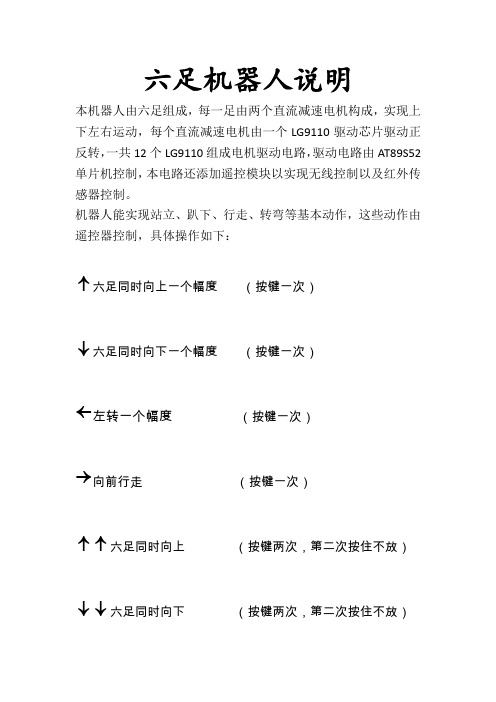
六足机器人说明
本机器人由六足组成,每一足由两个直流减速电机构成,实现上下左右运动,每个直流减速电机由一个LG9110驱动芯片驱动正反转,一共12个LG9110组成电机驱动电路,驱动电路由A T89S52单片机控制,本电路还添加遥控模块以实现无线控制以及红外传感器控制。
机器人能实现站立、趴下、行走、转弯等基本动作,这些动作由遥控器控制,具体操作如下:
↑六足同时向上一个幅度(按键一次)
↓六足同时向下一个幅度(按键一次)
←左转一个幅度(按键一次)
→向前行走(按键一次)
↑↑六足同时向上(按键两次,第二次按住不放)
↓↓六足同时向下(按键两次,第二次按住不放)。
机器人说明提交版doc
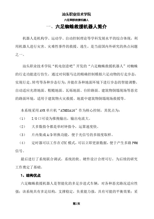
一、六足蜘蛛救援机器人简介机器人是机构学、运动学、自动控制理论等学科发展水平的综合体现,利用机器人进行灾害、灾难性事件的救援、逃生,是当前国内外研究的热点问题之一。
汕头职业技术学院“机电创意吧”开发的“六足蜘蛛救援机器人”对蜘蛛的行走功能进行仿生,通过对伺服马达的精确控制模拟六足动物的行走步态,实现行走、转弯等各种步态行为,并能在各种地面环境下进行步态的智能调整,自动适应光滑地面、粗糙地面、瓦砾地面、台阶路面、建筑物倒塌现场等恶劣的路面环境,适用于建筑物火灾救援、地震中建筑物倒塌现场救援等。
本系统采用AVR单片机“ATMEGA16”作为核心控制,其优点为:(1)I/O口可设为推挽输出,输出电流大。
(2)大多数指令都是单时钟指令,运算速度快。
(3)片内集成A/D转换功能,便于光信号的多级度取样。
(4)定时器可以工作在CTC模式,可以立即更新数据,便于产生多路PWM 信号。
最后进行了系统联合调试,系统的软、硬件设计合理可行,为后续的研究工作奠定了基础。
1、结构优点六足蜘蛛救援机器人是智能化的多足步进式车辆,对各种恶劣路况适应性强;该系统具有多足结构,支撑稳定,负重能力强,具有可能的平衡效果;采用光敏传感器,根据光强自动调整运行方向,作为模型,已经模拟了根据环境情况自动做出动作反映的机器人功能;伺服电动机舵机作为动力,,效率和功率质量比高;单片机控制电路,满足复杂的控制功能,鲁棒性高;机械轮廓设计生动,爬行姿态优美。
拥有传统轮式机器人和履带式机器人无法企及的优势。
2、救援方面的应用(1)此六足机器人可以实现前进、后退、左右转弯等,利用光敏传感器根据环境光线强弱自动控制其行走方向,利用障碍物传感器,实现自动绕越障碍物的功能,并且在火灾中自动寻找火焰确定灭火目标。
(2)此机器人采用多足步进的方式前进,故可在各种复杂地形上爬行,到达轮式机器人和履带是机器人所无法到达斜度很高的斜坡、山地。
(3)在山地、戈壁上帮助驮运救援物资、药品。
arduino仿生六足机器人教材

仿生六足机器人教材———基于Arduino开发平台V1.0目录一、机器人的组装 (1)1.1. 组装工具 (1)1.2. 装配步骤 (1)二、系统概述 (10)2.1.arduino介绍 (10)2.2.Arduino驱动安装 (13)2.3.Arduino IDE菜单介绍 (20)三、实验操作 (25)3.1 红外避障实验 (25)3.2 舵机实验 (27)四、使用说明 (31)4.1.接线端口介绍 (31)4.2.操作说明 (32)一、机器人的组装1.1. 组装工具工具:尖嘴钳、十字螺丝刀等。
1.2. 装配步骤1)首先是准备好机体2)在机体上装配4个M3X15mm的六棱铜柱,所用到4个M3X8mm的螺钉如下图所示:我这里为了方便能够清楚看到螺钉与铜柱的连接把它分开了。
4)下一步就是装两个模拟舵机和付板,所用到八个螺钉,八个螺母如下图所示1是分解装配6)这一步是两个十字舵盘的安装,这里用到两个M3X6mm的螺丝8)组装M3X20mm、M3X25mm的六棱铜柱,这里中间部位是两个M3X20mm六棱铜柱,两侧是M3X25mm的六棱铜柱,用到M3X8mm 的螺丝10)中间脚的组装,M3X20螺丝、M3螺母、钢纸垫片11)组装连接杆12)另一个连杆组装13)两侧脚组装,这里用到M3X8螺丝、M3螺母、钢纸垫片14)固定完成15)中间脚上部螺丝的固定,这里用到M3X8螺丝、钢纸垫片二、系统概述2.1.arduino介绍要了解arduino就先要了解什么是单片机,arduino平台的基础就是A VR指令集的单片机。
1、什么是单片机?它与个人计算机有什么不同?一台能够工作的计算机要有这样几个部份构成:中央处理单元CPU(进行运算、控制)、随机存储器RAM(数据存储)、存储器ROM(程序存储)、输入/输出设备I/O(串行口、并行输出口等)。
在个人计算机(PC)上这些部份被分成若干块芯片,安装在一个被称之为主板的印刷线路板上。
- 1、下载文档前请自行甄别文档内容的完整性,平台不提供额外的编辑、内容补充、找答案等附加服务。
- 2、"仅部分预览"的文档,不可在线预览部分如存在完整性等问题,可反馈申请退款(可完整预览的文档不适用该条件!)。
- 3、如文档侵犯您的权益,请联系客服反馈,我们会尽快为您处理(人工客服工作时间:9:00-18:30)。
六足六足机器人机器人机器人套件使用套件使用套件使用向导向导向导及简单排错
及简单排错这篇是写给基础比较差,对教程内容不能很好理解而又急于做成的新手。
套件为教程而生,教程却不局限于套件,教程具有通用性,启发性,流传性。
网店的套件统一用特性规格的纸盒包装,里面内容如下图。
不同时期,不同清单会有区别,以实际为准。
电控部分对于新手来说比较复杂,先来认知一下各个模块(下图)。
Usb蓝牙适配器:用于与舵机板的蓝牙串口通讯,详细操作见《24路舵机控制板使用说明》内蓝牙调试一节。
红外避障模块:用在六足机器人的外界感知反馈。
详细操作见教程《智能篇----红外避障》。
STC51单片机主控:作为六足的大脑,负责全局控制,控制传感器,控制动作等等,详细操作见教程智能篇几篇。
对于单片机的使用,建议没有单片机编程基础的新手先去网上了解串口的定义,使用;keil的使用;51单片机C 语言的编写;查看特定单片机型号的数据手册等。
24路舵机控制器:用于六足机器人各个舵机的驱动控制,配有PC端调试软件,方便调试每一步动作,大大简化
了对六足步态的分析,管理,推算。
详细操作见《24路舵机控制板使用说明》。
各个模块需要各种连接线也要介绍一下(下图)。
3P通讯线:用来舵机控制器与usb串口模块连接,然后与PC通讯。
连接如下图
注意不要看颜色来接线,套件线材都是使用的彩排线,颜色是随机的。
3P连接线:用于红外避障模块与STC51单片机主控连接,连接如下图
4P通讯线:用于STC51主控与舵机控制器通讯连接,连接如下图
3P红外接收头连接线:用于红外接收头与STC51主控的连接,连接如下图
注意:不要盲目看图,仔细辨认红外接收头的引脚标识。
4P下载线:用于STC51单片机主控与usb串口模块连接,PC端STC-ISP软件下载程序。
连接如下图
各个模块的简单排错
舵机:舵机一般常见的故障为,电路短路,元件烧毁,齿轮断齿。
有时候电路短路是因为图上的3根线的焊点脱落接触,如果是则需要重新上锡焊接。
元件烧毁并不一定外观有损坏,元件内部构造被瞬间击穿而外观无损也是经常发生的。
齿轮断齿是比较好分辨的,只需将坏的齿轮更换掉就行了,还有一点,使用时间长的舵机齿轮会磨损,造成大范围角度的抖动,这时更换一套新的齿轮组可以让舵机焕然一新。
舵机控制板:由于裸露的引脚过多,所以首先必须要注意的是避免任一两个引脚短接造成的短路,正面和背面都要注意,包括舵机内部电路的短路,STC51板通讯端的短路,usb串口通讯端的短路。
舵机控制板常见的故障有无法与PC端调试软件通讯,
无法调试舵机或某一路舵机,
电池给舵机板供电无反应指示灯不亮,
舵机突然不听使唤抽搐等。
如果出现这些问题,请用万用表
检测通讯线是否接触不良或短接,
检测舵机所在的路数对应的引脚是否与GND短路,对应芯片引脚是否短路,虚焊,
检测舵机板上VCC与GND是否短路,
测量供电时舵机电压等
出现自己无法解决的问题请联系卖家,寄回维修。
STC51单片机主控:常见的故障有
无法下载程序,
下载程序后执行错误,
无法与舵机控制板通讯,
板子芯片发热大等
无法下载程序是STC51单片机的通病,在网上经常会遇到网友抱怨不同型号的STC51无法下载程序。
官方至今也无法给出一劳永逸的解决方案。
虽然缺点是有,但优势仍然存在,便宜,易用性。
通过我几台电脑几年的使用情况来看,稳定的系统是保证下载成功的前提条件,众所周知,国人喜欢用盗版系统,而且现在盗版系统安装也方便,傻瓜式一键安装,笔者在做公司IT的时候就为公司做过专用系统的封装与部署。
这种定制系统存在一个问题,一些定制者喜欢删除,简化不常用的系统组件,只保留常用组件,美名曰精简版系统,让您的电脑运行速度更快。
这样做确实有一定的道理,但对使用专业工具软件的人却是个灾难,系统组件丢失或不存在会造成专业工具软件无法运行,报错,无响应,不执行等等问题,用户层并不一定看的到。
所以安装纯净完全版系统对技术爱好者是十分必要的。
Usb串口模块的驱动安装不正确也会引起无法下载程序,插上usb串口模块,在设备管理器里查看对应的com端口数,波特率尝试最高和最低统一,或者最快速的方法就是换台电脑下载。
下载程序后执行错误分两方面吧,keil编写程序严格区分全角半角,注意代码复制进去产生的怪异乱码,空格,换
行等等。
二是自己修改程序,逻辑顺序不通,或字符,语句有误,造成单片机无法正确执行。
无法与舵机控制板通讯一般是舵机控制板的问题,通讯线也要检测是否接触不良。
板子芯片发热大,芯片烧了,或者负责外部供电的跳冒开关没拔掉。
暂时说这些吧,以后有问题继续补充。
网店
博客
群广场/135819。