(日本东北大学固体物理学课件)Structure of Solids
固体物理 1-3东师课件

r0
体 对 角 线
a
△=0.31r0
4 r0 3a a 2 r0
结论:体心立方晶格一个平面内的原子球并不是最紧密排列。
最紧密的堆积方式
密排面
原子球必须与同一平面内相邻 的6个原子球相切
3a0 4r
2a0 4r
a0 2r
原胞及原胞基矢
(primitive cell and unit vector)
定义:一个晶格中最小的周期性单元称原胞。
a2 a1 a2 a1
a2 a1
a1
ห้องสมุดไป่ตู้
a2
a2
a1
原胞及基矢的选取——不唯一
晶格基矢(unit vector) 即原胞的边矢量; 一般用 a , a 来表示。 ,a
π X= 0.52 6
1 1 2 1 4 1 8
体心立方结构空间占有率
4 R 3a 4 3 2 R 3 X 3 a
X=
3π 0.68 8
面心立方结构空间占有率
4 R 2a 4 3 4 R 3 X 3 a
2 X 0.74 6
1 2 3
k 简立方、体心立方和面心立方晶格的原胞和基矢
j
i
v0 a3 / 2 v0 a3
简立方结构原胞 =a a1 a2 =a
i j k
体心立方原胞
=a/2( a1 a2 =a/2(
) k i j i j ) k i )j k
最紧密堆积的类型
A型空隙 B型空隙
《固体物理学教案》课件
《固体物理学教案》PPT课件一、教案简介本教案旨在帮助学生了解和掌握固体物理学的基本概念、原理和应用。
通过本课程的学习,学生将能够理解固体物质的结构、性质以及其宏观表现,为进一步研究相关领域打下坚实基础。
二、教学目标1. 了解固体物理学的基本概念和研究方法。
2. 掌握晶体结构、电子分布、能带结构等基本内容。
3. 理解固体物理学的宏观性质及其微观解释。
4. 熟悉固体物理学在材料科学、凝聚态物理等领域的应用。
三、教学内容1. 固体物理学概述固体物理学的基本概念固体物理学的研究方法2. 晶体结构晶体的基本概念晶体的分类与空间群晶体的生长与制备3. 电子分布与能带结构电子分布的基本理论能带结构的类型及特点能带的调控与应用4. 固体物理学的宏观性质导电性、热导性、光学性质磁性、超导性、半导体性质力学性质与缺陷化学5. 固体物理学在实际应用中的案例分析材料科学与固体物理学凝聚态物理与固体物理学纳米技术、量子计算等领域中的应用四、教学方法1. 采用PPT课件进行讲解,结合实物图片、动画等直观展示,提高学生的学习兴趣和理解能力。
2. 通过案例分析、讨论等形式,激发学生的思考和创新能力。
3. 布置适量的课后习题,巩固所学知识,提高学生的实际应用能力。
五、教学评价1. 课后习题完成情况:评价学生对固体物理学基本概念和原理的掌握程度。
2. 课堂讨论参与度:评价学生在讨论中的表现,包括思考问题、表达能力等。
3. PPT课件制作与讲解:评价学生对固体物理学知识的理解和运用能力。
4. 期末考试:全面测试学生对固体物理学知识的掌握和应用能力。
六、教案设计6. 晶体的基本性质晶体粒子的排列与周期性晶体的对称性晶体的力学性质晶体的热性质7. 电子态与能带理论电子在晶体中的分布能带理论的基本概念能带的类型与特性能带结构与材料性质的关系8. 固体能谱学X射线衍射与晶体学电子显微学光学光谱学核磁共振谱学9. 磁性材料磁性的基本类型磁畴与磁化过程磁性材料的性质磁性材料的应用10. 结论与展望固体物理学的发展历程当前固体物理学的研究热点固体物理学在未来的发展趋势固体物理学对人类社会的贡献七、教学策略6. 通过实物模型和显微镜观察晶体结构,增强学生对晶体对称性和排列规律的理解。
《固体物理能带理论》课件

探索禁带宽度
禁带宽度的影响
深入探究禁带宽度对材料性质的 影响,介绍如何利用禁带宽度调 控材料性质。
直接/间接带隙
介绍直接带隙和间接带隙的概念 和特点,以及如何通过调控禁带 宽度实现它们之间的转换。
量子点
了解量子点的概念及其在光伏、 光催化、发光等方面的应用。
电子在周期势场中的行为
布拉歇特条件
探究布拉歇特条件的作用和意义,以及如何通过布拉歇特条件来理解材料导电性。
电子自旋
介绍电子自旋的概念和特点,以及在磁性材料中的重要作用。
量子霍尔效应
了解量子霍尔效应的概念和特点,以及其在电子学、自旋测量等方面的应用。
应用能带理论
1
太阳能电池
探究太阳能电池的原理和构造,以及如
半导体激光器
2
何利用能带理论来提高太阳能电池的性 能。
介绍半导体激光器的原理和构造,以及
如何通过能带理论来优化激光器的性能。
《固体物理能带理论》 PPT课件
通过本PPT了解固体物理能带理论,理解能带的概念和特点,并探究能带理论 在实际应用中的应用。
什么是固体物理能带理论?
晶体的电子结构
介绍晶体的基本结构和存在能带 的原因,以及能带分布的规律。
能带、狄拉克相对论
进一步探究能带的特点及其与材 料导电性的关系,介绍狄拉克相 对论的意义。
Bloch定理和能带图
介绍Bloch定理的作用,以及如何 通过能带图来描绘材料的电子结 构。
深入理解价带和导带
价带的物理意义
介绍价带中电子的特征和性 质,并探讨不同能级之间的 关系。
导带的物理意义
深入剖析导带中的电子行为, 介绍电子元件中导带的作用。
轻重空穴带
固体的晶体结构solid_state_structures
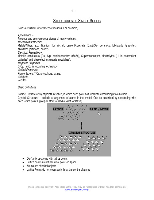
S TRUCTURES OF S IMPLE S OLIDSSolids are useful for a variety of reasons. For example,Appearance –Precious and semi-precious stones of many varieties.Mechanical Properties –Metals/Alloys, e.g. Titanium for aircraft, cement/concrete (Ca3SiO5), ceramics, lubricants (graphite), abrasives (diamond, quartz).Electrical Properties –Metallic conductors (Cu, Ag), semiconductors (GaAs), Superconductors, electrolytes (LiI in pacemaker batteries) and piezoelectrics (quartz in watches).Magnetic Properties –CrO2, Fe3O4 in recording technology.Optical Properties –Pigments, e.g. TiO2, phosphors, lasers.Catalysts –ZeolitesBasic DefinitionsLattice – infinite array of points in space, in which each point has identical surroundings to all others. Crystal Structure – periodic arrangement of atoms in the crystal. Can be described by associating with each lattice point a group of atoms called a Motif (or Basis).•Don't mix up atoms with lattice points•Lattice points are infinitesimal points in space•Atoms are physical objects•Lattice Points do not necessarily lie at the centre of atomsUnit Cell – smallest component of the crystal, which when stacked together with pure translational repetition reproduces the whole crystal.Primitive (P) unit cells contain only a single lattice point.2D Latticese.g. Graphite:Counting Lattice Points –Unit cell is primitive, but contains two atoms in the motif.Atoms at the corner contribute only ¼ to unit cell count.Atoms at the edge contribute only ½ to unit cell count.Atoms within the unit cell contribute 1 to unit cell count.Analysing in 3D:Graphite = staggered arrangement of stacked hexagonal layers.Unit cell dimensions:a, b, c = unit cell lengthsα, β, γ = angles (α = angle between b and c, etc.)Counting atoms in 3D:Edge contributes = ¼Vertex contributes = 1/8Face contributes = ½Body contributes = 1On combining 7 Crystal Classes with 4 possible unit cell types, symmetry indicates that only 14 3D lattice types occur. These are the Bravais Lattices.These are depicted below (note that spheres = lattice points, not atoms!)Combining these 14 lattices with all the possible symmetry elements means there are 230 different Space Groups.Close Packing of SpheresGoldschmidt (1926) proposed atoms could be considered by packing of hard spheres. Thus it makes sense to examine the most efficient packing system of any spherical object. A single layer of spheres is closest-packed with a hexagonal coordination of each sphere. A second layer is placed in the indentations in the first layer. Space is trapped between the layers that is not filled by spheres. Two different types of holes (interstitial sites) are left:•Octahedral (O) holes with 6 nearest neighbours.•Tetrahedral (T±) holes with 4 nearest neighbours.When a third layer is placed in the indentations there are two possibilities:•The third layer lies directly in line (eclipsed) with the 1st layer (ABABABAB)•The third layer lies in the alternative indentations leaving it staggered with respect to both previous layers (ABCABCABC).Features of Close PackingCoordination Number is 12, with 74% of space occupiedLargest interstitial sites are:octahedral (O) ( r = 0.414) ~ 1 per spheretetrahedral (T±) (r = 0.225) ~ 2 per sphereSimplest Close Packing Structures:ABABAB.... repeat gives Hexagonal Close-Packing (HCP)Unit cell showing the full symmetry of the arrangement is Hexagonal Hexagonal: a = b, c = 1.63a, a = b = 90°, g = 120°2 atoms in the unit cell: (0, 0, 0) (2/3, 1/3, 1/2)ABCABC.... repeat gives Cubic Close-Packing (CCP)Unit cell showing the full symmetry of the arrangement is Face-Centred Cubic Cubic: a = b =c, a = b = g = 90°4 atoms in the unit cell: (0, 0, 0) (0, 1/2, 1/2) (1/2, 0, 1/2) (1/2, 1/2, 0)A non-close packed structure adopted by some is BCC:Metal structures adopted:Polymorphism –Some metals exist in different structure types at ambient temperature and pressure.Many metals adopt different structures at different temperature and pressure.Different structures occur because of residual effects from atomic orbitals. It is complicated to predict structures. Best explanations for structure are based on Band Theory of Metals.BCC is clearly adopted for low number of valence electrons. In polymorphism, BCC is adopted at higher temperatures.More complex structures than simple HCP and CCP are possible.Location of Interstitial Holes in Close-Packed StructuresThe holes may be filled with different atoms. It is important to know how holes are displaced relative to the positions of the spheres and relative to each other.Octahedral Holes:Tetrahedral Holes –Arrangement of Nearest Neighbours about a Sphere –Ionic (and other) structures may be derived from the occupation of interstitial sites in close-packed arrangements:Some binary structures derived from hole filling by one type of atom in CCP and HCP arrangements of another:Formula Type & occupation CCP HCPAB AlloctahedralNaClRock SaltNiAsNickel ArsenideHalf tetrahedral (T+ orT-)ZnSZinc Blende(Sphalerite)ZnSWurtziteAB2 Alltetrahedral Na2O Anti-FluoriteCaF2 Fluoritenot knownAB3All octahedral &tetrahedralLi3Bi notknownA2BHalf octahedral(Alternate layersfull/empty)CdCl2(Cadmium Chloride) CdI2(Cadmium Iodide)Half octahedral(Ordered frameworkarrangement)TiO2(Anatase)CaCl2TiO2(Rutile)A3BThird octahedral.Alternate layers 2/3full/emptyYCl3 BiI3Polyhedral Representations:Defining the coordination environment of an ion as a polyhedron (octahedron or tetrahedron). Can represent structures by linking polyhedra together.S TRUCTURAL T YPESStructures from Cubic Close packingNaCl (rock salt) –•CCP Cl- with Na+ in all octahedral holes.•Lattice = FCC.•Motif = Cl at (0,0,0); Na at (1/2,0,0)• 4 NaCl in the unit cell.•Coordination 6:6 (octahedral).•Cation and anion sites are topologically identical.CaF2 (fluorite) / Na2O (antifluorite) –•CCP Ca2+ with F- in all Tetrahedral holes•Lattice: FCC•Motif: Ca2+ at (0,0,0); 2F- at (1/4,1/4,1/4) & (3/4,3/4,3/4)•4CaF2 in unit cell•Coordination: Ca2+ 8 (cubic) : F- 4 (tetrahedral)•In the related Anti-Fluorite structure Cation and Anion positions are reversed ZnS (Zinc Blende) –•CCP S2- with Zn2+ in half Tetrahedral holes (only T+ {or T-} filled)•Lattice: FCC•4ZnS in unit cell•Motif: S at (0,0,0); Zn at (1/4,1/4,1/4)•Coordination: 4:4 (tetrahedral)•Cation and anion sites are topologically identicalExamples of Structure Adoption –NaCl –•Very common (inc. 'ionics', 'covalents' & 'intermetallics' )•Most alkali halides (CsCl, CsBr, CsI excepted)•Most oxides / chalcogenides of alkaline earths•Many nitrides, carbides, hydrides (e.g. ZrN, TiC, NaH)CaF2 –•Fluorides of large divalent cations, chlorides of Sr, Ba•Oxides of large quadrivalent cations (Zr, Hf, Ce, Th, U)Na2O –•Oxides /chalcogenides of alkali metalsZnS (Zinc Blende) –•Formed from Polarizing Cations (Cu+, Ag+, Cd2+, Ga3+...) and Polarizable Anions (I-, S2-, P3-, ...);Cu(F,Cl,Br,I), AgI, Zn(S,Se,Te), Ga(P,As), Hg(S,Se,Te)Structures Derived From Hexagonal Close PackingNiAs (Nickel Arsenide) –•HCP As with Ni in all Octahedral holes•Lattice: Hexagonal - P•Motif: 2Ni at (0,0,0) & (0,0,1/2) 2As at (2/3,1/3,1/4) & (1/3,2/3,3/4)•2NiAs in unit cell•Coordination: Ni 6 (octahedral) : As 6 (trigonal prismatic)ZnS (wurtzite) –•HCP S2- with Zn2+ in half Tetrahedral holes (only T+ {or T-} filled) •Lattice: Hexagonal - P•Motif: 2S at (0,0,0) & (2/3,1/3,1/2); 2Zn at (2/3,1/3,1/8) & (0,0,5/8)•2ZnS in unit cell•Coordination: 4:4 (tetrahedral)Comparing Wurtzite with Zinc Blende –CdI2 (Cadmium Iodide) –HCP Iodide with Cd in octahedral holes of alternate layers.•Lattice: Hexagonal - P•Motif: Cd at (0,0,0); 2I at (2/3,1/3,1/4) & (1/3,2/3,3/4)•1CdI2 in unit cell•Coordination: Cd - 6 (Octahedral) : I - 3 (base pyramid)Polyhedral representation is informative –Examples of Structure Adoption –NiAs:•Transition metals with chalcogens, As, Sb, Bi e.g. Ti(S,Se,Te); Cr(S,Se,Te,Sb);Ni(S,Se,Te,As,Sb,Sn)CdI2:•Iodides of moderately polarising cations; bromides and chlorides of strongly polarising cations; e.g.PbI2, FeBr2, VCl2•Hydroxides of many divalent cations e.g. (Mg,Ni)(OH)2•Di-chalcogenides of many quadrivalent cations e.g. TiS2, ZrSe2, CoTe2CdCl2 (CCP equivalent of CdI2):•Chlorides of moderately polarising cations e.g. MgCl2, MnCl2•Di-sulfides of quadrivalent cations e.g. TaS2, NbS2 (CdI2 form as well)•Cs2O has the anti-cadmium chloride structureHCP CaF2 analogue?No structures known with all tetrahedral sites filled in HCP. To explain this we note that the T+ and T- interstitial sites above and below a layer of close-packed spheres in HCP are too close to each other to tolerate the coulombic repulsion generated by filling with like-charged species.Non-close Packed Structures –Caesium Chloride:•Lattice: Cubic - P (N.B. Primitive!)•Motif: Cl at (0,0,0); Cs at (1/2,1/2,1/2)•1CsCl in unit cell•Coordination: 8:8 (cubic)•Adoption by chlorides, bromides and iodides of larger cations, e.g. Cs+, Tl+, NH4+MoS2 (molybdenite) –•Note: Hexagonal layers of S atoms are NOT Close-packed in 3D•Lattice: Hexagonal - P•Motif: 2Mo at (2/3,1/3,3/4) & (1/3,2/3,1/4) , 4I at (2/3,1/3,1/8), (2/3,1/3,3/8), (1/3,2/3,5/8) & (1/3,2/3,7/8) •2MoS2 in unit cell•Coordination: Mo 6 (Trigonal Prismatic) : S 3 (base pyramid)Comparing MoS2 and CdI2:Diagrams indicate that both are layer structures, with edge linked layers. However, MoS2 is linked by trigonal prisms, while CdI2 is by octahedra.Comparing MoS2 and NiAs –•S in MoS2 / Ni in NiAs are hexagonal close-packed 2D layers•These layers do not stack in close-packed 3D sequenceso Ni layers in NiAs stack directly above each other in an AAAA... fashiono S layers in MoS2 stack in an AABBAABB ... fashion•Two hexagonal layers directly above each other leave TRIGONAL PRISMATIC interstitials o 2 per sphere•In NiAs, As fills half the trigonal prismatic sites between all layers of Ni, in a layer sequence bcbcbc...•In MoS2 Mo also fills alternate trigonal prismatic sites where they occuro Trigonal prismatic sites only occur between directly stacked layers (AA or BB)o Adjacent S layers with an AB sequence have no Mo inbetween & interact by van der Waals forces•MoS2 cannot be described in terms of interstitial filling of a close-packed structure•NiAs can be described as HCP As with Ni in octahedral holesMetal Oxide StructuresRutile, TiO2 –•Unit Cell: Primitive Tetragonal (a = b ¹ c)•2TiO2 per unit cell•Motif: 2Ti at (0, 0, 0); (1/2, 1 / 2, 1 /2) & 4O at ±(0.3, 0.3, 0); ±(0.8, 0.2, 1 /2)•Ti: 6 (octahedral coordination)•O: 3 (trigonal planar coordination)•TiO6 octahedra share edges in chains along c•Edge-sharing Chains are linked by vertices•Examples: oxides: MO2 (e.g. Ti, Nb, Cr, Mo, Ge, Pb, Sn), fluorides: MF2 (e.g. Mn, Fe, Co, Ni, Cu, Zn, Pd)Rhenium Trioxide, ReO3 –•Lattice: Primitive Cubic•1ReO3 per unit cell•Motif: Re at (0, 0, 0); 3O at (1/2, 0, 0), (0, 1/2, 0), (0, 0, 1/2)•Re: 6 (octahedral coordination)•O: 2 (linear coordination)•ReO6 octahedra share only vertices•May be regarded as ccp oxide with 1/4 of ccp sites vacant (at centre of the cell). Defective FCC of O atoms (a face O is missing).•Examples:o WO3 , AlF3 , ScF3 , FeF3 , CoF3 , Sc(OH)3 (distorted)Perovskite, CaTiO3 –•Lattice: Primitive Cubic (idealised structure)•1CaTiO3 per unit cell•A-Cell Motif: Ti at (0, 0, 0); Ca at (1/2, 1/2, 1/2); 3O at (1/2, 0, 0), (0, 1/2, 0), (0, 0, 1/2)•Ca 12-coordinate by O (cuboctahedral)•Ti 6-coordinate by O (octahedral)•O distorted octahedral (4xCa + 2xTi)•TiO6 octahedra share only vertices•CaO12 cuboctahedra share faces•Ca fills the vacant CCP site in ReO3, Þ a CaO3 ccp arrangement with 1/4 of octahedral holes (those defined by 6xO) filled by Ti•Examples: NaNbO3 , BaTiO3 , CaZrO3 , YAlO3 , KMgF3•Many undergo small distortions: e.g. BaTiO3 is ferroelectricThe perovskite structure is fully predicted by Pauling’s 2nd Rule (see below).Rationalisation of Ionic StructuresPrinciples of Laves1.Space Principle – space is used most efficiently.2.Symmetry Principle – highest possible symmetry is adopted.3.Connection Principle – there will be the most possible “connections” between components (i.e.coordination numbers are maximised).This is followed by metals and inert gases – close-packed structures. However, deviations include BCC metals.Ionic compounds strive to follow the principles, but to an extent are modified by any specific directional bonding interactions, size differentials and stoichiometric concerns.The Ionic Model by Goldschmidt states that are ions are essentially charged, incompressible, non-polarisable spheres. More sophisticated models assume ions are composed of two parts:A central, hard, unperturbable core, where most electron density is concentrated.A soft, polarisable outer sphere, which contains very little electron density.Pauling’s RulesStructural principles for ionic crystals were summarised by Pauling in a series of Rules. They have been widely used and are still useful in many situations.Rule 1: Coordination PolyhedraA coordination polyhedron of anions is formed around every cation (and vice-versa) – it will only be stable if the cation is in contact with each of its neighbours.Ionic crystals may thus be considered as sets of linked polyhedra. The cation-anion distance is regarded as the sum of ionic radii.Valency has only an indirect bearing on coordination number, but ionic size does influence coordination number. This lead to the Radius Ratio Rules, as the coordination number of the cation will be maximised subject to the criterion of maintaining anion-cation contact. This can be determined by comparison of the ratio of r+ to r-.Limiting Radius Ratios –Radius Ratio Coordination no.Binary (AB) Structure-type r+/r- = 1 12 none known1 > r+/r- > 0.732 8 CsCl0.732 > r+/r- > 0.414 6 NaCl0.414 > r+/r- > 0.225 4 ZnSIonic Radii scales do not generally meet at experimental electron density minima, because of polarisation of the anion by the cation. Also, ionic radii change with coordination number.Using the rules however, shows that they do not work very well. Mainly, it suggests that the CsCl structure should be adopted more often that actually happens. In fact only correct about 50% of the time – might as well guess!Reason for the failing is that structure adoption is not just due to the Goldschmidt anion-cation contact Criterion.Consider Lattice Energy – highest possible coordination number is adopted due to greater Madelung Potentials.Structure Type Madelung ConstantCsCl 1.763NaCl 1.748ZnS (Wurtzite ) 1.641ZnS (Zinc Blende ) 1.638Madelung Energy is seen to rise as r+/r- falls, until the structure can no longer support cation-anion contact. At the geometrically limiting radius ratio – the Madelung Energy remains constant (limit of anion-anion contact).Born-Lande –)11(42nr e z NAz U o L −=−+πεA = Madelung Constant. Additional electrostatic interaction energy from 3D lattice of ions. Depends purely on structure.From this, the Kapustinskii Equation –−+−++=r r z Cvz U L 1) A/v is constant. 2) r = r + + r - (pm)3) average value of N = 9.No need for the structure to be known. Good for comparisons (e.g. ionic vs. covalent character). Can work out radii from experimental U L as well.Consequences of this –CsCl is never adopted unless 8:8 coordination maximises dispersion forces. Also covalency in NaCl due to Cl - 3 p-orbitals.Note that as pressure is increased, CsCl structure is favoured. This is because high coordination number is favoured in order to put the limited volume to full use. Also it dehybridises large ions such that directional bonding effects are lost.Structure Maps show that size does matter, but the boundaries are complicated (i.e. the Radius Ratio rules are too simplistic to ever be able to rationalise).Rule 2 – Electrostatic Valence Principle (Bond Strength)In a stable ionic structure the charge on an ion is balanced by the sum of electrostatic bond strengths to the ions in its coordination polyhedron, i.e. a stable ionic structure must be arranged to preserve local electroneutrality (ions in a crystal are surrounded by ions of opposite charge so as not to produce large volumes of similar charge in the crystal - this maximizes Madelung potential!).Rule 3 – Polyhedral LinkingThe stability of structures with different types of polyhedral linking is:Vertex > edge > face.Effect is largest for cations with high charge and low coordination number. Especially large when r+/r- approaches the lower limit of polyhedral stability.Sharing edges/faces brings the ions at the centre of each polyhedron closer together, hence increasing electrostatic repulsions, i.e. disposition of ions of similar charge will be such as to minimise the Electrostatic Energy between them.This rule is obeyed by compounds of high polarity (e.g. fluorides, oxides), but not those with lower polarity. Other compounds are directly contrary to it, e.g. NiAs – face-sharing stabilises due to Metal-Metal bonding. Rule 4 – Cation Evasion in mixed compounds (not Binaries)In a crystal containing different cations those of high valency and small coordination number tend not to share polyhedral elements with each other.e.g. Perovskite, CaTiO3.Ca II 12 coordinate, shares FACESTi IV 6 coordinate, shares only VERTICESRule 5 – Environmental HomogeneityThe number of essentially different kinds of constituent in a crystal tends to be small, i.e. as far as possible, similar environments for chemically similar atoms.This is, however, often not obeyed.When Pauling’s Rules are not obeyed, this suggests special structural influences in the bonding.Indirect evidence for non-ionic structures are increasing polarisation in bonding, and low dimensionality (layers, chains).Fajan’s RulesPolarisation will be increased by:1. High charge and small size of the cation. Ionic potential Å Z+/r+ (= polarizing power)2. High charge and large size of the anion. The polarisability of an anion is related to the deformability of its electron cloud (i.e. its "softness")3. An incomplete valence shell electron configuration. Noble gas configuration of the cation better shielding less polarizing power, i.e. charge factor in (1) should be effective nuclear charge , e.g. Hg2+ (r + = 102 pm) is more polarising than Ca2+ (r+ = 100 pm)Bond Directionality / Extent of CovalencyElectronegativity defined by Pauling as “the power of an atom in a molecule to attract electrons to itself”. Bonding type depends on the difference in electronegativity between the elements involved.Mooser-Pearson Plots combine bond directionality, size and electronegativity in Structure Maps.Beyond that, there are many other factors that influence structure adoption, particularly when looking at Transition Metal and Non-metal solids (i.e. non-ionic).Compare and contrast the crystal structures adopted by either fluorides and chlorides or oxides and sulphides of the metallic elements.Fluorides and ChloridesFluorides tend to differ from other halides due to Fluorine’s extreme electronegativity and small size, making it much less polarisable than the others. Pauling’s scale gives an electronegativity value of 4.0 for F, the highest of any element. Hence it shows high coordination numbers (due to greater lattice energy generated) and does not form layers. This is similar for O2-.Despite this, structures for the chlorides and fluorides are often similar. This is particularly the case for the alkali metals, and is presumably due to their reluctance to occupy more complex structures due to the limited valence electron availability (they are essentially an inert core with 1 electron available for bonding/transfer). Thus they have very high ionic character for Group 1 & 2, although this does not apply for transition and post-transition metals.Hence we would expect to see the more ionic structures for the alkali metals, such as rock salt. Also, for Group 2 metals that are not very large, fluorite structures are expected (e.g. CaF2).However, moving across the periodic table sees a change in the tendencies to form these ionic structures. Typically a drop in coordination number is seen as the ionic radius falls across the periods (due to Z eff increasing as n rises but d electrons do not penetrate sufficiently to counteract it). More directional bonding results, and structures such as Zinc Sulphide and Rutile are preferred.The chlorides show a less strong ionic tendency and are larger, so it is expected that these latter structures are more likely here. For example, CaF2 is fluorite, while CaCl2 will form the rutile structure (with lower coordination) because Cl- is larger. There is also the possibility of π-donation from Cl- strengthening the bonds, but only for Transition Metals.However, when looking at the Chlorides, there are also other structures which emerge. This is because the polarisability of Cl- allows for stabilising dispersion forces to operate and other structures are thus possible (and indeed favoured). These tend to be formed from layers or chains, reflecting the increased covalency in bonding. These are typified by the CdCl2 and CdI2 layer structures (the only difference being that CdI2 ishexagonally close packed while CdCl2 is cubic). It is seen from the structure that there is significant anion-anion contact, therefore a polarisable (i.e. covalent) anion is needed to be stable.Oxides and SulphidesIn a similar way to Fluorine, Oxygen differs greatly in its electronegativity and size when compared to Sulphur. Thus Fluorides and Oxides often have similar structures for the same metals, and where stoichiometries are equivalent the compounds are often isostructural. Sulphur on the other hand is large and polarisable, so we would expect to see similar trends to those observed for Chlorides, i.e. a greater significance placed on covalent interactions.Metal-Oxides bonds tend to be more ionic due to the electronegativity difference, so ionic sulphides only form with electropositive metals (i.e. Groups 1 & 2) and when the metal’s charge is low (e.g. lower than M3+, except Al2S3). When they do form, they show similarities to metal oxide structures, e.g. MnS and MnO are similar.For example, TiO2 is the classic rutile structure. Ti4+ is highly polarising, so we would expect a strong degree of covalency present. It shows O2- with 3 x trigonal planar Ti, as depicted earlier. However, TiS2 is completely different, with 3 x pyramidal bonds in layers.S2- does not exist with M4+ (non-ionic), but will instead form layers with S22- groups (disulphide ions). This does not form for Oxygen with Transition Metals, due to lone pair / lone pair repulsions from the much smaller O atoms being closer to one another. However, Oxygen will form peroxides and superoxides with large alkali metals, which are also O2 ions. Sulphur does not favour this so much, presumably preferring to catenate with several covalent bonds in a similar manner to solid sulphur (S8 units) compared to O2(g).Note that the differences in structure are sometimes so extreme that oxides may form when sulphides do not, or vice versa. For example, PbO2 forms a rutile structure (ionic), but PbS2 does not form easily (Pb IV is not particularly stable – lone pair effect). In reverse, FeS2 is a stable pyrites with S2 groups as described above (based on NaCl), but FeO2 does not exist (Fe4+ is very unstable, and O does not favour covalency).Considering now the typical range of Oxides formed by most metals, the structures can usually be grouped according to stoichiometry because oxides favour the ionic model greatly, so there are less deviations.M2O (Group 1 metals) tend to be anti-fluorite structures, e.g. Na2O. This is also generally true for the sulphides because, even though sulphur does not necessarily favour ionic compounds, M+ for Group 1 is highly ionic and this overrides the covalent tendencies of S. Cs2O is an exception however, and forms an anti-CdX2 structure due to polarisability of Cs+ (unusual for a cation, but Cs+ is extremely large and therefore deformable).MO tend to form rock salt structures (particularly for Group 2 metals) or ZnS structures when the metal is smaller and sterics become important (ZnS structures are 4 coordinate instead of 6). ZnS is also favoured by Transition Metals because there is a higher degree of dispersion forces in effect, and this is stabilising when there is more polarisation (which is suitable for Transition Metals because of their higher valence electron count). There is no metal oxide with the NiAs structure due to the high Madelung Constant for O (too ionic).Comparison with the sulphides shows great variety, particularly for the Transition Metals, e.g. CuO (zinc blende) compared to CuS (unusually complicated), and FeO, NiO, CoO favouring rock salt structure while FeS and CoS forming Nickel Arsenide structure (i.e. more metal-metal bonding and generally greater dispersion forces in operation due to face-sharing).NiS is in fact 5:5 coordinate, and bears no resemblance to the above. In fact, many transition metal sulphides resemble alloys in their structures. Structures can also be temperature dependent, e.g. NiO has the rock salt structure at high T but lowers symmetry at low temperatures.Note that CuO, AgO, PdO and PtO are not typical metal oxide structures, but in fact are isostructural with their MS counterparts. They tend to favour directional bonding (either collinear or planar depending on their d electron counts and hybridisation).MO2 compounds favour fluorite and rutile structures (i.e. ionic). MO3 is typically the Rhenium Trioxide structure. This is very similar for the fluorides, emphasising the likeness of their structural chemistry. These structures do tend to distort, particularly for large metals such as 2nd/3rd row TM’s.M2O3 is usually based on the corundrum structure, although there are exceptions, such as Mn2O3 (see later on). M3O4 is a little rarer, and often forms the spinel structures. These can be normal spinels, as in MgAl2O4, or inverse spinels (energetically less favoured unless there are particularly significant Crystal Field Stabilisation Energies in effect).Sulphides, as expected, favour layered structures more so than the metal oxides above. Some examples are:•TiS2 (CdI2 structure).•TaS2 (CdCl2 structure).•MoS2 .In what ways do the compounds of transition and post-transition metals embraced by your choice show special features in their structures?Considering the effect of the metal on these structures involves separating the periodic table up into essentially 3 Groups.Alkali metals from Groups 1 & 2 are the simplest to discuss, because they are essentially ionic and so structure adoption is usually governed by maximising coordination number (electrostatic lattice energy is largest when there are more bonds) while at the same time reducing steric repulsion (which acts to counteract the energy gained from bond formation). This allows their structures to be predicted more easily, particularly as their radii increase steadily down the groups. This actually explains why the fluorides and oxides tend to show the same structures – the ionic model is working.Transition Metals and post-Transition Metals can also be grouped separately, although there are more factors to consider here, including the ones for alkali metals above.Considering firstly the Transition Metals, it is known that there are often many valence d-electrons present, as opposed to a hard central core of electrons as seen for the alkali metals. These d-electrons are capable。
固体物理第一章(3)(课堂PPT)

1.2 一些晶格的实例
晶格:晶体中原子排列的具体形式称为晶体格子,简称晶格。 (1)晶体原子规则排列形式不同,则有不同的晶格结构; (2)晶体原子规则排列形式相同,只是原子间的距离不同, 则它们具有相同的晶格结构。
处理方法:把晶格设想成为原子球的规则堆积
一、正方堆积
把原子视为刚性小球,在二维平面内最 简单的规则堆积便是正方堆积;
20世纪开始,电子论有很大的发展,对固体的电学、磁性、 光学性质发展了理论,然而是较简单的。由于X射线的发现, 对原子结构有了很好的了解,并且用X射线研究了原子排列, 使得对原子如何结合成为晶体的认识大大深入了一步。量子力 学提高了经典的电子论,使得更深刻地理解固体的电学、磁学、 光学性质。此外,技术的发展大大利用了固体的性质。
任一个球与同一平面内的四个最近邻相 切。
原子球的正方堆积
二、简单立方堆积
正方排列层层重合堆积起来,就构成了简单立方结构
原子球的正方排列
简立方结构单元
没有实际的晶体具有简单立方晶格的结构,但是一些 复杂的晶格可以在简单立方晶格的基础上加以分析
三、体心立方堆积
把简单立方堆积的原子球均匀地散开一些, 而恰好在原子球空隙内能放入一个全同的原 子球,使空隙内的原子球与最近邻的八个原 子球相切,这就构成了体心立方堆积。
➢ 配位是的大小描述晶体中粒子排列的紧密程度:粒子排列越紧密,配位数越大。
一、BCC堆积的致密度
设晶格常数为a,粒子半径为r,则:
a2 2a2 4r2
a 4r 3
晶胞中含有2个粒子,则BCC结构的致密度:
2 4r3
Db
3 a3
0.68
二、FCC堆积的致密度
设晶格常数为a,粒子半径为r,则:
固体物理学绪论ppt课件
B类碳原子的 共价键方向26
hcp也是复式晶格。
复式晶格包含多个等价原子,不同等价原子的简单晶格 相同。复式晶格是由等价原子的简单晶格嵌套而成。
ppt精选版
27
二、基矢和原胞
a2 0 a1
ppt精选版
28
1. 格矢: R l 2. 基矢:
任一格矢
R l l1 a 1 l2 a 2 l,3 a 3
56
例1:简立方格子的倒格子。
例2:二维四方格子,其基矢为
a1 ai
a 2。2aj
此时可假设一个垂直于平面的单位矢量
再计算 b1 、b2 。
a3 k
ppt精选版
57
二、倒格子基矢的性质 1、正倒格子基矢的关系
bi aj 2 ij
2、倒格子原胞体积是正格子原胞体积倒数的 (2π)3 倍。
ppt精选版
58
推论: 1、如果有一矢量与正格矢点乘后等于2π的整数
倍,这个矢量一定是倒格矢。
2、如果有一矢量与正格矢点乘后为一个没有量纲 的数,这个矢量一定能在倒空间中表示出来。
ppt精选版
59
倒格矢的性质:
1) Ghkl是密勒指数为(h,k,l)所对应的晶面族的法线。
2)
Gh kl
2
dh kl
晶胞基矢),其长度a,b,c称为晶格常数。
下面对结晶学中属于立方晶系的布拉格原胞简立方、 体心立方和面心立方的固体物理原胞进行分析。
晶胞:
原胞:
a ai
基矢 b a j
c
ak
基矢
a1 a2
ai aj
a
3
ak
sc
体积 V a 3 ppt精选版
体积 V a 3
《固体物理基础概论》PPT课件

组成晶态固体的粒子在空间周期性排列,具 有长程序,它的对称性是破缺的。
非晶体与晶体相反,其组成粒子在空间的 分布是完全无序或仅仅具有短程序,具有高度 的对称性。
准晶介于晶体和非晶体之间,粒子在空间 分布有序,但不具有周期性,仅仅具有长程的 取向序。
固体物理的研究对象以晶体为主。
准晶
2 . 固体物理学的基本任务:是企图从微观上 去解释固体材料的宏观物性,并阐明其规律。
到了期末,接近考试了,此时介绍晶体结合 、晶体缺陷等学生材内容和学时分配 第一章 金属自由电子费米气体模型(10学时) 第二章 晶体的结构 (19学时) 第三章 能带论 (23学时) 第四章 晶格振动 (10学时) 第五章 输运现象 (5学时) 第六章 晶体的结合、晶体缺陷和相图(5学时)
曼彻斯特大学最近公布的波纹式的石墨烯薄片示意图
Ultra-Thin Material
超导磁悬浮
Magnetic Domains by Magneto-optical Effect
包钴氧化铁 钡铁氧体
铁合金
CrO2
m
计算机的硬盘
计算机的硬盘
2007年诺贝尔 物理学奖---巨 磁电阻效应 (GMR)
4.基泰尔(C.Kittel 5th edition)著,杨顺华等 译,固体物理导论,科学出版社,1979
5.方可,胡述楠,张文彬 主编;固体物理学,重庆大 学出版社,1993
6.陈金福 主编 固体物理学—学习参考书 高等 教育出版社,1986 7.
8.阎守胜. 2000. 固体物理基础. 北京:北京大学 出版社
7.教学要求
1) 掌握金属自由电子模型的内容并学会利用该模型对 金属的电、热、光等物性进行分析; 2) 掌握晶体的结构特点、晶格的特征、晶体对称性 和分类、倒格子以及X射线衍射;
固体物理学第一章晶体结构:1一些晶格的实例东北师大课件

Fe, Na, K, U
东北师范大学物理学院
1 –1 一些晶格的实例
•Example
第一章 晶体结构
•简单立方晶格 sc
•面心立方晶格 fcc
• 体心立方晶格 bcc
•Li Na K Rb Cs Fe
东北师范大学物理学院
1 –1 一些晶格的实例
第一章 晶体结构
体心立方结构图示
东北师范大学物理学院
东北师范大学物理学院
1 –1 一些晶格的实例
第一章 晶体结构
——原子球在一个平面内呈现为正方排列
——平面的原子层叠加起来得到简单立方格子
东北师范大学物理学院
1 –1 一些晶格的实例
第一章 晶体结构
简单立方(钋,Po)
东北师范大学物理学院
1 –1 一些晶格的实例
第一章 晶体结构
体心立方 body-centered cubic (bcc), e.g.,
东北师范大学物理学院
1 –1 一些晶格的实例
六角密排结构动态演示
第一章 晶体结构
六方密排密堆积结构中:
c a
8 1/2 3
1.633
东北师范大学物理学院
1 –1 一些晶格的实例
面立
心方
立密
方排
密结
堆 积
构
结
构
示
意
图
第一章 晶体结构
A A
A
B
东北师范大学物理学院
1 –1 一些晶格的实例
第一章 晶体结构
1 –1 一些晶格的实例
第一章
第一章 晶体结构
晶体结构
(crystal structure)
★§1-1一些晶格的实例(掌握) ★ §1-2晶格的周期性(掌握) ★ §1-3晶向、晶面和它们的标志(掌握) ★ §1-4倒格子(掌握) ★ §1-5晶体的宏观对称性(理解) ★ §1-6点群(理解) ★ §1-7晶格的对称性(理解) ★ §1-8晶体表面的几何结构(介绍) ★ §1-9非晶态材料的结构(介绍)
- 1、下载文档前请自行甄别文档内容的完整性,平台不提供额外的编辑、内容补充、找答案等附加服务。
- 2、"仅部分预览"的文档,不可在线预览部分如存在完整性等问题,可反馈申请退款(可完整预览的文档不适用该条件!)。
- 3、如文档侵犯您的权益,请联系客服反馈,我们会尽快为您处理(人工客服工作时间:9:00-18:30)。
Structural factor and atomic form factor
SPring 8
Solid state physics (SAITO)
Plot relation between intensity and 2θ of a material which consists of two elements (NaCl, GaAs). We can assume that atomic form factor is proportional to atomic number.
Body-centered lattice doesn’t have(1,0,0) , (1,1,1) spots
Problem : Derive rule of structure factor of face-centered lattice. In order to find phase transition point (temperature) which has structural phase transition from facecentered lattice to body-centered one, which spot should we focus? Plot the intensity vs 2θ.
square lattice
body-centered lattice
Solid state physics (SAITO)
2
Reciprocal lattice x0 x1 x 2 xn1 x n
Wave for lattice constant a ~eika (:integer)
Invariant for parallel k k 2
Problem : Derive rule of structure factor of diamond lattice. Which spot should we
observe to distinguish from face-centered lattice. Plot graph of intensity vs 2θ.
1
Crystal lattice (translation symmetry:space group)
Crystal:Solid (atoms place periodically) Unit cell:Minimum unit of periodicity
Solution : independent of how to set unit cell →high symmetry is better
X-ray
sample
k out
(various crystal orientations) – Change wave length of X-ray
(emitted light, SOR)
Measurement of Δk , presumption of n
→ determine G(h,k,l)
10
Structure factor
k in kout
θ
θ k
Body-centered lattice doesn’t have (1,0,0) spot.
Scattering amplitude of X-ray (Born approximation)
: n(r) Potential of the crystal
i 1 1
j 1
Ri : lattice vector
fi
:
Atomic
m
form
factor
NSG
SG fj expiG {rj}
j1
S Solid state physics (SAITO)
G:
structure
factor
11
Structure factor calculation m SG fj expiG {rj} j1
7
Calculation of wave length of particle beam
de Broglie wave length
h h
m, v mass
velocity
mv p
Energy
hc
Emv2 h2 h 2 2m
1
2
E
2mE
h 6 . 6 10 34 [J ・s] m e 9 . 1 10 31 [kg] m n 1 . 68 10 2 7 [ kg] e 1 . 602 10 19 [C] c 2 . 9979 10 8 [ m/s]
k in
k out
k2ksin
θ θ k kGn
G(h,k,l)
Intensity of X-ray
film
→ symmetry of crystal, lattice constant
Laue’s condition kGnis satisfied
– Use powder samples
k in
Diamond GaAs NaCl
Solid state physics (SAITO)
CsCl hcp wurtzite
12
Atomic form factor fjnj(r)ex iG pr()d r
Integrate by polar coordinate
f j nj (r)exp(iGr)dr
This condition is common when n=1
(h,k,l) Miller's indices
G h b 1 k b 2 lb 3 (h ,k ,l) h , k , l Negative number
Solid state physics (SAITO)
9
X-ray structure analysis
Body-centered lattice:Two atoms(A,B) in a unit cell
rj (0,0,0),(1 2,1 2,1 2)
fAfBf
a
G SG hfb (1 1 e k b i2 (h k llb ))3 20f
hkl odd hkleven
Body-centered lattice
– Primitive lattice vectors
a1 a (
3 , 1 ,0)
2
2
a2 a (
3 , 1 ,0) 22
b1
2
a1
a2 a3 (a2 a3)
Amplitude of bi →not 2π/a
ac ( 3 , 1 , 0) (0, 0,1)
2
22
a2c (
3 2
,
1 2
Energy λ
λ
λ
1eV 100eV 10keV
(electromagnetic (electron) (neutron)
wave)
1.24μm
12Å
0.28Å
124Å
1.2Å 0.028Å
1.24Å
0.12Å 0.0028Å
Solid state physics (SAITO)
electron microscope transmission (TEM)
Light (X ray) → X-ray diffraction
AC
d
Electron → Electron diffraction
B
Neutron → Neutron diffraction
h h
m v mass
velocity
mv p
de Broglie wave length
Solid state physics (SAITO)
2
Assumption of the structure and lattice constant → reproduce the intensity
intensity
(1,0,0)
Reproduction=R-value
Debye-Scherrer method
(2,1,0) (1,0,1)
Solid state physics (SAITO) 2θ or Δ k
Unit cell in reciprocal lattice Brillouin zone
Solid state physics (SAITO)
3
ai
,
bi
of
non-orthogonal
latticeb1
2 a2a3
a1(a2a3)
ai bj 2ij
hexagonal lattice
Reciprocal lattice vectors
8
Laue’s condition kGn
Shift of wave number Δk and reciprocal lattice
k 2 k sin
k in kout
sin n
2d
θ
θ
k
2 k sin 2 n
d
G n
kGn |kin||kout|k2 Diffraction is happened when
a3
X-ray (particle beam) diffraction
Analysis of crystal structure
→ symmetry of crystals (space group)
Bragg condition 2dsinn sin n
2d