dixell说明书1
Dix-Lock N-Series 快速连接器说明说明书

Customer Service 877.963.4966Dix-Lock ®N-Series2877.963.4966 • Dix-Lock N-SeriesApplication• Full flow coupling used on utility, air, water, and nitrogen lines as well as pneumatic toolsFeatures• Non-valved design allows air flow to the tool, while providing a quick, secure connection • Convenient push-twist-click connection• Locking sleeve offered to enhance safe, reliable connections • S tainless steel retaining ring and spring maximizes corrosion resistance and extends service life • Highly versatile end configuration selection • Low profile prevents hose snags • I nterchangeable with Bowes 51000-Series, National Series 'B', MacDonald Quick-Action, Campbell Single-Lock • Conforms to MIL-C-3486 and A-A-50431A Interchange StandardMaterials • M achined components: manufactured using solid steel, brass, or 303 stainless steel bar stock, 316 stainless steel available in some versions upon request• Steel componentry: plated using ROHS Compliant Trivalent Chrome • Retaining ring and spring: stainless steel • Coupling sleeve: cast zinc steel• Locking ring: steel and brass nipple with aluminum ring, stainless nipple with stainless ring • Seals: pneumatically energized Nitrile (Nitrile Rubber)• Dust cap: steel and brass • Dust cap cable: carbon steelSpecifications• Temperature range: -40°F to 250°F (-40°C to 121°C)• P ressure rating: 300 PSI in brass, 500 PSI in steel and 303 stainless steel at ambient temperature70°F (21°C)Dix-Lock N-Series Pneumatic Couplings3877.963.4966 • Dix-Lock N-SeriesBody SizeSteel Coupler/ PlugBrass Coupler/ Plug 303 Stainless Steel Coupler/Plug Max Working BurstMax Working BurstMax Working BurstPSIBar PSI Bar PSI Bar PSIBar PSI Bar PSI Bar 3/8"500357,000480--------1/2"5003511,000755300208,2005655003512,600865Pressure RatingsNOTE: All dimensions are shown in inches unless otherwise notedFemale Head x Female Threaded End CouplersBrassSteel 303/316 stainless steelFemale Head x Male Threaded End CouplersBrass Steel303/316 stainless steelMale Head x Female Threaded End PlugsBrassSteel303/316 stainless steel4877.963.4966 • Dix-Lock N-Series5877.963.4966 • Dix-Lock N-SeriesMale Head x Male Threaded End PlugsMale Head x Male Threaded Safety Lock End PlugsBrassSteel303/316 stainless steelBrassSteel303 stainless steel6877.963.4966 • Dix-Lock N-SeriesMale End x Hose Barb Safety Lock PlugsBrass Steel303 stainless steelDix-Lock N-Series Pneumatic CouplingsMale End x Hose Barb PlugsBrass Steel303/316 stainless steelFemale Head x Standard Hose Barb CouplersBrassSteel303/316 stainless steel7877.963.4966 • Dix-Lock N-SeriesGender Change UnionCapsSeals3/4"1-10/64"BrassPlated steel BrassPlated steelBrass8877.963.4966 • Dix-Lock N-SeriesCrimped Dix-Lock N-Series Recommendation Guide• T he Crimped Dix-Lock Recommendation Guide is only a guide. It will not apply to every coupling situation. In some instancesalternative dies and crimping dimensions must be employed to ensure safety.• E xperience has shown that variances in the construction of similar hoses and couplings may cause some assemblies to react differently when crimped. It is not uncommon to find hose with an outer diameter that fluctuates from one end to the other or from production lot to production lot. • T hese inconsistencies coupled with the inherent differences between textile or wire braid, hard, or soft wall, the presence or absence of an internal spiral wire and the differences in hose coverings make it difficult to establish hard and fast rules.• T herefore, its imperative that hose dimensions are accurately measured, assemblies are tested, and documentation is maintained.• I t is important to be safe when installing quick disconnect couplings into a pneumatic circuit. Never install a pneumatic coupling directly into an air tool, use a piece of hose that is at least 18" long, between the tool and the coupling, to prevent damage to the coupling.• T o protect the operator, safety devices, such as a safety check valve and safety cable should be installed in case there is a hose or coupling failure. For safety cables and check valves, call Dixon 877.963.4966 or visit .Hose IDHose OD Crimp Diameter(± 0.005)Crimp Length %Reduction Fractional Decimal 1/2"54/64"0.844"0.917"1-1/8"18.955/64"0.859"0.929"1-1/8"18.956/64"0.875"0.942"1-1/8"19.057/67"0.891"0.954"1-1/8"19.058/64"0.906"0.967"1-1/8"19.059/64"0.922"0.980"1-1/8"19.060/64"0.938"0.992"1-1/8"19.061/64"0.953" 1.005"1-1/8"19.062/64"0.969" 1.018"1-1/8"19.063/64"0.984" 1.030"1-1/8"19.01" 1.000" 1.043"1-1/8"19.01-1/64" 1.016" 1.056"1-1/8"19.01-2/64" 1.031" 1.068"1-1/8"19.03/4"1-10/64" 1.156" 1.220"1-1/4"18.51-11/64" 1.171" 1.235"1-1/4"18.01-12/64" 1.187" 1.244"1-1/4"18.71-13/64" 1.203" 1.260"1-1/4"18.11-14/64" 1.218" 1.270"1-1/4"18.81-15/64"1.234" 1.285"1-1/4"18.21-16/64" 1.250" 1.295"1-1/4"18.81-17/64" 1.265" 1.310"1-1/4"18.41-18/64" 1.281" 1.320"1-1/4"18.81-19/64" 1.296" 1.335"1-1/4"18.51-20/64" 1.312" 1.345"1-1/4"19.01-21/64" 1.328" 1.360"1-1/4"18.51-22/64"1.343"1.370"1-1/4"19.0Dixon couplings and retention devices are designed to work safely for their intended use. The selection of the proper hose, coupling and retention device, and the proper application of the coupling to the hose are of utmost importance.Users must consider the size, temperature, application, media, pressure, and hose and coupling manufacturer'srecommendations when selecting the proper hose assembly components. Dixon recommends that all hose assemblies be tested in accordance with the Association for Rubber Products Manufacturer's (ARPM) recommendations and be inspected regularly (before each use) to ensure that they are not damaged or have become loose. Visit for more information.Where safety devices are integral to the coupling, they must be working and utilized. The use of supplementary safety devices such as safety clips or safety cables are recommended.If any problem is detected, couplings must be removed from service immediately.Dixon is available to consult, train and recommend the proper selection and application of all fittings we sell. We strongly recommend that distributors and end users make use of Dixon Testing and Recommendation Services. Call 877.963.4966 or visit to learn more.SafetyNOTE: All dimensions are shown in inches unless otherwise noted9877.963.4966 • Dix-Lock N-SeriesNotes10877.963.4966 • Dix-Lock N-Series11877.963.4966 • Dix-Lock N-Series Dixon by its supplier; (b) any product that has been subject to abuse, negligence, accident, or misapplication; (c) any product altered or repaired by others than Dixon; and (d) to normal maintenance services and the replacement of service items (such as washers, gaskets, and lubricants) made in connection with such services. To the extent permitted by law, this limited warranty shall extend only to the buyer and any other person reasonably expected to use or consume the goods who is injured in person by any breach of the warranty. No action may be brought against Dixon for an alleged breach of warranty unless such action is instituted within one (1) year from the date the cause of action accrues. This limited warranty shall be construed and enforced to the fullest extent allowable by applicable law.Other than the obligation of Dixon set forth herein, Dixon disclaims all warranties, express or implied, including but not limited to any implied warranties of merchantability or fitness for a particular purpose, and any other obligation or liability. The foregoing constitutes Dixon's sole obligation with respect to damages, whether direct, incidental, or consequential, resulting from the use or performance of the product.Some products and sizes may be discontinued when stock is depleted or may require a minimum quantity for ordering.CopyrightCopyright © 2021 by Dixon Valve and Coupling, LLCAll rights reserved. This book is copyrighted material. Use, reproduction or copying of it by anyone other than Dixon ® is strictly forbidden without its express written consent.About This Catalog and Our ProductsThis catalog is intended as a product offering. It is not a user or technical manual. Information in this catalog is subject to change without notice. We may modify product design and specification without notice and without any obligation to modify or substitute products previously purchased. All users and distributors of products sold through this catalog are strongly encouraged to contact Dixon with questions on use, compatibilities, coupling procedures, and life of product. Our full-time engineering and test staff are always available to recommend uses and to assist distributors and users with questions.SafetyTrademarksDelrin ® and Zytel ® are registered trademarks of DuPont Nemours and Company.Kalrez ® is a registered trademark of DuPont Dow Elastomers.All other trademarks appearing in the Dixon illustrated price list are the property of their respective owners.Safety logos, which appear throughout our catalog, are used as a reminder that the user should carefully review for the appropriateness of the product for the media, application, and environment in which it will be used.NOTE: Because of the health hazards associated with contamination and lead content in drinking water systems, Dixon couplings, unless otherwise specifically approved, are not recommended for potable water service and should not be used in applications where drinking water will contact the wetted surfaces of the coupling.All Dixon products are shipped in cartons with the following warning:"WARNING: This product contains lead, a chemical known to the State of California to cause cancer and birth defects or other reproductive harm."© 2021 DVCC Printed in the USA DIXLOCK_11211 Dixon Square Chestertown, MD 21620Phone: 877.963.4966Email:********************Dixon ®connect with us on。
XR03CX-XR04CX小精灵dixell出口英文说明书

XR03CX – XR04CX
1 CONTENTS
1. 2. 3. 4. 5. 6. 7. 8. 9. 10. 11. 12. 13. 14. 15. Contents ____________________________________________________________________________ 1 General warnings _____________________________________________________________________ 1 General description ___________________________________________________________________ 1 Regulation __________________________________________________________________________ 1 Defrost _____________________________________________________________________________ 1 Front panel commands ________________________________________________________________ 1 Parameters __________________________________________________________________________ 2 Digital inputs _________________________________________________________________________ 2 Installation and mounting _______________________________________________________________ 2 Electrical connections _________________________________________________________________ 2 How to use the hot key_________________________________________________________________ 2 Alarm signalling ______________________________________________________________________ 2 Technical data _______________________________________________________________________ 3 Connections _________________________________________________________________________ 3 Default setting values __________________________________________________________________ 3
迪士华器说明书.pdf_1701985776.2429068

of the impeller.
7. Insert the pump cover and press
down .
2
a The pump cover clicks into position.
1
8. Install the filter system.
Troubleshooting
Fault
Display for water supply lights up
the tableware. Check that the spray arms can ro-
4. Select the programme. 5. Start the programme . 6. Remove the tableware at the end of the pro-
gramme.
Programme
Intensive 70° Auto 45-65° Eco 50° Express 65° - 1h Machine Care
1) Duration [h:min] 2) Energy [kWh] 3) Water [l]
1) 2:10 - 2:15 2) 1,300 - 1,350 3) 11,0 - 13,5
50 ml
2. Close the lid of the deter-
25 ml
gent dispenser.
15 ml
a The lid clicks into position.
9001669928 (020401) SGV2ITX22G
*9001669928*
How to use your appliance
1) 1:45 - 2:45 2) 0,850 - 1,350 3) 9,5 - 15,5
迪西尔半导体绿色LED灯杆说明书
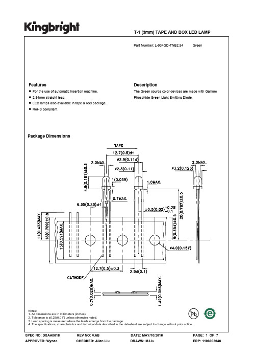
T-1 (3mm) TAPE AND BOX LED LAMP 4. The specifications, characteristics and technical data described in the datasheet are subject to change without prior notice.Selection GuideAbsolute Maximum Ratings at TA=25°CElectrical / Optical Characteristics at TA=25°CPart No.Emitting Color (Material)Lens TypeViewing Angle [1]Min. Typ. 2θ1/2L-934GD-TNB2.54Green (GaP)Green Diffused102540°Iv (mcd) [2] @ 10mASymbolParameterEmitting ColorTyp.Max.UnitsTest Conditionsλpeak Peak Wavelength Green 565 nm I F =10mA λD [1] Dominant Wavelength Green 568 nm I F =10mA Δλ1/2Spectral Line Half-widthGreen30nmI F =10mAC Capacitance Green 15 pF V F =0V;f=1MHz V F [2]Forward VoltageGreen22.5VI F =10mAI R Reverse Current Green 10 uA V R = 5VParameter Values UnitsPower dissipation 62.5 mW DC Forward Current 25 mA Peak Forward Current [1] 140 mA Reverse Voltage5VOperating/Storage Temperature -40°C To +85°C Lead Solder Temperature [2] 260°C For 3 Seconds Lead Solder Temperature [3]260°C For 5 SecondsNotes:1. θ1/2 is the angle from optical centerline where the luminous intensity is 1/2 of the optical peak value.2. Luminous intensity / luminous Flux: +/-15%.3. Luminous intensity value is traceable to CIE127-2007 standards.Notes:1. Wavelength: +/-1nm.2. Forward Voltage: +/-0.1V.3. Wavelength value is traceable to CIE127-2007 standards.4. Excess driving current and / or operating temperature higher than recommended conditions may result in severe light degradation or premature failure.Notes:1. 1/10 Duty Cycle, 0.1ms Pulse Width.2. 2mm below package base.3. 5mm below package base.4. Relative humidity levels maintained between 40% and 60% in production area are recommended to avoid the build-up of static electricity – Ref JEDEC/JESD625-A and JEDEC/J-STD-033.。
dIXEL XR75CX 微型电子温控器 安装使用手册说明书

帝思微型电子温控器(压缩机、融霜、蒸发器风扇、多功能继电器控制)XR75CX请在使用前详细阅读本说明书请将说明书放在温控器附近,以便在需要时能够尽快查阅。
通电前请检查电源电压是否正确。
32 x 74 x60 mm为适用于中/低温强制风冷制冷系统微型温度控制压缩机(制冷输出,也可以控制供液电磁阀)压缩机输出的状态依据探头测得(设定键):在非编程状态下,按一次可显示目标设定点,在编程状态下可用来选择某一参数或确认一个操作。
1592020610AC 防频繁启动延时: (0~50 分钟):从压缩机停机到紧接着的开机需要延时的时,以保护压缩机不出现频繁启动。
间的百分比的值来进行控制调节的百分比,CCt 冷在CCt 的时间内,压缩机一直保持运转不CC CO 探头失灵时压缩机开机运rtr 规定用于控制调节时第一与第二探头所占的百分比(0~100;100=P1,0=P2 ):允许设定一个根据第一、第二探头所占其计算公式为:(rtr(P1-P2)/100 + P2)。
在强冷速冻循环中压缩机持续运行时间: (0.0~24.0小时;分辨率10分钟) 为强速冻循环设定一个压缩机运行时长:停,例如,冷库放满了新的货物时可以使用此功能。
S 强冷速冻循环设定点:(-100~150℃) 为强冷速冻循环设置一个设定点。
n 探头失灵时压缩机开机时间: (0~255分钟):当温度转时间, 当COn=0 、COF ≠0时压缩机总是停机。
COF 探头失灵时压缩机停机时间: (0~255分钟) :当温度探头失灵时压缩机停机时间,当COF=0、COn ≠0时压缩机总是开机。
显示参数CF 。
提示:当修改了测量单位后,请定点(SET )以及Hy 、 LS 、 US 、Ot 、ALU 、ALL 等参数,必要时请修rES Lod 面板显示选择: (P1、P2、P3、P4、SET 、dtr) P1= 库温探头; P2= 蒸发器;rEd P2= 蒸dLy 根据第一、第二探头的百分比来计算得到的融霜 测量单位: (℃/℉) ℃ =摄氏度; ℉ =华氏度检查设改。
Universal-XR 控制器说明书

1.GENERAL DESCRIPTIONModel Universal-XR is a 71x29 mm format microprocessor based controller, it is available in 12/24Vac/dc, 120Vac or 230Vac,and is suitable for applications on high, medium or low temperature refrigeration units. It is provided with three relay outputs to control compressor, defrost - which can be both electrical or hot gas - and evaporator fans. It can work with PTC or NTC probes. Where defrost is being terminated by time, it can operate with just one thermostat probe. Where defrost is being terminated by temperature, it has an input for an evaporator probe(s).The Universal-XR is equipped with a flashing visual alarm and buzzer.Each instrument is fully configurable through special parameters that can be easily programmed through the keypad.2.QUICK START UP PROCEDURE – Up and running in 5 easy stepsThis Quick Start Up section is designed to get you up and running with the minimum of fuss. Just follow these 5 simple steps.+Notes:1.All probes must be of the same type, either PTC or NTC.2.Probes must be at between --58 to 140°F for auto recognition to work;3.If 1 minute expires before you have completed quick set up, either cycle the power OFF then ON to start the set up again orenter Pr2 as per the instructions and adjust your parameter settings manually (see Section 9).Table 1: parameter “tC” settings3.TYPICAL CONNECTIONS - FOR GENERAL GUIDANCE ONLY12/24Vac/dc use Terminals 4 & 5 for power supply 12/24Vac/dc use Terminals 4 & 5 for power supplyTC=3 Cooling, Off Cycle Defrost, Temperature Ended 12/24Vac/dc use Terminals 4 & 5 for power supply TC=4 Cooling, Off Cycle Defrost, Temperature Ended, Alarm Relay 12/24Vac/dc use Terminals 4 & 5 for power supplyTC=5Cooling, Electric or Hot Gas Defrost Temperature Ended 12/24Vac/dc use Terminals 4 & 5 for power supply TC6= Low Temp, Elec. Or Hot Gas Defrost, Temp. Ended, FanControl12/24Vac/dc use Terminals 4 & 5 for power supplyTC7= Open Map to be Configured for any application 12/24Vac/dc use Terminals 4 & 5 for power supply Actual Label on The Control in the Box.Load1 is always Comp, or Heat.Load2 is OAA and Load3 is OAb.4.IMPORTANT: Always set parameter “tC” first. As you move “tC” between settings 1 to 7, all non-relevant parameters will be masked. After settingCompressor off with low temperature alarmREAD ON IF YOU NEED MORE DETAIL6.To enter programming level Pr1 (user programming level), keep both SET and DOWN buttons pressed for 3 sec. The first parameter label will appear. Browse parameter list by using the UP or DOWN keys. Press SET to see a parameter’s current value and UP or DOWN keys to alter its value. Press SET to confirm change (the display will blink for 3 sec and then the next parameter will appear) or by waiting for the menu timeout to expire (15 sec). If no parameter is available for changes in Pr1 level, a noP label will be show.First enter Pr1 level (as described above) then with any parameter label displayed keep both SET and DOWN buttons pressed for 8 sec.The first parameter label will appear. Browse parameter list by using the UP or DOWN keys. Press SET to see a parameter’s current value and UP or DOWN keys to alter its value. Press SET to confirm change (the display will blink for 3 sec and then the next parameter will appear) or by waiting for the menu timeout to expire (15 sec).From Pr2 level it is also possible to add or remove any parameter to / from Pr1 by pressing both SET & DOWN while its label is displayed. Accessibility of any particular parameter via Pr1 level is confirmed by the alarm LED lighting up while its label is displayedWARNING: if no button is pressed for 15 sec, any modified value will be stored into memory and the controller will return to the normal display mode.8.OTHER FEATURES OF THE UNIVERSAL-XRAs well as the main digital display, there are some small icons on the frontpanel. These are used to indicate the status of the loads controlled by theinstrument. Each icon function is described in the following table.For rapid chilling or freezing, the thermostat can be overridden by pressing the UP button until the icon lights up. The compressor will run in continuous mode, for the time period set in parameter CCt. Normal operation will then resume automatically after the CCt is exhausted or when the CCS is exhausted (Continuous Cycle Set Point). The cycle can also be terminated manually by pressing the UP button again for about 3 seconds. 10.DEFROST TYPES-tdF = 0: defrost is electrical;-tdF = 1: defrost is by hot gas.11.EVAPORATOR FAN CONTROL (only when parameter tC = 6 or 7)With [oAb = db], the compressor relay controls cooling as normal but the 3rd (auxiliary/ fan) relay is used to control a heater. The value entered in parameter HY will now be set equal on both sides of the SET POINT. Example: if [HY = 1°C] that will create a 2°C Dead Band.At [SET POINT + HY], cooling switches on. At [SET POINT – HY], heating switches on. Either cooling or heating switch off when temperature returns to SET POINT.The alar m buzzer can be muted, by pressing any button. The controller will briefly show the reset “rES” label. Parameter tbA defines how the alarm relay will respond to the muting of the buzzer.-tbA = n: the alarm relay will remain active until the alarm condition is rectified;-tbA = Y: the alarm relay de-activates when the buzzer is muted.In either case, the display will flash an alarm label until the condition is rectified.The Dixell Universal-XR is provided with an internal watchdog verifying data and memory integrity. Alarm “EE” will flash after detecting a failure in data or in the internal memory. In this case, the alarm output is enabled.WHAT TO DO1.Cancel the alarm by pressing a key.2.Check the value of all parameters and restore correct values when wrong.3.Check the correct instrument operation and in case of further errors replace it.Probe alarms “P1”, “P2” and “P3” start 30 seconds after a fault in probe is detected; they automatically stop 30 seconds after the probe restarts n ormal operation. Check connections before replacing the probe.Temperature alarms “HA” and “LA” automatically stop as soon as the thermostat temperature returns to normal values and when defrost starts. Temperature alar ms “HA2” and “LA2” automatically stop as soon as the condenser temperature returns to normal values.14.REMOVING SECURITY LEVEL PROTECTIONIt is possible to allow access to any parameter from Pr1 level. To do this, go into Pr2 as previously described. Scroll to the label of the parameter you require and then press the SET and DOWN buttons in quick succession. The decimal point LED will be on indicating that access to this particular parameter is now possible from Pr1 level. Its label will now appear when in Pr1 programming level and its value can be altered. To restore security level protection, use the same procedure (the decimal point LED will go out after pressing both buttons).15.MOUNTINGThe Universal-XR should be mounted in a panel, in a 29mm (1.14”) x 71mm (2.8”) hole, and fixed using the special brackets supplied. Ambient temperature for correct operation is 32 to 140°F. Avoid places subject to strong vibrations, corrosive gases, excessive dirt or humidity (20 to 85% non-condensing RH is the recommended working range). Make sure air can freely circulate through the cooling holes slots at the rear side of the controller.16.ELECTRICAL CONNECTIONSThe instrument is provided with screw terminal block to connect cables with a cross section up to 2.5 mm2. Before connecting cables make sure the power supply complies with the instrument’s requirements. Separate the probe cables from the power supply cables, from the outputs and from the power connections. Do not exceed the maximum current rating for each relay; in case of heavier loads use a suitable external relay.It is recommended to place the thermostat probe away from rapid air streams to correctly measure the average room temperature. Place the defrost termination probe among the evaporator fins in the coldest place, where most ice is formed, far from heaters or from the warmest place during defrost, to prevent premature defrost termination.18.Housing: Self-extinguishing ABSSize: Frontal 32x74 mm; depth 70mmMounting: Panel mounting in a 71x29 mm panel cut-outFrontal protection: IP65Connections: Screw terminal block ≤ 2.5 mm2 wiringPower supply: 120Vac, -10% +15% or 230Vac, -10% +15%Power absorption: 4 VA maxDisplay: 3 digits, red LED, 14.2mm highInputs: a maximum of 3 temperature probes, PTC or NTC type.Probes (supplied): 2 x NTC, range-50 TO 110°C (-58 to 230°F) with 1.5 meter (4.98’) cablesRelay outputs: Amps ResistiveCompressor:SPST relay 16FLA / 96LRA, 250VacDefrost: SPDT relay 10A, 250VacFans: SPST relay 5A, 250VacOther output:Buzzer for acoustic signalling of alarmsData storing: Non-volatile memory (EEPROM)Ambient temperature: 0 to 60°C (32 to 140°F)Ambient humidity:20 to 85% (non condensing)Storage temperature: -30 to 85°C (-22 to 185°F)Operating range: PTC: -50 to 150°C (-58 to 302°F); NTC: -50 to 110°C (-40 to 230°F)Resolution: 0.1°C or 1°F (selectable)Accuracy at 25°C: (range -40 to 50°C) ±0.5 °C ±1 digit19.20.CHANGE OVER FROM F TO C OR VIS-VERSA1.Hold the Set & Down (n) buttons, until HY is displayed, release both buttons then hold the Set and Down (n) buttons until Pr2 is displayed. Release the buttons.2.Scroll with the up button to CF, then press and release Set. Change the 1 to 0, then press and release Set.3.Scroll down and adjust the ALL, ALU, FST, AFH, ALH, LS, US, rES as well as the HY.4.Let the control time out to the temp display.Adjust the Set temp by holding the Set until the C or F starts to flash, adjust the set point.21.ENTER YOUR SETTINGS HERE FOR FUTURE REFERENCE (tC=7 SET UP AS DEAD BAND CONTROL)NOTES:__________________________________________________________________________________________________ __________________________________________________________________________________________________ __________________________________________________________________________________________________ __________________________________________________________________________________________________ __________________________________________________________________________________________________ __________________________________________________________________________________________________ __________________________________________________________________________________________________ __________________________________________________________________________________________________ __________________________________________________________________________________________________ __________________________________________________________________________________________________。
dIXEL XR30CX微型温控器(停机融霜、多功能继电器输出)安装使用手册说明书
安装使用手册帝思微型电子温控器(停机融霜、多功能继电器输出)XR30CX请在使用前详细阅读本说明书请将说明书放在温控器附近,以便在需要时能够尽快查阅。
通电前请检查电源电压是否正确。
为适用于中温停机融霜制冷系统的微型温度控制器,压缩机(制冷输出,也可以控制供液电磁阀)压缩机输出的状态依据探头测得面板的键盘操作(设定键):在非编程状态下,按一次可显示目标设定点,在编程状态下可用来选择某一参数或确认一个操作。
15920200306.2如何修改设定值1.持续按下SET 键 2秒钟;2.设定值将被显示出来,并且 “°C” 或 “°F” LED图标指示灯开始闪烁;3.在10秒钟内,通过按或键来修改设定值。
4.要存储新的设定值可再按一次SET 键或者等待10秒钟。
6.3如何启动一次手动融霜持续按下键超过 2秒钟,就可以启动一次手动融霜。
6.4如何修改参数值(进入用户层,第一层)修改参数值的操作如下:1.持续按下SET+ 键超过3秒钟进入编程状态 (“°C” 或“°F”LED图标闪烁)。
2.按或键选择需要的参数,再按 “SET”键来显示参数值。
3.用或键来修改参数值。
4.再按 “SET”键来确认并存储新值,紧接着会显示下一个参数名称。
退出:按下并立即放开SET+ 组和键或不按任何键等待15秒。
注意:不按任何键等待15秒退出时,新值也会被存储。
6.5隐藏参数(第二层)进入隐藏参数层可以浏览到温控器的所有参数。
6.5.1 如何进入隐藏参数层1.首先持续按下SET+ 组合键超过3秒进入(第一层)编程状态 (“℃” 或“°F”LED图标灯闪烁)。
2.释放上述组合键,然后再持续按下SET+ 键超过7秒钟,Pr2字符会一闪而过,紧接着Hy参数会显示出来。
此时您已经进入隐藏参数层。
3.按或键选择需要的参数。
4.按 “SET” 键显示其参数值。
5.用或键来改变其值。
6.再按 “SET”键存储新值,紧接着会显示下一个参数名称。
XEV02D 数码压缩机 PWM 阀门驱动器 用户手册说明书
XEV02DDIGITAL™ 数码压缩机PWM阀门驱动器1.注意事项 (1)2.概述 (1)3.接线 (1)4.报警功能 (1)5.操作面板 (2)6.用户界面 (2)7.参数列表 (2)8.数字输入 (3)9.电气接线 (3)10.RS485 串口线 (3)11.使用编程钥匙 (3)12.报警菜单 (3)13.报警信息 (3)14.技术数据 (3)15.参数表及出厂默认值 (3)1. 注意事项1.1使用此手册前请阅读以下事项•此手册作为产品的一部分应放在驱动器附近,以便快速查阅。
•此驱动器不得作以下说明以外的其他用途,不得作安全保护设备使用。
•请在使用驱动器前检查应用限定范围。
•DIXELL公司有权改变其产品的设计或组成部分,如有改变,恕不另行通知。
1.2安全措施•通电连接前核实供电电压是否正确•不要在有水或潮湿的环境中使用:防止因大气湿度过高引起温度骤变而导致结露。
•注意:进行维修前切断所有的电气连接。
•将探头固定在使用者不易碰到的地方,请勿擅自打开驱动器。
•一旦驱动器出现故障或不能正常控制,可将驱动器详细故障写清楚,并送回到代理商处或Dixell总部(联系方式见本说明书结尾处)•请注意每一个输出继电器输出的最大允许电流(参见技术数据)•请确保探头电缆与负载电缆、电源电缆分开,并保持足够的距离,不要交叉或缠绕。
•驱动器在工业环境使用时,请在驱动器电源输入端并联电源滤燥器(我们的型号:FT1)。
2. 概述该XEV02D作为一个从模块设计与主控制器(如并联机组控制iProRACK)共同使用。
它作为一个纯传感器型控制器,该驱动器从主控制器接收到允许调节输出指令(由数字输入量来实现)和容量控制调节信号(4-20mA或0-10V)控制数码压缩机PWM脉冲卸载阀。
该XEV02D模块配备有一个温度探头输入(可以是一个NTC86K或NTC/PT1000类型)。
一个数字输出(继电器),可用于报警或压缩机输出;一个开路集电极输出,其可以被用作报警输出,一个PWM脉宽调节输出(可控硅类型)来驱动PWM脉冲卸载器阀。
Delphi 电子控制器产品说明书
Kits and Accessories
Part No. Description
A 133504-1 SEAL KIT (includes O-Rings: #14, #4, #3 & #2)
B 133503-1 B 133503-05
SHAFT SEAL KIT (includes Shaft Seal [906006-35], Retaining Ring #15, & Spacer Washer #8)
Description
Req’d.
Poppet Assembly Kit .................................................. 1
Hose Assembly........................................................... 1
Screw, Socket Head, 5/16 -18 x 7/8"......................... 4
Screw, Ground, Binding Head, #10-32 x 3/8”............ 4
Screw, Tapping, #8-32 x ½" ....................................... 2
O-Ring, Switch Coverplate......................................... 2
Cover, Switch ............................................................. 1 Cover .......................................................................... 1 Screw, Hex Head, ¼”-20 x 7/8" ................................. 8 Screw, Hex Head, ¼”-20 x ½".................................... 2
德力西E系列说明书
- 1、下载文档前请自行甄别文档内容的完整性,平台不提供额外的编辑、内容补充、找答案等附加服务。
- 2、"仅部分预览"的文档,不可在线预览部分如存在完整性等问题,可反馈申请退款(可完整预览的文档不适用该条件!)。
- 3、如文档侵犯您的权益,请联系客服反馈,我们会尽快为您处理(人工客服工作时间:9:00-18:30)。
SET +
返回到库温显示。
4.1 指示灯
每个指示灯的功能如下表所示:
指示灯
状态 亮
闪烁 亮
闪烁
亮 闪烁
功能
压缩机工作
-参数设置阶段 (与 -抗短路延时动作 融霜工作
同时闪烁)
- 参数设置阶段 (与 同时闪烁) - 排水时间 风扇工作 (不适用于 XR10-20)
融霜后风扇延时 (不适用于 XR10-20)
重新恢复正常控制的时间间隔。这段时间蒸发器排出融霜产生的滴水
风扇
FnC 风扇运行模式(仅适用于 XR60C): C-n= 风扇与压缩机同启同停,融霜时停止; o-n =风扇持续工作, 融霜期停止; C-Y =与压缩机同时工作, 融霜期启动; o-Y = 风扇持续工作,融霜期启动。
Fnd 融霜后风扇延时动作(仅适用于 XR60C):(0~255 分) 融霜结束至蒸发 器风扇启动间的时间间隔。
2. 选择所需参数; 3. 按下“SET”键显示其值( 指示灯闪烁); 4. 按 或 修改该值; 5. 按“SET”键存储新值,并进入到下列参数。 退出:按 SET+ 或不按任意键等待 15 秒退出。 注意:即使等待时间终止,程序退出,新设定的参数也将被保存。
4.9 隐藏菜单(第二层) 隐藏菜单包含控制器全部参数
• LS 最小设定值 (- 50°C~SET): 设定温度下限值。 • US 最大设定值(SET~ 150°C). 设定温度上限值。
Ot 温控器探头校准值:(-12.0~+12.0℃)能够调节温控器探头温差补偿。 P2P 当前蒸发器探头(不适用于 XR10-20): n= 当前无: 融霜按时间停止
y= 当前有,融霜按温度停止。 • OE 蒸发器探头校准值(不适用于 XR10-20): (-12.0~12.0°C).能够调节
Dixell使用手册小精灵多功能电子温控器
XR10C/XR20C/XR40C/XR60C
E 系列
目录: 1. 注意事项________________________________1 2. 概述 ____________________________________1 3. 控制负载________________________________1 4. 键盘 ____________________________________1 5. 参数 ____________________________________2 6. 安装固定方法 ___________________________3 7. 电气连接________________________________3 8. 报警信号________________________________3 9. 技术参数________________________________3 10. 电路连接图______________________________3 11. 缺省设定值______________________________3
设定蒸发器探头探测的融霜终止温度 。 IdF 融霜周期间隔: (0÷120 小时) 设定两次融霜周期开始的时间间隔 MdF (最大)融霜时间: (0~255 分) 当 P2P = n, (无蒸发器探头:时间融霜)
设置融霜持续时间,当 P2P = y (据温度结束融霜)设置融霜最大时间 。 • dSd 启动融霜延时(不适用于 XR10-20): ( 0÷99 分) 为避免过载启动设
4.2 查看温度下限 1. 按下并立即释放 下调键。 2. 参数“Lo”出现后,显示最低温度。 3. 按下并立即释放下调键或等待 5 秒恢复探头值显示。
4.3 查看温度上限 1. 按下并立即释放上调键。 2. 参数“Hi”出现后,显示最高温度。 3. 按下并立即释放上调键或等待 5 秒恢复探头值显示。
XR10C - XR20C – XR40C – XR60C
1/4
Dixell
使用手册
3. 按 或 在 15 秒内更改参数值; 4. 再次按“SET”键或等待 15 秒存储新参数值。
4.7 启动手动融霜 按下“DEF”键持续 2 秒以上,启动手动融霜。
4.8 更改参数值
更改参数值操作如下:
1. 按下 SET+ 持续 3 秒,进入参数调节状态( 和 同时开始闪烁);
起温度骤变而导致冻结。 z 注意:进行维修前切断所有的电气连接。 z 将探测头远离终端用户,勿擅自打开设备。 z 设备运行失败出现故障,可将设备详细故障写清楚,并送交到
代理商处或 DIXELL 意大利帝思中国代表处。 z 选择每个继电器的最大允许电流 (参照技术数据) 。 z 将探头电缆,负荷和电源电缆分开,并保持适当间距,不要交
4.9.1 进入隐藏菜单
1.按下 SET+ 3 秒,进入参数调节状态
( 和 开始闪烁);
2.显示参数时,按下 SET+ 刻在 HY 参数后显示; 现在你进入了隐藏菜单
7 秒以上,“Pr2”字符立
3.选择所需参数; 4.按“SET”键显示其值( 闪烁);
5.按 或 更改其值; 6.按“SET”键存储新值,并进入下列参数。
3.4 蒸发器风扇控制 通过“FnC”参数选择风扇控制模式: FnC = C_n 风扇与压缩机同起同停,融霜期停止工作; FnC = o_n 压缩机停止,风扇工作,融霜期停止工作;由“Fnd”参数设置
融霜后,蒸发器排水时间。 FnC = C_Y 风扇与压缩机同起同停,融霜期工作; FnC = o_Y 融霜期风扇继续工作。 附加“FSt”参数为风扇停止温度,蒸发器探头探测温度高于“FSt”值,风扇停 止,只有温度低于“FSt”值时,才能启动风扇,确保空气流通。
• ALd 温度报警延时:(0~255 分) 从检测到报警至发出报警间时间间隔。 • dAO 启动时忽略温度报警: (从 0.0 分 到 23.5 小时) 设备启动后,从检
测到报警至发出报警的时间间隔。
其它
• dP2 显示第二支探头值(不适用于 XR10-20) • rEL 内部使用软件版本 • Ptb 参数代码:只读
FSt 风扇停止的温度(仅适用于 XR60C)::(-50~50°C) 设定风扇停止温度, 蒸发器探头探测温度高于该值时,风扇关闭。
报警
ALU 温度上限报警: (ALC=Ab: ALL÷150°C; ALC=rE 0÷50°C) 当温度达到上限 值,“ALd”延时后,报警动作 。
ALL 温度下限报警: (ALC=Ab -50.0°C÷ALU; ALC=rE 0÷50°C) 当温度达到下限 值,“ALd”延时后,报警动作 。
退出:按 SET+ 或不按任意键等待 15 秒退出。 注意:即使等待时间终止,程序退出,新设定的参数也将被保存。
4.9.2 将隐藏菜单的参数放入第一层及将第一层参数放入隐藏菜单
隐藏菜单中当前每一个参数均可被删除或按 SET+ 键放入 第一层(用户层)。 在隐藏菜单中,位于第一层的参数小数点亮。
4.10 锁键盘
1. 注意事项
3.3 融霜 XR40C-E,XR60C-E 通过设定“tdF”参数,可选定两种融霜方式,即电热(tdF = EL)和热汽(tdF = in) 融霜。其它参数可用于控制融霜周期间隔(IdF),融霜最大周期(MdF)及两种融 霜方式:通过蒸发器探头(P2P)控制或调节时间。融霜停止时,启动排水, 时间由 FST 参数设定。FST=0 时,停止排水。
定的融霜时间。 • dFd 融霜期温度显示: (rt =实际温度; it = 启动融霜时的温度; SEt =
设定值; dEF = “dEF” 字符) • dAd 融霜结束后显示延时: (0~255 分).设定融霜结束至恢复显示库温
值间的最大时间 。 • Fdt 排水时间(不适用于 XR10-20): (0∼120 分) 达到融霜终止温度至
蒸发器探头温差补偿 。 • OdS 启动时输出延时: (0~255 分)该功能在设备首次启动及参数设定
时禁止任何输出时有效。 AC 抗短路延时:(0~50 分)压缩机停止及重新启动的时间间隔。 • COn 探头失灵时压缩机运行时间:(0~255 分) 探头失灵后,压缩机工
作时间。COn=0 时压缩机处于关机状态。 • COF 探头失灵时压缩机停止时间: (0~255 分) 探头失灵后压缩机停止工
叉或缠绕。 z 当设备应用于工业环境时,过滤器应与电感负荷并联使用。
2. 概述
XR10C 其尺寸规格为 32×74 ㎜,用于制冷或加热领域里单级温度控制。一 路继电器输出控制压缩机工作,一支 NTC 探头输入。特殊参数可全部通过 键盘方便地设置。 XR20C 是用于常温制冷的停机化霜型温控器。其尺寸规格为 32×74 ㎜。一 路继电器输出控制压缩机工作,一支 PTC 或 NTC 探头输入。内置时钟控制 化霜周期。特殊参数可全部通过键盘方便地设置。 XR40C 是 适 用 于 中 低 温 制 冷 系 统 的 微 电 脑 控 制 器 。 其 尺 寸 规 格 为 32x74mm。 两路继电器输出控制压缩机及电气或热汽除霜。两支 PTC 或 NTC 传感器输入,用于控制温度及融霜停止温度。可通过键盘编程,设定 参数。 XR60C 是适用于中、低温通风型制冷系统的微型控制器。其外形尺寸为 32x74 mm 。三路继电器输出控制压缩机、蒸发器及电气或热汽融霜。两支 传感器 NTC 输入,一支用于测量温度,另一支装在蒸发器上,用于测量融 霜终止温度并控制蒸发器工作。
4. 键盘
1.1 使用此手册前请阅读以下事项
z 此手册作为产品的一部分应放在设备附近,以便快速查阅。 z 此设备不得作以下说明以外的其他用途,不得作安全保护设备
使用。 z 投入运行前检查应用量程。
1.2 安全措施
z 进行设备连接之前,检查供电电源是否正确。 z 不要将仪器置于水中或潮湿的环境中,防止因大气温度过高引