JEL 801 2010_Japan_T8
Product_Overview_by_Linglin
Target voltage 1.8 .. 3.6 V 600 MHz effective sample rate Supports Embedded Trace
Macrocell (ETM)
Supports Program Trace Macrocell
(PTM)
Support of High-Speed Serial Trace Port Compatible to Xilinx Aurora protocol Support of up to four differential lanes Maximum 6,25Gbit/s lane speed Up to 24 Giga CPU cycles
Support for ARM/CORTEX, PIC32, X-GOLD110, X-GOLD102 ACTEL, ARM, ATMEL, CYPRESS, ENERGYMICRO, FREESCALE, FUJITSU, INFINEON, LUMINARYMICRO, MICROCHIP, MIPS, NXP, SAMSUNG, STM, TI, TOSHIBA
Export Form 2011▪ Linglin He ▪ 2011/ August / 18
▪ 5
Products
Power Debugger
Debug Cable
Processor specific adaption Contains software license Supported Processor Families: ARM/XSCALE Power Architecture MIPS32/MIPS64 Intel Atom™/x86 78K0R/RL78 APS AVR32 C166CBC CPU32 ColdFire H8S/23x9 M32R M-Core MCS08 MSP430 RX S12X SH TriCore V850 VR XC2000/C166SV2 XC800 DSPs Softcores Configurable Cores Auxiliary Processors
JEL801(2010)

【直管形LEDランプと直管形LEDランプ専用照明器具のイメージ】2社団法人日本電球工業会の「L形口金付直管形LEDランプシステム」に関する規格について(JEL801:2010「L形口金付直管形LEDランプシステム(一般照明用)」から抜粋)(1)概要~略~当工業会としては、このような既設の蛍光灯照明器具にそのまま交換できる直管形のLEDランプ類が市場で問題となっていたため、さまざまな方法で、注意喚起を行ってきました。
また、経済産業省からは、業界を主導する立場として、早急に、安全が確認できるものから、先行的に標準化を進めていくべきであるなどのご指導を受けておりました。
このような状況の中、早急に、市場の課題を把握するとともに、それらの課題(互換性・落下・フリッカなど)を解決するためのシステムとして、適切な標準化(規格)を示すことが、当工業会としての非常に重要な責務であると考え、このJELを発行することとなりました。
序文11.適用範囲12.引用規格13.用語及び定義24.ランプの要求事項45.ランプの安全性要求事項56.ランプの性能要求事項107.ランプの形式118.ランプの表示119.制御装置の要求事項1410ソケットの要求事項15附属書A(規定)口金表面の温度上昇試験18附属書B(規定)ランプの電気的特性及び光学的特性の試験方法19附属書C(規定)ランプの光束維持率及び寿命試験の点灯条件20附属書D(参考)ランプの形式21附属書E(規定)ソケットのリスト2211データシート2311.1ランプデータシートNo.の一般法則2311.2ランプ寸法測定位置の図示データシート2311.3ランプデータシート23≪ご参考≫社団法人日本電球工業会HP http://www.jelma.or.jp/以上(2)目次(3)規格の詳細。
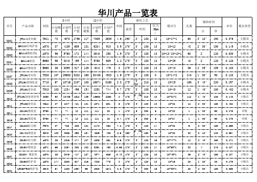
华川产品一览表
QD1115胶套
E660 96 3840 459 144 5760 689 2.2 175° 3′ 180 13
10-29
QD1117橡胶垫 E660 86 3095 317 129 4642 476
3 175° 3′ 180 13
10-43
JFZ191密封垫 T520 107 25600 3282 160 38400 4923 1.6 175° 3′ 180 0
E790
152
1364 187
227
2046
280
3.6 175° 2′ 120 13
10-11
9
8036
“□”67.8×63.5 ×2.3
E790
220
1979 271
330
2968
406
3.6 175° 2′ 120 13
10-10
9
8037 5×2
O形圈 F751 192 12288 525 288 18432 788 0.21 190° 2′ 120 13
大模具 小模具 小模具 小模具 小模具 大模具 小模具 小模具 大模具 小模具
单模 单模 小模具 小模具 小模具 小模具 小模具 小模具 小模具
8033
110J橡胶插头 G540 87 3142 255 131 4713 383 0.6 175° 3′7.8×64.5 ×2.3
1′30″ 90
1′30″ 90
2′30″ 150
2′10″ 130
2′40″ 160
4′
240
2′40″ 160
1′20″ 80
2′30″ 150
单价 模具类型
0.376 0.145 0.030 0.120 0.103 0.128 0.197 0.402 0.145 0.402 0.179 0.179 0.299 0.094 0.171 0.137 0.137 0.179 0.855
SDS-C-809CN U-BOND ST-10HA Hardener

9.物理和化学性质
外观(物理状态,形状): 浆糊 颜色: 淡黄色~透明淡褐色 气味: 硫醇气味 pH值: 无关
熔点/凝固点: 无数据 沸点,开始蒸发温度
和沸腾范围: 无数据 闪点: > 122℃ (Cleveland Open Cup)
自燃温度(着火点): 无数据 燃烧性(固体,气体): 无关
燃烧或爆炸范围的 上限/下限: 无数据 蒸汽压: 无数据 蒸汽密度: 无数据 蒸发速度: 无数据
苯酚诱导体
可能导致皮肤过敏反应
分类1
间苯二甲胺(MXDA)
分类1
苯酚诱导体
特定目标器官系统毒性(单次接触)
分类1
对器官造成损害
分类1
间苯二甲胺(MXDA)
特定目标器官系统毒性(重复接触)
分类1
长时间或重复接触对器官造成损害
分类1
苯酚诱导体
12.环境影响信息
小白鼠LD50 660-980mg/L 小白鼠LD50 4000mg/kg 小白鼠LD50 2600mg/L
4.应急措施
吸入时: 包括和主剂的混合物中的蒸汽。如误吸入温度上升时所产生的蒸汽,引起发痒等异常症状,立即将受 害者转移到空气新鲜处,迅速求医治疗。
接触皮肤时: 立刻抹掉,用肥皂水充分清洗。不能用溶剂,乙酸异戊酯(香蕉水/天那水)。如出现发痒症状,迅速 求医治疗。
进入眼睛时: 立即用大量水冲洗。如不能除去,引起发痒等异常症状,迅速求眼科医生治疗。 吞入时: 立即用水充分漱口。饮入水分或牛乳。如可能使其呕吐,不要诱导呕吐。迅速求医治疗。如果受害 者没有意识,不得吃东西,喝水等饮食物。
对环境的有害性: 对水生环境的有害性(急性) 对水生环境的有害性(慢性)
<上述未记载的危险有害性,区分外,分类对象外。>
Tait T800 Series II 电子产品说明书

Radio Systems Division, Tait Electronics LtdPage 1 of 16535 Wairakei Rd, P .O. Box 1645, Christchurch, New Zealand Phone: (64) (3) 358 3399 Fax: (64) (3) 358 2825Application Note AN-RSD-002Combining Third Party Equipment With The T800 Series II Radio Platform23 April 1998T800Any enquiries regarding this Application Note should be addressed in the first instance to your nearest approved Tait Dealer or Subsidiary . Further assistance may be obtained from the Cus-tomer Support Group, Radio Systems Division, Tait Electronics Ltd, Christchurch, New Zealand.IntroductionThis Application Note provides guidelines on combining third party equipment with the Tait T800 Series II radio platform. It shows pin inputs and outputs available on T800module and backplane D-range connectors and provides information on integrating third party equipment into a Tait rack frame, using the T800 ancillary chassis and rack frame guides.Third party equipment can be combined with Tait T800 Series II equipment in the fol-lowing ways.•You can interface equipment to T800 radio units via the D-range on individual modules (T800 receiver, transmitter/exciter, power supply), or via the back-plane PCB which interconnects the modules at the rear of the T800 rack frame.•You can integrate third party PCBs into a T800 rack frame by using a T800ancillary module chassis.This document is split into three main sections.•T800 Series II EquipmentGives guidelines for combining the Tait T800 Series II radio platform with third party equipment. It describes the standard Tait rack frame, the T800 radio mod-ules and location of the D-range on the modules and the backplane PCB (which is fitted to the rear of the rack frame).•T800 Series II Module Inputs And OutputsGives pin inputs and outputs for interfacing third party equipment with the T800 receiver, transmitter/exciter and power amplifier (PA), and the modules matching pin inputs and outputs on the backplane PCB.•Integrating Third Party PCBsGives specific dimensions for integrating third party PCBs into the ancillary chassis, and information on single, double and triple guide kits.AN-RSD-002T800 Series II EquipmentRack FrameThe T800-22-0000 is a standard 5U high, 19” wide base station/repeater rack frame. The rack frame can house the range of T800 Series II modules within the frequency range 66-960MHz, with power outputs ranging from 1-100W. Changing links on the back-plane PCB allows the Tait equipment in the rack frame to be configured as either a base station or a repeater.Figure 1 shows the mechanical layout of the T800-22-0000 rack frame. Modules slide into the rack frame along guides (single, double or triple) and can interface to third party equipment through the backplane PCB.Figure 1 Mechanical Layout Of The T800-22-0000 Rack FramePage 2 of 1623/04/98AN-RSD-002T800 Radio ModulesThird party equipment can be interfaced with the T800 receiver, transmitter/exciter or power amplifier through the 15-way D-range on the rear of the modules. An auxiliaryD-range (normally fitted as D-range 2) can be bought as an additional kit (T800-03-0000)for all modules except the PA. This provides you with additional D-range inputs and outputs. Typical uses of the T800-03-0000 are in paging, multichannel and remote con-trol applications and where external channel control is required.The D-range location on the module is shown in Figure 2. Available pin inputs and out-puts are described for the T800 receiver, transmitter/exciter and power amplifier mod-ules individually later in this document. Modules can be interfaced with the backplane PCB by way of the D-range sockets as shown on Figure 3.Space For OptionalD-range Plug(D-range 2)D-range Plug(D-range 1)Figure 2 D-range Location23/04/98Page 3 of 16AN-RSD-002Backplane PCBThe backplane PCB (T800-50-0000) has been laid out with OEM (Original Equipment Manufacturer) products in mind, and has sockets for the T800 module D-range. The PCB mounts across the rear panel of the rack frame guides, enabling a T800 Series II radio module to plug directly into the D-range sockets provided on the inner side of the PCB.The two 25-way D-ranges (shown enlarged in Figure 3) can be used to interface third party equipment, for example tone remote boards, with the T800-22-0000 rack frame. Most D-range inputs/outputs are made available on the two 25-way D-ranges (SK6 and SK7) and are described in following tables.25-way D-rangeSK725-way D-rangeSK6Figure 3 T800-50-0000 Backplane PCB Showing D-range LocationPage 4 of 1623/04/98AN-RSD-00223/04/98Page 5 of 16T800 Series II Module Inputs And OutputsReceiver : Standard Inputs And OutputsTable 1 shows standard inputs and outputs for the T800 receiver and corresponding inputs and outputs on the backplane PCB (SK7).Table 1 Standard Receiver Pin Inputs & OutputsNotes:DR1 = D-range 1 BKPL = Backplane.SignalDR1 PinBKPL (SK7)I/P O/PFunctionLine O/P1-41-4O/PAudio output from a 600Ω balanced line transformer. Output level adjustable from -50 to +10dBm via a potentiometer on the front panel. Pins 2 & 3 are usually linked for normal operation.RSSI 55O/PReceiver Strength Signal Indicator. Provides a DC voltage propor-tional to the signal strength of the received signal.Values are: VHF 4.5V @ -100dBm; 1V/15dB (-115 to -70dBm) UHF 2V @ -110dBm; 1V/10dB (-115 to -70dBm). For UHF, optional board must be fitted.Audio 166O/PAudio 1 allows access to audio before it passes through the squelch circuitry . The output will provide frequencies down to 5Hz when the audio processor is linked for flat response. From Audio 1, audio can be passed to external CTCSS and signalling decoders.Serial Com/Audio 277I/OSerial programming input for programming the module. Can be configured as Audio 2 by internal link resistors if required. Audio 2 is an input and when used in conjunction with Audio 1 allows the audio path to be broken so that external audio processing can be used.Speaker 819O/P Provides up to 1W into a 4Ω speaker.Supply V oltage 9-10-I/P DC Supply V oltage input. Nominal 13.8V , can operate from 10.8 to 16V DC.Gate O/P1114O/PPulls low when a signal is received. In a repeater, configuration can be used to key the transmitter by directly connecting it to the Tx Key pin.Receiver Gate Relay12131516O/PRelay CommonRelay Normally OpenA normally open relay contact that closes when a signal is received. The relay will only operate when PL270 is linked.Ground 14-15-I/P Power supply earth, negative ground.Backplane SK7123456789101112131415Receiver D-range 1Page 6 of 1623/04/98AN-RSD-002Receiver : Additional Inputs And OutputsTable 2 shows additional inputs and outputs for the T800 receiver and corresponding inputs and outputs on the backplane PCB (SK6).Table 2 Additional Receiver Pin Inputs & OutputsNotes :DR2 = D-range 2 BKPL = BackplaneSignalDR2 PinBKPL (SK6)I/P O/PFunctionChannel 1 22Select 0-6 2 9 3 214 8 I/P5 2067 7 19External channel select pins (including Channel Select 7 on pin 11). Normally high, these pins are pulled low to select logic 0. To select a channel the binary equivalent must be applied to the pins. when all pins are left floating (i.e. high) then the selected channel is deter-mined by software (PGM800Win).Note: When using external channel selection, pin 11 must be pulled low.Ground 86I/P Power supply earth, negative ground.Rx Disable 918I/PWhen pulled low disables receiver audio output. Usually used in a base station application to ensure there is no interference when the transmitter is operating.CTCSS Disable 105I/P Disables CTCSS (Continuous Tone Controlled Squelch System).Channel Select 71123I/P Function as for other channel select lines. Must be pulled low when using external channel selection.Serial Comm1224I/OSerial programming input for programming the module. Can be used if it is not possible to program the radio from D-range 1.Aux-Out 13 150-2 14 10 O/P 15 11Open drain type; capable of sinking 2.25mA via 2k2Ω; V ds max.=5V . Logic state can change when the channel is er definable by using PGM800Win software.Backplane SK6Receiver D-range 2123456789101112131415AN-RSD-00223/04/98Page 7 of 16Transmitter/Exciter : Standard Inputs And OutputsTable 3 shows standard inputs and outputs for the T800 transmitter/exciter and corre-sponding inputs and outputs on the backplane PCB (SK7).Table 3 Standard Transmitter/Exciter Pin Inputs & OutputsNotes :DR1 = D-range 1 BKPL = Backplane.SignalDR1 PinBKPL (SK7)I/P O/PFunctionLine I/P 1-422-25I/PAudio input to a 600Ω balanced line transformer. For an unbalanced line connect the line I/P 4 to ground. Accepts audio levels as low as -30 dBm. Pins 2 & 3 are usually linked for normal operation.Tx Enable 521O/P Pulls low when the transmitter is keyed. Usually connected directly to Tx Key on the PA to activate the PA alarm circuitry .Audio 2620I/PAudio 2 allows audio to be input to the audio processor bypassing the 600Ω line transformer. Ideal place to re-inject audio such as a voice scrambler after external processing.Serial Com/Audio 177I/O O/PSerial programming input for programming the module. Can be configured as Audio 1 by internal link resistors if required. Audio 1 allows access to the audio directly after the 600Ω line transformer. When used in conjunction with Audio 2 it allows the audio path to be broken so that external audio processing can be used.CTCSS 818I/P An external input for CTCSS or DCS (Digital Coded Squelch). Supply V oltage 9-10-I/P DC Supply V oltage input. Nominal 13.8V , can operate from 10.8 to 16V DC.Opto Keys 11 (+)12 (-)98I/PA high isolation keying option. A DC voltage between 6V and 50V applied to these inputs will key the transmitter. The inputs may be used to key the transmitter via a DC remote.Tx Key 1317I/P A high impedance input which is pulled low to key the transmitter. Must be <0.7V or connected directly to Ground.Ground14-15-I/PPower supply earth, negative groundBackplane SK7T ransmitter/Exciter D-range 1123456789101112131415Page 8 of 1623/04/98AN-RSD-002Transmitter/Exciter : Additional Inputs And OutputsTable 4 shows the additional pin inputs and outputs for the T800 transmitter/exciter and corresponding inputs and outputs on the backplane PCB (SK6).Table 4 Additional Transmitter/Exciter Pin Inputs & OutputsNotes :DR2 = D-range 2 BKPL = Backplane.SignalDR2 Pin BKPL (SK6)I/P O/PFunctionChannel 1 22Select 0-6 2 9 3 214 8 I/P5 2067 7 19External channel select pins (including Channel Select 7 on pin 11). Normally high, these pins are pulled low to select logic 0. To select a channel the binary equivalent must be applied to the pins. When all pins are left floating (i.e. high) then the selected channel is deter-mined by software (PGM800Win).Note: When using external channel selection, pin 11 must be pulled low.Ground 86I/P Power supply earth, negative ground.Tx Relay Drive 918I/P Used for coaxial relay switching. Pulls to ground when the transmit-ter is keyed.CTCSS Disable 1017I/P Disables CTCSS (Continuous Tone Controlled Squelch System).Channel Select 71123I/P Function as for other channel select lines. Must be pulled low when using external channel selection.Serial Comm1224I/OSerial programming input for programming the module. Can be used if it is not possible to program the radio from D-range 1.Aux-Out 13 160-2 14 4 O/P 15 3Open drain type; capable of sinking 2.25mA via 2k2Ω; V ds max.=5V . Logic state can change when the channel is er definable by using PGM800Win software.Backplane SK6123456789101112131415T ransmitter/Exciter D-range 2AN-RSD-00223/04/98Page 9 of 16Power Amplifier : Standard Inputs And OutputsThe location of the D-range on the T800 PA is shown on the diagram below. Available pin inputs and outputs for the PA are shown on Table 5.Table 5 Power Amplifier Pin Inputs & OutputsSignal DR1 PinBKPL (SK7)I/P O/PFunctionSupply V oltage1-2-I/P DC Supply V oltage input. Nominal 13.8V , can operate from 10.8V to 16V DC. Connected to pins 9, 10 and 11.Forward Power Alarm 310O/PThese are normally low and float if forward power drops below, or reverse power rises above, pre-set limits. They have a 500mA sink capability . A signal is only provided when the Tx Key line on the PA is being pulled low.Reverse Power Alarm 411O/PForward Power Metering 512O/PV oltage outputs proportional to the levels of forward and reverse power are available at these pins for metering purposes. There is enough output to drive a coil meter.Reverse Power Metering613O/PGround 7-8-I/P Power supply earth, negative ground. Connected to pins 13, 14 and 15.Supply V oltge9-11-I/P Function as for Pins 1 and 2.Tx Key1221I/P Keys the PA when ground is applied. This line is usually taken to the Tx Enable line on the Exciter.Ground13-15-O/PPower supply earth, negative earth.123456789101112131415D-range ConnectorP A D-rangeBackplane SK7Page 10 of 1623/04/98AN-RSD-002Integrating Third Party PCBsThis section gives guidelines on integrating third party PCBs with Tait equipment using the T800 ancillary module chassis and rack frame guides.There are two types of PCB which will fit into the T800 ancillary module chassis, a pri-mary PCB and a front panel PCB.Primary PCBYou can fit the primary PCB into the body of the T800 ancillary module chassis by slid-ing it along one of the grooves (the grooves are shown in the diagram of the chassis,Figure 7). PCBs can be fitted into any of the three grooves in the chassis.Third party PCBs must be made to specific dimensions to ensure they integrate with the T800 ancillary module chassis. The dimensions of the main PCB are shown in Figure 4.All measurements are shown in millimetres.The grey shaded area represents the part of the PCB where components are unplaceable as it is the area at the edge of the PCB covered by the chassis. This is a 3mm wide area.The black area represents the part of the PCB where components should be of a restricted height. The maximum height for components in this area is 3.2mm. The maxi-mum component height for the rest of the PCB area is 42mm. The length of the primary PCB is 260mm, but longer PCBs can be fitted if a front panel PCB is not required.Figure 4 Main PCB DimensionsLocation Of Pin 1 D-range 1Figure 5 shows the footprint and spacing dimensions of the 15-way double D-range connector. The location of pin 1 on both D-range 1 and D-range 2 is also shown. All dimensions are shown in millimetres.Figure 5 D-range Connector DimensionsPin 1 Of D-range 2Pin 1 Of D-range 1∅ 1.1∅ 3.2Front Panel PCBFigure 6 below shows the dimensions necessary for a third party PCB to fit behind the front panel of the ancillary chassis. All measurements are shown in millimetres. The maximum height of components on this PCB is 8mm.The PCB fits in behind the front panel and is screwed to a sub-chassis panel using M3x8 Pan Torx Taptite screws. The T800 ancillary module chassis is shown in Figure 7.Figure 6 Front Panel PCB DimensionsAncillary Module ChassisThe mechanical design of the T800-08-0000 ancillary module chassis is shown in Figure 7. Third party PCBs can be fitted into the chassis, either as a primary PCB (shown in Figure 4) or as a smaller PCB which fits behind the front panel (shown in Figure 6).The primary PCB slides into a groove in the T800 ancillary module chassis and the front panel PCB screws in behind the front panel using the sub-chassis panel (shown in Figure 7).The T800 ancillary module chassis is held in the rack frame by the rack frame guides. The rack frame guides are described on following pages.15-WayDouble D-rangeConnectorPrimary PCB Slides Into GrooveFront Panel PCB Screws InUsing Sub-Chassis PanelFigure 7 T800-08-0000 Ancillary Module ChassisAll parts shown on Figure 7 excluding the PCBs are included in the T800 ancillary mod-ule chassis kit.T800-41-0001 - Single Guide KitThe T800-41-0001 rack frame guide shown in Figure 8 is designed to fit into the T800Series II rack frame (T800-22-0000). The single guide accepts the T800-08-0000 ancillary chassis or a T800 Series II module (except for power supplies and power amplifiers which must use their own guides).The single guide kit is supplied disassembled and comprises a top and bottom rail, a rear panel, two D-range sockets and mounting screws.Figure 8 T800-41-0001 Single GuideRack Mounting HolesAperture For RF ConnectorsSlots For D-range ConnectorsRack Mounting Hole sOptional Backplane PCB Mounts On Rear Of GuideRack Mounting HoleFront Panel Mounting HolesT800-41-0002 - Double Guide KitThe T800-41-0002 rack frame guide shown in Figure 9 is designed to fit into the T800Series II rack frame (T800-22-0000). The double guide accepts any combination of the T800-08-0000 ancillary chassis and T800 Series II modules (except for power supplies and power amplifiers which must use their own guides).The double guide kit is supplied disassembled and comprises two top and bottom rails,a double width rear panel, four D-range sockets and mounting screws.Figure 9 T800-41-0002 Double GuideFront Panel Mounting HolesRack Mounting HolesRack Mounting HolesRack Mounting HolesSlots For D-Range ConnectorsRack Mounting HolesAperture For RF ConnectorsOptional Backplane PCB Mounts On Rear Of GuideT800-41-0003 - Triple Guide KitThe T800-41-0003 rack frame guide shown in Figure 10 is designed to fit into the T800Series II rack frame (T800-22-0000). The triple guide accepts any combination of the T800-08-0000 ancillary chassis and T800 Series II modules (except for power supplies and power amplifiers which must use their own guides).The triple guide kit is supplied disassembled and comprises three top and bottom rails,a triple width rear panel, six D-range sockets and mounting screws.Figure 10 T800-41-0003 Triple GuideFront Panel Mounting HolesRack Mounting HolesRack Mounting HolesOptional Backplane PCB Mounts On Rear Of GuideRack Mounting HolesAperture For RF ConnectorsRack Mounting HolesSlots For D-range Connectors。
9V NEDA 1604(Eveready 216或等效产品)电源替换
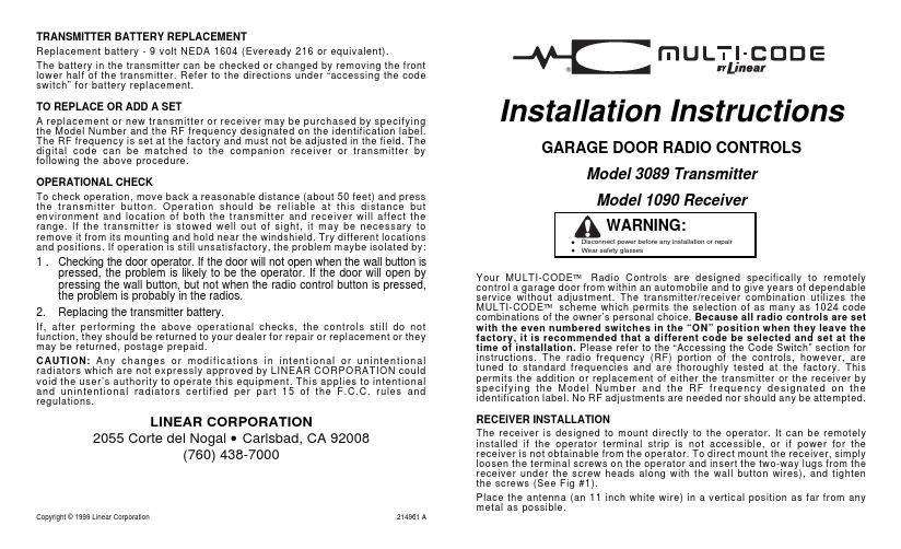
TRANSMITTER BATTERY REPLACEMENTReplacement battery - 9 volt NEDA 1604 (Eveready 216 or equivalent).The battery in the transmitter can be checked or changed by removing the front lower half of the transmitter. Refer to the directions under “accessing the code switch” for battery replacement.TO REPLACE OR ADD A SETA replacement or new transmitter or receiver may be purchased by specifying the Model Number and the RF frequency designated on the identification label. The RF frequency is set at the factory and must not be adjusted in the field. The digital code can be matched to the companion receiver or transmitter by following the above procedure.OPERATIONAL CHECKTo check operation, move back a reasonable distance (about 50 feet) and press the transmitter button. Operation should be reliable at this distance but environment and location of both the transmitter and receiver will affect the range. If the transmitter is stowed well out of sight, it may be necessary to remove it from its mounting and hold near the windshield. Try different locations and positions. If operation is still unsatisfactory, the problem maybe isolated by: 1 .Checking the door operator. If the door will not open when the wall button ispressed, the problem is likely to be the operator. If the door will open by pressing the wall button, but not when the radio control button is pressed, the problem is probably in the radios.2.Replacing the transmitter battery.If, after performing the above operational checks, the controls still do not function, they should be returned to your dealer for repair or replacement or they may be returned, postage prepaid.CAUTION: Any c hanges or m odifications in intentional or unintentional radiators which are not expressly approved by LINEAR CORPORATION could void the user’s authority to operate this equipment. This applies to intentional and unintentional radiators certified per part 15 of the F.C.C. rules and regulations.LINEAR CORPORATION2055 Corte del Nogal • Carlsbad, CA 92008(760) 438-7000Copyright © 1999 Linear Corporation214961 AInstallation Instructions GARAGE DOOR RADIO CONTROLSModel 3089 TransmitterModel 1090 ReceiverWARNING:•Disconnect power before any installation or repair•Wear safety glassesYour MULTI-CODE™ Radio Controls are designed specifically to remotely control a garage door from within an automobile and to give years of dependable service without adjustment. The transmitter/receiver combination utilizes the MULTI-CODE™ scheme which permits the selection of as many as 1024 code combinations of the owner’s personal choice. Because all radio controls are set with the even numbered switches in the “ON” position when they leave the factory, it is recommended that a different code be selected and set at the time of installation. Please refer to the “Accessing the Code Switch” section for instructions. The radio frequency (RF) portion of the controls, however, are tuned to standard frequencies and are thoroughly tested at the factory. This permits the addition or replacement of either the transmitter or the receiver by spec if ying the M odel N um ber and the R F frequency designated on the identification label. No RF adjustments are needed nor should any be attempted.RECEIVER INSTALLATIONThe receiver is designed to mount directly to the operator. It can be remotely installed if the operator terminal strip is not accessible, or if power for the receiver is not obtainable from the operator. To direct mount the receiver, simply loosen the terminal screws on the operator and insert the two-way lugs from the receiver under the screw heads along with the wall button wires), and tighten the screws (See Fig #1).Place the antenna (an 11 inch white wire) in a vertical position as far from any metal as possible.®For remote installation the receiver may be mounted near the operator head on a joist or the ceiling by using the mounting tab. Order Model 1092-06 adapter, which permits connection between the operator terminal and the two-way lugs on the receiver.Slip on connectors at one end of the adapter connect to the flat side of each spade lug on the receiver, and spade connectors at the other end connect to the operator terminal. Connect the wires as follows:(a)White wire to terminal “1” or “24v”(b)Black wire to terminal “2” or “Relay”(c)Red wire to terminal “3” or “Common” (“Radio Power”)(d) Connect push button wires to terminal “1” and “2” (See Figure #2). Where power for the radio receiver is not available from the operator order aM od el 1092-01 po w er t r an s f o r m e r ad ap t or f or c o nn e ction betw een the operator and the remote receiver.ACCESSING THE CODE SWITCHUsing a small screwdriver, pry the rectangular hatch from the receiver for access to the code switch. On the transmitter the entire front lower half of the case is removable. Grasp the front lower half of the case near the bottom on both sides and pull upward away from the transmitter, this will disengage the lower end. Then pull down ward to remove the lower cover, this will expose both the code switch and battery compartment. Set both switches to the code of your choice, being sure both are set the same since a different setting of just one switch will prevent operation. The digital code is determined by the position of 10 s m al l s w it c h es n um be r e d 1 t h rou gh 10 loc ated in the receiver and transmitter. Any combination of “on” or “off” positions can be selected by using a pencil or ball point pen. (Note: The switches are in the “on” position when the switch is depressed toward the number.) See Figure #3.Once the codes have been set, check operation and reinsert the hatches. TRANSMITTER INSTALLATIONThe transmitter is completely self contained, including battery, and can be operated while mounted in the car. It is supplied with a clip for attaching to the sun visor, if desired. If the clip is used attach to the case by sliding it into the recess provided on the back of the transmitter until the small dimples fit into the holes in the clip.CAUTION:Keep the clip flat when pushing it into position so that is doesn’t extend down into the case where it could touch the circuit board and cause damage.OPERA TOR TERMINA L24 VOLTRELA Y COMMON 1 2 3WA LL B UTTON 2 - WA Y LUGSCODE SWITCH MA TCHMOUNTING TA BA NTENNAFigure 1OPERATORTERMINALSTRIPTO WALLPUSH BUTTONSWITCHWhiteBlackRed WhiteBlackRedFigure 212345678910Figure 3OPEN。
LabSolutions LC 入門指南 223-60086A Jul. 2010说明书
LabSolutions LC 入門指南223-60086AJul. 2010 LC 入門指南2•本指南版權歸島津製作株式會社所有。
未經本公司許可不得轉載、複製部分或全部內容。
•本指南中的內容如有變更,恕不另行通知。
•本指南內容力求準確,如有錯誤或遺漏,敬請諒解。
•本產品零件的供貨期為產品停產後七年。
其後可能無法提供,敬請諒解。
但非本公司生產零件的供貨期請參照有關廠家規定。
•如果本指南遺失或損壞,請立即與您所在區域的島津分公司聯繫。
•如果用戶或使用場所發生改變,請將本指南轉交給後繼使用者。
©2010 Shimadzu Corporation. All rights reserved.注意事項PC 硬碟上的內容可能會由於意外而遺失。
請將硬碟重要資料進行備份保存。
•手冊類型LabSolutions操作手冊共有五類。
您也可以參考軟體的 [Help]功能表來確認設置。
以下將說明如何充分利用這些手冊。
入門指南適用於初級用戶。
請按照本指南中的說明,掌握LabSolutions的基本操作。
操作指南提供LabSolutions中所有關於資料獲取操作的綜合資訊,例如:系統組態、資料分析、批次處理以及報告輸出功能。
系統用戶指南介紹系統管理和資料管理功能。
數據採集 &數據處理原理指南介紹peak檢測及定量分析原理。
適用於高級用戶。
安裝 &維護指南介紹LabSolutions軟體的安裝和維護。
Help如果您想更多地瞭解相關設置,請參考軟體 [Help] 。
在本手冊上使用的符號意義如下所示D為方便儀器操作所提供的有用意見$參考頁數3LabSolutions軟體能做什麼LabSolutions軟體具有許多高級功能,並且操作簡單。
本軟體為自動化、高效率的資料獲取和分析操作提供了強大的支援。
使用LabSolutions可以進行以下操作:•儀器控制及資料獲取•資料分析和資料查看•各種報告的創建和列印系統組態本指南描述了以如下配置的系統進行資料獲取的過程:4檔案類型資料檔案 (.lcd)本檔包含所有來自於下述檔的分析結果和採集資訊。
B18系列产品说明书
*(XXX)CO
4
MC/AC
4
1/2" [13] & 3/4" [19]
Attaches to 1/8" [3] through 1/4" [6] flange.
4
1" [25]
4
MC/AC
4
1/2" [13] & 3/4" [19]
other purpose.
NOTE: All load ratings are for static conditions and do not account for dynamic loading such as wind, water or seismic loads, unless otherwise noted.
Pentair, CADDY, ERICO CADWELD, ERICO CRITEC, ERICO, ERIFLEX, and LENTON are owned by Pentair or its global affiliates. All other trademarks are the property of their respective owners. Pentair reserves the right to change specifications without prior notice.
CADDY B18 series with threaded rod going through both
the B18 and the box, this single support is appropriate.
1N4148(DO-213AA)
UBC package
(Ceramic Lid surface mount) 1N4148UBC
MAXIMUM RATINGS @ 25 ºC
Parameters/Test Conditions
Junction and Storage Temperature Thermal Resistance Junction-to-Ambient (1) Thermal Resistance Junction-to-Endcap (2) Maximum Breakdown Voltage
2. See Figure 2 for thermal impedance curves. 3. See Figure 1 for derating.
MSC – Lawrence 6 Lake Street, Lawrence, MA 01841 Tel: 1-800-446-1158 or (978) 620-2600 Fax: (978) 689-0803
PART NOMENCLATURE
Reliability Level JAN = JAN level JANTX = JANTX level JANTXV = JANTXV level See 1N6642US for JANS level Blank = Commercial grade
JEDEC type number (see Electrical Characteristics
Important: For the latest information, visit our website .
FEATURES
• Surface mount equivalent of popular JEDEC registered 1N4148 number. • Hermetically sealed glass construction. • Metallurgically bonded. • Double plug construction. • Very low capacitance. • Very fast switching speeds with minimal reverse recovery times. • JAN, JANTX, and JANTXV qualification is available per MIL-PRF-19500/116.
ASUS M80CJ桌面电脑用户手册说明书
TEC BASETEC MEMORY TEC GRAPHIC TEC dGfx_add TEC STORAGE TEC TVTEC AUDIOETEC_MAX15040000154Measured Required ResultMeasured Required Result P LOWEST 0.300.50PASS 0.300.50PASS P Off 0.30 1.00PASS 0.30 1.70PASS P Idle 16.71----16.71---P Sleep 0.88 5.00PASS 0.92 5.70PASS E TEC 60.38154.00PASS60.39154.00PASSWResultW Result PASSG7NA Discrete audio cardsProduct Category M80CJCategory D M80CJ0.90Power FactorEfficiencyGraphics Type# of Additional dGfx Internal Power SupplyNameplate Power Memory (GB)Discrete TV tuners Issue date 25-Jan-172017Model Name Product type Year of Manufacture Model family list Desktop ComputerM80CJ Representative modelBrandCompany name Contact information Internet site Address LogoASUSASUSTeK COMPUTER INC.******************15, Li-Te Rd., Peitou, Taipei 112, Taiwan Discrete NA 8NoPower demand E TEC value (kWh) and capability adjustmentsAverage Efficiency 92.0%87.0%External Power SupplyAt 50% of Rated Output 85%At 100% of Rated Output 82%1NodGfx Category Add dGfx Category # of StorageWoL Disable WoL Enable (if applicable)Measured RequiredAt 20% of Rated Output 82%Can the battery[ies] in this notebook computer be easily replaced by users themselvesNANameplate Power 230Measured Required the minimum number of loading cycles that the batteries can withstand 34.66NA noise levels (the declared A-weighted sound power level)the total content of mercury as X,X mg of integrated displayNA4. The power management feature is enabled by default.The measurement methodologyECMA-383, Measuring the Energy Consumption of Personal Computing ProductsThe instrumentation, set-up and circuits used for electrical testing are accordance with ECMA-383Test voltage in V and frequency in Hz Total harmonic distortion of the electricity supply system 230V, 50Hz <21. Power management is a process that allows displays and computers (CPU, hard drive, etc.) to enter low-power states when sitting idle.12. Users can adjust how long your computer waits before sleeping or hibernating. Please refer to the user manual or website of O.S. provider for further information.13. Lowest power state means the state with the lowest power demand found in a computer. This mode may be entered or left by either a mechanical means or via automatic means14. Idle state means a state of a computer in which the operating system and other software havecompleted loading, a user profile has been created, the computer is not in sleep mode, and activity is limited to those basic applications that the operating system starts by default9. The computer is automatically set to sleep after 30 minutes of user inactivity.2. Inactive displays with enabled power management enter low-power modes by turning off monitor output,which can save $10 to $30(USD) per monitor annually3. The low power modes of inactive computers can involve reducing power consumption or spinning down the hard disk, which can save $15 to $45(USD) per desktop computer annually.10. To wake your computer, click the mouse, press power button, or press any key on the keyboard.11. For windows system, Notebook Computers will enter into hibernation after 360 minutes5. Sleep is a power-saving state that allows a computer to quickly resume full-power operation (typically within several seconds) when users want to start working again.6. Hibernation is a power-saving state designed primarily for laptops. Of all the power-saving states in Windows, hibernation uses the least amount of power.7. Hybrid sleep is designed primarily for desktop computers. Hybrid sleep is a combination of sleep and hibernate. When hybrid sleep is turned on, putting your computer into sleep automatically puts your computer into hybrid sleep. Hybrid sleep is typically turned on by default on desktop computers.8. The display is automatically set to sleep after 10 minutes of user inactivity.。
- 1、下载文档前请自行甄别文档内容的完整性,平台不提供额外的编辑、内容补充、找答案等附加服务。
- 2、"仅部分预览"的文档,不可在线预览部分如存在完整性等问题,可反馈申请退款(可完整预览的文档不适用该条件!)。
- 3、如文档侵犯您的权益,请联系客服反馈,我们会尽快为您处理(人工客服工作时间:9:00-18:30)。
Lamp Voltage Max Lamp power
95Vmax ~ 45Vmin 33.3W
Socket
2011/1/6
iWatt confidential
7
LDL 20 type spec summary yp p y
L-shape socket straight tube type LED Lamp system (LDL 20 type spec) L h k t t i ht t b t L t t ) total luminous flux color rendering(Ra) flux distribution Lamp current(mA) >1000 lm (N) >80 80 <70% for lm flux<120o DC350mA +/-10%
2011/1/6
iWatt confidential
14
2011/1/6
iWatt conf spec summary yp p y
L-shape socket straight tube type LED Lamp system (LDL 40 type spec) L h k t t i ht t b t L t t ) total luminous flux color rendering(Ra) flux distribution Lamp current(mA) >2300 lm (N) >80 80 <70% for lm flux<120o DC350mA +/-10%
2011/1/6
iWatt confidential
11
Requirement for the Driver module(JEL 801) q ( )
(Protection for the related parts)
In order to protect the lamp socket, working voltage of the driver should meet below. p p , g g (NOT include the transient case) a)The voltage between output terminal connector should be less than DC120V. (p (peak voltage if there is ripple). g pp ) and also should be less than minimum Lamp voltage specified in the Lamp datasheet at No Load.
(Requirements for the driver module) (general requirements)
Should also meet JIS C8147-2-13(safety) and C 8153(performance requirements)
2011/1/6
iWatt confidential
When the 92~106% of the rated input voltage is applied, the output current should NOT exceed +/-20% of the rated INPUT current of the Lamp. if the driver support the multiple lamp load, the test should be performed with Min and Max load condition.
(Requirements for start up)
Driver output current should reach <110% of the rated current within 2 second from the start up. “start up “ means the timing that AC p g in and also that the Lamp is connected during the driver p g plug p g is already powered up.
Mitsubishi OSRAM
socket is compatible with G13 Driver inside?
AC
socket i j t for k t is just f securing the Lamp AC Ballast Ballast should be removed
Over sea maker or others
Introduce “JEL 801 : 2010” L-shape socket straight tube type LED Lamp system (for general lighting)
Nov 2010, iWatt Japan , p
1
Reference
D.O.E : Oct.8 /2010 This standard is specified for L-shape socket straight yp p y ( g g g) tube type LED Lamp system (for general lighting)
iwatt IC should be inside here
Driver module Di d l Lamp
AC Power
Driver Module
JEL 801 refer to ; JIS C 8153 (performance requirements for LED driver module JIS C 8147-2-13 (safety requirements for 8147LED driver module)
Ir_pIr_p-p/ ILED(ave) >1.3
Ir_pIr_p-p (Ripple current)
ILED(ave)
If the ILED(ave) = 350mA, Ir_pIr_p-p < 455mA
0V
2011/1/6 iWatt confidential 10
Requirement for the Driver module(JEL 801) q ( )
New socket (type L16)
- it is not compatible as G13 socket which is used for straight tube FL lamp
2011/1/6
iWatt confidential
2
New Socket (L16) ( )
Not compatible as G13 socket which is used for conventional straight tube FL lamp
2011/1/6
iWatt confidential
3
Socket(L16) ( )
GND(Earth)
2011/1/6
iWatt confidential
4
The image of different powering method by the makers.
Ballast should be replaced by the driver module
9
Requirement for the Driver module(JEL 801) q ( )
(Output current waveform for the driver)
In order to avoid flicker, a)difference of the peak output current for each half cycle(AC) should be less than 4% b)Ripple ratio of the lamp current should be less than “1.3” ripple frequency should be > 100Hz
- including safety and performance requirements.
Self ballasted Self-ballasted type LED Lamp is Not the target.
- which means the CC driver(or power supply) should be external. (not including inside lamp)
socket is compatible with G13
Driver is inside the Lamp p
2011/1/6
iWatt confidential
5
Definition
JEL 801 cover both safety and performance requirements for Lamp and Driver module
Panasonic Toshiba lighting -> JEL 801 compliance
socket is Not compatible with G13 New L16 socket
AC
Ballast LED Driver Drive h ld t D i should external l
(at 22.5V~47.5V Lamp voltage range) g )
Lamp Voltage Max Lamp power
47.5Vmax ~ 22.5Vmin
16.6W
Socket
2011/1/6