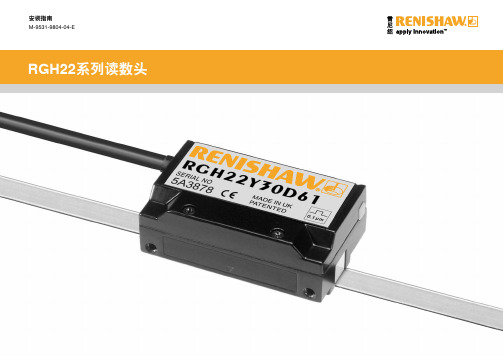
rgh22系列读数头安装手册
honeywell+PRO22R2 Instal

跳线设置:
跳线 J1
J2
J3
位置 OFF ON
5 12 5 12
缺省值 *
* *
表示 端口1 RS-485未使用终端电阻 端口1 RS-232使用终端电阻 读卡器1 5V供电 读卡器1 12V供电 读卡器2 5V供电 读卡器2 12V供电
版权所有©霍尼韦尔国际公司 3
霍尼韦尔安防
DIP开关设置:
S8 S7 S6 S5 S4 S3 S2 S1
霍尼韦尔安防
(RMA)后才能返回厂家。从出厂之日起,Engineered Systems产品有两年的保修期,保修期内,更换故障零件及人工 费全免。但终端设备、打印机、通信产品、升级产品的保质期为90天。保修期内的免费维修只限于产品正常使用。若 由于错误使用、不当贮藏、不当安装、操作或修理、更改、替换、事故、异常损坏或其他物理环境造成产品损坏,则 不在保修之列。
运行模式
LED D79
LED D80
说明
上电时
亮
灭
上电启动,硬件设置
灭
亮
测试RAM
亮
亮
测试ROM,完成初始化
闪
亮
启动完成,D79闪四次
正常运行
闪烁
系统被激活后每秒闪一次。 若亮的时间长一点(0.8秒亮,0.2秒 灭),表示模块处于离线状态,与主控 模块的通信中断;若灭的时间长一点, 表示模块在线,与主控模块的通信正 常。
双读卡器模块的I/O端子只为控制两个门而配置的。插在插板式安装箱中,从下往上端口依次是电源、与主控模块 (PRO22IC)的通信接口、读卡器2接口、与读卡器2相关的I/O接口(称为门磁和开门按钮的输入点,和控制电锁的继 电器输出)、读卡器1接口、与读卡器1相关的I/O接口,最上面的端子是两个额外的可自由使用的通用报警输入端子。
rgh22系列读数头安装手册
RGH22 A、B 1 Vpp模拟(接上文)
15针D型 (L)
4 5 12 13 9 1 10 2 3 11 8 7 6 14 15 壳
12针圆形 (V)
2 12 10 11 5 6 8 1 3 4 不适用 不适用 9 7 11 (连接) 壳
12针圆形联接 器 (W)
2 12 10 11 5 6 8 1 3 4 不适用 不适用 9 7 11 (连接) 壳
甲基化酒精 CH3CHOHCH3
免责声明
Renishaw已尽力保证本文档内容的准确性和完整性。然而,Renishaw对本文档的 内容不作任何担保,尤其对任何隐含的担保不作任何承诺。Renishaw有权对本文档及 本文档所述的产品进行更改,恕不另行通知。
存储与使用
+70 °C -20 °C
+55 °C 0 °C
5V
120R
# 客户端 电子设备
通用规格
电源 5 V ± 5% 120 mA(典型) 200 mA RGH22Y, S, H 注:对于数字输出,电流消耗数字针对的是无端接的读 数头/接口。 当与120 Ω电阻连接时,每对通道(如 A+、A-)会再消 雷尼绍光栅系统必须使用符合标准 N (IEC) 60950 SELV 要求的5 V直流电源。 纹波 密封 加速度 震动 振动 质量 电缆 工作 非工作 工作 读数头 电缆 频率达500 kHz 时,最大200 mVpp IP50 500 m /s² BS EN 60068-2-7:1993 (IEC 68-2-7:1983) 1000 m/s².6 ms.½正弦 BS EN 60068-2-27:1993 (IEC 68-2-27:1987) 55 Hz至2000 Hz时, 100 m/s² BS EN 60068-2-6:1996 (IEC 68-2-6:1995) 45 g 38 g/m 12芯、双屏蔽、最大直径4.7 mm 弯曲半径为50 mm时,挠曲寿命 > 20 x 106次循环 RGH22系列读数头是按照相关EMC标准设计的,但是必须正确安装,才能达到EMC标 准。尤其要注意屏蔽和地线的布置。 注:1M类LED产品。LED辐射。请勿用光学仪器直视。 耗25 mA。
丹尼尔高级超声波气体流量计安装、维修及诊断说明书

重要提示鉴于这些测量仪器为精密仪器,为了确保操作是在设备铭牌所示范围内,因此当你在安装、使用及维护时,必须遵守丹尼尔指南进行。
当在进行安装、使用及维护丹尼尔产品时,应遵守下列提示并将其纳入你的安全工作计划中。
●在进行安装、操作及维修该产品前,应阅读所有说明。
如该手册并非是正确的,请拨打1-713-467-6000(24小时全天侯销售及维修服务支持),尔后将为您提供所需要的手册。
您可保存该手册以供将来参考之需。
●如您对本手册有任何问题不清楚,请联系你的丹尼尔销售代表获得解释。
●请遵照产品所标示及所附的警告、注意事项及说明。
●应教导你的人员进行正确的安装、操作及维护该产品。
●进行安装设备时应按照正确的说明书所指示的要求及当地规范和国家规范。
将所有产品连通适当电源及施加正确的压力。
●为了确保产品的良好性能,应雇用专业的人员进行安装、操作、更新、编排及维护该产品。
●当某部件需要更换时,应确保进行更换工作的专业人员是使用生产商指定的部件。
未经授权的部件及操作流程会对产品的性能产生影响,并会引发操作中的事故隐患。
看起来很相似的替换部件可能会导致火灾、电路短路或不正常的操作。
●为了预防人员受伤,应确保所有设备的门已关闭、保护性的盖子已归位,除非专业人员正在对其进行维修。
●必须始终阅读及遵守《丹尼尔高级超声波气体流量计安装、维修及诊断说明书》和所有产品警告及说明书●如该产品使用于其它非指定用途,可能会导致财产损坏和/或严重人员伤亡。
●在易燃情况下打开产品防火外壳时,必须切断供电。
操作步骤:1. 应先断电。
丹尼尔测量与控制有限公司丹尼尔高级超声波气体流量计安装、维修及诊断说明书注意丹尼尔测量与控制公司(简称丹尼尔公司)不对本说明书的技术或编辑错误及遗漏所负责。
就本说明书而言,丹尼尔公司不作出无论明示或暗示,包含暗示的可为商品性及其适用的目的之保证;并且在任何情况下,丹尼尔公司不对任何特殊及间接损害,包括但不仅限于产品损失及得益损失等等负责。
Columbia Machine 模型22HF、16HF、1600机器的压力 脱头柱安装说明说明书

Knowledge BaseArticle Type: InstructionsCylinder Installation –Compression/Stripper, for Models,22HF, 16HF, 1600 machinesDescription:Instructions on “How to” properly install stripper beam and compression head cylinders. Included is information on the Safety Beam Stops kit.WARNINGNever work on, clean or service this unit, control panel or any machine or open or remove any protective cover, guard, grate, door, or maintenance panel until the power or energy sources has been turned off, locked out / tagged out, and all moving parts have come to a complete stop and or blocked to prevent movement. Machinery is dangerous –avoid personal injury and or death by following manufacture, Local, and OHSA safety procedures. Contact Columbia Machine for safety decals, guards, horns and beacons.INSTALLATION PROCEDURES FOR STRIPPER AND COMPRESSION CYLINDERS FOR FLOOR LEVEL MACHINES MODEL 22, 16 AND 1600Safety First: Always follow your safety guidelines for system lockout/tagout of electrical panels and the hydraulic system.The proper installation for stripper and compression cylinders is very important to ensure good life of the cylinders and their components. It is also important to check the front end of your machine for front-to-back play and side-to-side play as this can lead to shorter life of your cylinders.Upon receiving your compression cylinders or stripper cylinders they should be checked for any damages that may have occurred during shipping. Check the bottoms of the stripper cylinders for nicks or scratches. If noticed, use a flat file single cut fine to remove nicks or scratches. Only remove raised area. Also check for rust at the bottom of the stripper cylinders or any additional rust on the rod ends of the stripper or compression cylinders due to water damages. If light rust is noticed on the bottom of the stripper cylinders, you should use either of the following two hand pads listed below: Hand pad made by 3M Scotch-Brite general purpose color (Maroon) or Bear-Tex made of non-woven nylon web perfect for hand cleaning general all purpose color (Gray)These pads will remove rust and oxidation, and will clean & polish with gentle action and no effect on dimensions. Once cleaned, if you’re not installing them on the machine at this time and will be placing them in the store room, make sure that you coat the base and cylinder rods with a light coat of grease to protect the bare surfaces. Also make sure that either plastic plugs or O-ring plugs are installed in all ports.Please see pictures below for referencing:Clean stripper cylinder base with Scotch-Brite or Bear-Tex hand pads. Using a flat fine tooth file remove any scratches or nicks raised areas only.Using a straight edge check cylinder base for flatness across in three areas: up, down, and diagonally. Check the base foot area of the machine box where the stripper cylinder will mount. Ensure that there are no scratches or nicks and that the surfaces are flat for mounting the cylinders. Make sure to clean all threaded holes thoroughly. Apply a small amount of anti-seize lubricant to the bolts or threaded holes.be made or cylinder damages will occur.You can also verify dimensions by using a straight edge on the top machined surface of the main box and measuring down to the top of the stripper beam. Again these dimensions should be within 1/16 inch from side-to-side. Front end alignment problems could be caused by worn main shafts, bushings, guide tubes, column brackets or stripper beam worn due to guide tube clamp rings not holding guide tubes tight in beam. Lower height stops set incorrectly causing beam to rack or possibly area were stops contact lower stripper beam. For information on adjustment, front end alignment and stripper beam repairs, contact Columbia Machine service department at 1-800-628-4065 for assistance.Stripper cylinder installation:Once you have confirmed the beam is level with the main machine box and the cylinder base and machine foot area is ok cleaned free of scratches or nicks threaded holes cleaned, you are ready to install your stripper cylinders. Make sure you have installed the hydraulic fittings in both the base and rod cap and install the hardened washer on the rod.With stripper beam resting on lower beam stops install the cylinder on machine foot rest area and using anti-seize apply a small amount to either the “new grade 8 bolts orthreaded holes”. Always use new bolts and lock washers when changing out cylinders.Make sure the hardened washer has been installed on the rod assembly. Install the bolts by hand, threading them down as far as possible. Using either a box end wrench orratchet wrench, snug the bolts down in a cross hatch pattern watching the alignment of the rod to the stripper beam where the rod will pass through the beam. Using a torque wrench, tighten the bolts up to torque in three equal settings using a crosshatch pattern.For floor level machines model 22, 16 & 1600, the bolts are a 5/8-18 NF Grade 8 bolts.Full torque is 187 foot pounds lubed. With all bolts torqued to specs, the cylinder rod should pass through the beam without touching the sides of the beam. With thehydraulic hoses attached and the machine slow valve closed for slow operation, begin to raise the rod through the stripper beam making sure the rod does not touch the side of the beam as this can damage the rod seal or cause misalignment with the cylinder causing failure. If the rods move up through the beam without touching, continue to raise the cylinder until the beam is raised to full stroke. Place enough beam stops on the lower height stops and begin to lower the cylinder allowing the rod to disengage from the beam.Make sure the rod, again, is not touching the sides of the beam as it leaves the beam. In the event that the rod is being forced over either when it leaves the beam or will not enter the beam without forcing, back the bolts off at the base and try to move the cylinder over slightly taking up any gap between the holes in the base of the cylinder. Again using a crosshatch pattern begin torquing the bolts down in three equal settings. Once thecylinder has been aligned and the rod can pass through the beam in either the full upposition or down position, you are ready to install the locknut on the rod. Torque the rod locknut to 600 foot pounds on a model 22, 16 or 1600. Columbia Parts has a newlocknut that has more surface area locking against the main beam. The locknut partnumber is 100155.16.Hardened washer.New locknut.With cylinder installed and air evacuated from the cylinder, raisebeam up and down several times, watching both cylinders andbeam for any binding or racking. If all works fine open, slow valveup and back cushions out 1 ½ turns. This is the initial setting.Again raise and lower the beam several times, watching for bindingor racking and to make sure you have a good cushion at the end ofstroke. Once testing has been completed, shut the system down,lock the pump out and apply a small bead of silicone around thebase of the cylinder to the base of the machine foot.Once oil has reached operating temperature, you may need to adjust cushions for smooth cushioning at end of stroke or racking of the beam.Compression cylinder installation:When changing out a compression cylinder or stripper cylinder you should always try tofigure out what may have caused the failure. Contamination to the hydraulic system dueto parts failure or binding of the compression beam or stripper beam, worn or loose frontend allowing the beams to move too much, breaking the rod assembly or damaging therod seal or piston seals. What about the air stroke assembly? Does the air strokeassembly move freely? What’s the condition of the guide rods, bottom support bar,bumper rubber, bushings air bags? Due to the costs of these parts and the lost productiondown time repairs, these questions should be answered as you could possibly lose anothercylinder in a very short time.Locknuts are Columbiamanufactured as the threadsmust be true to the nut facing. The compression cylinder rod is attached to the compression beam through the air stroke assembly. These components must be in good condition and move freely. If binding occurs in the air stroke assembly, this could cause racking of the compression beam which could break the rod assembly or damage the cylinder seals along with other damages that may occur. Inspect these parts and replacement of worn or damage items should be done when replacing a compression cylinder.Prior to installing the cylinder into the stripper beam, install the hydraulic fittings and position them in the right orientation at the base of the cylinder. Clean the threaded holes out in the stripper beam and apply a small amount of anti-seize to the threads or on the bolt threads. Remove the shipping bolt and nut holding the rod cap and bottom plate together. Once removed, be careful not to allow the cylinder tube and cap to separate and slide the compression cylinder down into the stripper beam. Make sure that you position the cylinder so the rod cap porting is facing in the correct orientation to hook up the hoses. Install the (4) socket head bolts threading them into the stripper beam. Using a crosshatch pattern snug the bolts down, but do not torque at this time. Hook up the tube assembly at the base of the cylinder and hose at the rod cap.In the picture above you will notice that the compression rod has a nipple at the threaded end of the rod. When threading the rod into the air stroke assembly bottom support bar, it must be bottom out in the support bar. This ensures that the mating threads of the rod and support bar are seated. Never adjust the cylinder rod out to correct any racking of the beam. The rod must be bottomed out in the support bar. Always use Columbia Machine special jam nuts as they are manufactured with the threads true to the facing. Standard jam nuts are not true 90 degrees to the face. Cylinder rod breakage can occur if not using the Columbia manufactured jam nuts.With bolts installed and hydraulic hoses and tubes hooked up, you are ready to align the rod to the air stroke assembly. As we discussed for stripper cylinder installation, please follow the same procedures for checking beam alignment. Once you have confirmed that the stripper beam is level, true to the block machine main box and you have checked from the top of the stripper beam to the bottom machined surface of the compression beam and both sides are within 1/16 from side-to-side, you can begin to torque the bolts using a crosshatch pattern. Torque the cylinder down to the stripper beam using three equal torque settings. For model 22 socket head cap screw ½ -13 UNC torque to 70 to 80 foot pounds max. Model 16 and 1600 floor level machine 5/8 – 11 UNC torque to 90 to 100 foot pounds max.Columbia manufactured jam nut & compression cylinder rod end.As you are torquing the bolts, watch the rod move around at the top. When you get to your final torque setting, the rod should be aligned with the bottom retainer bar threaded hole. With the jam nuts installed on the rod, run them down to the bottom of the threads and lock them together. Apply anti-seize to the threads. Check to make sure the hydraulic connections are tight. Remove your locks from the pump and main panel making sure the machine slow valve is set for slow operation.Turn the pump on and raise the cylinders just enough so that the nipple of the rod enters the bottom retainer bar. Turn the pump off and lock out the system. Turn the air off the head air bags. With the air off, the air stroke assembly should drop down slightly when the air is evacuated from the air bags. This will allow you to start threading the rod into the bottom retainer bar by hand or with the use of an open end wrench. You should not have to force the rod in or push the rod from side-to-side to start threading the rod in. If you have aligned the rod correctly when you were torquing the cylinder bolts down to the stripper beam you should be able to thread the rod into the bottom retainer bar. Once the rod is bottomed out give a couple hard jerks with the wrench to set the rod tight into the retainer bar. Break the jam nuts loose and tighten each one against the retainer bar and jam nut.On some compression cylinders, rather then a built in cushion on the rod end cap, we have adjustable cushions installed. For initial settings screw the adjusting screw in clockwise until it bottoms out and back out 1 ½ turns. During setup you may need to adjust one side more then the other to eliminate beam racking from side-to-side. Once the oil has warmed to operating temperature you may need to adjust the cushions a little more. Screwing the cushion in clockwise increases cushion out and counter clockwise decreases cushion. Adjust cushions so that the beam does not bang hard at the end of stroke when going up and eliminate side racking of the beam.Cushion adjustment.With the cylinder or cylinders installed you, are ready to make your final settings. Remove locks from system and start pump. Again keeping the slow valve in position for slow operation raise and lower compression beam several times watching for any leaks. Turn head air back on. Place the slow valve in fast operation and run the compression beam up and down. Make sure the stripper beam is in the up position so that full stroke of the cylinder is made. Check for side to side racking of the beam and make adjustments to the cushions. Also adjust cushions just enough so that you have a good cushion at end of stroke going up without the beam banging at end of stroke. Check the down stroke for racking as well. If the beam lags behind on the right side as you begin to start down, back out the cushion slightly. Run the beam up and down several more times. Once the beam can travel to its full up position and down position without racking or banging, you have completed the adjustments. Remember, once the oil warms up to operating temperature, it may be necessary to make adjustments to the cushions again.With both compression and stripper beams in the down position, turn the power off and lock out the system. As an added protection to keep contamination from getting into the threads where the cylinders have been bolted down, it is suggested to apply a small amount of silicone around the base of the cylinders and lock washers. This will aid in keeping the bolts and threads clean from contamination.This completes the stripper and compression cylinder installation. For additional information or service help, please call Columbia Machine Inc. at 1-800-628-4065. Please review information below for Safety Beam Stops application for compression beam and stripper beam for added safety during mold changes, adjustments and repairs.SAFETY BEAM STOPS COMPRESSION BEAM STOPS FOR FLOOR LEVEL MACHINES MODEL 22,16 AND 1600Safety first: Always follow your safety guidelines for system lockout/tagout of electrical panels and the hydraulic system.The installation and use of the new compression beam stops is to maintain compression beam up during mold change, feed drawer strike off plate adjustment or additional repairs or adjustments that require plant personnel to be working in and around the machine with the beam in the up position. The hydraulic circuit for the compression beam on some machines has a P.O. check valve and on others you have a P.O. counterbalance valve. Both these style check valves hold pressure on the base end of the compression cylinder until the valve is energized down which uses pilot pressure to open the check valve or counterbalance valve. In the event that one or both compression cylinders are allowing hydraulic oil to bypass the piston seals the beam will drift down slowly or fast depending on the condition of the seals. Other hydraulic failures can cause the beam to not stay up which could include failure to the P.O. Check valve or P.O. counterbalance valve.The beam stops are a positive stop between the compression beam and stripper beam which in the event that either loss of hydraulics, failure to the compression cylinder or P.O. check valve, P.O. counterbalance valve the beam stops will maintain beam in up position.The following pictures below show the installation of these new positive beam stops:(more pictures next page)LOWER STRIPPER BEAM STOPS FOR FLOOR LEVEL MACHINES MODEL22, 16 AND 1600In addition for mold installation, adjustments or repairs use your lower stripper beam stops to aid in holding the stripper beam in the up position install additional stops as required. The stripper hydraulic circuit also has either a P.O. check Valve or P.O.counterbalance valve that maintains hydraulic oil to the base of the cylinders. The same failures can occur on the stripper circuit as with the compression beam. The mechanical stops are an added safety for maintaining the beam in the up position during moldchanges, cylinder replacements, vibrator & shaker shaft repairs or replacement where you will be required to have your hands in and under the beams.Please see pictured below stripper beam stops:For more information or to order a set of beam stops please contact Columbia Machine, Inc. parts department 1-800-628-4065.Use additional stops as required during mold changes, adjustments or。
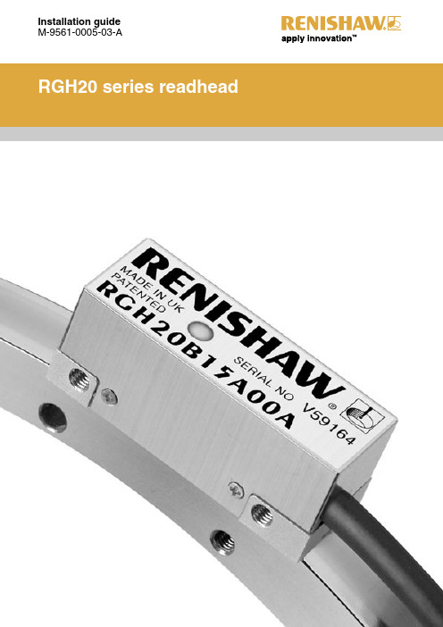
雷尼绍RGH20 读数头按装
A-9559-0650 Reference mark sensor/ limit switch sensor position
Ring centreline and readhead optical centreline
2 mounting holes M3 x 0.5 through 9.5
(Pitch tol. ± 1°)
Readhead set-up To set nominal rideheight, position readhead spacer with the ‘ ’ shaped aperture under the optical centre to allow normal LED function during set-up procedure. Ensure that the scale surface, readhead optical window and mounting face are clean and free from obstructions. NOTE: Ensure readhead fixing screws are tightened to 0.5 Nm to 0.7 Nm.
Disclaimer
Considerable effort has been made to ensure that the contents of this document are free from inaccuracies and omissions. However, Renishaw makes no warranties with respect to the contents of this document and specifically disclaims any implied warranties. Renishaw reserves the right to make changes to this document and to the product described herein without obligation to notify any person of such changes.
取样探头 222.15 17 20 21 31 35 安装及使用说明书

取样探头222.15/17/20/21/31/35安装及使用说明书BC460017, 07/2017 Art. Nr. 90 31 059Bühler Technologies GmbH, Harkortstr. 29, D-40880 RatingenTel. +49 (0) 21 02 / 49 89-0, Fax. +49 (0) 21 02 / 49 89-20AP000005请在安装和使用前仔细阅读此手册。
敬请特别注意所有安全守则,以避免不必要的意外伤害事故。
Bühler Technologies GmbH /德国比勒科技有限责任公司对由不当操作以及在未授权情况下擅自改动机器设备所引起的后果不承担任何责任。
目录页1概述 (4)2重要注意事项 (4)2.1安全注意事项概述 (5)3铭片说明 (6)4产品说明 (6)4.1概述 (6)4.2发货内容 (6)5运输及存储要求 (7)6安装及线路连接 (7)6.1安装 (7)6.2探管的连接 (8)6.2.1样气管的连接 (9)6.2.2校正气体管的连接(可选) (9)6.3反吹和反吹气罐的连接(适用于 GAS 222.21, 31 和 35) (9)6.4电子线路连接 (10)6.4.1型号 GAS 222.15 / GAS 222.17 (10)6.4.2型号 GAS 222.20, 21, 31, 35 (10)6.4.3加热反吹气罐(可选) (11)6.4.4加热扩展件(可选) (11)7操作与维护 (11)7.1安全条款 (11)7.2操作前请检查 (12)7.3探头GAS 222.20, 21, 31, 35 上控制器的功能 (13)7.3.1所有控制器的功能 (13)7.3.2加热扩展件的内置控制器的更多功能(可选) (13)7.3.3内置反吹控制器的功能 (13)7.3.4附加PCB电路板用于电磁阀和限位开关(可选电磁阀控制板) (13)7.4滤芯的维护: (13)7.4.1带顺流过滤器的探头GAS 222.15 (13)7.4.2使用玻璃纤维滤芯的顺流过滤器 (14)7.4.3带顺流过滤器的探头GAS 222.17, 20 和 21 (14)7.4.4带直插过滤器的探头GAS 222.21, 31 和 35 (15)7.5工艺管道中直插过滤器的反吹 (16)7.5.1手动反吹 (16)7.5.2自动反吹 (16)7.5.3内置反吹控制器 (17)7.6控制器的设置 (18)7.6.1菜单选项 (18)7.6.2操作原则详述 (19)7.6.3菜单功能说明 (20)7.6.3.1主菜单 (20)7.6.3.2探头控制器的子菜单(Display: Prob) (21)7.6.3.3加热扩展件控制器的主菜单(display: Adon) (可选) (21)7.6.3.4反吹控制器的子菜单(display: bbc) (可选) (22)8故障及故障排除 (23)8.1备件 (24)9维修及报废处理 (24)9.1报废处理 (24)10制图,证明,数据表 (25)10.1接线图 GAS 222.15/17 (25)10.2接线图 GAS 222.20, 21, 31, 35 (26)10.3加热气罐的连线图 (27)10.4附加文件 (27)1 概述GAS 222.xx系列探头设计安装于气体分析系统内部。
光栅磁栅选型参考资料
雷尼绍和伊莱卡选型指南销售人员在做合同时必须提供具体型号,即唯一确定产品的型号,对该型号的描述可填写在备注栏里。
以下内容供销售人员参考,具体选型需再参考相关文档。
(一)雷尼绍(1)RG2 20μm光栅系列RGH22 D 15 D 00A下划线从左至右编码规则如下:信号分辨率和限位模拟信号A - 1 Vpp (双限位)B - 1 Vpp (单限位)C - 12 μA (限位无效)数字信号D - 5 μm (单限位)P - 5 μm (双限位)X - 1 μm (单限位)Q - 1 μm (双限位)Z - 0.5 μm (单限位)R - 0.5 μm (双限位)Y - 0.1 μm (单限位)S - 0.1 μm (双限位)H - 50 nm (双限位)电缆长度05 - 0.5 m10 - 1 m15 - 1.5 m20 - 2 m30 - 3 m50 - 5 m接口C - 9针 circular plug (RGH22C only)D - 15针D型plug (RGH22D, H, P, Q, R, S, X, Y, and Z only)F –无接口电缆L - 15针D型plug (RGH22A and B only)R - 12针 circular plug (RGH22D, X, Y and Z only - limits not available)S - to be used in conjuction with options 17A and 18A (RGH22B only - limits not available) V – 12针 circular plug for analogue (RGH22B only - limits not available)W - 12针 circular coupling (RGH22B only - limits not available)X - 16针 in-line connector选项00A –标准 (RGH22A, B, C, D, P, Q, R, X, and Z only)17A –模拟输出 1 Vpp, V termination with BID/DIR (RGH22B only)18A –模拟输出 1 Vpp, W termination with BID/DIR (RGH22B only)20A - 3-state error annunciation (RGH22D, P, Q, R, X and Z only)61A - 20 MHz customer clock, (RGH22Y, S, and H only)62A - 10 MHz customer clock, (RGH22Y, S, and H only)63A - 5 MHz customer clock, (RGH22Y, S, and H only)(2) RG4 40μm光栅系列RGH41 B 15 L 00A下划线从左至右编码规则如下:信号分辨率和限位模拟输出A - 1 Vpp (双限位version)B - 1 Vpp (单限位version)数字输出T - 10 μmD - 5 μmG - 2 μmX - 1 μmN - 0.4 μmW - 0.2 μmY - 0.1 μmH - 50 nm电缆长度05 - 0.5 m10 - 1 m15 - 1.5 m30 - 3 m50 - 5 m接口D - 15针D型 plug (RGH41D, G, H, N, T, W, X and Y only)F –无接口电缆L - 15针D型plug (RGH41A and B only)S - to be used in conjunction with option 17A and 18A (RGH41B only -limits not available) V - 12针 circular plug for analogue (RGH41B only - limits not available)W – 12针 circular coupling (RGH41B only - limits not available)X – 16针 in-line connector选项00A–模拟输出 1 Vpp (RGH41A and B only)03A–数字输出, 单限位, differential alarm signal (RGH41D, G, T and X only)04A-数字输出, 单限位, 3 state alarm signal (RGH41D, G, T and X only)05A-数字输出, 双限位, single ended alarm signal (RGH41D, G, T and X only)06A-数字输出, 双限位, 3 state alarm signal (RGH41D, G, T and X only)17A–模拟输出 1 Vpp, V termination with BID/DIR (RGH41B only)18A-模拟输出1 Vpp, W termination with BID/DIR (RGH41B only)61–20 MHz customer clock (RGH41H, N, W and Y only)62–10 MHz customer clock (RGH41H, N, W and Y only)63–5 MHz customer clock (RGH41H, N, W and Y only)(二)伊莱卡产品(1)GS212光栅尺C 1 2 0-5 B –xxxx下划线从左至右编码规则如下选项:D=数显(±10um Accuracy); C=数控(±5um Accuracy)信号输出方式:1=RS422; 2=1Vpp; 3=11uA(DRO only)气压过滤:2=无气压; 3=有气压接口形式: 0=EMS 9D 带铠装; A=EMS 9D 无铠装,PUR(***较常用)3=Acu-rite 9D with armour; A=Acu-rite 9D with PUR4=Fanuc Honda with armour; E=Fanuc Honda with PUR5=HH 15D (female)with armour; F=HH 15D (female)with PUR 分辨率: 1=0.1um; 2=0.5um; 3=1um; 5=5um; 6=10um栅距: B=40um Grating period测量长度:xxxx=Travel in 10mm steps(如0100=1000mm)(2) MG232封闭式磁栅尺D 1 H 0-5 2 –xxxx下划线从左至右编码规则如下选项:D=数显(±10um Accuracy)信号输出方式:1=RS422安装: H:仿海德汉某型号安装尺寸。
RGH22光栅系统-Renishawresourcecentre
可使用特殊配方预涂不干胶和环氧胶粘合的“端压片”将栅 尺固定在轴基体上。这种安装方式可确保栅尺与基体之间的移动 差几乎为零,即使出现较大的温度波动也不受影响。
RGH22系列经验证可应对具有挑战性的工作。许多世界领先 的线性运动系统原始设备制造商 (OEM) 都安装了该系列光栅系 统,涉及的应用领域包括计量、电子、半导体和平板显示器制造 等。
RGH22读数头 • 开放式非接触光学系统 • 内置细分电路 • 行业标准数字和模拟信号选项 • 分辨率从5 µm至50 nm • 内置参考零位和限位传感器 • 集成LED安装指示灯
规格手册 L-9517-9742-01-A
RGH22光栅系统
雷尼绍RGH22系列是一种非接触式光栅系统,可 提供高度可靠的位置反馈。RGH22读数头配有可简化 安装过程的LED安装指示灯、抗污能力优异的独特光 学滤波系统,以及分辨率达50 nm的内置细分电路。
RGH22可提供经验证的可靠性、性能和价值,因此成为最常 用的光栅系统之一。
RGS20栅尺 • 应用灵活,可按需裁剪 • 长度从100 mm至50 m不等 • 保护膜或坚固的聚酯涂层选项,适用于
使用强溶剂的应用场合 • 安装快捷、精准 • 可粘贴在大多数常见的工程材料上 • 背面自带不干胶带 • 安装工具可利用轴运动安装栅尺
规格手册 RGH22光栅系统
RGH22读数头安装图
栅尺的间隙
间隙 0.8 ± 0.1
电源
温度 湿度 防护等级 加速度 冲击 振动 质量 电缆 插头选项
RG中文版安装手册
非接触光栅系统安装与使用指南RGS20-S 、RGS40-S 光栅安装Renishaw (雷尼绍)安装准备1. 剪裁所需光栅,确保光栅的长度能满足行程的要求。
请预留把光栅尺伸延至“起始”标记点。
未到达标记点前,一定要避免光栅尺粘贴到表面上。
确保光栅尺已粘贴到全行程的表面上。
图(1)图(2)备注:必须擦净端压块周边的多余胶水,否则读数头的信号会受影响。
所有型号的光栅上安装,并能多次重复使用。
RGA22GRGA245RGA245RGA22G读数头安装读数头设定图(3)图(3)是一个简单安装支架设计。
螺丝(A) ---- 夹紧读数头,设定Pitch 参数螺丝(B) ---- 设定Yaw 参数和偏移螺丝(C) ---- 可设定Roll 参数安装支架设定固定读数头的托架,必须有平坦表面,能满足读数头安装上的机械公差。
其次必须能调节读数头高度并有足够的稳定性,以预防在读数头工作期间所受到的所有外界影响。
为了减少光栅的安装问题,在未使用光栅安装器(Scale Guide)粘贴光栅前,请先把机械托架的Roll 参数和Yaw 参数调节到读数头的误差范围内,可使用clock gauge 或precision square 完成设定。
对于RGH22、RGH26和RGH41,设定读数头的高度,可透过蓝色和或橙色的校准胶片放置于读数头和光栅尺之间,读数头的LED 安装指示灯显示绿色,表示安装正确。
橙色的校准胶片还可以帮助设定读数头相对于光栅尺的偏移和Yaw 参数 。
对于RGH24和RGH25读数头,设定只可透过蓝色校准胶片放置于读数头和光栅尺之间, 读数头的LED 安装指示灯显示绿色,表示安装正确。
读数头高度设定完成后,以缓慢的速度移动读数头,确保读数头的指示灯在光栅尺的整个行程内都保持绿色。
RGB25和RGH41提供外置设定信号 (X 或Vx),当LED 指示灯失效时,可提供另一个安装参考。
外置设定信号是一个5 V 电源,信号为5 V 表示设定正确,当信号为0 V 时,表示需重新设定。
敞开式光栅尺选型指导手册
127
,
TA-342
82TA0342
3420
135
,
TA-362
82TA0362
3620
143
,
TA-382
82TA0382
3820
150
,
TA-402
82TA0402
4020
158
,
TA-422
82TA0422
4220
166
,
TA-442
82TA0442
4420
174
,
TA-462
82TA0462
mm
inches
(单独订购 )
TG-24
82TG0024
240
9,45
2x PG-10
TG-44
82TG0044
440
17,32
2x PG-20
TG-64
82TG0064
640
25,20
2x PG-30
TG-84
82TG0084
840
33,07
2x PG-40
TG-94
82TG0094
940
37,01
R2 EXPOSED READER HEAD
R2读数头
R2系列读数头可用于EXA、EXG、EXT系列的敞开式直线光栅尺。根据使用要求, 有两种类型的读数头可供选择,RSR系列读数头工作在寻零方式下可读取全部参考点;R2S 系列读数头工作在寻零方式下仅读取所选择的参考点。读数头的型号中指明了信号类型、电缆 长度、接头类型。
组件表
钢带 TG 必选 导向铝壳 PG 必选
读数头 R2 必选 磁性件 M 可选 固定压板 FG-I 可选
- 1、下载文档前请自行甄别文档内容的完整性,平台不提供额外的编辑、内容补充、找答案等附加服务。
- 2、"仅部分预览"的文档,不可在线预览部分如存在完整性等问题,可反馈申请退款(可完整预览的文档不适用该条件!)。
- 3、如文档侵犯您的权益,请联系客服反馈,我们会尽快为您处理(人工客服工作时间:9:00-18:30)。
重要事项:外屏蔽必须连接到机床地线上(励磁接地)。内屏蔽必须连接到0 V线上。注意,须确保内屏蔽和外屏蔽彼此绝 缘。如果内屏蔽和外屏蔽接到一起,将会造成0 V线和地线之间短路,进而导致电子干扰问题。
#
限位输出
V0 V1 V2+ V V V
0 1 2-
建议的信号终端
读数头 A B Z E+
A B Z E-
RGH22C 12 µA模拟
功能
信号 颜色 9针圆形 (C) 同轴插头 (X)
BID DIR 内 外
5V 电源 0V + + + Ve Vx 内 外
褐 橙 白 粉 绿 黄 蓝 红 紫 灰 黑 透明 绿/黄 –
6 – 5 – 8 7 4 3 2 1 – – 9 壳
A E B H G D R F K O P I L 壳
14 7
4 4
3*
9
14.5
23.5
LED 安装指示灯
13
27
2个孔,孔深 M3 x 0.5 x 7.5 A-9531-0251 P限位开关磁励体 使微凹部位朝向基体安装 (与Q磁励体大小相同) P限位开关 传感器位置
10 14.6 14.6 Q限位开关 传感器位置
3
10.5 7.6 A-9531-0251 0.13 Q限位开关磁励体 (滚摆公差 ± 1°) 使微凹部位朝上安装
屏蔽
**注:双限位版本 (A) 使用透明导线(7针)作为VP限位 输出。这些版本没有VX外部安装信号。双限位读数头仅有 F、L或X端子可选。
9针圆形插头(端子代码C)
52 26
I1 增量信号 I2
仅与选项 17 连接 仅与选项 18 连接
参考零位
I0
12针圆形联接器插头(端子代码W)
52 28
RGH22 A、B 1 Vpp模拟(接上文)
15针D型 (L)
4 5 12 13 9 1 10 2 3 11 8 7 6 14 15 壳
12针圆形 (V)
2 12 10 11 5 6 8 1 3 4 不适用 不适用 9 7 11 (连接) 壳
12针圆形联接 器 (W)
2 12 10 11 5 6 8 1 3 4 不适用 不适用 9 7 11 (连接) 壳
为确保单向重复性,需要在设置基准的方向上,将参考零位与光栅尺定相。 在两个方向上均有参考零位脉冲输出,但仅能在定相方向上确保重复性。 读数头须正确安装,以确保在整个行程过程中,LED指示灯一直为绿色。应按照安装 图所示,安装参考零位磁励体。 注:建议将设置基准程序作为开机顺序的一部分来执行,以确保记录正确的基准位置。 注:参考零位输出与增量通道同步,信号宽度为分辨率脉冲宽度。详细信息,请参阅 《RGH22规格手册》(文档编号L-9517-9498)。 定相程序 读数头必须以设置基准的方向移动通过参考零位。LED安装指示灯闪烁红色0.25秒, 表示参考零位已正确定相。如果指示灯闪烁橙色或指示灯熄灭,须逆时针旋转参考零位调 节螺钉 /8 转,并重复上述步骤,直至指示灯闪烁红色。
间隙 0.8 ± 0.1 mm 橙色隔板 或 蓝色隔板 俯仰 0° ± 1° 滚摆 0° ± 1° 扭摆 0° ± 0.5°
参考零位 磁励体 限位开关 磁励体
绿
橙
红
限位开关
读数头传感器经过磁励体时,将输出限位开关信号。 完整输出规格,请参阅《RGH22规格手册》(文档编号L-9517-9498)。
参考零位安装
存储:< 95%最大相对湿度 工作:< 80%最大相对湿度
RGH22安装图
尺寸和公差 mm R50动态弯曲半径 R10静态弯曲半径 A-9531-0250 参考零位磁励体 >6
参考零位传感器位置 光学中心 2个孔,孔深M3 x 0.5 x 9.5 (扭摆公差 ± 0.5°) 0.38 15.5 17* 11.6*
正庚烷
丙酮
H3
氯化溶剂
异丙醇
详细信息
L- 9517 - 9498)和《光栅尺安装指南》(文档编号M-9517-2855)。可从我们的网站 /encoder下载这些资料,也可向当地的雷尼绍业务代表索取。 本文档未经Renishaw plc事先书面许可,不得以任何形式,进行部分或全部复制或 转换为任何其他媒体形式或语言。 出版本文档所含材料并不意味着Renishaw plc放弃对其所拥有的专利权。 有关 RGH 22 读数头的安装详情,另请参阅《 RGH 22 规格手册》(文档编号
甲基化酒精 CH3CHOHCH3
免责声明
Renishaw已尽力保证本文档内容的准确性和完整性。然而,Renishaw对本文档的 内容不作任何担保,尤其对任何隐含的担保不作任何承诺。Renishaw有权对本文档及 本文档所述的产品进行更改,恕不另行通知。
存储与使用
+70 °C -20 °C
+55 °C 0 °C
读数头订货号
RGH22 D 15 D 00A 选项
00A - 标准(仅RGH22A、B、C、D、P、Q、R、X和Z) 17A - 模拟输出1 Vpp,输出BID/DIR信号的V端子(仅RGH22B) 18A - 模拟输出1 Vpp,输出BID/DIR信号的W端子(仅RGH22B) 20A - 三态错误提示(仅RGH22D、P、Q、R、X和Z) 61A - 20 MHz用户可选的时钟频率(仅RGH22Y、S和H) 62A - 10 MHz用户可选的时钟频率(仅RGH22Y、S和H) 63A - 5 MHz用户可选的时钟频率(仅RGH22Y、S和H)
BID/DIR连接 双向操作(正常) BID DIR 单向操作 BID DIR DIR 0V +5 V或未连接 0V 仅正向 仅反向
+5 V或未连接 请勿连接
5V 电源 0V + + + -
至:-
参考零位输出方向
正反方向
V1 增量信号 V2
参考零位 **限位开关 外部安装 参考零位 单向操作
V0 Vq Vx
同轴插头 (X)
A M B N F R D G K O H E I P L 壳
RGH22参考零位输出在正反方向上不可重复。某些控制器在正反方向检测到不同的参 考零位位置时,会显示错误标记。 BID DIR针脚允许要配置的读数头忽略非定相方向上的参考零位脉冲输出(请参阅“参 考零位安装”部分)。 BID/DIR连接
1
连接
RGH22 D、X、 Z、Y、H、P、Q、R、S,RS422A数字
功能
信号
颜色 褐 褐(连接) 白 白(连接)
15针D型 (D)
7 8 2 9 14 6 13 5 12 4 10 11 3 1 15 壳
12针圆形 (R)
2 12 10 11 5 6 8 1 3 4 – 9 7 – 11(连接) 壳
安装指南
M-9531-9804-04-E
RGH22系列读数头
存储与使用(接上文) 符合EMC(电磁兼容性)标准
RG2光栅系统符合下述的相关欧洲统一电磁兼容性标准。 BS EN 61326-1: 2006
专利
雷尼绍的光栅系统及类似产品的功能特点已获得以下专利或已申请专利: EP 0207121 US 4,974,962 JP 2,963,926 US 5,063,685 EP 0543513 US 5,861,953 EP 1147377 JP 1549396 EP 0274492 US 5,088,209 EP 0514081 JP 248,895/1993 EP 826138 B JP 2003-512,611 US 4959542 US 4926566 EP 0388453 JP 3,202,316 US 5,302,820 JP 506,211/1999 US 6,588,333 B1 EP 0274491 EP 0383901 JP 2837483 US 5,241,173 EP 0748436 US 6,051,971
同轴插头(端子代码X)
66 17
报警 外部安装 屏蔽
电气连接
接地和屏蔽
客户端电子设备 RGH22 内屏蔽 延长电缆* 5V 输出信号 0V
外屏蔽
*最大延长电缆长度 RGH22B -100 m,RGH22D、X、Z、P、Q、R- 50 m,RGH22C - 30 m,RGH22Y、S 、H- 20 m
模拟输出 - RGH22 A, B
5 V - 25 V
P Q Vp Vq
也可以使用继电器或光隔离器。
选择R,使最大电流不超过20 mA。
仅安装在报警通道E上,用于失效保护操作
电缆Z0 = 120 R
数字输出 - RGH22 D、X、Z、Y、H、P、Q、R、S,RS422A
R
120R 1k 0V #
1k
‡
3*
箭头表示读数头的正向 (相对于光栅尺) 44 38 最大Ø4.7 (俯仰公差 ± 1°) 0.8 3
详图A
A
光栅尺表面
读数头
光栅尺 厚度0.2
10.6* 2.2*
* 到基体的尺寸 ‡ 其他安装面
5*
2*
读数头与 光栅尺的间隙
间隙 0.8 ± 0.1
读数头安装
安装支架 支架须具备以下特征:安装面平整;确保符合安装公差的要求;允许调整读数头间 隙;具有足够的刚性,防止在操作过程中读数头偏离。为便于读数头安装,在使用适当 的安装工具安装光栅尺前,须调整支架相对于读数头行程轴的滚摆和扭摆。可使用千分 表和精密直角尺进行调整。 读数头安装 要设置标称间隙,放置蓝色或橙色读数头隔板时须使光孔位于光学中心的下方,以 确保在安装过程中LED正常工作。橙色隔板还可以帮助确定读数头相对于光栅尺的偏差 和扭摆。必须保持光栅尺、读数头光学窗口和安装面清洁,无障碍物。 注:确保读数头固定螺钉紧固至0.5 Nm至0.7 Nm。 如果安装正确,LED安装指示灯将变为绿色。缓慢移动读数头,确保在整个轴行程 过程中,LED安装指示灯一直为绿色。 RGH22读数头还具有外部安装信号(X或V),在看不到读数头上的LED指示灯时使 用。在这种情况下,5 V信号表示最佳安装,0 V信号表示须调整安装。 参考零位和限位开关磁励体安装 要定位参考零位和限位开关,须如下图所示使用橙色垫片。 安装详情,请参阅《光栅尺安装指南》(文档编号M-9517-2855)。