外文翻译--计算机辅助工艺过程设计-精品
计算机辅助设计建筑CAD论文中英文对照资料外文翻译文献

中英文对照资料外文翻译文献Computer-aided design (CAD)Computer-aided design (CAD) is the use of a wide range of computer-based tools that assist engineers, architects and other design professionals in their design activities. It is the main geometry authoring tool within the Product Lifecycle Management process and involves both software and sometimes special-purpose hardware. Current packages range from 2D vector based drafting systems to 3D parametric surface and solid design modellers.CAD is sometimes translated as "computer-assisted", "computer-aided drafting", or a similar phrase. Related acronyms are CADD, which stands for "computer-aided design and drafting", CAID for Computer-aided Industrial Design and CAAD, for "computer-aided architectural design". All these terms are essentially synonymous, but there are some subtle differences in meaning and application. Contents IntroductionCAD is used to design and develop products, these can be goods used by end consumers or intermediate goods used in other products. CAD is also extensively used in the design of tools and machinery used in the manufacture of components. CAD is used throughout the engineering process from conceptual design and layout, through detailed engineering and analysis of components to definition of manufacturing methods.Fields of use AEC Architecture Engineering and Construction MCAD Mechanical Automotive Aerospace Consumer Goods Machinery Ship Building ECAD Electronic and Electrical Manufacturing process planningArchitectureThe software package may produce its results in several formats, but typically provides a graphically-based result which is then able to be used to create conceptsketches for assessment and approval, and eventually working drawings. An example would be a structural design package used to assess the integrity of a steel-framed building by performing all the calculations necessary to determine the size and strength of the components, and the effect of such things as wind-loading. The output commonly is a schedule of materials and some basic sketches which can be transferred to a computer-aided drafting package for final production of construction working drawings.Computer-aided drafting, however, commonly refers to the actual technical drawing component of the project, using a computer rather than a traditional drawing board. The input into this aspect of the design process may come from specialised calculation packages, from pre-existing component drawings, from graphical images such as maps, from photos and other media, or simply from hand-drawn sketches done by the designer. The operator's task is to use the CAD software to meld all the relevant components together to produce drawings and specifications which can then be used to estimate quantities of materials, determine the cost of the project and ultimately provide the detailed drawings necessary to build it.The spectrum of architectural and engineering projects commonly documented with computer-aided drafting is broad, and includes architectural, mechanical, electrical, structural, hydraulic, interior design, civil construction. CAD may also provide input to other forms of design communication such as 3D visualisations, model construction, animated fly-throughs, to name a few.Computer-aided drafting software is also a basic tool used in other disciplines related to Architecture, for example Civil Engineering, for site design, for instance roads, grading and drainage, in mapping and cartography, in the production of plans and sketches for a variety of other purposes (such surveyor's plans and legal descriptions of land), and as the input format to geographic and facilities information systems. Additionally, landscape architecture and interior design is often also commonly performed using CAD softwareMechanicalCAD is used in a variety of ways within engineering companies. At its simplestlevel it is a 2D Wireframe package that is used to create engineering drawings. This has however over the last 20 years been overtaken by 3D parametric feature based modelling. Component forms are created either using Freeform surface modelling or solid modelling or a hybrid of the two. These individual components are then assembled into a 3D representation of the final product; this is called bottom-up design. These assembly models can be used to perform analysis to assess if the components can be assembled and fit together as well as for simulating the dynamics of the product. FEA can also be performed on the components and assemblies to assess their strength. Over the last few years, methods and technology have been developed to do top-down design within CAD. This involves starting with a layout diagram of the product; which is broken down into sub-systems with ever increasing detail until the level of single components is reached; geometry in each level being associative with the level above. Detailed design of the individual components is then completed before building up the final product assembly. In general the 3D models are used to generate a 2D technical drawing, this has, however, been slowly replaced by direct transfer of the data to CAM, CNC , Rapid prototyping and Product visualization systems, non geometric information being communicated to down-stream processes with the aid of PMI.Electrical and ElectronicElectronic design automation (EDA) includes PCB design, intelligent wiring diagrams (routing) and component connection management.Manufacturing process planning2D and 3D CAD systems are sometimes used for graphically represented of plant layout, usually with the aid of specific machine geometry libraries and layout tools. Although this is often done with specialist real-time process simulation tools based on Product visualization and Manufacturing Process Management technologies.HistoryDesigners have long used computers for their calculations. Initial developments were carried out in the 1960s within the aircraft and automotive industries in the area of 3D surface construction and NC programming, most of it independent of oneanother and often not publicly published until much later. Some of the mathematical description work on curves was developed in the early 1940s by Isaac Jacob Schoenberg, Apalatequi (Douglas Aircraft) and Roy Liming (North American Aircraft), however probably the most important work on polynomial curves and sculptured surface was done by Pierre Bezier (Renault), Paul de Casteljau (Citroen), S.A. Coons (MIT, Ford), James Ferguson (Boeing), Carl de Boor(GM), Birkhoff(GM) and Garabedian(GM) in the 1960s and W. Gordon (GM) and R. Riesenfeld in the 1970s.It is argued that a turning point was the development of SKETCHPAD system in MIT in 1963 by Ivan Sutherland (who latter created a graphics technology company with Dr. David Evans). The distinctive feature of SKETCHPAD was that it allowed the designer to interact with computer graphically: the design can be fed into the computer by drawing on a CRT monitor with a light pen. Effectively, it was a prototype of graphical user interface, an indispensable feature of modern CAD.First commercial applications of CAD were in large companies in the automotive and aerospace industries, as well as in electronics. Only large corporations could afford the computers capable of performing the calculations. Notable company projects were at GM (Dr. Patrick J.Hanratty) with DAC-1 (Design Augmented by Computer) 1964; Lockhead projects; Bell GRAPHIC 1 and at Renault (Bezier) 每UNISURF 1971 car body design and tooling.The most influential event in the development of CAD was the founding of MCS (Manufacturing and Consulting Services Inc.) in 1971 by Dr. P. J. Hanratty, who wrote the system ADAM (Automated Drafting And Machining) but more importantly supplied code to companies such as McDonnell Douglas (Unigraphics) Computervision(CADDS), Calma, Gerber, Autotrol and Control Data.As computers became more affordable, the application areas have gradually expanded. The development of CAD software for personal desk-top computers was the impetus for almost universal application in all areas of construction.Other key points in the 1960s and 1970s would be the foundation of CAD systems United Computing, Intergraph, IBM, Intergraph IGDS in 1974 (which led to BentleyMicroStation in 1984)CAD implementations have evolved dramatically since then. Initially, with 2D in the 1970s, it was typically limited to producing drawings similar to hand-drafted drawings. Advances in programming and computer hardware, notably solid modelling in the 1980s, have allowed more versatile applications of computers in design activities. Key product for 1981 were the solid modelling packages - Romulus (ShapeData) and Uni-Solid (Unigraphics) based on PADL-2 and the release of the surface modeler Catia (Dassault). Autodesk was founded 1982 by John Walker, which led to the 2D system AutoCAD. The next milestone was the release of Pro/Engineer in 1988, which heralded greater usage of feature based modeling methods. Also of importance to the development of CAD was the development of the B-rep solid modeling kernels (graphics engines) Parasolid(ShapeData) and ACIS (Spatial Technologies) at the end of the 1980s beginning of the 1990s, both inspired by the work of Ian Braid. This led to the release of mid-range packages such as SolidWorks in 1995 SolidEdge (Intergraph) in 1996.Today CAD is not limited to drafting and rendering, and it ventures into many more "intellectual" areas of a designer's expertise.Software providers todayThis is an ever changing industry with many well know products and companies being taken over and merged with others. There are many CAD software products currently on the market. More than half of the market is however covered by the four main PLM corporations Autodesk, Dassault Systemes, PTC, and UGS Corp., but there are many other CAD packages with smaller user bases or covering niche user areas.Packages are can be classified into 3 types: 2D drafting systems (e.g. AutoCAD, Microstation); mid-range 3D solid feature modellers (e.g. SolidWorks, SolidEdge, Alibre); and high-end 3D hybrid systems (e.g. CATIA, NX (Unigraphics)). However these classifications cannot be too strictly taken as many 2D systems have 3D modules, the mid-range systems are increasing their surface functionality, and the high-end systems have developed their user interface in the direction of interactiveWindows systems.CapabilitiesThe capabilities of modern CAD systems include: Wireframe geometry creation 3D parametric feature based modelling, Solid modelling Freeform surface modelling Automated design of assemblies, which are collections of parts and/or other assemblies create Engineering drawings from the solid models Reuse of design components Ease of modification of designs of model and the production of multiple versions Automatic generation of standard components of the design Validation/verification of designs against specifications and design rules Simulation of designs without building a physical prototype Output of engineering documentation, such as manufacturing drawings, and Bills of Materials to reflect the BOM required to build the product Import/Export routines to exchange data with other software packages Output of design data directly to manufacturing facilities Output directly to a Rapid Prototyping or Rapid Manufacture Machine for industrial prototypes maintain libraries of parts and assemblies calculate mass properties of parts and assemblies aid visualization with shading, rotating, hidden line removal, etc……Bi-directional parametric associatively (modification of any feature is reflected in all information relying on that feature; drawings, mass properties, assemblies, etc…… and counter wise) kinematics, interference and clearance checking of assemblies sheet metal hose/cable routing electrical component packaging inclusion of programming code in a model to control and relate desired attributes of the model Programmable design studies and optimization Sophisticated visual analysis routines, for draft, curvature, curvature continuity……Software technologiesOriginally software for CAD systems were developed with computer language such as Fortran, but with the advancement of Object-oriented programming methods this has over the last decade or so radically changed. The development of a typical modern Parametric feature based modeler and freeform surface systems are built around a number of key, C programming language, modules with their own APIs. A CAD system can be seen as built up from the interaction a GUI with an Associativeengine and Geometry constraint engine controlling BREP, CSG and NURBS geometry via a Geometric modeling kernel.Hardware and OS technologiesToday most CAD computer workstations are Windows based PCs; some CAD systems also run on hardware running with one of the Unix operating systems and a few with Linux. Generally no special hardware is required with the exception of a high end OpenGL based Graphics card; however for complex product design machines with high speed (and possibly multiple) CPUs and large amount of RAM are recommended. The human-machine interface is generally via a computer mouse but can also be via a pen and digitizing graphics tablet. Manipulation of the view of the model on the screen is also sometimes done with the use of a spacemouse/spaceball. Some systems also support stereoscopic glasses for viewing the 3D model.计算机辅助设计(CAD)计算机辅助设计(CAD)的广泛使用计算机辅助工具工程师、建筑师和其他设计专业人员设计活动。
外文翻译---计算机辅助设计和计算机辅助(CADCAM)

Computer-aided Design and Computer-aided Manufacturing(CAD/CAM)Throughout the history of our industrial society,many invention have been patented and whole new technologies have evolved .Whitney is concept of interchangeable parts,Watt’s steam engine,and Ford is assembly line are but a few developments that are most noteworthy during our industrial period . Each of these developments has impacted manufacturing as we know it,and has earned these individuals deserved recognition in 0ur history hooks. Perhaps the single development that has impacted manufacturing more quickly and significantly than any previous technology is the digital computer.Since the advent 0f computer technology, manufacturing professionals have wanted to automate the design process and use the database developed therein for automating manufacturing processes. Computer—aided design/computer-aided manufacturing (CAD/CAM),when successfully implemented, should remove the “wall” that has traditionally existed between the design and manufacturing components .CAD/CAM means using computers in the design and manufacturing processes. Since the advent of CAD/CAM,other terms have developed:Computer graphics(CG)Computer—aided engineering(CAE)Computer-aided design and drafting(CADD)Computer aided process planning(CAPP)These spin-off terms a11 refer to specific aspects of the CAD/CAM concept CAD/CAM itself is a broader,more inclusive term. It is at the heart of automated and integrated manufacturing.A key goal of CAD/CAM is to produce data that can be used in manufacturing a product while developing the database for the design of that product When successfully implemented, CAD/CAM involves the sharing of a common database between the design and manufacturing components of a company,Interactive computer graphics (ICG) plays an important role in CAD/CAM, Though the use of ICG, designers develop a graphic image of the product being designed while storing the data that electronically make up the graphic image. The graphic image can be presented in a two-dimensional (2+D) , three-dimensional(3-D),or solids format. ICG image are constructed using such basic geometric characters as points, lines, circles, and curves. Once created, these images can be easily edited and manipulated in a variety of ways including enlargements,reductions, rotations, and movements.An lCG system has three main components :1 ) hardware, which consists of the computer and various peripheral devices; 2) software, which consists of the computer programs and technical manuals for the system ; and 3) the human designer, the most important of the three components.A typical hardware configuration for an ICG System include a computer,a display terminal, a disk drive unit for floppy diskettes, a hard disk, or both; and input/output devices such as a keyboard,plotter, and printer. These devices, along with the software, are the tools modern designers use to develop and document their designs.The ICG systems could enhance the design process by allowing the human designer to focus on the intellectual aspects of the design process, such as conceptualization and making judgment-based decisions. The computer performs tasks for which it is better suited, such as mathematical calculations, storage and retrieval of data,and various repetitive operations such as crosshatching.Rationale for CAD/CAMThe rationale CAD/CAM is similar to that used to justify any technology-based improvement in manufacturing . It grows out of a need to continually improve productivity,quality.and,in turn competitiveness. There are also other reasons why a company might make a conversion from manual processes to CAD/CAM:increased productivitybetter qualitybetter communicationcommon database with manufacturingreduced prototype construction costsfaster response to customersIncreased ProductivityProductivity in the design process is increased by CAD/CAM. Time-consuming tasks such as mathematical calculations.data storage and retrieval, and design visualization are handled by the computer,which gives the designer more time to spend on conceptualizing and completing the design. In addition, the amount of time required to document a design can be reduced significantly with CAD/CAM. All of these taken together means a shorter design cycle, shorter overall project completion time, and a higher level of productivity.Better QualityBecause CAD/CAM allows designers to focus more on actual design problems and lesson time-consuming,nonproductive tasks,product quality improves with CAD/CAM. CAD /CAM allows designers to examine a wider range of design alternatives and to analyze each alternative more thoroughly before selecting one. In addition, because labor-intensive tasks are performed by the computer, fewer design errors occur. These all lead to better product quality.Better CommunicationDesign documents such as drawings,parts lists, bills of material, and specifications are tools used to communicate the design to those who will manufacture it. The more uniform , standardized, and accurate these tools are, the better the communication will be. Because CAD/CAM leads to more uniform, standardized, and accurate documentation, it improves communication.Common DatabaseThis is one of the most important benefits of CAD/CAM. With CAD/CAM.the data generated during the design of product can be use in product the product. This sharing of a common database helps to eliminate the age-old “wall” separating the design and manufacturing functionReduced Prototype CostsWith manual design,models and prototypes of a design must be made and tested, adding to the cost of the finished product. With CAD/CAM,3-D computer models can reduce and, in some case, eliminate the need for building expensive prototypes. Such CAD/CAM capabilities as solids modeling allow designers to substitute computer models for prototypes in many cases.Faster Response to CustomersResponse time is critical in manufacturing. How long does it take to fill a customer’s order? The shorter the time, the better it is. A fast response time is one of the keys to being more competitive in an increasingly competitive marketplace. Today, the manufacturer fastest response time is as likely to win a contract as the one with the lowest bid. By shortening the overall design cycle and improving communication between the design and manufacturing components, CAD/CAM can improve a company’s response timeHistorical Development of CAD/CAMThe historical development of CAD/CAM has followed close behind the development of computer technology and has paralleled the development of ICG technology. The significant developments leading to CAD/CAM began in the late 1950s and early 1960s. The first of these was the development, at Massachusetts Institute of Technology (MIT),ofthe Automatically Programmed Tools (APT) computer programming language.The purpose of APT was to simplify the development of parts programs for numerical control machines. It was the first computer language to be used for this purpose. The APT language represented a major step toward automation of manufacturing processes.Another significant development in the history of CAD/CAM followed close behind APT, also developed at MIT, was called the Sketchpad project. With this project, Ivan Sutherland gave birth to the concept of ICG. The Sketchpad project was the first time a computer was used to create and manipulate graphic images on a CRT display in real time. Throughout the remainder of the 1960s and 70s, CAD continued to develop and several vendors made names for themselves by producing and marketing turnkey CAD systems. These were complete systems including hardware,software,maintenance and training sold as a package. These early systems were configured around mainframe and minicomputer. As a result, they were too expensive to achieve wide-scale acceptance by small to medium manufacturing firms.By the late 1970s,it became clear that the microcomputer would eventually play a role in the further development of CAD/CAM. However, early microcomputers did not have the processing power, memory, or graphic capabilities needed for ICG. Consequently, early attempts to configure CAD/CAM systems around a microcomputer failed.In 1983 IBM Introduced the IBM PC,the first microcomputer to have the processing power, memory, and graphic capabilities to be used in CAD/CAM. This led to a rapid increase in the number of CAD/CAM vendors. By l989 the number of CAD/CAM installations based on microcomputers equaled the number based on mainframe and minicomputer.Computer and DesignThe computer has had a major impact on the way everyday tasks associated with design are accomplished. It can be used in many ways to do many things. However, all design tasks accomplished using a computer fall into one of three broad categories:Design modelingDesign analysisDesign reviewIn CAD/CAM design modeling, a geometric model of a product is developed that describes the part mathematically. This mathematical description is converted to graphic form and displayed on a cathode ray tube. The geometric model also allows the graphic image to be easily edited and manipulated once displayed.Design AnalysisThe computer has simplified the design analysis stage of the design process significantly. Once a proposed design has been developed, it is necessary to analyze how it will stand up to the conditions to which it will be subjected. Such analysis methods as heat transfer and stress-strain calculations are time-consuming and complex. With CAD/CAM, special computer programs written specifically for analysis purposes are available.Design ReviewAnother step in the design process that has been simplified by the computer is design review. This involves checking the accuracy of all aspects of the design. There are several ICG capabilities that make design review in CAD/CAM easier than with manual design. CAD-to-CAM InterfaceWith CAD/CAM, the real interface between the design and manufacturing components is the common database they share. This is the essence of CAD/CAM. With manual design and manufacturing, engineers go through each step in the design, drafters produce drawings and other documents to communicate the design, manufacturing personnel use the drawings to develop process plans,and shop personnel actually make the product.With the old approach,until the design and drafting personnel completed their work, the manufacturing personnel did not see it. The design and drafting department did its job and“threw the plans over the wall”to manufacturing so it could do its job. This approach led to continual breakdowns in communication as well as poor relations between the design and manufacturing components. The result was a loss of productivity.With CAD/CAM.manufacturing personnel have access to the data created during the design phase as soon as they are created. At any point in the design process, they can call up information from the design database and use it. Since the data are shared from start to finish, There are no surprises when the completed design is ready to be produced. While designers are creating the database and drafters are documenting the design,manufacturing personnel can be programs.Everything needed by manufacturing personnel to produce the product is contained in the common database. The mathematical models, graphic images,bills of material,parts lists,size,from. locational dimensions, tolerance specifications and material specifications are all contained database计算机辅助设计和计算机辅助(CAD/CAM)纵观人类工业社会的历史,许多发明获得了专利,整个新技术也逐渐形成。
电脑辅助设计翻译

电脑辅助设计计算机辅助设计(CAD),也)被称为电脑辅助设计及绘图(计算机辅助药物设计,是利用计算机技术进行设计和工艺文件的设计。
电脑辅助绘图介绍了用电脑起草进程。
计算机辅助药物设计软件,或环境,提供了简化设计流程的目的与输入工具的用户,起草,文档和制造工艺。
计算机辅助药物设计输出通常在为印刷或电子文件的形式加工业务。
在计算机辅助药物设计的软件开发是直接相关的过程与它力求节约,工业为基础的软件(建筑,制造等),而通常使用的图形为基础的软件载体为基础的(线性)环境采用基于光栅(像素化)环境。
计算机辅助药物设计的环境中往往涉及的不仅仅是形状。
正如在本手册起草的技术和工程图纸,民航处输出必须传达的信息,如材料,工艺,尺寸,和公差,根据应用特定的约定。
计算机辅助设计,可用于设计和数字,曲线两维(二维)空间;或曲线,曲面和固体中的三维(3D)的对象。
[1]CAD是一种重要的工业美术广泛,应用在许多方面,包括汽车,造船,航空航天工业,工业和建筑设计假肢,等等。
民航处也被广泛用于制作电脑动画的特效电影,广告和技术手册。
现代计算机的普及和权力的手段,甚至香水瓶,洗发水饮水机的设计采用20世纪60年代由工程师技术闻所未闻的。
由于其巨大的经济意义,民航处一直在研究的主要驱动力一计算几何,计算机图形学(包括硬件和软件),与离散微分几何。
[2]对设计的几何模型为对象的形状特别,中,通常被称为计算机辅助几何设计(CAGD)。
[3]20世纪80年代的计算机辅助设计项目开始减少了显着的起草人需要,特别是在小到中型公司。
他们的负担能力,有能力的个人电脑上运行的工程师也可以自己做起草工作,消除了对整个部门的需要。
在今天的世界上大多数,如果不是全部,在大学的学生不学习,因为他们起草无须这样做的技术。
手的日子最终图纸绘制几乎已经过时。
高校不再需要使用的量角器和圆规来创建绘图,而不是有几个类的CAD软件,如专业工程师或国际环境协定,微软使用的重点。
计算机辅助工艺设计

计算机辅助工艺设计发展史与发展趋势姓名:专业:学号:摘要计算机辅助工艺设计(Computer Aided Process Planning,简称CAPP)是借助于计算机软硬件技术和支撑环境,利用计算机进行数值计算,逻辑判断和推理等的功能来制定零件机械加工工艺过程。
借助于CAPP系统,可以解决手工工艺设计效率低、一致性差、质量不稳定、不易达到优化等问题。
智能化的CAPP系统可以继承和学习工艺专家的经验和知识,用于指导工艺设计,在一定程度上可以弥补技术熟练、具有丰富生产经验的工艺专家普遍存在不足的缺憾。
所以CAPP自诞生以来,一直受到工业界和学术界的广泛重视。
CAPP是将产品设计信息转换为各种加工制造、管理信息的关键环节,是连接CAD、CAM的桥梁,是制造业企业信息化建设的信息中枢,是支撑CIMS(Computer Integrated Manufacturing system)的核心单元技术,作用和意义重大。
关键词智能化并行工程敏捷制造先进制造技术一.国内外CAPP发展史CAPP系统的研究和发展经历了较为漫长曲折的过程。
自从1965年Niebel 首次提出CAPP思想[1],迄今30多年,CAPP领域的研究得到了极大的发展,期间经历了检索式、派生式、创成式、混合式、专家系统、开发工具等不同的发展阶段,并涌现了一大批CAPP原型系统和商品化的CAPP系统。
早期的CAPP系统为检索式(Retrieval)系统[2]。
它事先将设计好的零件加工工艺规程存储在计算机中,在编制零件工艺规程时,根据零件图号或名称等检索出存有的工艺规程,获得工艺设计内容。
这类CAPP系统自动决策能力差,但最易建立,简单实用,对于现行工艺规程比较稳定的企业比较实用。
检索式CAPP 系统主要用于己经标准化的工艺过程设计。
随着成组技术(GT)的推广应用,变异式或派生式CAPP(Variant CAPP)系统得到了开发和应用。
派生式CAPP系统以成组技术为基础,按零件结构和工艺的相似性,将零件划分为零件族,并给每一族的零件制定优化的加工力一案和典型工艺过程。
精选CAM第2章计算机辅助工艺过程设计kdk
非切削加工
弯曲方向
弯曲角度
外平面
外曲面
主成形面
周期面与辅助成形面
方向与阶梯
螺纹与成形面
方向
形状
特殊孔
非回转体零件分类编码系统结构
码位
0
回转体零件
零件名称类别粗分
零件名称类别细分
1
2
3
4
5
非回转体零件
6
7
8
9
0
材料
毛坯原始形状
热处理
主要尺寸
精度
1
直径和宽度
长度
2
3
4
5
6
7
8
9
1
2
3
4
5
6
7
8
9
9、静夜四无邻,荒居旧业贫。。10、雨中黄叶树,灯下白头人。。11、以我独沈久,愧君相见频。。12、故人江海别,几度隔山川。。13、乍见翻疑梦,相悲各问年。。14、他乡生白发,旧国见青山。。15、比不了得就不比,得不到的就不要。。。16、行动出成果,工作出财富。。17、做前,能够环视四周;做时,你只能或者最好沿着以脚为起点的射线向前。。9、没有失败,只有暂时停止成功!。10、很多事情努力了未必有结果,但是不努力却什么改变也没有。。11、成功就是日复一日那一点点小小努力的积累。。12、世间成事,不求其绝对圆满,留一份不足,可得无限完美。。13、不知香积寺,数里入云峰。。14、意志坚强的人能把世界放在手中像泥块一样任意揉捏。15、楚塞三湘接,荆门九派通。。。16、少年十五二十时,步行夺得胡马骑。。17、空山新雨后,天气晚来秋。。9、杨柳散和风,青山澹吾虑。。10、阅读一切好书如同和过去最杰出的人谈话。11、越是没有本领的就越加自命不凡。12、越是无能的人,越喜欢挑剔别人的错儿。13、知人者智,自知者明。胜人者有力,自胜者强。14、意志坚强的人能把世界放在手中像泥块一样任意揉捏。15、最具挑战性的挑战莫过于提升自我。。16、业余生活要有意义,不要越轨。17、一个人即使已登上顶峰,也仍要自强不息。
第六章计算机辅助工艺设计
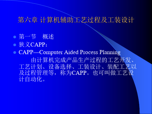
第二节 CAPP系统的工作模式
CAPP的工作过程
第二节 CAPP系统的工作模式
零件信息描述的基本方法:
零件信息描述
零件分类编码描述法 形状特征描述法 语言描述法 知识表示描述法
CAD-CAPP
第二节 CAPP系统的工作模式
零件分类编码描述法:基于成组技术原理, 采用编码系统
特点:简单易行,适用于检索式与派生式 CAPP系统。
编制标准工艺文件存储于数据库,然后,对按 待加工零件的类别检索工艺。
⑵创成法:计算机根据知识库存储的知识, 对待加工零件进行分析,通过推理、决策,确 定加工工艺。
第二节 CAPP系统的工作模式
CAPP系统应具有的基本功能 ⑴检索标准工艺文件 ⑵选择加工方法 ⑶安排工艺路线 ⑷选择机床、刀具、夹具、量具 ⑸选择切削用量 ⑹计算切削参数、加工时间、加工费用 ⑺确定工序尺寸和公差、选择毛坯 ⑻绘制工序图 ⑼给出刀具运动轨迹,自动进行NC编程 ⑽加工过程模拟
缺点:对零件信息的描述过粗,对零件的 具体形状、尺寸、精度描述不是十 分清楚。
第二节 CAPP系统的工作模式
形状特征描述法:将组成零件的各个特征 按一定顺序逐个地输入到计算机中去。
特点:特征与加工方法对应,方便加工方 法确定; 包含了尺寸、公差、粗糙度以及热 处理。
缺点:这种方法比较繁琐、费时。
第二节 CAPP系统的工作模式
第一节 概述
国内主要CAPP软件: 1. 机械加工工艺手册(软件版) 2. 金叶CAPP 3. 开目 CAPP 4. 天河工艺设计(TH-CAPP)
第二节 CAPP系统的工作模式
Capp系统的工作原理 到目前为止,国内外发表的CAPP系统分两大
类,其工作原理为派生法(检索法)和创成法。 ⑴派生法:根据成组技术将工件分类,按类
计算机辅助工艺CAPP

创成式CAPP系统特点
•
创成式CAPP系统一般不需要人工干预,自动
化程度较高,且决策更科学,更具有普遍性。但由于
目前工艺过程设计经验的成分居多,理论还不完善,
完全使用创成方法进行工艺过程设计还有一定的困难。
计算机辅助工艺过程设计-computer aided process planning
– 缺点:派生式CAPP系统由于通常以企 业现有工艺规程为基础,具有较浓厚的企 业色彩,因而有较大的局限性。
计算机辅助工艺过程设计-computer aided process planning
• 2. 创成式CAPP系统
• 创成式CAPP系统与派生式CAPP系统不同,它不是依靠对已有 的标准工艺规程进行编辑和修改来生成新的工艺规程,而是 根据输入的零件信息,按存储在计算机内的工艺决策算法和 逻辑推理方法,从无到有地生成零件的工艺规程。
•
例:普渡大学开发的APPAS(Automated Process
Planning and Selection)系统是一个基于创成方法的实验
性CAPP系统,该系统主要用于非回转类零件表面加工方法的
自动生成。其原始依据是每一种加工方法均对应于一定的工
作范围。例如,采用麻花钻钻孔的工作范围如下:
•
最大钻孔直径:Dmax = 2″
•
最小钻孔直径:Dmin = 0.0625″
•
孔径上偏差:
•
孔径下偏差:
•
孔的位置精度:±0.008″
•
孔的表面粗糙度:Ra = 200μm
•
孔的长径比:L / D<12
•
将每一种加工方法所对应的工作范围以文件或数据库的
形式存储在计算机内,并建立一定的逻辑关系,通过运行相
计算机辅助工艺设计CA

25
五、CAPP的基本类型
6. 智能CAPP系统
工作原理:将人工智能技术应用在CAPP系统。 特点:加入推理机制。以人工智能、专家系统技术为基础的CAPP系统。强
调工艺设计系统中工艺知识的表达、处理机制以及决策过程的自动化。 创成式CAPP:“逻辑算法+决策表” 专家系统CAPP:“逻辑推理+知识” 上世纪80年代法国的Descotte开发第一个利用人工智能技术的CAPP系统- GARI系统
传统 量大、效率低
长
差
差
信息无法集成
CAPP 量轻、效率高
短
好
好
有利于实现
CIMS
精选ppt
13
13
四、CAPP发展过程和趋势
1965年由挪威人Niebel首次提出 CAPP思想
1976年推出CAM-I’S Automated Process Planning.
经历了检索式、派生式、创成式、 混合式、专家系统、开发工具等 不同的发展阶段
精选ppt
26
26
CAPP
CAPP
工作原理
零件类型 工艺类型 系 统 工艺数据组织形式 系统实现技术 与其它系统的集成
检索式CAPP 派生式CAPP 创成式CAPP 混合式CAPP 专家系统CAPP
回转体零件 非回转体零件
机加工CAPP 焊接CAPP 。。。。。。 装配CAPP
箱体类零件 盘套类零件 杆件类零件 板块类零件
精选ppt
17
17
四、CAPP发展过程和趋势
CAPP系统发展的热点和趋势
1. 产品信息模型的生成与获取 2. CAPP体系结构研究及CAPP工具系统的开发 3. 并行工程(CE)模式下的CAPP系统 4. 基于分布型人工智能技术的分布型CAPP系统 5. 人工神经网络技术与专家系统在CAPP中的应用 6. 面向实用化的CAPP系统 7. CAPP与自动生产高度系统的集成
- 1、下载文档前请自行甄别文档内容的完整性,平台不提供额外的编辑、内容补充、找答案等附加服务。
- 2、"仅部分预览"的文档,不可在线预览部分如存在完整性等问题,可反馈申请退款(可完整预览的文档不适用该条件!)。
- 3、如文档侵犯您的权益,请联系客服反馈,我们会尽快为您处理(人工客服工作时间:9:00-18:30)。
Computer-Aided Process PlanningAccording to the Tool & Manufacturing Engineers Handbook, process planning is the systematic determination of the methods by which a product is to be manufactured economically and competitively. It essentially involves selection, calculation, and documentation. Processes, machines, tools, operations, and sequences must be selected. Such factors as feeds, speeds, tolerances, dimensions, and costs must be calculated. Finally, documents in the form of illustrated process sheets, operation sheets, and process routes must be prepared. Process planning is an intermediate stage between designing and manufacturing the product. But how well does it bridge design and manufacturing?Most manufacturing engineers would agree that, if ten different planners were asked to develop a process plan for the same part, they would probably come up with ten different plans. Obviously, all these plans cannot reflect the most efficient manufacturing methods, and, in fact, there is no guarantee that any one of them will constitute the optimum method for manufacturing the part.What may be even more disturbing is that a process plan developed for a part during a current manufacturing program may be quite different from the plan developed for the same or similar part during a previous manufacturing program and it may never be used again for the same or similar part. That represents a lot of wasted effort and produces a great many inconsistencies in routing, tooling, labor requirements, costing, and possibly even purchase requirements.Of course, process plans should not necessarily remain static. As lot sizes change and new technology, equipment, and processes become available, the most effective way to manufacture a particular part also changes, and those changes should be reflected in current process plans released to the shop.A planner must manage and retrieve a great deal of data and many documents,including established standards,mach inability data,machine specifications,tooling inventories,stock availability,and existing process plans.This is primarily an information—handling job,and the computer is an ideal companion.There is another advantage to using computers to help with process planning.Because the task involves many interrelated activities,determining the optimum plan requires many iterations. Since computers can readily perform vast numbers of comparisons,many more alternative plans can be explored than would be possible manually.A third advantage in the use of computer-aided process planning is uniformity. Several specific benefits Can be expected from the adoption of computer-aided process—planning techniques:1.Reduced clerical effort in preparation of instructions.2.Fewer calculation errors due to human error.3. Fewer oversights in logic or instructions because of the promptingcapability available with interactive computer programs.4.Immediate access to up—to—date information from a central database.5.Consistent information,because every planner accesses the same database.6. Faster response to changes requested by engineers of other operatingdepartments.7.Automatic Use of the latest revision of a part drawing.8. More—detailed,more—uniform process-plan statements produced byword—processing techniques.9.More—effective use of inventories of tools,gages,and fixtures and a concomitant reduction in the variety of those items.10. Better communication with shop personnel because plans can be morespecifically tailored to a particular task and presented in unambiguous,proven language.11. Better information for production planning, including cutter-life,forecasting, materials-requirements planning, scheduling, and inventorycontrol.Most important for CIM, computer-aided process planning produces machine-readable data instead of handwritten plans. Such data can readily be transferred to other systems within the C1M hierarchy for use in planning.There are basically two approaches to computer-aided process planning: variant and generative.In the variant approach, a set of standard process plans is established for all the parts families that have been identified through group technology. The standard plans are stored in computer memory and retrieved for new parts according to their family identification. Again, GT helps to place the new part in an appropriate family. The standard plan is then edited to suit the specific requirements of a particular job.In the generative approach, an attempt is made to synthesize each individual plan using appropriate algorithms that define the various technological decisions that mustbe made in the course of manufacturing. In a truly generative process-planning system, the sequence of operations, as well as all the manufacturing-process parameters, would be automatically established without reference to prior plans. In its ultimate realization, such an approach would be universally applicable: present any plan to the system, and the computer produces the optimum process plan.No such system exists, however. So called generative process-planning systems--and probably for the foreseeable future---are still specialized systems developed for a specific operation or a particular type of manufacturing process. The logic is based on a combination of past practice and basic technology.计算机辅助工艺过程设计根据《工具与制造工程师手册》,工艺过程是能够经济地和有竞争力地将产品制造出来的一整套方法。