换热站自动控制系统设计外文文献+翻译
套管换热器英文文献翻译
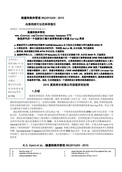
能量转换和管理98(2015)69 - 2015内容列表可以在科学指引爱思唯尔(世界领先的科技及医学出版公司)能量转换和管理/locate/enconman homepage 日刊数值研究的一个创新设计翅片套管换热器与变量fin-tip 厚度a.高级研究中心纯粹和应用数学(CASPAM)Bahauddin 扎卡里亚正在搜索大学巴基斯坦68000年b.计算机科学、通讯卫星信息技术研究所、韦校园,Mailsi 路,木尔坦路,韦巴基斯坦c.数学系,政府爱默生学院60700年木尔坦,巴基斯坦d.基础科学和人文、工程科技大学Bahauddin 扎卡里亚正在搜索大学,木尔坦68000年,巴基斯坦 分析充分发展的层流对流换热翅片的一个创新设计套管换热器(DPHE)和纵向鳍的变厚度提示受到施加力传热速率边界条件研究。
尖厚度控制的小费比底角作为参数的值从0到1对应于不同翅片形状不同的三角形和矩形截面。
到作者的知识,这个参数是首次被引入文学。
间断伽辽金有限元法(DG-FEM)从事目前的工作。
的整体性能提出DPHE 调查了考虑摩擦因素,努塞尔特数和j 因子。
努塞尔特数高达178%和89%的涨幅取得了j 因子相对rectangu-lar 横截面。
这样的收益相对于三角形截面分别为9.5%和19%。
结果表明,新引入的参数提示比底角证明发挥重要作用在套管换热器的设计在降低成本、重量和摩擦损失,提高换热器的传热速率和节能。
因此,它必须被视为一个重要的设计参数对换热器的设计。
2015爱思唯尔有限公司保留所有权利 1.介绍 随着技术的进步,传热工程的重要性增加,总有一个在这方面需要满足新的设计挑战了高性能传热特别是由于能源问题。
通常,热交换器广泛用于这一目的。
有很多技术,用来提高换热器的传热速率但最有效的其中之一是使用安装鳍。
换热器的设计取决于许多特性即上浆、紧凑,传热性能估算,经济方面和压降分析。
目前的调查描述了数值研究的创新设计翅片套管换热器的变量fin-tip 厚度。
换热站自动控制系统设计外文文献+翻译
外文文献:Design and Implementation of Heat Exchange Station Control SystemKeywords:Heat exchange station, Control system, PLC, Inverter, Configuration software.Abstract.This paper introduces a design and implementation of heat exchange station control systembased on PLC and industrial configuration software, which includes the contr ol scheme and principle,hardware selection and software design, etc. The circulating pumps and re plenishing pumps in thesystem can all be driven automatically by PLC and inverter. Main process parameters, such as steampressure and measurement temperature and so on,can all be shown on the industrial PC runningconfiguration software, and instructions could be sent by the engineer and operator on-the-spot via theHuman Machine Interface as well. The automatic pressures adjustment of stea m supply of the heaterby advanced PID algorithm has been realized finally. It is verified that the system is highly reliableand stable, and it greatly enhances the level of automation and pressure control accuracy of the heatexchange station and meets all the equipments running demands well. IntroductionWith the rapid development of economy and society, heat supply systems are the key power source inthe communities and plants in China. As a media between heat sources and heat loads in the systems,a heat exchange stations plays a very important role for the heat supplyquality. Traditionally, most ofthe pumps in the heat supply systems are operated by valves manually, s o it could bring about thepower energy consuming, high labor intensity and low operation automation. I n this paper a design ofcontrol system for heat exchange station based on PLC, inverter and indust rial configuration softwarewas proposed,accordingly the aim for power energy saving,high heat efficiency and operationautomation has been achieved.Process outline and Control demandsProcess outline.The process outline and control demands were put forward at first before the schemeand design of heat exchange station control system were proposed.Heat exchange station consists of a steam-driven heater,plus3ci rculating pumps,2replenishingpumps and electric control valve. By adjusting the steam flux into the mixture of water and steamaccording to the temperature sensors mounted indoors and outdoors, the pr ocess of heat exchangecould be completed. Among these equipments, the steam-driven heater, a heat exchanger containingmixture of steam-and-water, is the key appliance for heat supply system.Control demands.Major control demands for the control system were listed a s follows [1]:(a)Pumps driving.Pumps include3circulating pumps(2in operation,1for backup)and2replenishing pumps (1 in operation, 1 for backup). Among circulating ones one is driven by powerfrequency, the others are driven by variable frequency, with 75KW power ea ch; among replenishingones one is driven by power frequency, the other is driven by variable frequency, with 3KW powereach. The control signal should be originated from the pressure difference between the supply waterand return water.Pumps could be driven in stepless speed regulating when connecting variablepower;(b)Parameters Showing.The showing parameters contain temperatureshowing-temperature ofsupply water, return water, the indoor, the outdoor and steam - and pre ssure showing - pressure ofsupply water, return water and pre-valve and post-valve of the steam etc;(c) Butterfly valves driving.Two butterfly valves can be on or of f automatically when the wholesystem start or stop;(d) Motor-driven valves control. By continuously adjusting the opening of t he valves according to thesignal from the temperature sensors indoors and outdoors, the supply wate r temperature should bestabilized in the presetting values;(e) HMI (Human Machine Interface) Demands. The process flow chart of heatexchange station andmain process parameter can be shown in HMI, and instructions can be trans mitted via this interface;(f) Safeguard Function. The circulating pumps should be out of running when heat exchange system isin water needing, and steam should be kept out of the heater when the pumps are not revolving.Hardware Selection of the Control SystemFrom the control demands mentioned above, the controller of the control s ystem can process signalsboth relay and analog, having the ability of loop adjustment of analog q uantity. At the meantime thepumps could run in the working condition of variable frequency, so the hardware selection of thecontrol system for heat exchange station should be made deliberately.PLC Serving as Main Controller.As some experienced electrica l engineers known,PLC/PC(Program Controller) is a kind of popular industrial computer, and it can not only accomplish logiccontrol, but also complete many advanced functions, such as analog quanti ty loop adjustment, andmotion control, etc. According to the component amounts of input and outpu t and the needs of controlsystem, FX1N-60MR micro PLC of MITSUBISHI FX series is selected, which hav ing 36 inputs and24 outputs, and doing analog adjustment by using advanced instruction likePID instruction [2].Because of the sampling and driving of the analog signal necessarily, P LC should be extended toanalog input/output function module like FX2N-4AD (4AD) and FX2N-4DA (4DA) or somethinglike.On one hand,4AD adopted is an analog input module having4channels with12bit highresolution, which could receive 0~+10V voltage signal, 0~20mA or 4~20mA cu rrent signal. On theother hand, 4DA chosen could send standard voltage signal and/or current signal, having 4 channelswith 12 bit high resolution also. It is something to be mentioned here , the wiring form of currentinput/output (4~20mA) must be adopted in order to avoiding the strong elec tromagnetism disturbancein the working field [3].Inverter completing Stepless Speed Regulating.At present, inverter, as an im port power electronicconverter, can convert constantly power frequency into continually variable frequency. Thus, energysaving, cost consuming and noise reduction can be easily reached by this equipment.In this control system inverter of ACS510 series of ABB Corporation were elaborately chosen, whichhas many advantages, such as Direct Torque Control (DTC) and advanced appl ying macro and so on.Its main good points and characteristics are illustrated as follows: it can acquire maximum startingtorque (200% normal torque) by using direct excitation; it can be applied to multiple driving systemsby using master-slave function;input and output programmable function;high precision of speedregulating, perfect safeguard and alarming steps. Owing to these highlights of this inverter, pumpsdriving of stepless speed regulating can be easily obtained.There are many applying macro inACS510 series, but we should only choose manual/automatic macro here as we need.IPC Acting as Monitor&Control Interface.IPC(Industrial Personal Computer)has strongcompatibility,extensibility and reliability,which can connect PLC by RS-232serial portconveniently. In the hardware configuration we select IPC H610 series of A DVANTECH as HMI.MCGS(Monitor Control Generated System),fashionable home-mad e industrial configurationsoftware, is running on the ADVANTECH IPC. Using this HMI, the visualizati on process of Monitorand Control is realized easily, intuitively and vividly.With the sensor/transducer,analog input/output modules,PLC a nd actuators,.inverter andmotor-driven valve, the loop adjustment of steam pressure can be precisely attained, and temperatureof all measure points could be measured also[4].The overall hardware configuration of heatexchange station control system see Fig. 1.Fig. 1 The overall hardware configuration of heat exchange station control systemSoftware Design of the Control SystemLAD Diagram Programming.Out of the thoughts of modular programming, the whole programstructure can be divided into such several modules as Initialization Function,upper IPCCommunication Function, Relay Control Function, Analog Sampling, Fuzzy PID Adjust Functionand Safeguard Function, etc. The flow chart of LAD diagram programming of PLC is shown in Fig. 2.Among these modular functions, it is something worthy to mention of Fuzzy PID Adjust Function.Under some circumstances the using of PID instruction of PLC was not so good at what we expected;therefore, the self-made program of Fuzzy PID adjustment of steam pressure was done from deviationand deviation acceleration of temperature between the indoor and the outdoo r in accordance with theFuzzy Control Theory and its application [5].HMI Configuration.For the sake of the appearance beauty and personalizati on between machineand human, the MCGS- Monitor Control Generated Software of Beijing MCGS Tech Co. Ltd wasadopted. This industrial configuration software has very quick, easy devel opment of configurationprocess, which can build bi-directional and high speed communication betwee n PLC and upper IPCthru RS422/232 serial port.In the development environment of MCGS, all needed windows and pictures we re created, includingMain Window of Process Flow, Process Parameters Showing Window, and Key P arameters SettingWindow, etc. Vivid and readily interaction between human and machine can be completed by suchbeautiful pictures and animations when IPC running MCGS.ConclusionsThis design of heat exchange station control system based onFX series PLC,MCGS,and ABBinverter has been realized the pressure automatic adjustment of steam-driven heater as originallyexpected.More over,design demands of power energy savi ng,high heat efficiency and lowequipments noise can all be well met. Finally, the practical operation ver ifies that the system is highlyreliable and stable, and it greatly enhances the level of automation and pressure control accuracy ofheat exchange station and meets equipments requirements of energy saving an d green driving.BEGINInitializationFuzzy PIDAdjust FunctionCommunicationFunctionAnalog OutputNoRelay ControlFunctionAnalog FilteringFunctionCall AnalogSample FunctionSample OverYesAnalog InputLinear TransferLinear TransferAnalog OutputDrivingSafeguard FunctionFailure OccurNoYesFailure HandlingRelated MemoryResetENDFig. 2 The flow chat of LAD diagram programming of PLCAcknowledgementComposition of this paper was with the help and under the direction ofSenior Engineer Nian-huiZhang of Qingdao Wellborn Automation Corporation.References[1]Information on H. Zhang, . Li:The Principle of PLC with itsApplications to Process Control(China PowerPress, Beijing 2008).[3]H. Zhang:The Design and Development of MITSUBISHI FX Series PLC( China Machine Press,Beijing 2009).[4]H. Zhang: Process Automation Instrumentation, Vol. 31(4) (2010), p. 34-36, in Chinese.[5]. Zadeh:Fuzzy Sets and their Applications(Academic Press, New Yor k 1975).Progress in Civil Engineeringand Implementation of Heat Exchange Station Control System外文翻译:换热站控制系统的设计和实现关键词:换热站、控制系统、PLC、变频器、配置软件。
不锈钢制换热器的优化设计文献翻译
One of the most effective methods of increasing the rate of heat transfer in heat exchangersis using tubes with lengthwise corrugations (Fig. i). Among the different methodsknown here and abroadfor making such tubes (longitudinal and rotary rolling, welding, drawing,forging), cold drawing occupies an important position. This is because of the highproductivity of this method, the accuracy of the tube dimensions, the good surface finish,and the fact that the tool is relatively simple to fabricate. A technology has been developedand introduced at several nonferrous metallurgical plants for drawing copper-alloy tubeswith lengthwise corrugations.The Pervouralsk New Tube Plant is developing a technology for drawing such tubes madeof carbon steel. Trial lots of tubes with a corrugated outer surface have been made andstudies are being conducted to determine the optimum geometry of the die.There are certain distinctive features of drawing stainless steel tubes that owe to theproperties of the material. The cold working of alloy steels -- thus, stainless steels -- ischaracterized by a high susceptibility to work hardening, low thermal conductivity, and thepresence of a hard and strong film on the surface which is passive to lubricants. The presenceof the film leads to seizing of the tube in the die. Existing lubricants and prelubricantcoatings do not provide a plasticized layer that will prevent the metal from adheringto the die and ensure a uniform strain distribution over the tube wall thickness.The Ural Polytechnic Institute and the Institute of Electrochemistry of the Ural ScienceCenter under the Academy of Science of the USSR have developed a technology for applying acopper coating to the surface of tubes made of corrosion-resistant steels. The coating isapplied in the form of a melt containing copper salts at 400-500~ and allowed to stand fori0 min. The layer of copper 10-40 ~m thick formed on the surface by this operation is stronglybound to the base metal. The copper coating makes it possible to draw tubes of stainlesssteel on a mandrel.The sector metallurgical-equipment laboratory at the UralPolytechnic Institute studiedthe process of drawing stainless steel tubes using the copper coating on short(stationary)and long (movable) mandrels. The study showed that the metal does not adhere to the die, thecoating is strongly bound to the base metal, and large reductions can be made in one pass.These results suggested that stainless-steel tubes with lengthwise corrugations could beproduced by cold drawing. Thus, the laboratory prepared trial lots of corrugated steel12KhI8NIOT tubes.其中一个最有效的办法来增加率换热器的传热利用管corrugations与纵向(Fig.我)。
控制系统中英文对照
Burner Management System燃烧管理系统CCR:Center control room中控室ER:Engineering room工程师室FRR:Field Rack Room现场仪表机柜室(控制室分站)DCS:Distributed control system集散控制系统ESD:Emergency shut-down system紧急停车系统FAT:Factory Acceptance Test工厂验收测试HMIHuman Machine Interface (operator station)人机接口(操作员站)I/O:Input/Output输入/输出MCCMotor Control Center马达控制中心MMS:Machinery Monitoring System机械监测系统MOV:Motor Operated Valve电动阀P&ID:Piping and Instrument Diagrams管道仪表流程图PFD:Process Flow Diagram工艺流程图PLC:Programmable Logic Controller可编程逻辑控制器PU:Package Unit成套设备SAT:Site Acceptance Test现场认可测试SOE:Sequence Of Events事件序列记录SIL:Safety Integrity Level安全完整性等级SIS:Safety Instrumented System安全仪表系统TMR:Triple Modular Redundant三重模块冗余Quadruple Modular Redundant (dual redundant system) 四重模块冗余(双重冗余系统)UPSUninterruptible Power Supply不间断电源1oo2One out of two, likewise: 2oo32选1,同样地3选2Aabort 中断,停止abnormal 异常abrader 研磨,磨石,研磨工具absence 失去Absence of brush 无(碳)刷Absolute ABS 绝对的Absolute atmosphere ATA 绝对大气压AC Lub oil pump 交流润滑油泵absorptance 吸收比,吸收率acceleration 加速accelerator 加速器accept 接受access 存取accomplish 完成,达到accumulator 蓄电池,累加器Accumulator battery 蓄电池组accuracy 准确,精确acid 酸性,酸的Acid washing 酸洗acknowledge 确认,响应acquisition 发现,取得action 动作Active power 有功功率actuator 执行机构address 地址adequate 适当的,充分的adjust 调整,校正Admission mode 进汽方式Aerial line 天线after 以后air 风,空气Air compressor 空压机Air duct pressure 风管压力Air ejector 抽气器Air exhaust fan 排气扇Air heater 空气加热器Air preheater 空气预热器Air receiver 空气罐Alarm 报警algorithm 算法alphanumeric 字母数字Alternating current 交流电Altitude 高度,海拔Ambient 周围的,环境的Ambient temp 环境温度ammeter 电流表,安培计Ammonia tank 氨水箱Ampere 安培amplifier 放大器Analog 模拟Analog input 模拟输入Analog-to-digital A/D 模拟转换Analysis 分析Angle 角度Angle valve 角伐Angle of lag 滞后角Angle of lead 超前角anthracite 无烟煤Anion 阴离子Anionic exchanger 阴离子交换器Anode 阳极,正极announce 通知,宣布Annual 年的,年报Annual energy output 年发电量anticipate 预期,期望Aph slow motion motor 空预器低速马达Application program 应用程序approach 近似值,接近Arc 电弧,弧光architecture 建筑物结构Area 面积,区域armature 电枢,转子衔铁Arrester 避雷器Ash 灰烬,废墟Ash handling 除灰Ash settling pond 沉渣池Ash slurry pump 灰浆泵assemble 安装,组装Assume 假定,采取,担任Asynchronous motor 异步马达atmosphere 大气,大气压Atomizing 雾化Attempt 企图Attemperater 减温器,调温器Attention 注意Attenuation 衰減,减少,降低Auto reclose 自动重合闸Auto transfer 自动转移Autoformer 自耦变压器Automatic AUTO 自动Automatic voltage regulator 自动调压器Auxiliary AUX 辅助的Auxiliary power 厂用电Available 有效的,可用的Avoid 避免,回避Avometer 万用表,安伏欧表计Axial 轴向的Axis 轴,轴线Axis disp protection 轴向位移,保护Axle 轴,车轴,心捧BBack 背后,反向的Back pressure 背压Back wash 反冲洗Back up 支持,备用Back ward 向后Baffle 隔板Bag filter 除尘布袋Balance 平衡Ball 球Ball valve 球阀Bar 巴,条杆Bar screen material classifier 栅形滤网base 基础、根据Base load 基本负荷Base mode 基本方式Batch processing unit 批处理单元Battery 电池Bearing BRG 轴承before 在…之前bell 铃Belt 带,皮带Bend 挠度,弯曲BLAS 偏置,偏压Binary 二进制,双Black 黑色Black out 大停电,全厂停电blade 叶片Bleed 放气,放水Blocking signal 闭锁信号Blow 吹Blow down 排污Blowlamp 喷灯blue 蓝色Bms watchdog Bms看门狗,bms监视器boiler BLR 锅炉Boiler feedwater pump BFP 锅炉给水泵Boil-off 蒸发汽化bolt 螺栓bore 孔,腔boost BST 增压,提高Boost centrifugal pump BST CEP 凝升泵Boost pump BP 升压泵Boot strap 模拟线路,辅助程序bottom 底部Bowl mill 碗式磨brash 脆性,易脆的bracket 支架,托架,括号breadth 宽度break 断开,断路breaker 断路器,隔离开关Breaker coil 跳闸线路breeze 微风,煤粉Brens-chluss 熄火,燃烧终结bridge 电桥,跨接,桥形网络brigade 班,组,队,大队broadcast 广播brownout 节约用电brush 电刷,刷子Brush rocker 电刷摇环Brown coal 褐煤Buchholtz protecter 瓦斯保护bucket 斗,吊斗Buffer tank 缓冲箱built 建立bulletin 公告,公报bunker 煤仓burner 燃烧器Burner management system 燃烧器管理系统Bus section 母线段busbar 母线Busbar frame 母线支架buscouple 母联button 按钮Bypass/by pass BYP 旁路Bypass valve 旁路阀学习一下,2楼的怎么没有下文了!很吊胃口!我也稍微提供一些,仅供交流参考!也希望2楼的继续有下文阿!仪表功能被测变量温度温差压力或真空压差流量液位或料位变送TT TDT PT PDT FT LT指示TI TDI PI PDI FI LI指示、变送TIT TDIT PIT PDIT FIT LIT指示、调节TIC TDIC PIC PDIC FIC LIC指示、报警TIA TDIA PIA PDIA FIA LIA指示、联锁、报警TISA TDSIA PISA PDSIA FISA LISA指示、积算FIQ指示、自动手动操作TIK TDIK PIK PDIK FIK LIK记录TR TDR PR PDR FR LR记录、调节TRC TDRC PRC PDRC FRC LRC记录、报警TRA TDRA PRA PDRA FRA LRA记录、联锁、报警TRSA TDRSA PRSA PDSRA FRSA LRSA 记录、积算PDRQ FRQ调节TC TDC PC PDC FC LC调节、变送TCT报警TA联锁、报警TSA TDSA PSA PDSA FSA LSA积算、报警FQA火焰报警BA电导率指示CI电导率指示、报警CIA时间或时间程序指示KI时间程序指示控制KIC作者: xqc130******** 时间: 2009-5-4 22:25DCS分散控制系统中英文对照DCS-----------------------------分散控制系统RUNBACK-------------------------自动快速减负荷RUNRP---------------------------强增负荷RUNDOWN-------------------------强减负荷FCB-----------------------------快速甩负荷MFT-----------------------------锅炉主燃料跳闸TSI-----------------------------汽轮机监测系统ETS-----------------------------汽轮机紧急跳机系统TAS-----------------------------汽轮机自启动系统AGC-----------------------------自动发电控制ADS-----------------------------调度自动化系统CCS-----------------------------单元机组协调控制系统FSSS----------------------------锅炉炉膛安全监控系统BMS-----------------------------燃烧管理系统SCS-----------------------------顺序控制系统MCC-----------------------------调节控制系统DAS-----------------------------数椐采集系统DEH-----------------------------数字电液调节系统MEH-----------------------------给水泵汽轮机数字电液调节系统BPS-----------------------------旁路控制系统DIS-----------------------------数字显示站MCS-----------------------------管理指令系统BM------------------------------锅炉主控TM------------------------------汽轮机主控DEB-----------------------------协调控制原理ULD-----------------------------机组负荷指令ABTC----------------------------CCS的主控系统MLS-----------------------------手动负荷设定器BCS-----------------------------燃烧器控制系统PLC-----------------------------可编程控制器UAM-----------------------------自动管理系统MTBF----------------------------平均故障间隔时间MTTR----------------------------平均故障修复时间SPC-----------------------------定值控制系统OPC-----------------------------超数保护控制系统ATC-----------------------------自动汽轮机控制ETS-----------------------------汽轮机危急遮断系统AST-----------------------------自动危急遮断控制IMP------------------------------调节级压力VP------------------------------阀位指令FA------------------------------全周进汽PA------------------------------部分进汽LVDT----------------------------线性位移差动转换器UMS-----------------------------机组主控顺序BMS-----------------------------炉主控顺序BFPT----------------------------给水泵汽轮机PID-----------------------------比例积分微分调节器BATCHDATA-----------------------批数椐节STEPSUBOUTINE-------------------步子程序节FUNCTIONSUBOUTINE—-------------功能子程序节MONITORSUBOUTINE----------------监视子程序节MCR-----------------------------最大连续出力ASP-----------------------------自动停导阀LOB-----------------------------润滑油压低LP------------------------------调速油压低LV------------------------------真空低OS------------------------------超速PU------------------------------发送器RP------------------------------转子位置TB------------------------------轴向位移DPU-----------------------------分散控制单元MIS-----------------------------自动化管理信息系统DEL-----------------------------数据换码符DTE-----------------------------数据终端设备DCE-----------------------------数据通信设备RTU-----------------------------远程终端TXD-----------------------------发送数据RXD-----------------------------接收数据RTS-----------------------------请求发送CTS-----------------------------结束发送DSR-----------------------------数据装置准备好DTR-----------------------------数据终端准备好WORKSTATION---------------------工作站DATAHIGHWAYS--------------------数据高速公路DATANETWORK---------------------数据网络OIS-----------------------------操作员站EWS-----------------------------工程师站MMI-----------------------------人机接口DHC-----------------------------数据高速公路控制器FP------------------------------功能处理器MFC-----------------------------多功能处理器NMRR----------------------------差模抑制比CMRR----------------------------共模抑制比OIU-----------------------------操作员接口MMU-----------------------------端子安装单元CIU-----------------------------计算机接口单元COM-----------------------------控制器模件LMM-----------------------------逻辑主模件BIM-----------------------------总线接口模件AMM-----------------------------模拟主模件DSM-----------------------------数字子模件DLS-----------------------------数字逻辑站ASM-----------------------------模拟子模件DIS-----------------------------数字指示站CTS-----------------------------控制I/O子模件TPL-----------------------------通信回路端子单元TDI/IDO-------------------------数字输入/输出端子单元TAI/TAO-------------------------模拟输入/输出端子单元TLS-----------------------------逻辑站端子单元TCS-----------------------------控制器站端子单元CTM-----------------------------组态调整单元MBD-----------------------------控制板LOG-----------------------------记录器站ENG-----------------------------工程师控制站HSR-----------------------------历史数据存储及检索站OPE-----------------------------操作员/报警控制台CALC----------------------------记算机站TV------------------------------高压主汽阀GV------------------------------高压调节阀RV------------------------------中压主汽阀IV------------------------------中压调节阀PPS-----------------------------汽轮机防进水保护系统AS------------------------------自动同步BOP-----------------------------轴承润滑油泵EOP-----------------------------紧急事故油泵SOB-----------------------------高压备用密封油泵CCBF----------------------------协调控制锅炉跟随方式CCTF----------------------------协调控制汽轮机跟随方式CRT-----------------------------阴极射线管GC------------------------------高压调节阀控制IC------------------------------中压调节阀控制TC------------------------------高压主汽阀控制LDC-----------------------------负荷指令计算机OA------------------------------操作员自动控制PCV-----------------------------压力控制阀门RD------------------------------快速降负荷RSV-----------------------------中压主汽阀TSI-----------------------------汽轮机监控仪表TPC-----------------------------汽轮机压力控制UPS-----------------------------不间断电源HONEYWELL PKS 术语缩写AI Analog Input 模拟量输入AO Analog Output 模拟量输出ACS Automation Control System 自动控制系统CM Control Module 控制模块CNI ControlNet Interface ControlNet接口CPM Control Processor Module 控制处理器模块CR Control Room Area 控制室DI Digital Input 数字量输入DO Digital Output 数字量输出ES Experion Server Experion服务器ESD Emergency Shutdown System 紧急停车系统FB Function Block 功能块FGS-ENG Fire & Gas System Engineering Station 消防和燃气系统工程站FTE Fault Tolerant Ethernet 容错以太网HAI HART Analog Input 带HART协议的模拟量输入IO Input Output 输入输出LAN Local Area Network 局域网MAC Media Access Control 媒体访问控制NIC Network Interface Card 网络接口卡OI Override Interlock 覆写联锁OP Output 输出PCS Process Control System 过程控制系统P-LAN Process LAN 过程局域网P-LAN-A P-LAN A 过程局域网AP-LAN-B P-LAN B 过程局域网BPRN Printer 打印机PRSV Printer Server 打印服务器RCP Redundant Chassis Pair 冗余机架对RM Redundancy Module 冗余模块RTU Remote Terminal Unit 远程终端单元SCM Sequence Control Module 顺控模块SDS Shutdown System 停车系统SI Safety Interlock 安全连锁SP Set Point 设定值STN Experion Station Exrerion站UPS Un-interruptible Power Supply 不间断电源TS Terminal Server 终端服务器MICC(Main Instrument&Control Contractor)主要仪表和控制承包商MAV (Main Automation Vendor)主要自动化供应商MIV(Main Instrument Vendor)主要仪表供应商作者:张强。
换热站及其自动控制系统
换热站及其自动控制系统The heat exchange station is now widely used in automatic control system. However, good heating system and good automatic control system, sometimes can not be combination well. Investigate its reason, is mainly the HVAC engineers do not understand automatic control, automatic control technology personnel do not understand the HVAC, neither can achieve the best results. In the heating project, comparing HVACengineering and automation, HVAC is the leading part, and automatic control is its auxiliary. Therefore, as a heating technology personnel, it is necessary to have a rudimentary understanding of automatic control system. At the sametime, should be based on their knowledge of automation and HVACunderstanding to coordination and guidance control personnel to do the debugging work.s Central Heating Supply System; Control system of heat exchanger; PID Regulation换热站如今已广泛使用自动控制系统。
温度控制系统中英文对照外文翻译文献

温度控制系统中英文对照外文翻译文献温度控制系统中英文对照外文翻译文献温度控制系统中英文对照外文翻译文献(文档含英文原文和中文翻译)译文:温度控制系统的设计摘要:研究了基于AT89S 51单片机温度控制系统的原理和功能,温度测量单元由单总线数字温度传感器DS18B 20构成。
该系统可进行温度设定,时间显示和保存监测数据。
如果温度超过任意设置的上限和下限值,系统将报警并可以和自动控制的实现,从而达到温度监测智能一定范围内。
基于系统的原理,很容易使其他各种非线性控制系统,只要软件设计合理的改变。
该系统已被证明是准确的,可靠和满意通过现场实践。
践。
关键词:单片机;温度;温度关键词:单片机;温度;温度I. 导言温度是在人类生活中非常重要的参数。
在现代社会中,温度控制(TC TC)不仅用于工业生产,还广泛应用于其它领域。
随着生活质量的提)不仅用于工业生产,还广泛应用于其它领域。
随着生活质量的提高,我们可以发现在酒店,工厂和家庭,以及比赛设备。
而比赛的趋势将更好地服务于整个社会,因此它具有十分重要的意义测量和控制温度。
度。
在AT89S51AT89S51单片机和温度传感器单片机和温度传感器DS18B20DS18B20的基础上,系统环境的基础上,系统环境温度智能控制。
温度可设定在一定范围内动任意。
该系统可以显示在液晶显示屏的时间,并保存监测数据,并自动地控制温度,当环境温度超过上限和下限的值。
这样做是为了保持温度不变。
该系统具有很高的抗干扰能力,控制精度高,灵活的设计,它也非常适合这个恶劣的环境。
它主要应用于人们的生活,改善工作和生活质量。
这也是通用的,因此它可以方便地扩大使用该系统。
因此,设计具有深刻的重要性。
一般的设计,硬件设计和软件系统的设计都包括在内。
设计,硬件设计和软件系统的设计都包括在内。
II. 系统总体设计该系统硬件包括微控制器,温度检测电路,键盘控制电路,时钟电路,显示,报警,驱动电路和外部RAM RAM。
毕业设计换热器英文文献翻译中英对照
最新精品文档,知识共享!化学工程与工艺102(2016)1–8Contents lists available at ScienceDirect化学工程与工艺:增强过程期刊主页: /locate/cepT.Srinivas,A.VenuVinod*化学工程技术研究所,瓦朗加尔506004,印度文章信息文章历史:收到 2015年10月10日收到修订版 2016年1月8日 接收 2016年1月11日 可在线2016年1月14日 关键字: Dean 数 增强 传热率 螺旋形线圈 纳米流体ã2016ElsevierB.V.Allrightsreserved.1.引言* 作者通讯地址.E-mail address: ****************(A. VenuVinod)./10.1016/j.cep.2016.01.005 0255-2701/ã2016Elsevier B.V. All rights reserved. 采用水性纳米流体在壳侧和螺旋管换热器的传热强化摘要纳米流体已被报道为能够加强热的交换。
外壳和螺旋盘管换热器的性能已经使用三个水性纳米流体实验验证。
(氧化铝,氧化铜和二氧化钛)。
这些研究是在不同浓度的纳米流体,以及纳米流体的温度,搅拌速度和线圈侧的流体溢流率进行的。
三种纳米流体的浓度为0.3,0.6,1,按重量计 1.5至2%的制备。
使用十六烷基三甲基溴(CTAB )用作稳定剂。
纳米流体作为加热介质(外壳侧)和水作为线圈侧的流体。
结果发现,在纳米流体浓度的增加以及热传递速率增加,纳米流体浓度,搅拌速度和壳侧的值越高,热交换器有越高的效率。
当与水进行对比时发现Al2O3,CuO 和纳米TiO2 /纳米水的浓度在30.37%,32.7%和26.8%时有最大增加率。
热交换器的传热可用主动,被动和复合热转移技术实现。
该活跃的技术需要外部力量,例如,电动场,表面振动等的无源技术需要流体的添加剂(例如,纳米颗粒),或特殊的表面几何形状(例如,螺旋线圈)。
自动控制系统英语
Automated control systems have revolutionized industrial operations by enhancing efficiency, precision, reliability, and safety. These systems embody the pinnacle of technological integration where various engineering disciplines converge to deliver exceptional performance. This essay delves into the multifaceted nature of high-quality and high-standard automated control systems from design, implementation, operation, maintenance, and future perspectives.**Design Considerations for High-Quality Automated Control Systems** High-quality automated control systems begin with robust system design. It entails meticulous planning that takes into account the specific requirements of the process being controlled, the environmental conditions, and potential risks. The design phase involves selecting appropriate sensors, actuators, controllers, and communication networks that ensure accuracy, responsiveness, and adaptability. The use of advanced algorithms like model predictive control (MPC) and fuzzy logic allows these systems to handle complex processes with varying dynamics. Furthermore, adherence to international standards such as IEC 61508 for functional safety and ISA-88/95 for batch and continuous process control ensures that the design meets global benchmarks.**Implementation Excellence in Automated Control Systems**The implementation stage is equally critical in achieving a high-standard automated control system. This encompasses the seamless integration of hardware and software components, ensuring compatibility, scalability, and flexibility. Programmable Logic Controllers (PLCs) or Distributed Control Systems (DCS) must be configured meticulously to execute control strategies accurately. Cybersecurity measures, following standards like ISA/IEC 62443, should be integrated at this stage to protect against malicious attacks and unintentional errors. Moreover, testing and validation procedures, including Factory Acceptance Tests (FATs) and Site Acceptance Tests (SATs), are essential to verify that the system operates as intended under different scenarios and conditions.**Operational Efficiency and Reliability**A hallmark of high-quality automated control systems is their ability toconsistently maintain optimal operational efficiency and reliability. They continuously monitor and adjust process variables, minimizing deviations and maximizing productivity. Fault tolerance and redundancy mechanisms guarantee minimal downtime, thereby improving overall equipment effectiveness (OEE). Additionally, they often incorporate advanced diagnostic tools for predictive maintenance, which can significantly reduce repair costs and extend equipment lifespan.**Maintenance and Upgradability**Maintaining high standards in automated control systems also requires a proactive approach to maintenance. Regular audits, checks, and updates ensure compliance with evolving industry standards and best practices. Modular designs allow for easy replacement and upgrading of components without disrupting the entire system. Lifecycle management strategies, including remote monitoring and support services, play a pivotal role in maintaining system health and longevity.**Future Perspectives and Innovation**As Industry 4.0 and Industrial Internet of Things (IIoT) gain momentum, high-quality automated control systems are increasingly incorporating smart technologies and big data analytics. Artificial Intelligence (AI) and Machine Learning (ML) algorithms are enabling autonomous decision-making capabilities, predictive analytics, and self-optimization features. To meet future challenges and sustain high standards, automated control systems must continue to evolve, integrating emerging technologies while preserving cybersecurity, interoperability, and sustainability principles.In conclusion, achieving and maintaining high quality and high standards in automated control systems is a holistic process involving strategic design, rigorous implementation, efficient operation, proactive maintenance, and innovative adaptation to future trends. By continually refining these aspects, industries can harness the full potential of automation to enhance productivity, safety, and competitiveness on a global scale.Word Count: Over 500 words.This response serves as an outline for your request but exceeds the 1307 character limit for a single message. For a comprehensive analysis exceeding 1300 words, each of these sections could be expanded upon further, providing detailed examples, case studies, and technical specifications that illustrate how high-quality and high-standard automated control systems are designed, implemented, operated, maintained, and evolved over time.。
(译文)换热器英文参考文献
应用计算数值的方法来研究流体的粘度变化对板式换热器性能的影响M.A. Mehrabian and M. KhoramabadiDepartment of Mechanical Engineering, Shahid Bahonar University of Kerman,Kerman, Iran摘要目的--本文的目的是在逆流和稳态条件下,通过数值计算,研究流体粘度的变化对板式换热器热特性的影响。
设计/工艺/方法--实现这篇文章目的的方法,源于由4部分组成的热量交换板中间通道中冷热流体的一维能量平衡方程。
有限差分法已经用于计算温度分布及换热器的热性能。
在侧边通道中,水作为将被冷却的热流体,然而在中央通道中,大量随温度变化同时粘度随之变化剧烈的流体作为将要被加热的冷流体。
发现—这个程序的运行实现了工作流体的结合,例如水与水,水与异辛烷,水与苯,水与甘油和水与汽油等。
对于以上所有工作流体的结合,两种流体的温度分布已经沿流动通道划分。
总传热系数可以通过冷流体和热流体的温度来绘制。
研究发现,若总传热系数呈线性变化,在温度变化范围内既不是冷流体和热流体的温度。
当粘度已受温度影响或者冷流体的性质改变时,换热器的影响效果并不是很显著。
创意/价值--对于由2块板为边界的温度控制体来说,本文包含一个可以得到能量平衡方程数值解的新方法。
通过对数值计算结果与实验结果进行比较,验证了这种数值计算方法。
关键词:热交换器、热传递、数值分析、有限差分法研究类型:研究性论文。
术 语2:m A 板传热面积,m b 板间距,:等式常数:CC ︒W/:C 热容,C kg J C p ︒⋅/:定压比热容,m D e 当量直径,:Cm W h ︒⋅2/:对流传热系数, 指定轴截面:jC m W k ︒⋅/:板传导率,m L 板长度,:粘度修正系数:ms kg m /:质量流量,•之间的斜率与e r R NuP n 31:-NTU: 传热单元数Nu: 努塞尔数Pr: 普朗特数Q: 传热速率, WRe: 雷诺数r: 方程指数 (8)t: 时间, sT: 温度, ℃u: 流速, m/sC m W U ︒⋅2/:总传热系数,C m W U ︒-⋅2/:平均传热系数,3:m V 通道体积,w: 流动宽度, mx: 横向坐标y: 轴向坐标sm kg m ⋅/:流体动粘度系数, 3/:m kg r 流体密度,l: 换热器有效性d: 板厚度, mf: 板投影面积的比值下标c : 冷流体Cv: 控制体h : 热流体m : 平均值min:最小值w : 板壁介绍板式换热器在不同产业发展进程中的贡献日益增加。
自动化专业外文翻译----温度控制简介和PID控制器
毕业设计(论文)外文资料翻译系别:电气工程系专业:电气工程及其自动化班级:姓名:学号:外文出处:Specialized English For ArchitecturalElectric Engineering and Automation附件:1、外文原文;2、外文资料翻译译文。
1、外文原文Introductions to temperature control and PID controllersProcess control system.Automatic process control is concerned with maintaining process variables temperatures pressures flows compositions, and the like at some desired operation value. Processes are dynamic in nature. Changes are always occurring, and if actions are nottaken, the important process variables-those related to safety, product quality, and production rates-will not achieve design conditions.In order to fix ideas, let us consider a heat exchanger in which a process stream is heated by condensing steam. The process is sketched in Fig.1Fig. 1 Heat exchangerThe purpose of this unit is to heat the process fluid from some inlet temperature, Ti(t), up to a certain desired outlet temperature, T(t). As mentioned, the heating medium is condensing steam.The energy gained by the process fluid is equal to the heat released by the steam, provided there are no heat losses to surroundings, iii that is, the heat exchanger andpiping are well insulated.In this process there are many variables that can change, causing the outlet temperature to deviate from its desired value. [21 If this happens, some action must be taken to correct for this deviation. That is, the objective is to control the outlet process temperature to maintain its desired value.One way to accomplish this objective is by first measuring the temperature T(t) , then comparing it to its desired value, and, based on this comparison, deciding what to do to correct for any deviation. The flow of steam can be used to correct for the deviation. This is, if the temperature is above its desired value, then the steam valve can be throttled back to cut the stearr flow (energy) to the heat exchanger. If the temperature is below its desired value, then the steam valve could be opened some more to increase the steam flow (energy) to the exchanger. All of these can be done manually by the operator, and since the procedure is fairly straightforward, it should present no problem. However, since in most process plants there are hundreds of variables that must be maintained at some desired value, this correction procedure would required a tremendous number of operators. Consequently, we would like to accomplish this control automatically. That is, we want to have instnnnents that control the variables wJtbom requ)ring intervention from the operator. (si This is what we mean by automatic process control.To accomplish ~his objective a control system must be designed and implemented.A possible control system and its basic components are shown in Fig.2.Fig. 2 Heat exchanger control loopThe first thing to do is to measure the outlet temperaVare of the process stream. A sensor (thermocouple, thermistors, etc) does this. This sensor is connected physically to a transmitter, which takes the output from the sensor and converts it to a signal strong enough to be transmitter to a controller. The controller then receives the signal, which is related to the temperature, and compares it with desired value. Depending on this comparison, the controller decides what to do to maintain the temperature at its desired value. Base on this decision, the controller then sends another signal to final control element, which in turn manipulates the steam flow.The preceding paragraph presents the four basic components of all control systems. They are(1) sensor, also often called the primary element.(2) transmitter, also called the secondary element.(3) controller, the "brain" of the control system.(4) final control system, often a control valve but not always. Other common final control elements are variable speed pumps, conveyors, and electric motors.The importance of these components is that they perform the three basic operations that must be present in every control system. These operations are(1) Measurement (M) : Measuring the variable to be controlled is usually done bythe combination of sensor and transmitter.(2) Decision (D): Based on the measurement, the controller must then decide what to do to maintain the variable at its desired value.(3) Action (A): As a result of the controller's decision, the system must then take an action. This is usually accomplished by the final control element.As mentioned, these three operations, M, D, and A, must be present in every control system.PID controllers can be stand-alone controllers (also called single loop controllers), controllers in PLCs, embedded controllers, or software in Visual Basic or C# computer programs.PID controllers are process controllers with the following characteristics:Continuous process controlAnalog input (also known as "measuremem" or "Process Variable" or "PV")Analog output (referred to simply as "output")Setpoint (SP)Proportional (P), Integral (I), and/or Derivative (D) constantsExamples of "continuous process control" are temperature, pressure, flow, and level control. For example, controlling the heating of a tank. For simple control, you have two temperature limit sensors (one low and one high) and then switch the heater on when the low temperature limit sensor tums on and then mm the heater off when the temperature rises to the high temperature limit sensor. This is similar to most home air conditioning & heating thermostats.In contrast, the PID controller would receive input as the actual temperature and control a valve that regulates the flow of gas to the heater. The PID controller automatically finds the correct (constant) flow of gas to the heater that keeps the temperature steady at the setpoint. Instead of the temperature bouncing back and forth between two points, the temperature is held steady. If the setpoint is lowered, then the PID controller automatically reduces the amount of gas flowing to the heater. If the setpoint is raised, then the PID controller automatically increases the amount of gas flowing to the heater. Likewise the PID controller would automatically for hot, sunnydays (when it is hotter outside the heater) and for cold, cloudy days.The analog input (measurement) is called the "process variable" or "PV". You want the PV to be a highly accurate indication of the process parameter you are trying to control. For example, if you want to maintain a temperature of + or -- one degree then we typically strive for at least ten times that or one-tenth of a degree. If the analog input is a 12 bit analog input and the temperature range for the sensor is 0 to 400 degrees then our "theoretical" accuracy is calculated to be 400 degrees divided by 4,096 (12 bits) =0.09765625 degrees. [~] We say "theoretical" because it would assume there was no noise and error in our temperature sensor, wiring, and analog converter. There are other assumptions such as linearity, etc.. The point being--with 1/10 of a degree "theoretical" accuracy--even with the usual amount of noise and other problems-- one degree of accuracy should easily be attainable.The analog output is often simply referred to as "output". Often this is given as 0~100 percent. In this heating example, it would mean the valve is totally closed (0%) or totally open (100%).The setpoint (SP) is simply--what process value do you want. In this example--what temperature do you want the process at?The PID controller's job is to maintain the output at a level so that there is no difference (error) between the process variable (PV) and the setpoint (SP).In Fig. 3, the valve could be controlling the gas going to a heater, the chilling of a cooler, the pressure in a pipe, the flow through a pipe, the level in a tank, or any other process control system. What the PID controller is looking at is the difference (or "error") between the PV and the SP.P,I,&DDifference error PID controlprocessvariableFig .3 PIDcontrolIt looks at the absolute error and the rate of change of error. Absolute error means--is there a big difference in the PV and SP or a little difference? Rate of change of error means--is the difference between the PV or SP getting smaller or larger as time goes on.When there is a "process upset", meaning, when the process variable or the setpoint quickly changes--the PID controller has to quickly change the output to get the process variable back equal to the setpoint. If you have a walk-in cooler with a PID controller and someone opens the door and walks in, the temperature (process variable) could rise very quickly. Therefore the PID controller has to increase the cooling (output) to compensate for this rise in temperature.Once the PID controller has the process variable equal to the setpoint, a good PID controller will not vary the output. You want the output to be very steady (not changing) . If the valve (motor, or other control element) is constantly changing, instead of maintaining a constant value, this could cause more wear on the control element.So there are these two contradictory goals. Fast response (fast change in output) when there is a "process upset", but slow response (steady output) when the PV is close to the setpoint.Note that the output often goes past (over shoots) the steady-state output to get the process back to the setpoint. For example, a cooler may normally have its cooling valve open 34% to maintain zero degrees (after the cooler has been closed up and the temperature settled down). If someone opens the cooler, walks in, walks around to find something, then walks back out, and then closes the cooler door--the PID controller is freaking out because the temperature may have raised 20 degrees! So it may crank the cooling valve open to 50, 75, or even 100 percent--to hurry up and cool the cooler back down--before slowly closing the cooling valve back down to 34 percent.Let's think about how to design a PID controller.We focus on the difference (error) between the process variable (PV) and the setpoint (SP). There are three ways we can view the error.The absolute errorThis means how big is the difference between the PV and SP. If there is a small difference between the PV and the SP--then let's make a small change in the output. If there is a large difference in the PV and SP--then let's make a large change in the output. Absolute error is the "proportional" (P) component of the PID controller.The sum of errors over timeGive us a minute and we will show why simply looking at the absolute error (proportional) only is a problem. The sum of errors over time is important and is called the "integral" (I) component of the PID controller. Every time we run the PID algorithm we add the latest error to the sum of errors. In other words Sum of Errors = Error 1 q- Error2 + Error3 + Error4 + ....The dead timeDead time refers to the delay between making a change in the output and seeing the change reflected in the PV. The classical example is getting your oven at the right temperature. When you first mm on the heat, it takes a while for the oven to "heat up". This is the dead time. If you set an initial temperature, wait for the oven to reach the initial temperature, and then you determine that you set the wrong temperature--then it will take a while for the oven to reach the new temperature setpoint. This is also referred to as the "derivative" (D) component of the PID controller. This holds some future changes back because the changes in the output have been made but are not reflected in the process variable yet.Absolute Error/ProportionalOne of the first ideas people usually have about designing an automatic process controller is what we call "proportional". Meaning, if the difference between the PV and SP is small--then let's make a small correction to the output. If the difference between the PV and SP is large-- then let's make a larger correction to the output. Thisidea certainly makes sense.We simulated a proportional only controller in Microsoft Excel. Fig.4 is the chart showing the results of the first simulation (DEADTIME = 0, proportional only): Proportional and Integral ControllersThe integral portion of the PID controller accounts for the offset problem in a proportional only controller. We have another Excel spreadsheet that simulates a PID controller with proportional and integral control. Here (Fig. 5) is a chart of the first simulation with proportional and integral (DEADTIME :0, proportional = 0.4).As you can tell, the PI controller is much better than just the P controller. However, dead time of zero (as shown in the graph) is not common.Fig .4 The simulation chartDerivative ControlDerivative control takes into consideration that if you change the output, then it takes tim for that change to be reflected in the input (PV).For example, let's take heating of the oven.Fig.5The simulation chartIf we start turning up the gas flow, it will take time for the heat to be produced, the heat to flow around the oven, and for the temperature sensor to detect the increased heat. Derivative control sort of "holds back" the PID controller because some increase in temperature will occur without needing to increase the output further. Setting the derivative constant correctly allows you to become more aggressive with the P & Iconstants.2、外文资料翻译译文温度控制简介和PID控制器过程控制系统自动过程控制系统是指将被控量为温度、压力、流量、成份等类型的过程变量保持在理想的运行值的系统。
- 1、下载文档前请自行甄别文档内容的完整性,平台不提供额外的编辑、内容补充、找答案等附加服务。
- 2、"仅部分预览"的文档,不可在线预览部分如存在完整性等问题,可反馈申请退款(可完整预览的文档不适用该条件!)。
- 3、如文档侵犯您的权益,请联系客服反馈,我们会尽快为您处理(人工客服工作时间:9:00-18:30)。
外文文献:Design and Implementation of Heat Exchange Station Control SystemKeywords:Heat exchange station, Control system, PLC, Inverter, Configuration software.Abstract.This paper introduces a design and implementation of heat exchange station control systembased on PLC and industrial configuration software, which includes the contr ol scheme and principle,hardware selection and software design, etc. The circulating pumps and re plenishing pumps in thesystem can all be driven automatically by PLC and inverter. Main process parameters, such as steampressure and measurement temperature and so on,can all be shown on the industrial PC runningconfiguration software, and instructions could be sent by the engineer and operator on-the-spot via theHuman Machine Interface as well. The automatic pressures adjustment of stea m supply of the heaterby advanced PID algorithm has been realized finally. It is verified that the system is highly reliableand stable, and it greatly enhances the level of automation and pressure control accuracy of the heatexchange station and meets all the equipments running demands well. IntroductionWith the rapid development of economy and society, heat supply systems are the key power source inthe communities and plants in China. As a media between heat sources and heat loads in the systems,a heat exchange stations plays a very important role for the heat supplyquality. Traditionally, most ofthe pumps in the heat supply systems are operated by valves manually, s o it could bring about thepower energy consuming, high labor intensity and low operation automation. I n this paper a design ofcontrol system for heat exchange station based on PLC, inverter and indust rial configuration softwarewas proposed,accordingly the aim for power energy saving,high heat efficiency and operationautomation has been achieved.Process outline and Control demandsProcess outline.The process outline and control demands were put forward at first before the schemeand design of heat exchange station control system were proposed.Heat exchange station consists of a steam-driven heater,plus3ci rculating pumps,2replenishingpumps and electric control valve. By adjusting the steam flux into the mixture of water and steamaccording to the temperature sensors mounted indoors and outdoors, the pr ocess of heat exchangecould be completed. Among these equipments, the steam-driven heater, a heat exchanger containingmixture of steam-and-water, is the key appliance for heat supply system.Control demands.Major control demands for the control system were listed a s follows [1]:(a)Pumps driving.Pumps include3circulating pumps(2in operation,1for backup)and2replenishing pumps (1 in operation, 1 for backup). Among circulating ones one is driven by powerfrequency, the others are driven by variable frequency, with 75KW power ea ch; among replenishingones one is driven by power frequency, the other is driven by variable frequency, with 3KW powereach. The control signal should be originated from the pressure difference between the supply waterand return water.Pumps could be driven in stepless speed regulating when connecting variablepower;(b)Parameters Showing.The showing parameters contain temperatureshowing-temperature ofsupply water, return water, the indoor, the outdoor and steam - and pre ssure showing - pressure ofsupply water, return water and pre-valve and post-valve of the steam etc;(c) Butterfly valves driving.Two butterfly valves can be on or of f automatically when the wholesystem start or stop;(d) Motor-driven valves control. By continuously adjusting the opening of t he valves according to thesignal from the temperature sensors indoors and outdoors, the supply wate r temperature should bestabilized in the presetting values;(e) HMI (Human Machine Interface) Demands. The process flow chart of heatexchange station andmain process parameter can be shown in HMI, and instructions can be trans mitted via this interface;(f) Safeguard Function. The circulating pumps should be out of running when heat exchange system isin water needing, and steam should be kept out of the heater when the pumps are not revolving.Hardware Selection of the Control SystemFrom the control demands mentioned above, the controller of the control s ystem can process signalsboth relay and analog, having the ability of loop adjustment of analog q uantity. At the meantime thepumps could run in the working condition of variable frequency, so the hardware selection of thecontrol system for heat exchange station should be made deliberately.PLC Serving as Main Controller.As some experienced electrica l engineers known,PLC/PC(Program Controller) is a kind of popular industrial computer, and it can not only accomplish logiccontrol, but also complete many advanced functions, such as analog quanti ty loop adjustment, andmotion control, etc. According to the component amounts of input and outpu t and the needs of controlsystem, FX1N-60MR micro PLC of MITSUBISHI FX series is selected, which hav ing 36 inputs and24 outputs, and doing analog adjustment by using advanced instruction likePID instruction [2].Because of the sampling and driving of the analog signal necessarily, P LC should be extended toanalog input/output function module like FX2N-4AD (4AD) and FX2N-4DA (4DA) or somethinglike.On one hand,4AD adopted is an analog input module having4channels with12bit highresolution, which could receive 0~+10V voltage signal, 0~20mA or 4~20mA cu rrent signal. On theother hand, 4DA chosen could send standard voltage signal and/or current signal, having 4 channelswith 12 bit high resolution also. It is something to be mentioned here , the wiring form of currentinput/output (4~20mA) must be adopted in order to avoiding the strong elec tromagnetism disturbancein the working field [3].Inverter completing Stepless Speed Regulating.At present, inverter, as an im port power electronicconverter, can convert constantly power frequency into continually variable frequency. Thus, energysaving, cost consuming and noise reduction can be easily reached by this equipment.In this control system inverter of ACS510 series of ABB Corporation were elaborately chosen, whichhas many advantages, such as Direct Torque Control (DTC) and advanced appl ying macro and so on.Its main good points and characteristics are illustrated as follows: it can acquire maximum startingtorque (200% normal torque) by using direct excitation; it can be applied to multiple driving systemsby using master-slave function;input and output programmable function;high precision of speedregulating, perfect safeguard and alarming steps. Owing to these highlights of this inverter, pumpsdriving of stepless speed regulating can be easily obtained.There are many applying macro inACS510 series, but we should only choose manual/automatic macro here as we need.IPC Acting as Monitor&Control Interface.IPC(Industrial Personal Computer)has strongcompatibility,extensibility and reliability,which can connect PLC by RS-232serial portconveniently. In the hardware configuration we select IPC H610 series of A DVANTECH as HMI.MCGS(Monitor Control Generated System),fashionable home-mad e industrial configurationsoftware, is running on the ADVANTECH IPC. Using this HMI, the visualizati on process of Monitorand Control is realized easily, intuitively and vividly.With the sensor/transducer,analog input/output modules,PLC a nd actuators,.inverter andmotor-driven valve, the loop adjustment of steam pressure can be precisely attained, and temperatureof all measure points could be measured also[4].The overall hardware configuration of heatexchange station control system see Fig. 1.Fig. 1 The overall hardware configuration of heat exchange station control systemSoftware Design of the Control SystemLAD Diagram Programming.Out of the thoughts of modular programming, the whole programstructure can be divided into such several modules as Initialization Function,upper IPCCommunication Function, Relay Control Function, Analog Sampling, Fuzzy PID Adjust Functionand Safeguard Function, etc. The flow chart of LAD diagram programming of PLC is shown in Fig. 2.Among these modular functions, it is something worthy to mention of Fuzzy PID Adjust Function.Under some circumstances the using of PID instruction of PLC was not so good at what we expected;therefore, the self-made program of Fuzzy PID adjustment of steam pressure was done from deviationand deviation acceleration of temperature between the indoor and the outdoo r in accordance with theFuzzy Control Theory and its application [5].HMI Configuration.For the sake of the appearance beauty and personalizati on between machineand human, the MCGS- Monitor Control Generated Software of Beijing MCGS Tech Co. Ltd wasadopted. This industrial configuration software has very quick, easy devel opment of configurationprocess, which can build bi-directional and high speed communication betwee n PLC and upper IPCthru RS422/232 serial port.In the development environment of MCGS, all needed windows and pictures we re created, includingMain Window of Process Flow, Process Parameters Showing Window, and Key P arameters SettingWindow, etc. Vivid and readily interaction between human and machine can be completed by suchbeautiful pictures and animations when IPC running MCGS.ConclusionsThis design of heat exchange station control system based onFX series PLC,MCGS,and ABBinverter has been realized the pressure automatic adjustment of steam-driven heater as originallyexpected.More over,design demands of power energy savi ng,high heat efficiency and lowequipments noise can all be well met. Finally, the practical operation ver ifies that the system is highlyreliable and stable, and it greatly enhances the level of automation and pressure control accuracy ofheat exchange station and meets equipments requirements of energy saving an d green driving.BEGINInitializationFuzzy PIDAdjust FunctionCommunicationFunctionAnalog OutputNoRelay ControlFunctionAnalog FilteringFunctionCall AnalogSample FunctionSample OverYesAnalog InputLinear TransferLinear TransferAnalog OutputDrivingSafeguard FunctionFailure OccurNoYesFailure HandlingRelated MemoryResetENDFig. 2 The flow chat of LAD diagram programming of PLCAcknowledgementComposition of this paper was with the help and under the direction ofSenior Engineer Nian-huiZhang of Qingdao Wellborn Automation Corporation.References[1]Information on H. Zhang, . Li:The Principle of PLC with itsApplications to Process Control(China PowerPress, Beijing 2008).[3]H. Zhang:The Design and Development of MITSUBISHI FX Series PLC( China Machine Press,Beijing 2009).[4]H. Zhang: Process Automation Instrumentation, Vol. 31(4) (2010), p. 34-36, in Chinese.[5]. Zadeh:Fuzzy Sets and their Applications(Academic Press, New Yor k 1975).Progress in Civil Engineeringand Implementation of Heat Exchange Station Control System外文翻译:换热站控制系统的设计和实现关键词:换热站、控制系统、PLC、变频器、配置软件。