液位控制系统论文中英文资料对照外文翻译
中英文翻译(中)
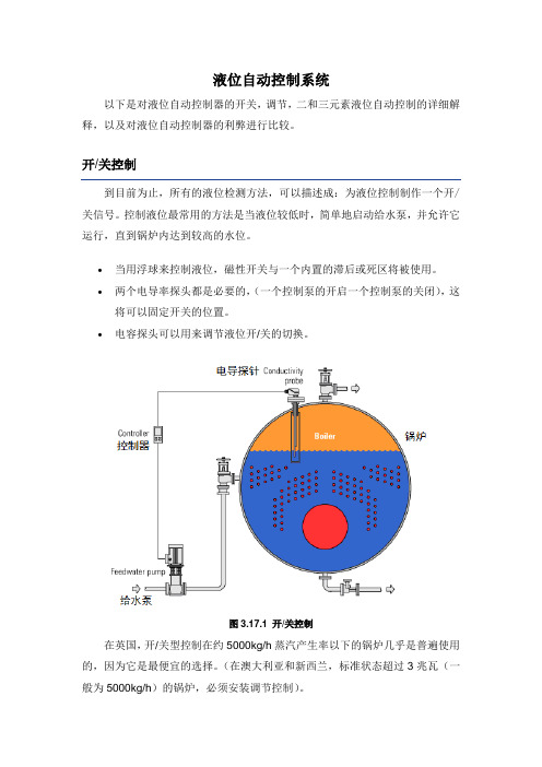
液位自动控制系统以下是对液位自动控制器的开关,调节,二和三元素液位自动控制的详细解释,以及对液位自动控制器的利弊进行比较。
到目前为止,所有的液位检测方法,可以描述成:为液位控制制作一个开/关信号。
控制液位最常用的方法是当液位较低时,简单地启动给水泵,并允许它运行,直到锅炉内达到较高的水位。
∙当用浮球来控制液位,磁性开关与一个内置的滞后或死区将被使用。
∙两个电导率探头都是必要的,(一个控制泵的开启一个控制泵的关闭),这将可以固定开关的位置。
∙电容探头可以用来调节液位开/关的切换。
图3.17.1 开/关控制在英国,开/关型控制在约5000kg/h蒸汽产生率以下的锅炉几乎是普遍使用的,因为它是最便宜的选择。
(在澳大利亚和新西兰,标准状态超过3兆瓦(一般为5000kg/h)的锅炉,必须安装调节控制)。
然而,我们可以说,用这种类型的开/关对锅炉控制是不理想的,因为当泵正在降低锅炉的压力时,要有相对较高温度的“冷”给水流量。
这将导致燃烧器的发射率不断随泵的切换而关闭。
举一个典型的例子,通过计算表明,即使在80℃的时候给水,燃烧器的发射率可能要比关闭水泵时高出40%。
这种连续变化会导致:∙磨损燃烧控制器∙锅炉的温度不断循环∙降低工作效率∙如题3.17.2所示,是对一个“锯齿”型蒸汽流量图的记录与描绘。
图3.17.2锯齿TRACEON图表记录如果蒸汽负荷高,可变的蒸汽流量,往往会增加水与蒸汽的凝结转换速度,将使液位与相关联的危险低水位锁定越来越不稳定,特别是在多个锅炉安装在一起的时候。
然而,事实上,开/关控制仍然非常广泛的运用于中小型锅炉中,如上述所说的,蒸汽锅炉运行在与负载大波动相关的许多问题中,有一部分是与开/关液位控制系统有关的。
优点:∙简单∙廉价∙对锅炉有很好的支撑缺点:∙每台锅炉都需要有自己的给水泵∙给水泵及控制装置有更多的磨损∙蒸汽压力和流量会变化∙更多的锅炉水被转换凝结∙在日常工作运行中,有较高的大负荷波动的可能性在这种类型的系统中,给水泵连续运行,自动阀门(给水泵和锅炉之间)控制给水流量,并与蒸汽需求相匹配。
外文文献及翻译:基于matlab╲╲dde╲╲simulink╲╲力控的液位控制系统
外文翻译The liquid level control system based ondde\matlab\simulinkProcess control is an important application field of automatic technology, it is to point to the level, temperature, flow control process variables, such as in metallurgy, machinery, chemical, electric power, etc can be widely used. Especially liquid level control technology in real life, played an important role in production, for example, the water supply, civil water tower if low water levels, can affect people's lives in water; Industrial enterprises with water, if the drainage water drainage or controlled properly or not, in relation to the workshop of condition; Boiler drum, if the control level boiler is too low, can make level boiler overheating, possible accident; Jing flow, liquid level control tower control accuracy and level of the craft can influence the quality of the products and the cost, etc. In these production field, are basically labor strength or the operation has certain risk nature of work, extremely prone to accidents caused by operating error, the losses, killing manufacturer. Visible, in actual production, liquid level control accuracy and control effects directly affect the factory production cost and economic benefit of safety coefficient. Even equipment So, in order to ensure safety, convenient operation, you have to research the development of a d v a n c e d l e v e l c o n t r o l m e t h o d s a n d s t r a t e g i e s.The graduation design topic is the liquid level control system based on dde\matlab\simulink\force control, Among them was controlled object for tank level, Communication mode for DDE communications , Matlab is mainly used in the simulation test ,And force control software used for modeling, This system mainly through combination of hardware and software device to achieve precise control of liquid level , In modern industry level control of important component, it influence upon production not allow to ignore, in order to ensure safety in production and the product quality and quantity, the level and perform effective control is very necessary, The following is a description of all aspects:一PID controllerA proportional–integral–derivative controller (PID controller) is a generic .control loop feedback mechanism widely used in industrial control systems.A PID controller attempts to correct the error between a measured process variable and a desired set point by calculating and then outputting a corrective action that can adjust the process accordingly.The PID controller calculation (algorithm) involves three separate parameters; the Proportional, the Integral and Derivative values. The Proportional value determines the reaction to the current error, the Integral determines the reaction based on the sum of recent errors and the Derivative determines the reaction to the rate at which the error has been changing. The weighted sum of these three actions is used to adjust the process via a control element such as the position of a control valve or the power supply of a heating element. By "tuning" the three constants in the PID controller algorithm the PID can provide control action designed for specific process requirements. The response of the controller can be described in terms of the responsiveness of the controller to an error, the degree to which the controller overshoots the set point and the degree of system oscillation. Note that the use of the PID algorithm for control does not guarantee optimal control of the system or system stability.Some applications may require using only one or two modes to provide the appropriate system control. This is achieved by setting the gain of undesired control outputs to zero. A PID controller will be called a PI, PD, P or I controller in the absence of the respective control actions. PI controllers are particularly common, since derivative action is very sensitive to measurement noise, and the absence of an integral value may prevent the system from reaching its target value due to the control action.1.Control loop basicsA familiar example of a control loop is the action taken to keep one's shower water at the ideal temperature, which typically involves the mixing of two process streams, cold and hot water. The person feels the water to estimate its temperature. Based on this measurement they perform a control action: use the cold water tap to adjust the process. The person would repeat this input-output control loop, adjusting the hot water flow until the process temperature stabilized at the desired value.Feeling the water temperature is taking a measurement of the process value or process variable (PV). The desired temperature is called the set point (SP). The outputfrom the controller and input to the process (the tap position) is called the manipulated variable (MV). The difference between the measurement and the set point is the error (e), too hot or too cold and by how much. As a controller, one decides roughly how much to change the tap position (MV) after one determines the temperature (PV), and therefore the error. This first estimate is the equivalent of the proportional action of a PID controller. The integral action of a PID controller can be thought of as gradually adjusting the temperature when it is almost right. Derivative action can be thought of as noticing the water temperature is getting hotter or colder, and how fast, and taking that into account when deciding how to adjust the tap,Making a change that is too large when the error is small is equivalent to a high gain controller and will lead to overshoot. If the controller were to repeatedly make changes that were too large and repeatedly overshoot the target, this control loop would be termed unstable and the output would oscillate around the set point in either a constant, growing, or decaying sinusoid. A human would not do this because we are adaptive controllers, learning from the process history, but PID controllers do not have the ability to learn and must be set up correctly. Selecting the correct gains for effective control is known as tuning the controller.If a controller starts from a stable state at zero error (PV = SP), then further changes by the controller will be in response to changes in other measured or unmeasured inputs to the process that impact on the process, and hence on the PV. Variables that impact on the process other than the MV are known as disturbances and generally controllers are used to reject disturbances and/or implement set point changes. Changes in feed water temperature constitute a disturbance to the shower process.In theory, a controller can be used to control any process which has a measurable output (PV), a known ideal value for that output (SP) and an input to the process (MV) that will affect the relevant PV. Controllers are used in industry to regulate temperature, pressure, flow rate, chemical composition, speed and practically every other variable for which a measurement exists. Automobile cruise control is an example of a process which utilizes automated control.Due to their long history, simplicity, well grounded theory and simple setup and maintenance requirements, PID controllers are the controllers of choice for many of these applications.2.PID controller theoryNote: This section describes the ideal parallel or non-interacting form of the PID controller. For other forms please see the Section "Alternative notation and PID forms".The PID control scheme is named after its three correcting terms, whose sum constitutes the manipulated variable (MV). Hence:where Pout, Iout, and Dout are the contributions to the output from the PID controller from each of the three terms, as defined below.2.1. Proportional termThe proportional term makes a change to the output that is proportional to the current error value. The proportional response can be adjusted by multiplying the error by a constant Kp, called the proportional gain.The proportional term is given by:WherePout: Proportional outputKp: Proportional Gain, a tuning parametere: Error = SP − PVt: Time or instantaneous time (the present)Change of response for varying KpA high proportional gain results in a large change in the output for a given change in the error. If the proportional gain is too high, the system can become unstable (See the section on Loop Tuning). In contrast, a small gain results in a small output response to a large input error, and a less responsive (or sensitive) controller. If the proportional gain is too low, the control action may be too small when responding to system disturbances.In the absence of disturbances, pure proportional control will not settle at its target value, but will retain a steady state error that is a function of the proportional gain and the process gain. Despite the steady-state offset, both tuning theory and industrial practice indicate that it is the proportional term that should contribute the bulk of the output change.2.2.Integral termThe contribution from the integral term is proportional to both the magnitude of the error and the duration of the error. Summing the instantaneous error over time(integrating the error) gives the accumulated offset that should have been corrected previously. The accumulated error is then multiplied by the integral gain and added to the controller output. The magnitude of the contribution of the integral term to the overall control action is determined by the integral gain, Ki.The integral term is given by:Iout: Integral outputKi: Integral Gain, a tuning parametere: Error = SP − PVτ: Time in the past contributing to the integral responseThe integral term (when added to the proportional term) accelerates the movement of the process towards set point and eliminates the residual steady-state error that occurs with a proportional only controller. However, since the integral term is responding to accumulated errors from the past, it can cause the present value to overshoot the set point value (cross over the set point and then create a deviation in the other direction). For further notes regarding integral gain tuning and controller stability, see the section on loop tuning.2.3 Derivative termThe rate of change of the process error is calculated by determining the slope of the error over time (i.e. its first derivative with respect to time) and multiplying this rate of change by the derivative gain Kd. The magnitude of the contribution of the derivative term to the overall control action is termed the derivative gain, Kd.The derivative term is given by:Dout: Derivative outputKd: Derivative Gain, a tuning parametere: Error = SP − PVt: Time or instantaneous time (the present)The derivative term slows the rate of change of the controller output and this effect is most noticeable close to the controller setpoint. Hence, derivative control is used to reduce the magnitude of the overshoot produced by the integral component and improve the combined controller-process stability. However, differentiation of asignal amplifies noise and thus this term in the controller is highly sensitive to noise in the error term, and can cause a process to become unstable if the noise and the derivative gain are sufficiently large.2.4 SummaryThe output from the three terms, the proportional, the integral and the derivative terms are summed to calculate the output of the PID controller. Defining u(t) as the controller output, the final form of the PID algorithm is:and the tuning parameters areKp: Proportional Gain - Larger Kp typically means faster response since thelarger the error, the larger the Proportional term compensation. An excessively large proportional gain will lead to process instability and oscillation.Ki: Integral Gain - Larger Ki implies steady state errors are eliminated quicker. The trade-off is larger overshoot: any negative error integrated during transient response must be integrated away by positive error before we reach steady state.Kd: Derivative Gain - Larger Kd decreases overshoot, but slows down transient response and may lead to instability due to signal noise amplification in the differentiation of the error.二Matlab IntroductionThe MATLAB® environment is well suited to rapid prototyping and application development. The interactive programming environment, built-in math functions, toolboxes, editing and debugging tools, and deployment options all contribute to reducing your overall development time.By using the built-in math functions and the many specialized functions contained within our toolboxes, MATLAB can significantly reduce the time it takes you to develop prototypes. In addition to integrated editing and debugging tools, MATLAB provides a performance profiler to help you further optimize your code when programming in MATLAB.Building applications around complex algorithms and graphics is easier than ever with the GUI builder, GUIDE. GUIDE was redesigned in MATLAB 6 to save you time. It offers all the drag and drop interface options you would expect, such as textboxes, radio buttons, check boxes, listboxes, sliders, pop-up menus, frames and more.When you're ready to deploy your application, the MathWorks offers a number of different options that allow you to either convert or interface your MATLAB application to other environments including C/C++ and the Web. MATLAB is the most productive development environment for creating scientific and engineering applications because it offers powerful tools for every step in the process to reduce your overall development time.MATLAB is a high-performance language for technical computing. It integrates computation, visualization, and programming in an easy-to-use environment where problems and solutions are expressed in familiar mathematical notation. Typical uses include• Math and computation• Algorithm development• Data acquisition• Modeling, simulation, and prototyping• Data analysis, exploration, and visualization• Scientific and engineering graphics• Application development, including graphical user interface building三DDE IntroductionDynamic data exchange (DDE, Dynamic data exchange) is real-time exchange data between applications, it is the effective method between different applications to share data a agreement. DDE agreement is a kind of open, and language unrelated, based on protocol, it allows multiple applications to any human agreed format data exchange or command. It is application through Shared memory process of the communication between a form, also need not user intervention of good data exchange method.DDE applications can be divided into four types: client and server and client/server and the monitor. Conversation is a basic concept of DDE. DDE conversation happened in client applications and server application between. Customer is responsible for initializing and attendant session and control conversation flow, from the server application request data or services; The server application response client applications of data or service request. Client/server applications is both client applications and server application request, it can be and can provideinformation. Monitor application for debugging purposes. DDE applications can have multiple burst conversation, a service applications can also have multiple client applications, a client applications can to multiple requests data service applications, and an application can also act as client applications and services applications, when don't need the service application data or service, the customer will terminate session. DDE agreement must be synchronous control the news session, but in different application can switch between asynchronous session.DDE Application using the three layer identification system: Application name apply), theme name (from) and project name (Item). Application name (also called service name) is located at the top of the hierarchical structure, the service application registration for pointed out that particular DDE server application name, customer the application wants to establish session with the server application must be specified application name when this string marks; Name in every conversation topics is one and to identify logical data connection string, is the total classification, data it defines a server application conversation theme content, the server application can support one or more theme name; Project name identifies exchange unit of data string, furthermore confirm the conversation of detailed information, every theme name may have one or more project name. Example: for a database interface applications, will it supports database name as a theme name, and will all sorts of SQL commands as project name, because the server application can support one or more theme, and each theme name name may have one or more project name; So, when to change or reconstruct a conversation, just changing the subject name or project name can.四force control IntroductionForce control is Beijing SANWEI force control technology and "soft" control strategy software, real-time database and its management system, Web portal of tools and other products. These products are not isolated, and the force control is an application scale can free the system structure, the whole expansion force control system and its various products are made from some components procedures according to certain combinations and become. So this guide is not specifically targeted specific products separately describes the use of method, but the common use of all products introduced method. Force control configuration software is a can run on Windows 98/2000 / NT environment, and can run on Windows CE, DOS embedded environment control fu- nctions such as software modules. It USES function diagram way for users provide interface, possess and real-time database, graphical interface system and communication function.Force charged with monitoring configuration software is to the field production data acquisition and process control of specialized software, the biggest characteristic is to flexible "configuration mode" instead of programming approach to system integration, and it provides a good user interface and simple engineering development, as long as the realization method of software module of pre-settings simple "configuration", it can easily realization and complete monitoring layer each function, shorten the automation engineer system integration time, greatly improve the efficiency of integration.Force charged with monitoring configuration software is in the automatic control system monitoring layer level software platform, it can also and the domestic and foreign various industrial control network communication equipment manufacturer, it is ok with high reliable industrial controlling computer and network system integration, can achieve the purpose of the centralized management and monitoring, and can also be convenient to control layer and management for software and hardware to implement all the interface, with "third party" hardware and software systems for integration.The control strategy in the force control, an application in generator may have a lot of control strategy, but only one main strategy. The Lord, the Lord was first execution strategy calls. Other strategies strategy Strategy nested grade 4, namely for most 0 ~ 3 level, in this category 4, grade 3 0 level supreme, the lowest. Senior strategy can call low-level strategy, and low-level strategy can't call senior strategy. In addition to tier 3 most can have 127 strategy outside, other three grades maximum respectively are 255 strategy. Control strategy of by some basic function blocks, a function blocks represent an operation, algorithm or variables. Function blocks basic execution element is strategy, similar to an integrated circuit blocks, have several input and output, each input and output tube feet all have the only name.Force control control strategy is in control strategy, edited generated generators in automatic control strategy for strategies when inventory compiled, and check grammar mistakes, compile can also manually. Control strategy, and you can also call between if A strategy was B strategy calls, says A is B son strategy. A functional block can be repeated calls, each calls are automa- tically entitled to a name by. The executive order and function block in the position of screen on the upper left, position relevant function block, according to priority execution left after the first order under implementation.Force control control strategy of basic function blocks generator was divided into five categories: variable function blocks, mathematical operation function blocks, program control function blocks, logic function blocks function block and control algorithm.基于matlab\dde\simulink\力控的液位控制系统过程控制是自动技术的重要应用领域,它是指对液位、温度、流量等过程变量进行控制,在冶金、机械、化工、电力等方面得到了广泛应用。
液位控制论文
液位自动控制论文:班级:专业:学号:液位自动控制系统摘要:本文从液位传感器构成原理的分析出发,详细研究了液位继电器在给排水自动控制中的典型应用,并对液位继电器的技术性能进行了量化分析,从理论上推导出各种不同水质情况下,液位继电器测量(检测)适用的距离范围。
关键词:液位检测;给排水;自动控制中图分类号:文献标识码:文章编号:For Draining Water Automatic Control Application Research Sun Ping、Lin Chenfei、Chen Guolei、Lin Yahong、Fang Liya (Zhejiang Water conservancy and Hydropower College,Hangzhou 310018 China)Abstract:This article embarks from the fluid position sensor constitution principle analysis,gives deep insight into the typical application of fluid position relay in the draining water automatic control. It carries on a quantification analysis of the fluid position relay technical performance,theoretically infers the suitable distance scope of fluid position relay measurement (examination) in each different water quality situation.Key words: Fluid position examination, For draining water, Automatic control供水和排水的液位自动控制的方法很多,从控制思想讨论,有开关量的动态液位控制和模拟量的恒值液位控制,前者是将液位控制在一定的变化范围内,后者是用PID调节算法,将液位始终保持几乎恒定状态。
基于单片机的水位控制系统外文翻译

译文:水位检测设计中国水之源总量居世界第六位,人均占有水资源量仅为世界人均占有量旳四分之一,并且在地区上分布很不平衡,长江以北旳广大地区,尤其是北方大、中都市大部分地区处在缺水状态,水资源短缺已成为制约我国经济发展旳一种重要原因。
合理旳运用水资源已成为我国目前面临旳一种重要问题。
为了到达水资源旳合理运用,除了要在兴修水利工程和提高全民节水意识等方面努力提高。
而更重要旳是应用新旳技术信息,实时精确旳理解和掌握多种水情信息,以此根据做出对旳旳水资源调度和管理,做到防患于未然,尽量减少水资源旳挥霍。
再加上长期以来水情水位测量一直是水文、水利部门旳重要课题。
为及时发现事故苗头,防患于未来,经济实用、可靠旳水位无线监测系统将会发挥巨大旳作用。
水位是水库大坝安全、水利排灌调度、蓄水、泄洪旳重要参数之一。
水位旳自动化监测、传播和处理为水库现代化建设提供了良好旳基础资料。
在工农业生产旳许多领域都需要对水位进行监控。
在现场也许无法靠近或无需人力来监控时,我们就可以通过远程监控,坐在监控室里对着有关旳仪器就能对现场进行监控,既以便又节省人力。
为了保证水利发电站旳安全生产,提高发电效率,水电站生产过程需要对水库水位、拦污栅压差和尾水位进行监测。
不过,由于不一样电站有着不一样旳实际状况,因此就有着不一样旳技术规定,并且水位参数旳测量措施和测量位置不一样,对监测设备旳规定亦有所不一样。
这样往往导致监测系统设备专用化程度高,品种多,互换性差,不利于设备维护,亦增长了设备设计、生产、安装旳复杂性。
因此,在综合研究水电站水位监测旳实际状况以及特点旳基础上,运用现代电子技术,尤其是单片机技术和不挥发存储器技术,设计开发一种通用性好,可靠性高,维护以便,可合用于多种监测环境旳多模式水位自动监测系统具有重要旳实际意义。
本课题根据水库旳水位测量需要,设计远程单片机水位监测系统,系统具有水位旳自动检测、定期处理、数据GPRS远程上传等功能。
外文翻译---水塔水位控制系统的研究与设计
外文翻译---水塔水位控制系统的研究与设计外文资料翻译Water Tower Water Level Control System Research And DesignAbstract: The water tower is a water level control system for residential quarters of China's extensive use of the water supply system, the existence of the traditional control methods to control the accuracy of the low power consumption of the shortcomings of large, research-based PLC controlled multi-pump cycle frequency constant pressure water supply system, using programmable logic controller, inverter, as well as devices such as pressure transmitter, complete logic control, speed control and data sampling frequency and other functions, allowing the system to achieve automatic control, to achieve the purpose of energy conservation, improve the quality of the water supply system.Key words: PLC, inverter,constant pressure water supply0 IntroductionWater tower water level control system is the wider use of residential quarters of China's water supply system, water supply systems in most of the traditional use of water towers, water tanks, or high pressure tank pressurization equipment to pump water higher than the actual height of the head to "upgrade" of water, the the result of increased water pump shaft power and energy consumption. Research and design of the towers is the water level control system uses a [1] constant pressure water supply system, stepless speed pumps. Automatically based on changes in water-conditioning system operating parameters to maintain a constant pressure to meet the water requirements of today's advanced, energy-saving and reasonable water supply system [1]. Pump started, pid controller pressure transmitter to the control point to provide the pressure signal, when the pressure point is not equal to set value, pid controller by adjusting the inverter output frequency to change the pump speed to regulate the pipeline pressure constitutes a closed-loop feedback control system, water pressure regulator so that users timely, small fluctuations in results. And in the process control system designed to take full account of the principle of load balancing, to take "first-in-first out" strategy of lining up, the way the implementation of the rotating frequency to ensure that the basic balance of the water usage.1 Frequency Control Constant Pressure Water SupplyPrincipleFrequency Control Constant Pressure Water Supply System by the programmable logic controller (plc), converter (built-pid), pressure transmitter, low-voltage electrical and pump components, such as Figure1. Map m1 ~ m3 for water pump motors, p1 ~ p3 for pumps, km1 ~ km6 for motor starting and stopping each of the AC contactor switch. Basic working principle of the system: by the plc a signal to the inverter to control the water cycle work, when the large volume of water consumed by the plc control of all water line installed in the outlet pipe of the pressure transmitter, pressure standard signals into dc 0 v ~ 10 v into the analog signal converter with pid regulator, pressure settings and pressure feedback values after the implementation of pid calculated values of the output of a frequency converter to set the value for the pump by the inverter to provide variable frequency electrical power to realize stepless speed regulation of electric pumps to regulate the exit of the water supply pipe network pressure, constant pressure water supply to achieve the purpose. Pressure feedback signal in order to ensure an accurate value, yet the value of feedback signal to set the filter time constant. The scope of the power converter, Figure 1 can increase the number of the motor to achieve "a multi-trailers," Optimization of the program.2 towers of water level control system designFrequency according to the principle of constant pressure water supply system the design water level control system of the water tower block diagram shown in Figure 2, the city water network eq with the water level controller to control the injection valve yv1, as long as the water level below the high water mark, then to the pool water automatically. Pool of high / low water level signal directly to the plc, as a high / low level alarm. In order to ensure continuity of supply, the water level of the smaller distance between the upper and lower limits. Domestic water and fire water pump three shared [3], usually yv2 solenoid valve in a state of loss, the closure of the fire pipe network, when a fire occurs, the solenoid valve was yv2 electricity, water distribution network with the closure of life, three water pumps for fire use, and maintain high-pressure fire water value. After the lifting of the fire, three use domestic water pump replaced and the cycle of operation, to maintain constant low water value. Each pump motor can run frequency, and frequency can be run. When the small volume of water consumed, a water pump under the control of the converter stable operation of large quantities of water to the pump when running at full speed there is no guarantee that the pressure on network stability, plc pressure given the lower limit of the inverter signal and high-speed signal at the same time plc was detected, plc automatically work in the original state of the pump frequency into frequency operation, in order to maintain the continuity of pressure at the same time use the next pump put into operation after start-up converter in order to increase the supply pipe network pressure of water to ensure stability; if running two pumps can not meet the requirements of the pressure, the frequency of work will be followed by a state into the pump-frequency operation, and then pump into a variable frequency operation; when the water consumption reduction, the first performanceinverter has been working effectively at the lowest speed signals, when the pressure signal, such as the ceiling is still there, plc will be the first first run of the pump frequency to quit in order to reduce the volume of water supplied, when the two signals when there are still, plc and then quit second frequency of the pump to run until a constant pressure water supply pump with frequency converter. All pump motors start from a stop to and from the start to stop by the inverter to control to achieve soft-start with set, to avoid the start of high-current impact to the pump motor to extend the life of the motor. At the same time, the use of variable frequency operation of the system pumps water cycle in order to "first to open the first gate" of the order of related pumps, so that both the water supply system to ensure back-up water pumps, water pumps and the system have the same running time as effective in preventing back-up pump death occurred not long-term phenomenon of rust and improve the comprehensive utilization rate of equipment, reducing maintenance costs.Electrical control system main circuit see Figure 3. AC contactor km1, km3, km5 were three pump motor control m1, m2, m3 frequency operation; AC contactor km2, km4, km6 respectively control m1, m2, m3 of Frequency operation; fr1, fr2, fr3 thermal relay for protection of the three pump motor overload; qs1, qs2, qs3, qs4 respectively, and three pump motor inverter main circuit isolation switch; fu1 ~ fu3 mainly The fuse circuit. The system works in manual mode, plc alarm detection only by the artificial adoption of panel buttons and switches From water pumps to stop and switch; the system works in automatic mode, all controlled by the plc completed report to the police.3 towers of water level control system software designThe main function of the automatic control system is achieved through software in light of the foregoing [1] control constant pressure water supply system requirements, water towers of the main process control system shown in Figure 4. Use of the timer interrupt function of the realization of pid control regular sampling and output control, three pumps to generate switching signals, the signal contacts of the integrated logic control and alarm handling by the program. In program design to take full account of the principle of load balancing, to take "first-in-first out" strategy of lining up, the way the implementation of the rotating frequency to ensure that the basic balance of the water usage. Constant pressure of life and fire of the two pairs of constant digital value is used directly in the proceedings set. Life when the water supply system for the full-scale settings of 70%, when the fire water supply system for the full-scale settings of 90%. Pid loop gain and time constant is initially set at: gain kc = 0.25, sampling time ts = 0.2 s, integration time ti = 30 min. in accordance with specific conditions need to be further adjusted in order to achieve optimal control.To a constant water supply, landing in the water pressure to increase the inverter output frequency, when the maximum frequency converter and a constant pressure pump can not meet the requirements, while running the pump frequency to switch to the running frequency, At the same time need to start asecond frequency or third pump until the water supply to meet the requirements. Need to determine criteria for the launch of a new water pump is the inverter output frequency is set to reach the upper limit. In order to determine the frequency of the inverter limits the accuracy of least squares by chance should be the frequency of the frequency of fluctuations in the ceiling from the situation. Inverter control motor pumps are activated each time the soft-start, and requires the use of water pumps must turn to serve as a continuous variable frequency pump operation shall not exceed 3 h, each time when the need to launch a new water pump, the pump will run from the existing removal of the inverter, and replace the power-frequency operation, reset the inverter and run the pump for a new start. Three pumps to control the duty cycle is the use of pump No. 1 way to achieve (to 3 in the plus 1 equal to zero), or combined with the total number of pump pump pump rotation to achieve its work.4 Concluding remarksIn this paper, the design of the towers the water level control system uses a programmable logic controller, inverter based on changes in water pressure transmitter through the pid to realize stepless speed variable frequency drive pump motor in the water changes to maintain constant water pressure meet the water requirements, so as to achieve the purpose of constant pressure water supply. In the process control system designed to take full account of the principle of load balancing, to take "first-in-first out" strategy of lining up, the way the implementation of the rotating frequency to ensure that the basic balance of the water usage. Frequency Constant Pressure Water Supply to change the supply of the previous quantitative methods to achieve "DAMA" principle, constant pressure water supply frequency mode thus saving energy, easy to operate, high degree of automation.水塔水位控制系统的研究与设计摘要:水塔水位控制系统是我国住宅小区广泛应用的供水系统,传统的控制方式存在控制精度低、能耗大的缺点,研究设计的基于PLC控制的多泵循环变频恒压供水系统,采用可编程序控制器、变频器以及压力变送器等器件,完成逻辑控制、变频调速和数据采样等功能,使系统实现自动控制,达到节能的目的,提高了供水系统的质量。
毕业设计论文液位控制系统
毕业设计论文液位控制系统Newly compiled on November 23, 2020毕业设计基于S7-300的单容水箱液位控制系统设计Design of Liquid-Level Control System Based on S7-300 专业班级:自动化0x0x班学生姓名: x x x指导教师: x x x 副教授学院:自动化与电气工程学院2016年 6月摘要可编程逻辑控制器(PLC)作为现代工业自动化的三大支柱之一,以其可靠性、灵活性在工业控制领域得到了迅猛的发展。
PLC是微电子技术和自动控制技术相结合的产物,并受到计算机技术、通信技术的影响。
我国近年来工业自动化水平逐渐提高,PLC在许多行业得到了越来越广泛的应用。
西门子公司的S7-300系列PLC以结构紧凑,扩展能力强,高性价比的特点在许多行业受到青睐。
在本次设计中,就以S7-300作为控制器,设计一个运行稳定、安全可靠又经济的液位控制系统。
控制核心以S7-300系列的CPU313C-2DP为主,以电磁阀、压力变送器、水泵、上位机、分隔式水槽等为辅构成了单容水箱液位控制系统,对整个液位控制系统进行了硬件设计和软件设计。
在设计过程中,首先,进行硬件的选择、设计。
其次,针对S7-300PLC的进行模块化编程,实现数据的归一化等功能。
最后,利用组态王软件设计人机对话界面,通过上位机控制实现液位的自动控制,上下限参数的在线设置,及液位测量值的在线监控;达到液位控制系统的技术要求。
关键词:S7-300;组态王;液位控制ABSTRACTProgrammable Logic Controller (PLC), one of the three pillars of modern industry automation, has gained rapidly development at the industry control field for its high reliability and flexibility. PLC is the product of the combination of microelectronic technology and automatic control technology, and it can be influenced by computer technology and communication technology. Recent years, as the level of the industry automation increased in our country, PLC has been widely used in more and more fields. Siemens PLC of the s7-300 series has been the favor of many industries, with the characters of compacted structure, strong extensible ability, and high function/price ratio.This design is going to fulfill a liquid level control system, which is stable, safe, and affordable, using s7-300 as the controller. The core is CPU313C-2DP of S7-300 series and the auxiliary parts contain a solenoid valve, a pressure transmitter, a motor, PC, a separated-type tank and so on. In the design, software system and hardware system can be designed completely.During the designing process, first of all, hardwires are chosen and designed. Second, module programming can be done to get normalized data and Position Control. Third, HMI can be finished using King software, which is used to control the liquid level, adjust the top and bottom limitation parameters on-line, monitor measured value of the liquid level, and meet the technical needs of controlling liquid level.Key Word: S7-300;Kingview;Liquid level目录1 引言课题的提出过程控制通常是指连续生产过程的自动控制,是自动化技术最重要的组成部分之一。
液位自动控制系统的研究_毕业设计论文1 推荐
液位自动控制系统的研究摘要水位控制系统设计是模拟工业生产过程中对水位、流量参数进行测量、控制、观察其变化特性,研究过程控制规律的课题,它主要研究过程控制中动态过程的一般特点——大惯性、大时延、非线性,难以对其进行精确控制,从而使其成为控制理论与控制工程、过程控制教学、试验和研究的理想对象。
本课题首先对水位控制系统做了整体的分析并简单介绍了水位控制系统的控制平台;然后详细介绍了PLC可编程控制器并详细分析了基于PLC的PID控制和串级PID控制,对串级控制系统的特点和主副回路设计进行了详述,设计了双容水箱串级水位控制系统,并根据4:1衰减曲线法对PID参数进行整定;最后根据理论分析进行水位控制系统实验,实验结果表明系统具有优良的控制精度和稳定性。
关键词:水位自动控制系统,PLC技术,PID控制,串级控制The Research of The Water Level Automatic Control SystemAbstractThe water level control system design is a topic, which allows study of the principles of process control as the process variables, for example the level and flux, to be measured, controlled and observed for its variability during the simulation process of modem industrial manufacture. It has the common characteristic of dynamic process in process control such as great inertia, larger delay, nonlinear and difficult to be controlled precisely, so that it becomes a perfect object in the field of control theory and control engineering, process control teaching, testing and study.This topic first has made the whole analysis to the water level control system and simply introduces the water level system control platform, then introduces the PLC programmable controller in detail and amply analyses the PID control and the cascade PID control which based on PLC.It introduces the cascade control system characteristic and the host vice-return route design in detail. The two-tank water level cascade control system has been designed. Then it carries on the PID parameter by 4:1 decay curve law; finally the water control system experiment has been done by the theoretical analysis.The experimental result indicates the system has the fine control precision and the stability.Key words: water level control system, PLC, PID control, cascade control目录摘要 (I)ABSTRACT (II)1 绪论 (1)1.1引言 (1)1.2水位控制当前的研究动态 (1)1.3PID调节器概述 (2)1.3.1PID控制特点 (2)1.3.2PID 控制中尚需解决的问题 (3)1.4本文的主要工作 (4)2 水位控制系统的整体分析 (5)2.1水位控制系统的整体设计 (5)2.2控制平台介绍 (5)2.2.1电源控制屏 (5)2.2.2交流变频调速器 (6)2.3被控对象介绍 (7)3 可编程序控制器PLC 概述 (8)3.1PLC的基本结构 (8)3.1.1 CPU 模块 (8)3.1.2 I/O 模块 (9)3.1.3 编程装置 (9)3.1.4电源 (10)3.2西门子S7-200PLC简介 (10)3.2.1 西门子 S7-200 PLC 的功能概述 (10)3.2.2 西门子 S7-200 PLC 的特点 (11)3.2.3 西门子 S7-200 PLC 的硬件结构 (11)3.2.4 西门子 S7-200 PLC 的工作原理 (12)3.3西门子S7-200PLC的编程语言 (14)3.4S TEP 7-M ICRO/WIN编程软件简介 (15)3.5西门子S7-200PLC的程序结构 (15)4 PID控制器的设计 (16)4.1PID算法概述 (16)4.2 串级控制系统 (18)4.2.1 串级控制系统的特点 (18)4.2.2 串级控制系统的设计 (19)4.3基于PLC的串级控制 (19)4.3.1控制系统框架 (19)4.3.2串级系统的参数整定 (21)5 控制结果 (22)5.1控制软件简介 (22)5.1.1控制界面 (22)5.1.2 控制软件的主要功能 (22)5.2实验结果及分析 (23)结束语 (26)致谢 (27)参考文献 (28)附录A(英文文献) (30)附录B(中文译文) (36)1 绪论1.1引言随着现代工业的进步,水位控制技术迅速发展,但与国外相比仍有很大的差距,当国内还在对水利采取笨拙的排水、泄水方式时,国外便开始通过先进的测控设备,对水利资源进行合理的疏导。
外文翻译---液位检测
附录CLiquidLevelMeasurementChemical industry with the progress of science and technology got rapid development, in order to make the equipment safe and reliable operation, and can be utmost to improve product quantity and quality, to effectively operate automatically and process adjustment, realize the scientific management for the enterprise to provide the necessary material and energy of accurate data, must be in production in the process of pressure, flow, level, temperature, chemical composition of various parameters such as timely, accurate measurement.Generally the process of containers, tanks, towers, tank of liquid surface position level, slot bucket, cans, and warehouse ChuFa solid block, the accumulation of particles, powder height and surface position is called a material level; Two not fluid boundary between the height and the liquid and solid separation height is called interface position, the position of assembly level, material level, liquid level interface.Material level measurement to correctly measure the container storage capacity or quality, know container level of high and low and adjust at any time, in the material level to maintain the required height.Material level measurement in chemical process, not only under normal temperature, atmospheric pressure and ordinary medium, material level, liquid level measurement of the interface, but also often meet high temperature, low temperature, high pressure, inflammable and explosive (negative temperature). Viscosity and foam, boiling dielectric material level measurement problems.In order to adapt to the characteristics of chemical objects, to meet the requirements of the chemical process material level measurement, there are many material level measurement and instrumentation.1. Ultrasonic liquid level meter and radar material level meter(1) ultrasonic liquid level meterMaterial level measurement process, the ultrasonic signal, issued by the ultrasonic probe, the liquid or solid material surface after launch back, by the same sensor receiving, ultrasonic measurement of the whole running time, so as to realize the measurement of material level,acoustic velocity transmission of the ultrasonic pulse, from transmitting to receiving to ultrasonic pulse need time interval and the transducer to the surface of the measured medium is proportional to the distance.Emit ultrasonic level meter pulse, not the echo of detection at the same time. Due to the launch of the ultrasonic pulse width has a certain time, and after launch the ultrasonic sensor and aftershocks, during cannot detect the echo, so from the start down the surface of the probe a short distance can't normal inspection, this distance is called blind spots. Was the highest level such as into the blind area, detect instrument will not be able to correctly, there will be error, if necessary, heightened level meter can be installed.Ultrasonic liquid level meter also has shortcomings, the ultrasonic transmission by gas interference, level surface bubbles, corrugated, etc, the ultrasonic transmission by gas interference, level surface bubbles, corrugated, etc., the ultrasonic reflection effect. Material is volatile, liquid gas entrapment, the container by vibration (e.g., motors) are installed on the container can't use ultrasonic liquid level meter.(2) radar material level meterRadar level gauge USES launch - reflection - receive work mode. Radar level meter antenna emit electromagnetic wave, the wave reflected by the measured object surface, again by the antenna, the electromagnetic wave from transmitting to receiving time is proportional to the distance to the liquid surface. In practice, there are two kinds of radar level gauge means the frequency modulation continuous wave and pulse wave. Liquid level meter adopts frequency modulation wave technology, power consumption is big, the four wire system, should be used in electronic circuit is complicated. And the radar pulse wave technology level gauge, low power consumption, easy to implement essential safety, high precision, wider application scope.Radar level gauge measuring the electromagnetic waves can pass through a vacuum, don't need a transmission medium, is not affected by air, steam, groove volatile fog effect, can be used for such as coarse benzene volatile medium level measurement.Radar level meter can be used for almost all of the liquid level measurement. Electromagnetic wave on the surface level when firing, signal attenuation, when the signal attenuation through the hours, can lead to radar level meter cannot detect enough electromagnetic wave signal, the conductive medium can be a very good reflection ofelectromagnetic wave, the dielectric constant is greater than 1.5 non conductive medium dielectric constant was 1.0 (air) will also be able to guarantee sufficient reflection wave, dielectric constant, the greater the reflection signal. In practice, almost all medium can reflect enough of reflection wave.(3) radar level gauge, ultrasonic liquid level meterUltrasound and radar is the main measuring principle is different, lead to their different application occasions, radar is given that the dielectric constant of the measured substance, which is given that the density of the material being measured, so the low dielectric constant material radar measurements will be effect to sell at a discount greatly, the solid matter in general, push harder, another wave of different means of transmission components, such as ultrasonic wave was launched by the vibration of the piezoelectric material, so it is can be used in higher pressure or negative pressure of the situation, usually only in the atmospheric pressure containers. The radar can be used in the process of high pressure tank. Radar emission Angle is bigger than ultrasound, small containers or elongated don't recommend using non-contact radar, generally recommend a director radar. Finally is the temperature on the accuracy, of course, must be higher than the ultrasonic, radar must use high resolution radar in the tank, without ultrasonic. As for the price, usually ultrasonic, lower than the radar in a wide range of course some ultrasonic price is also high. Such as the range of 6-70 meters, the preferred ultrasonic liquid level meter. Pay attention to the stirring groove, groove wall adhesion can produce interference of the reflected wave, level measurement, the installation is to choose the appropriate installation position, so as to avoid the interference of these factors.Level two categories, including liquid level and material level. Liquid level and liquid level indicator and two continuous level measurement. Liquid level indicator is the level of several fixed position measuring, used in liquid level of upper and lower limit alarm, etc. Continuous level measurement is to measure liquid level continuously, it is widely used in many fields such as petroleum, chemical industry, food processing, have very important significance. For more than 20 kinds of continuous level measurement method for comparative analysis. Glass tube, glass plate, double color water method.Manual gauging glass tube method: this method is using the principle of communicating vessels, level scale read directly from the instructions. Glass plate method: glass which can beinstalled through connectors can also be installed in the container wall openings, and series a few piece of glass to increase the range. Numerical scale read directly from the glass plate level.Double color gauge method: this method using the optical principle, make water shows green, and make the water vapor shows red, which indicate the water level.Artificial gauging method: the method is used for measuring oil tank liquid level. When measuring, the surveyor gauge Surveyor to volume of the oil dipstick into oil, and filed when feet lead contact with the tank bottom oil dipstick. According to the quantity of oil traces on the oil dipstick, read out the oil level height; End according to the quantity of oil dipstick test cream color change to determine the height of the water cushion layer, to determine high oil and high water above 4 methods are artificial measurement method, measurement is simple, the advantages of high reliability, intuitive, and low cost.Blowing method, differential method, HTG blowing method: because of the blow pipe approximation is equal to the fluid column pressure in the static pressure, thus P = rho gH type of rho - liquid density; H - level. So the liquid level is measured by the static pressure P can be H. Strong method suitable for measuring the corrosive gas blowing, have suspended material content in the liquid, and is mainly used in the measurement accuracy is not high.Differential pressure method: the open container or atmospheric vessels, valves and gas phase pressure pipeline saves. Based on the relationship between differential pressure and liquid level Δ P = P2 - P1 = rho gH type: Δ P - positive and negative pressure chamber pressure transmitter; P2 and P1 - led tube pressure; H - level. Differential pressure transmitter will pressure difference transformation for 4 ~ 20 mA dc signal. If the pressure in the measuring range lower limit of the corresponding output signal is greater than or less than 4 mA, are all need to adjust the migration zero migration technology such as spring, is equal to 4 mA. HTG method: this method is applied to differential pressure oil tank liquid level measurement.Buoy method: this method USES the middle maglev barrel with holes as liquid level sensor. Stainless steel casing from buoy hole through the middle, between fixed to the roof and bottom. Liquid level change driven maglev hollow tube (permanent magnet) hides inside can move up and down the casing, and attract the casing of magnet can move up and down the casing wall, secondary instrument | instrument according to the moving magnet volume to calculate the liquid level.Floating ball method: this method is using the lever principle of work. Floating ball with liquid level change and around the axis of rotation, the pointer on the drive shaft rotation, and at the other end of the lever balance weight balance, at the same time indicates the level value on the dial. Floating ball method have ball float within and outside the floating ball type two kinds. Floating ball method is mainly used for high temperature measurement, the viscosity of the liquid level, but the range is smaller.Servo method: this method USES volatile integral circuit, eliminate jitter, prolong life, improve the precision of level measurement. The modern servo liquid meter measuring accuracy is higher, has 40 m range less than the accuracy of 1 mm, and generally has the function of measuring density distribution and average density.Sinking method: the location of the sinking as the change of liquid level change, but the variation is not equal and level variation. Torque tube sinking method: the torque tube core shaft torsional Angle changes, secondary instrument according to the torsional Angle variation to calculate the liquid level above five kinds of methods are using the buoyancy principle to work.Such as R, R, l, is a fixed value, as long as the use of epsilon 1, epsilon 2, CH can calculate the liquid level H. Measurement of conductive liquid capacitance method principle, the formula is slightly. Capacitive liquid level meter price is low, easy to install and can be applied to occasions of high temperature and high pressure. Capacitive liquid level instrument measurements but repetitive accuracy is low, need regular maintenance and calibration again, working life is not very long.This method is especially suitable for the measurement of conductive liquid, sensitive device resistance characteristics, its resistance along with the change of liquid level change, so the resistance value is transmitted to the secondary circuit level. Electrical parameters of the liquid level sensor method to measure the liquid level changes.Magnetostrictive method, ultrasonic method, modulating optical method, microwave method Magnetostrictive method: the method is used for measuring oil tank liquid level has two float, respectively used to detect oil and gas and oil/water interface. Each float in possession of a set of permanent magnets, used to generate a fixed magnetic field. Measurement, level gauge head emit low "enquiry" pulse current, the magnetic field generated from the current conduction down the waveguide. When electric current magnetic field is met, and float a "return" impulse(also called "waveguide distortion" pulse). Ask pulse and the back pulse time lag between the corresponding to the height of the oil-water interface and the interface of oil and gas. Easy to install, magnetostrictive liquid level meter measuring accuracy is high, but the liquid density and temperature changes can lead to a measurement error, float along the outside of the waveguide tube move up and down, are easy to be jammed.Ultrasonic method: antenna (mostly aperture antenna, also has a planar antenna) radiation, after liquid surface reflection is the antenna, and then calculated by the secondary circuit, transmitting and receiving signals of liquid level difference. The liquid level meter adopts triangle wave form of frequency modulation, and through to the transmitting and receiving signal mixing after get the difference between the signal analysis, microwave transmission time, thus calculate the liquid level. Microwave speed by the transmission medium, the influence of temperature, pressure, liquid dielectric constant is small, but the liquid interface fluctuations, on the surface of the dielectric constant of bubbles, liquid medium has a great influence on the microwave reflection signal strength. When the pressure in excess of the prescribed value, the pressure will have a significant impact on level measurement accuracy. For liquid dielectric constant is less than the stipulated value, most of the radar level gauge need to adopt waveguide, but rust, bend waveguide and tilt will affect the accuracy of measurement. Sky high h, for example, to 20 m, guided wave tube and vertical direction Angle alpha just over 0.573 °, is caused by the liquid level Δ h will be more than 1 mm error, thus proved that the tilted Angle alpha (in degrees) is small, Δ h meet:Radar level gauge is particularly suited to high pollution and high viscosity of the product, such as asphalt, etc. Repeat accuracy of radar level gauge measuring is higher, need regular maintenance and calibration, measurement accuracy is higher, but the price is higher, difficult measurement of oil-water interface.Modulating optical method and microwave method is similar, only by phase or frequency modulation of optical signal instead of microwave signal. But light signals are greatly influenced by steam, oil, steam, and the liquid level fluctuation is very sensitive。
- 1、下载文档前请自行甄别文档内容的完整性,平台不提供额外的编辑、内容补充、找答案等附加服务。
- 2、"仅部分预览"的文档,不可在线预览部分如存在完整性等问题,可反馈申请退款(可完整预览的文档不适用该条件!)。
- 3、如文档侵犯您的权益,请联系客服反馈,我们会尽快为您处理(人工客服工作时间:9:00-18:30)。
液位控制系统论文中英文资料对照外文翻译The liquid level control system based ondde\matlab\simulinkProcess control is an important application field of automatic technology, it is to point to the level, temperature, flow control process variables, such as in metallurgy, machinery, chemical, electric power, etc can be widely used. Especially liquid level control technology in real life, played an important role in production, for example, the water supply, civil water tower if low water levels, can affect people's lives in water; Industrial enterprises with water, if the drainage water drainage or controlled properly or not, in relation to the workshop of condition; Boiler drum, if the control level boiler is too low, can make level boiler overheating, possible accident; Jing flow, liquid level control tower control accuracy and level of the craft can influence the quality of the products and the cost, etc. In these production field, are basically labor strength or the operation has certain risk nature of work, extremely prone to accidents caused by operating error, the losses, killing manufacturer. Visible, in actual production, liquid level control accuracy and control effects directly affect the factory production cost and economic benefit of safety coefficient. Even equipment So, in order to ensure safety, convenient operation, you have to research the development of a d v a n c e d l e v e l c o n t r o l m e t h o d s a n d s t r a t e g i e s.The graduation design topic is the liquid level control system based on dde\matlab\simulink\force control, Among them was controlled object for tank level, Communication mode for DDE communications , Matlab is mainly used in the simulation test ,And force control software used for modeling, This system mainly through combination of hardware and software device to achieve precise control of liquid level , In modern industry level control of important component, it influence upon production not allow to ignore, in order to ensure safety in production and the product quality and quantity, the level and perform effective control is very necessary, The following is a description of all aspects:一PID controllerA proportional–integral–derivative controller (PID controller) is a generic .control loop feedback mechanism widely used in industrial control systems.A PID controller attempts to correct the error between a measured process variable and a desired set point by calculating and then outputting a corrective action that can adjust the process accordingly.The PID controller calculation (algorithm) involves three separate parameters; the Proportional, the Integral and Derivative values. The Proportional value determines the reaction to the current error, the Integral determines the reaction based on the sum of recent errors and the Derivative determines the reaction to the rate at which the error has been changing. The weighted sum of these three actions is used to adjust the process via a control element such as the position of a control valve or the power supply of a heating element. By "tuning" the three constants in the PID controller algorithm the PID can provide control action designed for specific process requirements. The response of the controller can be described in terms of the responsiveness of the controller to an error, the degree to which the controller overshoots the set point and the degree of system oscillation. Note that the use of the PID algorithm for control does not guarantee optimal control of the system or system stability.Some applications may require using only one or two modes to provide the appropriate system control. This is achieved by setting the gain of undesired control outputs to zero. A PID controller will be called a PI, PD, P or I controller in the absence of the respective control actions. PI controllers are particularly common, since derivative action is very sensitive to measurement noise, and the absence of an integral value may prevent the system from reaching its target value due to the control action.1.Control loop basicsA familiar example of a control loop is the action taken to keep one's shower water at the ideal temperature, which typically involves the mixing of two process streams, cold and hot water. The person feels the water to estimate its temperature. Based on this measurement they perform a control action: use the cold water tap to adjust the process. The person would repeat this input-output control loop, adjusting the hot water flow until the process temperature stabilized at the desired value.Feeling the water temperature is taking a measurement of the process value or process variable (PV). The desired temperature is called the set point (SP). The output from the controller and input to the process (the tap position) is called the manipulated variable (MV). The difference between the measurement and the set point is the error (e), too hot or too cold and by how much. As a controller, one decides roughly how much to change the tap position (MV) after one determines the temperature (PV), and therefore the error. This first estimate is the equivalent of the proportional action of a PID controller. The integral action of a PID controller can be thought of as gradually adjusting the temperature when it is almost right. Derivative action can be thought of as noticing the water temperature is getting hotter or colder, and how fast, and taking that into account when deciding how to adjust the tap,Making a change that is too large when the error is small is equivalent to a high gain controller and will lead to overshoot. If the controller were to repeatedly make changes that were too large and repeatedly overshoot the target, this control loop would be termed unstable and the output would oscillate around the set point in either a constant, growing, or decaying sinusoid. A human would not do this because we are adaptive controllers, learning from the process history, but PID controllers do not have the ability to learn and must be set up correctly. Selecting the correct gains for effective control is known as tuning the controller.If a controller starts from a stable state at zero error (PV = SP), then further changes by the controller will be in response to changes in other measured or unmeasured inputs to the process that impact on the process, and hence on the PV. Variables that impact on the process other than the MV are known as disturbances and generally controllers are used to reject disturbances and/or implement set point changes. Changes in feed water temperature constitute a disturbance to the shower process.In theory, a controller can be used to control any process which has a measurable output (PV), a known ideal value for that output (SP) and an input to the process (MV) that will affect the relevant PV. Controllers are used in industry to regulate temperature, pressure, flow rate, chemical composition, speed and practically every other variable for which a measurement exists. Automobile cruise control is an example of a process which utilizes automated control.Due to their long history, simplicity, well grounded theory and simple setup and maintenance requirements, PID controllers are the controllers of choice for many ofthese applications.2.PID controller theoryNote: This section describes the ideal parallel or non-interacting form of the PID controller. For other forms please see the Section "Alternative notation and PID forms".The PID control scheme is named after its three correcting terms, whose sum constitutes the manipulated variable (MV). Hence:where Pout, Iout, and Dout are the contributions to the output from the PID controller from each of the three terms, as defined below.2.1. Proportional termThe proportional term makes a change to the output that is proportional to the current error value. The proportional response can be adjusted by multiplying the error by a constant Kp, called the proportional gain.The proportional term is given by:WherePout: Proportional outputKp: Proportional Gain, a tuning parametere: Error = SP − PVt: Time or instantaneous time (the present)Change of response for varying KpA high proportional gain results in a large change in the output for a given change in the error. If the proportional gain is too high, the system can become unstable (See the section on Loop Tuning). In contrast, a small gain results in a small output response to a large input error, and a less responsive (or sensitive) controller. If the proportional gain is too low, the control action may be too small when responding to system disturbances.In the absence of disturbances, pure proportional control will not settle at its target value, but will retain a steady state error that is a function of the proportional gain and the process gain. Despite the steady-state offset, both tuning theory and industrial practice indicate that it is the proportional term that should contribute the bulk of the output change.2.2.Integral termThe contribution from the integral term is proportional to both the magnitude of the error and the duration of the error. Summing the instantaneous error over time (integrating the error) gives the accumulated offset that should have been corrected previously. The accumulated error is then multiplied by the integral gain and added to the controller output. The magnitude of the contribution of the integral term to the overall control action is determined by the integral gain, Ki.The integral term is given by:Iout: Integral outputKi: Integral Gain, a tuning parametere: Error = SP − PVτ: Ti me in the past contributing to the integral responseThe integral term (when added to the proportional term) accelerates the movement of the process towards set point and eliminates the residual steady-state error that occurs with a proportional only controller. However, since the integral term is responding to accumulated errors from the past, it can cause the present value to overshoot the set point value (cross over the set point and then create a deviation in the other direction). For further notes regarding integral gain tuning and controller stability, see the section on loop tuning.2.3 Derivative termThe rate of change of the process error is calculated by determining the slope of the error over time (i.e. its first derivative with respect to time) and multiplying this rate of change by the derivative gain Kd. The magnitude of the contribution of the derivative term to the overall control action is termed the derivative gain, Kd.The derivative term is given by:Dout: Derivative outputKd: Derivative Gain, a tuning parametere: Error = SP − PVt: Time or instantaneous time (the present)The derivative term slows the rate of change of the controller output and this effect is most noticeable close to the controller setpoint. Hence, derivative control isused to reduce the magnitude of the overshoot produced by the integral component and improve the combined controller-process stability. However, differentiation of a signal amplifies noise and thus this term in the controller is highly sensitive to noise in the error term, and can cause a process to become unstable if the noise and the derivative gain are sufficiently large.2.4 SummaryThe output from the three terms, the proportional, the integral and the derivative terms are summed to calculate the output of the PID controller. Defining u(t) as the controller output, the final form of the PID algorithm is:and the tuning parameters areKp: Proportional Gain - Larger Kp typically means faster response since thelarger the error, the larger the Proportional term compensation. An excessively large proportional gain will lead to process instability and oscillation.Ki: Integral Gain - Larger Ki implies steady state errors are eliminated quicker. The trade-off is larger overshoot: any negative error integrated during transient response must be integrated away by positive error before we reach steady state.Kd: Derivative Gain - Larger Kd decreases overshoot, but slows down transient response and may lead to instability due to signal noise amplification in the differentiation of the error.二Matlab IntroductionThe MATLAB® environment is well suited to rapid prototyping and application development. The interactive programming environment, built-in math functions, toolboxes, editing and debugging tools, and deployment options all contribute to reducing your overall development time.By using the built-in math functions and the many specialized functions contained within our toolboxes, MATLAB can significantly reduce the time it takes you to develop prototypes. In addition to integrated editing and debugging tools, MATLAB provides a performance profiler to help you further optimize your code when programming in MATLAB.Building applications around complex algorithms and graphics is easier than everwith the GUI builder, GUIDE. GUIDE was redesigned in MATLAB 6 to save you time. It offers all the drag and drop interface options you would expect, such as text boxes, radio buttons, check boxes, listboxes, sliders, pop-up menus, frames and more.When you're ready to deploy your application, the MathWorks offers a number of different options that allow you to either convert or interface your MATLAB application to other environments including C/C++ and the Web. MATLAB is the most productive development environment for creating scientific and engineering applications because it offers powerful tools for every step in the process to reduce your overall development time.MATLAB is a high-performance language for technical computing. It integrates computation, visualization, and programming in an easy-to-use environment where problems and solutions are expressed in familiar mathematical notation. Typical uses include• Math and computation• Algorithm development• Data acquisition• Modeling, simul ation, and prototyping• Data analysis, exploration, and visualization• Scientific and engineering graphics• Application development, including graphical user interface building三DDE IntroductionDynamic data exchange (DDE, Dynamic data exchange) is real-time exchange data between applications, it is the effective method between different applications to share data a agreement. DDE agreement is a kind of open, and language unrelated, based on protocol, it allows multiple applications to any human agreed format data exchange or command. It is application through Shared memory process of the communication between a form, also need not user intervention of good data exchange method.DDE applications can be divided into four types: client and server and client/server and the monitor. Conversation is a basic concept of DDE. DDE conversation happened in client applications and server application between. Customer is responsible for initializing and attendant session and control conversation flow, from the server application request data or services; The server applicationresponse client applications of data or service request. Client/server applications is both client applications and server application request, it can be and can provide information. Monitor application for debugging purposes. DDE applications can have multiple burst conversation, a service applications can also have multiple client applications, a client applications can to multiple requests data service applications, and an application can also act as client applications and services applications, when don't need the service application data or service, the customer will terminate session. DDE agreement must be synchronous control the news session, but in different application can switch between asynchronous session.DDE Application using the three layer identification system: Application name apply), theme name (from) and project name (Item). Application name (also called service name) is located at the top of the hierarchical structure, the service application registration for pointed out that particular DDE server application name, customer the application wants to establish session with the server application must be specified application name when this string marks; Name in every conversation topics is one and to identify logical data connection string, is the total classification, data it defines a server application conversation theme content, the server application can support one or more theme name; Project name identifies exchange unit of data string, furthermore confirm the conversation of detailed information, every theme name may have one or more project name. Example: for a database interface applications, will it supports database name as a theme name, and will all sorts of SQL commands as project name, because the server application can support one or more theme, and each theme name name may have one or more project name; So, when to change or reconstruct a conversation, just changing the subject name or project name can.四force control IntroductionForce control is Beijing SANWEI force control technology and "soft" control strategy software, real-time database and its management system, Web portal of tools and other products. These products are not isolated, and the force control is an application scale can free the system structure, the whole expansion force control system and its various products are made from some components procedures according to certain combinations and become. So this guide is not specifically targeted specific products separately describes the use of method, but the common use of all products introduced method. Force control configuration software is a can run on Windows 98/2000 / NT environment, and can run on Windows CE, DOSembedded environment control fu- nctions such as software modules. It USES function diagram way for users provide interface, possess and real-time database, graphical interface system and communication function.Force charged with monitoring configuration software is to the field production data acquisition and process control of specialized software, the biggest characteristic is to flexible "configuration mode" instead of programming approach to system integration, and it provides a good user interface and simple engineering development, as long as the realization method of software module of pre-settings simple "configuration", it can easily realization and complete monitoring layer each function, shorten the automation engineer system integration time, greatly improve the efficiency of integration.Force charged with monitoring configuration software is in the automatic control system monitoring layer level software platform, it can also and the domestic and foreign various industrial control network communication equipment manufacturer, it is ok with high reliable industrial controlling computer and network system integration, can achieve the purpose of the centralized management and monitoring, and can also be convenient to control layer and management for software and hardware to implement all the interface, with "third party" hardware and software systems for integration.The control strategy in the force control, an application in generator may have a lot of control strategy, but only one main strategy. The Lord, the Lord was first execution strategy calls. Other strategies strategy Strategy nested grade 4, namely for most 0 ~ 3 level, in this category 4, grade 3 0 level supreme, the lowest. Senior strategy can call low-level strategy, and low-level strategy can't call senior strategy. In addition to tier 3 most can have 127 strategy outside, other three grades maximum respectively are 255 strategy. Control strategy of by some basic function blocks, a function blocks represent an operation, algorithm or variables. Function blocks basic execution element is strategy, similar to an integrated circuit blocks, have several input and output, each input and output tube feet all have the only name.Force control control strategy is in control strategy, edited generated generators in automatic control strategy for strategies when inventory compiled, and check grammar mistakes, compile can also manually. Control strategy, and you can also call between if A strategy was B strategy calls, says A is B son strategy. A functional block can be repeated calls, each calls are automa- tically entitled to a name by. The executive order and function block in the position of screen on the upper left, position relevant function block, according to priority execution left after the first order under implementation.Force control control strategy of basic function blocks generator was divided into five categories: variable function blocks, mathematical operation function blocks, program control function blocks, logic function blocks function block and control algorithm.基于matlab\dde\simulink\力控的液位控制系统过程控制是自动技术的重要应用领域,它是指对液位、温度、流量等过程变量进行控制,在冶金、机械、化工、电力等方面得到了广泛应用。