水力消防炮详解[en]
消防水炮系统
消防水炮系统消防水炮系统是一种用于灭火和控制火灾的重要设备,它能够喷射高压水流,将火势控制在可控范围内,保护人员的生命安全和财产安全。
消防水炮系统的标准格式文本如下:一、系统概述消防水炮系统是一种用于消防灭火的设备,通过连接消防水源和水炮,能够喷射高压水流,迅速灭火。
它由水源供应系统、水泵、管道系统、水炮等组成。
二、系统组成1. 水源供应系统:该系统由水源、水泵和水源管道组成。
水源可以是自来水、水井或者水池等,水泵负责将水源抽送至管道系统,确保水炮能够正常工作。
2. 水泵:水泵是消防水炮系统的核心设备,它负责提供高压水流。
水泵应具备自动启停、自动保护等功能,以确保系统的可靠性和安全性。
3. 管道系统:管道系统由供水管道、回水管道和支管组成。
供水管道将水源供应至水炮,回水管道将用过的水排出,支管用于连接水源供应系统和水炮。
4. 水炮:水炮是消防水炮系统的喷射装置,它能够喷射高压水流,将火势控制在可控范围内。
水炮应具备远程控制、调节喷射角度和喷射距离的功能。
三、系统工作原理1. 水源供应系统将水源供应至水泵,水泵将水源抽送至管道系统。
2. 当发生火灾时,消防人员通过控制系统开启水泵,水泵将水源抽送至管道系统。
3. 高压水流通过管道系统传输至水炮,水炮通过远程控制将水流喷射至火源。
4. 水炮的喷射角度和喷射距离可以根据火势的大小和位置进行调节,以最大程度地控制和灭火。
四、系统要求1. 设备可靠性:消防水炮系统的各个组成部份应具备高可靠性,能够在紧急情况下正常工作,确保灭火效果。
2. 操作简便性:系统操作应简单明了,消防人员能够迅速掌握操作方法,并能够远程控制水炮的喷射角度和喷射距离。
3. 系统安全性:消防水炮系统应具备自动启停、自动保护等功能,能够在异常情况下自动住手工作,确保系统和人员的安全。
4. 喷射性能:水炮的喷射性能应满足灭火要求,包括喷射角度范围、喷射距离和喷射流量等。
五、系统维护1. 定期检查:对消防水炮系统进行定期检查,包括水源供应系统、水泵、管道系统和水炮等各个组成部份,确保其正常工作。
消防水炮使用过程中的优势

说起消防水炮,相比大家印象里首先浮现的是拥有像坦克一般的外观,喷水威力是消防水枪的成倍之大,水压非常高且每次部署都需要好几个人员才能动员使用的,灭火威力巨大但比较笨重。
消防水炮在大多数的人们脑海就是这样一种消防器材设备。
实际上,消防水炮分很多种类型号,并不是所有的型号都像拖车式消防炮那样笨重的。
下面带你进一步深入的了解一下消防炮,并探讨实际灭火应用过程当中,消防水炮相较于其它消防器材给我们带来了哪些优势,好消除以往大家对消防水炮持有灭火威力大但是机动力低较笨重使用不便的错误印象。
消防水炮本身集消防器材火灾识别探测器(初期火势非常小的时候发明)、火灾报警、喷水装置(水量很小5L\S)于一体的主动跟踪定位射流的主动灭火设备。
由于它的体积小、喷水距离远、在高峻的空间(如火车站、机场的候车厅等等)被越来越多的使用。
但是呢,现实当中发生火灾,大概几秒钟的时间里火宛如一下就着大,一下就蔓延开了,而这个灭火的设备呢,它从发明着火部位到定位瞄准着火点,最少要30s的时间,再到联动水泵取水灭火时间就更长了,所有就有些疑惑这么一个主动灭火的设备,在真实发生火灾的时候能否真正的发挥它灭火的作用?着实一样平常来说,主动消防水泡多用来作为自喷的补充和增强。
多作为高峻空间,自喷无法布置或者危害程渡过大自喷无法有用掩护时使用,详细的布置场所可以参见《固定消防灭火体系设计范例》。
一样平常普通场所,少少设置,一是由于消防炮有安装高度要求,大于8米小于40米,二是由于消防炮价格着实相较于其他消防器材来说偏高。
①5L/s这个流量着实是一个很大的流量了。
给个直观的印象,给水体系中,一个当量是0.2L/s,一个当量就是一个单阀水嘴的流量,就是你家里用的自来水龙头开到最大的流量。
5L/s就是25个家里的自来水龙头开到最大的流量。
再讲一个,中危2级自喷的喷淋强度要求是8L/min·m2。
细致单位。
所以说消防炮是自喷的晋级版不是没有来由的。
灭火利器消防水炮的威力与使用方法
灭火利器消防水炮的威力与使用方法消防水炮,作为一种常见且有效的灭火利器,对于火灾的扑灭和控制起到不可替代的重要作用。
本文将深入探讨消防水炮的威力以及其正确的使用方法,以期给读者带来全面而实用的消防知识。
一、消防水炮的威力消防水炮以其强大的水流和喷射距离而闻名,具有以下几个威力显著的特点。
1. 扑救远距离火灾的威力消防水炮的最大特点之一是其远距离扑救火灾的能力。
一般情况下,消防水炮的喷射距离可达数百米,能够将水流准确投射到火灾现场,弥补了消防员在无法靠近火源的情况下进行灭火的局限性,大大提高了扑灭火灾的效率和安全性。
2. 快速冷却和灭火的能力消防水炮的水流强劲,能够快速将火源周围的温度迅速降低,发挥出较强的冷却效果。
同时,在水流撞击下,火灾区域的火焰也会得到有效控制,阻断火势的蔓延,实现火灾的迅速灭火。
3. 对高温物质和燃烧场所的克服能力在一些特殊的火灾场景中,火源往往位于高温物质内部,此时,常规的灭火手段很难发挥作用。
而消防水炮以其大流量、大冲力的特性,能够直接穿透高温物质进行灭火,对于高温物质和高温环境下的火灾有着明显的克服能力,提供了更多选择和保障。
二、消防水炮的使用方法正确的使用方法对于发挥消防水炮的威力至关重要。
以下是一些常见的使用方法,用于指导消防人员在实际灭火工作中正确操作水炮。
1. 确保安全在使用消防水炮之前,要确保周围环境的安全性。
检查周围是否有易燃易爆物质,以免引发二次火灾。
同时,还要保证自己的安全,佩戴好防护装备,避免受伤。
2. 正确瞄准在使用消防水炮时,要准确瞄准火源。
根据火灾的位置和火势大小,选择适当的角度和喷射距离,确保水流能够直击火源并形成较好的湿化效果。
3. 控制水炮喷射使用水炮时应注意控制喷射。
水炮的喷射过程中,水流对火源的冲击力较大,要保持稳定的姿势和力道,以免造成火势扩大或其他不必要的损失。
同时,需要掌握喷射的角度和喷射范围,确保灭火的全面性和效果。
4. 灭火后的处理在成功扑灭火源后,要及时进行善后工作。
消防水炮系统

消防水炮系统消防水炮系统是一种重要的消防设备,用于灭火和控制火势,确保人员安全和财产保护。
本文将详细介绍消防水炮系统的标准格式。
一、引言消防水炮系统是一种重要的消防设备,用于应对火灾和灭火。
它可以通过高压水流将火势控制在一定范围内,确保人员的安全和财产的保护。
本文将介绍消防水炮系统的标准格式,包括系统组成、工作原理、技术要求等。
二、系统组成1. 消防水炮:消防水炮是系统的核心部件,通常由水枪、喷嘴和支架组成。
它能够产生高压水流,用于灭火和控制火势。
2. 水源系统:消防水炮系统需要可靠的水源供应,通常通过消防水泵或者消防水箱提供。
水源系统应保证足够的水压和流量。
3. 控制系统:消防水炮系统需要一个可靠的控制系统,用于控制水炮的方向、角度和水流量。
控制系统通常由控制阀、控制面板和传感器组成。
4. 供电系统:消防水炮系统需要一个稳定的供电系统,以保证各个部件的正常工作。
供电系统应具备过载保护和短路保护功能。
5. 监控系统:消防水炮系统需要一个监控系统,用于实时监测水炮的工作状态和火势情况。
监控系统通常由摄像头、显示器和报警器组成。
三、工作原理1. 消防水炮通过水泵将水源抽取到水炮中,并通过喷嘴形成高压水流。
2. 控制系统可以调节水炮的方向、角度和水流量,以适应不同的灭火需求。
3. 监控系统可以实时监测水炮的工作状态和火势情况,并在需要时发出报警信号。
4. 消防人员可以通过控制系统和监控系统对水炮进行远程操作和监控,确保灭火效果和人员安全。
四、技术要求1. 消防水炮系统应符合国家相关标准和规范的要求。
2. 水炮的射程和射程角度应能够满足实际灭火需求。
3. 水炮的出水口应具备调节水流量和喷雾形状的功能。
4. 控制系统应具备远程操作和监控功能,方便消防人员的使用。
5. 监控系统应具备实时监测和报警功能,以及视频录相和存储功能。
6. 水源系统应具备稳定的水压和流量,以满足消防水炮的工作需求。
7. 供电系统应稳定可靠,具备过载保护和短路保护功能。
消防水炮

消防水炮系统的工作原理是通过前端探测系统采集现场红外图像,中央控制器采用图像处理的手段对发生在控制区域内的火灾进行侦测和定位,打开相应的联动设备并控制水炮进入喷水灭火操作。
系统各部分分布于控制现场不同的位置。
采用红外双波段探测技术在有效探测火源的同时提高抗环境干扰的能力;并可进行地面灵敏度参数设置及调试
通过带有滤光片的双波段火灾探测器得到火灾监控现场实时画面,利用图像探测和图像识别方法对着火物体的火灾特征进行数字计算分析并提取图像中的火灾元素,发现可能引起火灾的火源,一旦火灾元素被提取,系统主机将指挥其消防联动、报警、显示与自动定位等。
自动控制方式:当前端探测器报警后,报警信号传给消防炮中央控制系统,由主机对火灾进行分析判别后,确定着火点,同时,对应着火区域的消防炮自动指向着火点,打开电动阀,向着火点喷水灭火
消防控制中心远程控制方式:当前端探测器报警后,值班人员通过被强制切换过来的彩色画面,通过控制室的中心手动操作盘控制消防炮瞄准着火点,打开电动阀喷水灭火。
现场手动控制:当现场人员发现火灾后,直接通过消防炮现场手动操作盘控制消防炮瞄准着火点,启动消防泵,打开电动阀喷水灭火。
现场手动控制具有优先权。
为防止误操作,中心手动操作盘具有多级安全锁或操作权限设定功能。
消防炮联动功能:水炮接入火灾自动报警系统,除水炮本身可进行火灾探测和自动灭火控制外,还可通过火灾自动报警系统的联动功能对水炮进行联动控制,能对消防炮等系统组件进行单机、联动或自动操作。
控制电动阀门的开启和关闭,并显示其状态。
当接到报警信号后,能立即向消防泵站、消防控制室等有关部门发出报警信号,声光信号可手动解除。
消防水炮.ppt

由联动控制柜及区域控制箱、系统电源控制器、计算机火灾(视频)监 控系统组成。其目的在于对供水系统和执行系统进行控制,可灵活的实 现手动、自动以及现场、消防中心的各种操作。有效完成从发现火灾直 至扑灭火灾等一系列动作。并能使自动跟踪定位射流灭火系统通过输入 模块和输入输出模块直接与火灾自动报警中心连接,保证火灾报警系统 的整体性。
消防水炮
消防水炮是一种直接
连接钢性水管,调整水流, 并由炮头发射水流灭火 的消防器材。 制冷设备中,管壳式水 冷冷凝器的别称。 消防水炮常用于消防
组成部分
供水系统
主要由水源、消防水泵、高位水箱或气压稳压装置、水泵接合器和管路 组成,其目的在于能给装置提供快速的、充足的水源。
执行系统
由灭火装置、电源装置、火灾自动报警装置等中间执行装置组成,即当 发生火情时,执行灭火及报警动作的相关组件。
用途
防暴
一、现代警用脉冲防暴水炮。从上世纪90年代以来,,各国 安全部队打击恐怖主义活动,制止暴乱,维护和平,保证国 家安全和社会稳定的任务越来越艰巨,在任务的催使下,非 致型非致命武器装备,在实战中发挥 了重要作用。
二、车载式防暴水炮利用压缩空气为动力,在极短的时间内 由排气阀排出,推动身管中的刺激剂液体以较高的速度喷出, 空气与液体分子摩擦碰撞产生粒度大约为2~200微米的雾 化颗粒,从空中落到地面约用时3~5秒,在目标区域会形成 一个刺激剂雾团。
用途
消防
消防水炮是消防作战中常用的主要装备之一,可用于 灭火、冷却、隔热和排烟等消防作业。当前消防作 战中使用的常规水炮体积大、后座力大、不便于移 动,导致对火灾的反应能力较差。消防水炮还包括便 携式可折叠移动消防水炮、自动扫描射水高空水炮、 固体消防水炮。
消防水炮
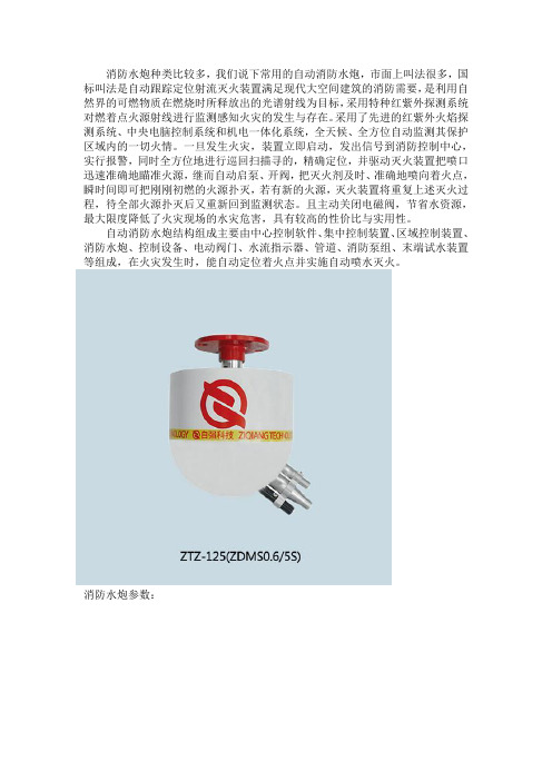
消防水炮种类比较多,我们说下常用的自动消防水炮,市面上叫法很多,国标叫法是自动跟踪定位射流灭火装置满足现代大空间建筑的消防需要,是利用自然界的可燃物质在燃烧时所释放出的光谱射线为目标,采用特种红紫外探测系统对燃着点火源射线进行监测感知火灾的发生与存在。
采用了先进的红紫外火焰探测系统、中央电脑控制系统和机电一体化系统,全天候、全方位自动监测其保护区域内的一切火情。
一旦发生火灾,装置立即启动,发出信号到消防控制中心,实行报警,同时全方位地进行巡回扫描寻的,精确定位,并驱动灭火装置把喷口迅速准确地瞄准火源,继而自动启泵、开阀,把灭火剂及时、准确地喷向着火点,瞬时间即可把刚刚初燃的火源扑灭,若有新的火源,灭火装置将重复上述灭火过程,待全部火源扑灭后又重新回到监测状态。
且主动关闭电磁阀,节省水资源,最大限度降低了火灾现场的水灾危害,具有较高的性价比与实用性。
自动消防水炮结构组成主要由中心控制软件、集中控制装置、区域控制装置、消防水炮、控制设备、电动阀门、水流指示器、管道、消防泵组、末端试水装置等组成,在火灾发生时,能自动定位着火点并实施自动喷水灭火。
消防水炮参数:产品特点:1、可与其他火灾报警系统实现联动2、采用炮载图像技术,实现远程可视化灭火3、可实现自动探测报警并自动定位着火点4、具有自动控制、远程手动控制和现场手动控制功能5、探测距离远,保护面积大,响应速度快,探测灵敏度高6、自动定位,远程定点灭火,减少了扑救过程中造成的损失7、系统可同时具有防火、灭火、监控功能,提高了系统的可靠性产品适用范围:工厂车间、仓储物流展览建筑:会展中心、展览馆等;体育建筑:体育比赛场馆、训练场馆等;康复建筑:大型医院、疗养院、康复中心等;办公建筑:大型办公楼、写字楼、商务大厦等;文化建筑:文化中心、博物馆、图书馆、艺术馆等;商业建筑:大型商场、超级市场、购物中心、室内商业街等;工业建筑:大型工业厂房及库房,生产、贮存A类物品的建筑;排演建筑:歌舞剧院、音乐厅、电影院、礼堂、纪念堂、殡仪馆等;客运建筑:机场、火车站、汽车站、码头等客运站的旅客候机。
消防水炮操作说明
消防炮使用操作说明
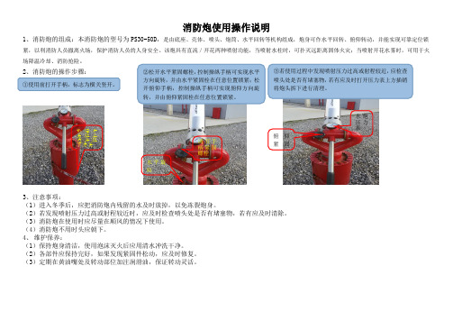
1、消防炮的组成:本消防炮的型号为PS30-50D ,是由底座、壳体、喷头、炮筒、水平回转等机构组成,炮身可作水平回转、俯仰转动,并能实现可靠定位锁紧,以利消防人员撤离火场,保护消防人员的人身安全。
该炮具有直流/开花两种喷射功能,当喷射水柱时,可扑灭远距离固体火灾;当喷射开花水雾时,可用于火场降温冷却、消防抢险。
2、消防炮的操作步骤:
3、注意事项:
(1)进入冬季后,应把消防炮内残留的水及时放掉,以免冻裂炮身。
(2)若发现喷射压力过高或射程较近时,应及时检查喷头处是否有堵塞物,若有应及时清除。
(3)消防炮在使用时应尽量在顺风的情况下使用。
(4)消防炮不用时头应朝下。
4、 维护保养:
(1)保持炮身清洁,使用泡沫灭火后应用清水冲洗干净。
(2)各部件应保持完好,如果发现紧固件松动,应及时修复。
(3)定期在黄油嘴处及转动部位加注润滑油,保证转动灵活。
①使用前打开手柄,标志为横关竖开。
②松开水平紧固螺栓,控制操纵手柄可实现水平方向旋转,并由水平紧固栓在任意位置锁紧;松开俯仰手柄,控制操纵手柄可实现俯仰方向旋
转,并由俯仰紧固栓在任意位置锁紧。
③若使用过程中发现喷射压力过高或射程较近,应检查喷头处是否有堵塞物,若有应及时打开压力表上方插销将炮头拆下进行清理。
水炮开关往上为开往下为关
调节手柄紧固螺栓 水炮压力表 水平旋
转 俯仰紧固。
- 1、下载文档前请自行甄别文档内容的完整性,平台不提供额外的编辑、内容补充、找答案等附加服务。
- 2、"仅部分预览"的文档,不可在线预览部分如存在完整性等问题,可反馈申请退款(可完整预览的文档不适用该条件!)。
- 3、如文档侵犯您的权益,请联系客服反馈,我们会尽快为您处理(人工客服工作时间:9:00-18:30)。
Guideline No.: F-09(201510)F-09 FIRE MONITORIssued date: October 20,2015 © China Classification SocietyForeword:This Guide is a part of CCS Rules, which contains technical requirements, inspection and testing criteria related to classification and statutory survey of marine products.This Guide is published and updated by CCS and can be found through . Comments or suggestions can be sent by email to ps@ .Historical versions and release date :Main changes and effective date:CONTENTS1 Application (4)2 Normative references (4)3 Terms and definitions (4)4Drawings and documentation to be submitted (4)5Design and technical requirements (5)6 Selection of typical test specimens (8)7 Type test (8)8 Unit/batch inspection (11)Fire Monitor1 Application1.1 The Guideline are applicable to the fixed deck foam systems specified in 10.8.1, Chapter II-2 of SOLAS and foam monitors required for helideck fire fighting systems specified in 18.5.3, Chapter II-2 of SOLAS.1.2 This Guideline is applicable to the fire water monitors and foam monitors required for fire fighting ships specified in Chapter 1, PART EIGHT of CCS Rules for Classification of Sea-going Steel Ships.2 Normative references2.1 Regulations 10.8.1 and 18.5.3, Chapter II-2 of SOLAS 1974 and Amendments thereto2.2 Chapter 14 of International Code for Fire Safety Systems2.3 MSC.1/Circ.1431 Guidelines for Inspection of Foam Fire Extinguishing Equipment Used for Helideck Protection2.4 Chapter 1, PART EIGHT of the Rules for Classification of Sea-going Steel Ships2.5 GB19156- 2003 General Specifications for Fire Monitors3 Terms and definitions3.1 Fire monitor: a device spraying fire extinguishing media in the form of jet at a flow rate of the water-foam mixture usually larger than16l/s.3.2 Foam/water dual use fire monitor: a fire monitor using two kinds of fire extinguishing media, namely, water and foam.4 Drawings and documentation to be submitted4.1 For product approval, the following drawings and documentation to be submitted are to be submitted to CCS for product approval:4.1.1 General assembly drawing of the product series;4.1.2 Main properties and specifications table;4.1.3 Summary table of material mechanical and chemical properties of main parts;4.1.4 Technical specifications for acceptance of delivered products;4.1.5 Type test plan.4.2 For product approval, the following drawings and documentation to be submitted are to be submitted to CCS for review:4.2.1 Instructions for use of product;4.2.2 Instructions for maintenance.5 Design and technical requirements5.1 The rated working pressure of fire water monitor, foam monitor and foam/water dual use monitor at various flow rate stages is to comply with the requirements of Table 1, Table 2 and Table 3 respectively. The rated working pressure of fire water monitor, foam monitor and foam/water dual use monitor is allowed to exceed the upper limit values given in Table 1~Table 3, but is not to exceed 1.6MPA (except for the circumstance involving special purposes).5.2 The angles of pitching rotation of fire monitors: minimum depression angle is to be ≤- 30︒ and the maximum depression angle is to be ≥+ 60︒.5.3 The horizontal rotation angle of fire monitors is to be 360︒ when it is manually operated and ≥270º when it is electrically operated.5.4 Fire monitors are to be manufactured with corrosion resistant materials or anti-corrosion treated materials to meet the corrosion protection requirements corresponding to the service environment and agent. The cast parts of fire monitors are to be made of cast aluminum alloy, cast copper alloy or spheroidal graphite cast iron materials, except when there are special requirements.5.5 Appearance5.5.1 The surfaces of forged parts are to be smooth, bright and free from defects affecting the strength and performance of the forged parts, such as crack, porosity, shrinkage cavity, blow hole, etc.5.5.2 Welded seams are to be smooth and even and free from lack of penetration, burn through, beads and other defects detrimental to the strength and appearance quality.5.5.3 The corrosion protective coating on the external surface of fire monitors is to be smooth, clean, even and free from defects affecting appearance quality, such as air voids, apparent flow marks, cracking, etc.5.6 Maneuverability5.6.1 The pitching rotation mechanism, horizontal rotation mechanism and various control levers (wheels) of fire monitors are to be flexible to operate and the transmission mechanism of fire monitors is to be safe and reliable.5.6.2 The pitching and horizontal rotation mechanisms of fire monitors are to be provided with self-locking function or locking arrangements to prevent swaying or sliding when the fire monitors are spraying at the angle set as required.5.7 A pressure gauge having a precision level not less than 2.5 grade is to be fitted at an appropriate location on the surface along the external diameter of the monitor base.5.8 Special requirements5.8.1 Foam monitor used in fixed deck foam system5.8.1.1 Foam monitors are to be capable of spraying the foam onto the entire area of cargo oil tank deck and into any cargo oil tank whose deck has been damaged.5.8.1.2 When the capacity of a foam system is designed, the effective range of foam monitors is to be defined to be 75% of the monitor’s range under static wind conditions.5.8.1.3 One foam monitor is to be provided respectively on both sides of each ship. The greater of the values listed below is to be taken as the design flow rate of each foam monitor:(1) Area of cargo oil tank deck ×0.3 l/min, where the area of cargo oil tank deck means theship’s extreme breadth multiplied by the longitudinal total length of all cargo oil tank spaces;or(2) Area of the horizontal section of a single cargo oil tank having the largest area×3 l/min; or(3) The maximum protection area in front of the foam monitor ×3 l/min;but not less than1250l/min.5.8.1.4 The differences between the actual expansion ratio and drainage time of the foam generated and sprayed by foam monitors and the parameters published by the manufacturer of the foam extinguishing agent are to be within±10%.5.8.1.5 If the foam monitors have any motor-driven mechanism and are installed in hazardous areas where explosive gases are likely to be present, the driving motors are to comply with the electrical explosion protection requirements specified in 1.3.3, Chapter 1, PART FOUR of CCS Rules for Classification of Sea-going Steel Ships.5.8.1.6 Valves are to be installed on the foam main and fire main (if the latter is an integral part of the deck foam system) in front of the foam monitor to provide effective isolation in the event of foam pipe damage.5.8.2 Foam monitors on external fire fighting ships5.8.2.1 Each external fire fighting ship is to be equipped with two foam monitors, with each foam monitor having a flow rate not less than 300m3/h, and the expansion ratio of foam is not to exceed12;5.8.2.2 The spray height of foam monitors is to be at least 50m above the sea surface;5.8.2.3 Foam monitors are to be provided with, in addition to local manual control devices, remote control facilities. The remote control facilities of foam monitors and those of water monitors are to be arranged in the same space.5.8.2.4 Design and bracket of foam monitors(1) Foam monitors are to be of robust construction;(2) The brackets of foam monitors are to have sufficient strength under varying workingconditions.5.8.3 Fire water monitors on external fire fighting ships5.8.3.1 The minimum quantity and properties of water monitors are to comply with the requirements of Table 4.5.8.3.2 Arrangement of water monitors system(1) Water monitors are to be capable of adequately adjusting the angles in vertical andhorizontal directions to ensure optimum point of fall of the water jets. The required operating range is to be free from obstacles obstructing the water jets;(2) Water monitors are to be installed on fixed and secure brackets capable of withstanding theapplied forces under various operating conditions;(3) At least two water monitors are to be fitted with nozzles capable of spraying water jet orwater mist as required.5.8.3.3 In addition to local manual control devices, water monitors are to be provided with remote control facilities. The remote control facilities are to be installed at locations with means of protection and with good vision to allow for observation of water monitors and the points of fall reached by the water jets.5.8.3.4 Design and bracket of water monitors:(1) Water monitors are to be of robust construction to sufficiently withstand the recoil forcegenerated by spraying;(2) The bracket of water monitors is to have sufficient strength under varying workingconditions.5.8.4Helideck foam monitors5.8.4.1 The helideck is to be equipped with at least two fixed foam monitors;5.8.4.2 Foam monitors are to be installed at such locations as to ensure that the distance from the foam monitors to the farthest edge of the protected area does not exceed 75% of the spray range of the foam monitors under static wind conditions;5.8.4.3 The flow rate of each foam monitor is to reach 50% of the minimum flow rate required by the foam system and be not less than 500 l/min. The minimum flow rate required by the foam system is equal to 6 l/min.m²×helideck D-value.5.8.4.4 Foam monitors are to be capable of withstanding surrounding environment temperature changes, general vibration, humidity, impact and corrosion encountered on open decks.5.8.4.5 Foam monitors are to be manufactured with brass, bronze or stainless steel materials. The components other than gaskets are to be designed to withstand 925 °C high temperature;5.8.4.6 Oscillating monitors, if used, are to be preset to spray water mist and be provided with adjusting mechanism for quick changeover from oscillating mode to manual operation mode;5.8.4.7 When the maximum flow rate of foam monitors is not more than1000 l/min, self-suctionnozzles are to be used to suck foam extinguishing agent from the foam liquid branch. When the flow rate of foam monitors is more than 1000 l/min, non-self-suction nozzles are to be used.6 Selection of typical test specimens6.1 Fire monitors are usually to be designed into series by flow rate. Therefore, foam monitors, foam/water dual use monitors and water monitors of minimum, moderate and maximum flow rates are to be selected and type tested respectively.7 Type test7.1 Visual inspection. Appearance quality of fire monitors is to meet the requirements of 5.5.7.2 Pitching rotation angle and horizontal rotation angle test. The pitching rotation angle and horizontal rotation an angle of fire monitors are to be examined using angle gauge and the results are to meet the requirements of 5.2 and 5.3.7.3 Fire monitor maneuverability test. The operating mechanism of fire monitors is to be examined at the maximum spray pressure and the results are to meet the requirements of 5.6.7.4 Hydraulic seal test. Prior to hydraulic seal test, the pressure parts of fire monitors (except the-barrel-of-cannon of the foam monitor) are to be sealed and the fire monitors are to be filled with water and purged free of air. Then the pressure is slowly applied to 1.1 times maximum working pressure and this test pressure is to be held for 5min. Various connections are to be free from leakage.7.5 Hydraulic strength test. Prior to hydraulic seal test, the pressure parts of fire monitors (except the-barrel-of-cannon of the foam monitor) are to be sealed and the fire monitors are to be filled with water and purged free of air. Then the pressure is slowly applied to 1.5 times maximum working pressure and this test pressure is to be held for 5min. The body of the fire monitor is to be free from defects such as sweating, crack, permanent deformation, etc.7.6 Measurement of spray angle. The spray angle may be measured by overlapping two sides of the angle gauge with the spray edges of water monitors respectively. The results are to meet the requirements of Table 1.7. 7 Measurement of flow rate7.7.1Measurement of the flow rate of water monitors and foam monitors (water is to be used in replacement of foam solution)7.7.1.1 An appropriate capacity of the metering tank is to be selected according to the flow rate of water monitors or foam monitors. Water pump is to be started to cause the water monitors or foam monitors to spray. After the rated spray pressure has been reached and become stable, the water monitors or foam monitors are to spray into the metering tank for 30s. Then the volume or mass of the water in the metering tank is measured and the flow rate of water monitors or foam monitors determined through calculation.7.7.1.2 Direct measurement of flow rate using calibrated flow meter7.7.1.3 The measurement is to be performed by the test method specified in 7.7.1.1 or 7.7.1.2 andthe results are to meet the requirements of Table 1, Table 2 and Table 3. The flowmeter measuring method is to be used as the arbitration method.7.8 Measurement of the spray range of water monitors and foam monitors7.8.1 Test conditions. The spray range of water monitors and foam monitors is to be measured on an even ground. For the test, a pressure gauge having a precision level not less than 1.5 grade is to be fitted at the inlet of the monitor. The elevation angle of the water monitors or foam monitors is to be+28°°the ground surface is not to exceed 3m. The monitors are to spray downwind while the wind speed is to be less than 2m/s. The spray range is to be measured from the point of origin, i.e. the point of intersection between the plumb line of the water monitor or foam monitor outlet and the ground surface.7.8.2 Test operation. The water pump is to be started and the water monitor or foam monitor is to be allowed to spray downwind. The spray range of the water monitor or foam monitor is to be the distance between the farthest point of the continuously falling agent and the point of origin, measured when the inlet pressure of the water monitor or foam monitor has reached the rated working pressure and become stable for not less than 10s.7.8.3 The measured spray range of the water monitor or foam monitor is to meet the requirements of Table 1, Table 2 and Table 3.7.9 Measurement of mixing ratio. The mixing ratio is measured with a refractometer by using the principle that foam solutions of varying concentrations have different refractive index. The details of the method are as follows:7.9.1 Plot the calibration curve. Use drip tube to take the foam solution to be used for the test and drip foam solution of 3 ml, 6 ml and 9 ml respectively into three 100ml measuring cylinders. Add test water into each measuring cylinder to 100ml level to prepare foam solutions of 3%, 6% and 9% standard concentration. After the solutions are mixed well, take the readings of the refractometer scales and plot the refractometer scale-foam solution concentration calibration curve.7.9.2 Use the drained liquid in the test described in 7.10 as the test specimen, take the readings of refractometer scale and check the mixing ratio of the test specimen on the calibration curve. The mixing ratio is to meet the requirements of Table 2 and Table 3.7.10 Determination of the expansion ratio of foam and drainage time7.10.1Special test devices7.10.1.1 The structure and main dimensions of foam collector are shown in Fig. 1. Foam collector is constructed of 2mm thick aluminum plate.7.10.1.2 The structure and main dimensions of foam receiver are shown in Fig. 2. The foam receiver body is constructed of 0.5mm thick brass plate. The foam receiver has a capacity of 1600 ±20ml and a diameter of 6.4mm, with a transparent glass switch being installed in the center of the bottom.7.10.2 Test procedure7.10.2.1 SamplingFirstly allow the foam monitor to spray into other directions, and after the rated working pressure has been reached and become stable, allow the foam monitor to spray into the foam collector. After the foam receiver is filled with foam, stop spraying and begin timing. Use a scraping sheet to scrape off the excessive foam on the top and wipe the external surface clean. At this stage the sampling is completed.7.10.2.2 Determination of expansion ratio of foamMeasure the mass of the receiver filled with foam and calculate the expansion ratio of foam by formula (1): N = dW W V e e e -'(1)Where, N ——expansion ratio of foam;Ve ——capacity of foam receiver, in milliliter (mL);W ’e ——total mass of the receiver filled with foam, in gram (g);We ——mass of foam receiver, in gram (g);d ——density of foam solution,1.0g / m L.7.10.2.3Determination of 25% drainage timePlace the measuring cup on a weighing instrument (accurate to 1g) to measure its tare weight. Place the foam receiver containing test specimen on the support and open the bottom switch of the receiver to allow the drained liquid to flow into the measuring cup. Stop timing and record the 25% drainage time when the weight of the foam solution in the measuring cup is equal toWf.Wf = ( e e W W -' ) ×25% (2)Where, Wf —— 25% mass of the drained liquid, in gram (g);W’e——total mass of the receiver filled with foam, in gram (g);We ——mass of foam receiver, in gram (g).7.10.2.4 Correction of the influence of test temperature(1) The temperature of water in the foam solution has significant influence on the expansion ratio of foam and drainage time. Therefore, such temperature is to be controlled within the range of 15 °C~25 °Cduring the test as far as practicable. If the test has to be carried out at a water temperature beyond this range, the following corrections are to be made for protein foam extinguishing agents:(2) Expansion ratio of foam —no correction is to be made when the temperature of foam solution is higher than 20 °C; when the temperature of foam solution is lower than 20 °C, the expansion ratio of foam is to be increased by 0.1 with each temperature decrement of1.7 °C.(3) Drainage time—when the temperature of foam solution is higher than 20 °C, the drainagetime is to be increased by 0.1min with each temperature increment of 1.7 °C; and when the temperature of foam solution is lower than 20 °C, the drainage time is to be decreased by0.1min with each temperature decrement of 1.7 °C.7.10.3 The measured expansion ratio of foam and 25% drainage time are to meet the requirements of Table 2 and Table 3.8 Unit/batch inspection8.1 Fire water monitors are to be subject to visual inspection, inspection of pitching rotation angle, maneuverability test, hydraulic seal test, hydraulic strength test, spray angle measurement, flow rate measurement and spray range measurement.8.2 Foam monitors are to be subject to visual inspection, inspection of pitching rotation angle, maneuverability test, hydraulic seal test, hydraulic strength test, spray angle measurement, flow rate measurement, spray range measurement, mixing ratio measurement and determination of expansion ratio of foam and drainage time.Water Monitor Performance Parameters Table 1less than 90°.FoamMonitor Performance Parameters Table 2Note: For foam monitors with foam solution being supplied by external equipment, the mixing ratio is to be within the range of 6%~7% or 3%~4%; for foam monitors equipped with self-suction devices, the spray range may be 10% less than the values specified in the table, and the mixing ratio is to be within the range of 6%~7% or 3%~4%.Dual-purpose Fire Monitor Performance Parameters Table 3Continued Table 3Note: For foam/water dual use monitors with foam solution being supplied by external equipment, the mixing ratio is to be within the range of 6%~7% or 3%~4%; for foam/water dual use monitors equipped with self-suction devices, the foam spray range may be 10% less than the values specified in the table, and the mixing ratio is to be within the range of 6%~7% or 3%~4%.Requirements for Water Monitors on Fire Fighting Ships Table 41: foam collecting plate 2: handle 3: guide plateFig. 1 Foam Collector1: receiver body 2: switchFig. 2 Foam Receiver。