1-1 Define Orientation
Autodesk Nastran 2022 用户手册说明书
MPA, MPI (design/logo), MPX (design/logo), MPX, Mudbox, Navisworks, ObjectARX, ObjectDBX, Opticore, Pixlr, Pixlr-o-matic, Productstream,
Publisher 360, RasterDWG, RealDWG, ReCap, ReCap 360, Remote, Revit LT, Revit, RiverCAD, Robot, Scaleform, Showcase, Showcase 360,
TrueConvert, DWG TrueView, DWGX, DXF, Ecotect, Ember, ESTmep, Evolver, FABmep, Face Robot, FBX, Fempro, Fire, Flame, Flare, Flint,
ForceEffect, FormIt, Freewheel, Fusion 360, Glue, Green Building Studio, Heidi, Homestyler, HumanIK, i-drop, ImageModeler, Incinerator, Inferno,
Autodesk Nastran 2022
Reference Manual
Nastran Solver Reference Manual
地图格式作文模板英语

地图格式作文模板英语英文回答:Map Format Essay Template。
Introduction。
Begin with a hook that captures the reader's attention.State the purpose of the essay, which is to provide a map format template.Provide a brief overview of the map format and its significance.Body Paragraph 1: Title。
Discuss the importance of a clear and concise title.Explain how the title should accurately reflect thecontent of the map.Provide examples of effective map titles.Body Paragraph 2: Legend。
Define the legend and explain its purpose.Discuss the key elements of a legend, such as symbols, colors, and labels.Provide examples of well-designed legends.Body Paragraph 3: Scale。
Define scale and explain its importance.Describe the different types of scales, such as graphic and verbal.Provide examples of appropriate scales for different types of maps.Body Paragraph 4: Orientation。
MaxDEA中英文对照表

English DMU Input Output Name Trial Basic Standard Professional Developed by Third party component MaxDEA for Data Envelopment Analysis Basic Models Advanced Models Results Options Envelopment Model Distance Radial Non-radial(SBM) Hybrid (Mixture of Radial and Nonradial) Define Inputs/outputs Distance Directional Distance Direction Vector Value of the evaluted DMU Mean of All DMUs Vector (1, 1, ......, 1)
36 37 38 39 40 41 42 43 44 45 46 47 48 49 50 51 52 53 54 55 56 57 58 59 60
Revenue/Cost (Type I) Revenue/Cost (Type II) Define Prices Orientation Input-oriented Output-oriented Non-oriented Input-oriented (modified) Output-oriented (modified) Non-oriented (input-prioritized) Non-oriented (output-prioritized) Non-oriented (generalized priority) Weight of priority: Constant (CRS) Variable (VRS) FDH Non-increasing (NIRS) Non-decreasing (NDRS) Generalized (GRS) Lower Bound Upper Bound Scale Efficiency (CRS and VRS) RTS (Returns to Scale) CCR Model: Orientation BCC Model: Orientation to Scale = Distance = = Input or Distance = = Input or Variable Radial, Output, Returns Radial, Output, Returns [0, 1]
c++define用法
c++define用法c++中define用法define在c++语言中用法比较多,这里对其进行整理。
1.无参宏定义无参宏的宏名后不带参数。
其定义的一般形式为:#define 标识符字符串其中的“#”表示这是一条预处理命令。
凡是以“#”开头的均为预处理命令。
“define”为宏定义命令。
“标识符”为所定义的宏名。
“字符串”可以是常数、表达式、格式串等。
例如:#define MAXNUM 99999这样MAXNUM就被简单的定义为99999。
2.有参宏定义C++语言允许宏带有参数。
在宏定义中的参数称为形式参数,在宏调用中的参数称为实际参数。
对带参数的宏,在调用中,不仅要宏展开,而且要用实参去代换形参。
带参宏定义的一般形式为:#define 宏名(形参表) 字符串在字符串中含有各个形参。
在使用时调用带参宏调用的一般形式为:宏名(实参表);例如:#define add(x, y) (x + y)int main(){cout << "1 plus 1 is " << add(1, 1.5) << ".\n";system("pause");return(0);}这个“函数”定义了加法,但是该“函数”没有类型检查,有点类似模板,但没有模板安全,可以看做一个简单的模板。
注意:该“函数”定义为(a + b),在这里加括号的原因是,宏定义只是在预处理阶段做了简单的替换,如果单纯的替换为a + b时,当你使用5 * add(2, 3)时,被替换为5 * 2 + 3,值为13,而非5 * (2 + 3),值为25。
3.宏定义中的特殊操作符define 中的特殊操作符有#,##和… and __VA_ARGS__ (1)#假如希望在字符串中包含宏参数,ANSI C允许这样作,在类函数宏的替换部分,#符号用作一个预处理运算符,它可以把语言符号转化程字符串。
Fanuc NC Program Manual

POSTPROCESSOR MANUAL1.Create NC ProgramNC Program can organize several operations into a single NC program output, writing multiple toolpaths when needed:It’s important to use NC Program for writing your nc codes.The NC Program dialog has an ordered tab to manage all the properties you need for the Fanuc nc code.2.NC Program Settings propertiesThis is an overview of all the properties available for Fanuc output:3- Confirm the tool orientation on the robotThe robot can be driven manually along the tool coordinate system, this is one option to check the orientation of the tool workplane.- Select the tool coordinate system- Select the appropriate tool number to jog- Use the teach pendant/enabling device to drive the robot along each axis individually - This is a good way to check the orientation of X, Y and Z axis of the tool workplane.If Z+ is pointing up along the tool axis and the X+ is pointing in front, use No Flip option:If Z+ is pointing down along the tool axis and X+ is pointing backwards, use Flip option:Note : if the tool orientation is not one of the above, Autodesk CAM post will not support the application correctly.ZYXZYX4 - WCS setup (workplane)On the Fanuc robot it is possible to define a coordinate system on the part which is known as a User Frame (UFRAME). The User Frame , located on the part/block, will be referenced from the zero of the robot, which is located at intersection of axes 1 and 2.When a User Frame is defined on the part, the robot will have defined a:- Number- Position & OrientationTo run a toolpath successfully on the robot, users must ensure the robot User Frame and the WCS in Autodesk CAM are in the same location and orientation.The WCS Offset number in Autodesk CAM defines the Frame number, select the number defined on the robot.X rY r Z rNote: WCS 0 cannot be use, if zero is selected an error will be raised while post processing and no output will be written.Use the WCS setup menu to replicate the location and orientation of the User Frame on the part.The robot can be jogged along the User Frame Coordinate System, this is one option to check the orientation of the User Frame .- Select the User Frame- Select the appropriate User Frame to jog- Use the teach pendant/enabling device to drive the robot along each axis individually - This is a good way to verify the orientation of X, Y and Z axis of the User Frame- You can also jog the robot to the location of the origin and visualize the coordinates of the UserFrameX rY r Z r5 - Define Tool Number(replicate settings on the robot)The tool number is defined via the Tool Post Processor menu.The tool will be declared in the main file, before the toolpath file is called.6 - Create a toolpathFollow the usual steps inside Autodesk CAM in order to generate one or more toolpaths in your setup.7 - Post processingAutodesk CAM post-processor generates a few files with .LS extension:Toolpath files are named using the toolpath name given in Autodesk CAM.A main file is generated, this will manage the call of the toolpath(s) and define used tool(s).The main file uses the name defined in the NCProgram menu:Once ready to post process, some post-processor properties need to be defined before output files can be generated:Process propertiesEnd-effector state: This option is for all the non-subtractive operations when the end-effector needs to be turned on/off.Codes to use end-effectors are non-standard and they must be customized according to the robot integration. The postprocessor simply writes these 2 lines as a comment:==> END EFFECTOR ON: DEFINE YOUR CODE HERE IN THE POSTand==> END EFFECTOR OFF: DEFINE YOUR CODE HERE IN THE POSTYou can define your proper instructions inside the postprocessor editing these lines.Robot head angle: This allows the user to enter an angle of rotation around the tool axis, this will effectively rotate the spindle, the angle will be kept throughout the entire toolpath. This angle is relative to the X axis of the WCS defined on the part.Below an example of a 15 degrees (left) and -15 degree (right) relative to the X axis, for a tool defined with Z+ going up the spindle.If the X axis is defined on another orientation the spindle angle will be relative to this orientation. Note: X axis on the Base Data is NOT pointing forward in this exampleX rYZConfiguration propertiesRobot configuration: Robot configuration (CONFIG) must be read from the robot teach pendant and entered here.Robot joint speed: The speed of joint movements is defined as a percentage of the maximum speed. Parameters propertiesRobot accuracy (CNT): The robot approaches the target position without stop and continues to the next point. The approach to the destination point can be adjusted by entering a value between 0 and 100.General propertiesUse subfolder: Default is to write out all data in a sub folder.A dummy file with standard information is created after posting if you chose to Use subfolder.It contains the name of the directory where you can find your nc files.It is called as the Program Name in NC Program form. This is a dummy file example:Toolpath name max 30 chars: Default is to check each toolpath name length. An error will be raised when length is more than 30 char.Write date and time: Writes date & time of file creation in the main file and all the toolpath(s):8 – General InformationFor more information get help or post your questions on the forum:https:// Select “Fusion 360“ and then “Fusion 360 Manufacturing“If the Autodesk CAM session is running in inches, the output file will still be written in mm as this is the unit system used on robots.IMPORTANT: Please remember that program and toolpath names should not contain any symbol or special character.9 – Program SampleAutodesk CAM post-processor generates a few files, as described above on point 7.This is an example of Fanuc postprocessor output.The example has three toolpaths.--- FanucExample.LS file Start ---/PROG FANUCEXAMPLE/ATTROWNER = xxxxx;COMMENT = "Autodesk";PROG_SIZE = 0;CREATE = DATE 2022-07-06 TIME 15:29:34;MODIFIED = DATE 2022-07-06 TIME 15:29:34;FILE_NAME = ;VERSION = 0;LINE_COUNT = 0;MEMORY_SIZE = 0;PROTECT = READ_WRITE;TCD: STACK_SIZE = 0,TASK_PRIORITY = 50,TIME_SLICE = 0,BUSY_LAMP_OFF = 0,ABORT_REQUEST = 0,PAUSE_REQUEST = 0;DEFAULT_GROUP = 1,*,*,*,*;CONTROL_CODE = 00000000 00000000;/MN1: ! CALL TOOL_CHANGE (1)2: T1 ;3: T2 ;4: ! CALL TOOL_CHANGE (5)5: T3 ;/END--- FanucExample.LS file End ------ T1.LS file Start ---/PROG T1/ATTROWNER = xxxxx;COMMENT = "Autodesk";PROG_SIZE = 0;CREATE = DATE 2022-07-11 TIME 10:39:22;MODIFIED = DATE 2022-07-11 TIME 10:39:22;FILE_NAME = ;VERSION = 0;LINE_COUNT = 0;MEMORY_SIZE = 0;PROTECT = READ_WRITE;TCD: STACK_SIZE = 0,TASK_PRIORITY = 50,TIME_SLICE = 0,BUSY_LAMP_OFF = 0,ABORT_REQUEST = 0,PAUSE_REQUEST = 0;DEFAULT_GROUP = 1,*,*,*,*;CONTROL_CODE = 00000000 00000000;/MN1: ! Generated by AUTODESK Fusion 360 CAM 2.0.133772: !3: UFRAME_NUM=1 ;4: UTOOL_NUM=1 ;5: !6:J P[1] 20% CNT50 ;7:L P[2] 17mm/sec CNT50 ;8: ! Plunge Move Starts9:L P[3] 1mm/sec CNT50 ;10: ! Cutting Move Starts11:L P[4] 39mm/sec CNT50 ;12: ! Lead Out Move Starts13:L P[5] 39mm/sec CNT50 ;14: ! Rapid Move Starts15:L P[6] 17mm/sec CNT50 ;16: !/POSP[1]{GP1:UF : 1, UT : 1, CONFIG : 'F U T, 0, 0, 0',X = -50.000 mm, Y = 37.501 mm, Z = 15.000 mm, W = 180.000 deg, P = 0.000 deg, R = -150.000 deg };P[2]{GP1:UF : 1, UT : 1, CONFIG : 'F U T, 0, 0, 0',X = -50.000 mm, Y = 37.501 mm, Z = 4.000 mm, W = 180.000 deg, P = 0.000 deg, R = -150.000 deg };P[3]{GP1:UF : 1, UT : 1, CONFIG : 'F U T, 0, 0, 0',X = -50.000 mm, Y = 37.501 mm, Z = -1.000 mm, W = 180.000 deg, P = 0.000 deg, R = -150.000 deg };P[4]{GP1:UF : 1, UT : 1, CONFIG : 'F U T, 0, 0, 0',X = 37.500 mm, Y = -37.499 mm, Z = -1.000 mm, W = 180.000 deg, P = 0.000 deg, R = -150.000 deg };P[5]{GP1:UF : 1, UT : 1, CONFIG : 'F U T, 0, 0, 0',X = 37.500 mm, Y = -37.499 mm, Z = 4.000 mm, W = 180.000 deg, P = 0.000 deg, R = -150.000 deg };P[6]{GP1:UF : 1, UT : 1, CONFIG : 'F U T, 0, 0, 0',X = 37.500 mm, Y = -37.499 mm, Z = 15.000 mm, W = 180.000 deg, P = 0.000 deg, R = -150.000 deg };/END--- T1.LS file End ---。
俄罗斯方块-C语言-完整代码
int y; SetConsoleTextAttribute(Output,0xf0);
for(y=4;y<26;y++) {
//两条纵线 gotoxyWithFullwidth(10,y-3);//鼠标定位
gotoxyWithFullwidth(10,y-3);//鼠标定位 printf("%2s"," "); gotoxyWithFullwidth(23,y-3);//鼠标定位 printf("%2s"," "); }
bool dead;//挂 }Manager;//结构体别名
//构造存储游戏控制相关数据的结构体 typedef struct TetrisControl {
bool pause;//暂停 bool clockwise;//旋转方向;顺时针方向为ture int direction;//移动方向:0向左移动 1向右移动 //游戏池内每格的颜色 //此版本是彩色的,仅用游戏池数据无法存储颜色 int color[28][16]; }Control;//Control是结构体别名
//初始状态的游戏池 //每个元素表示游戏池的一行 //两端各置两个1,底部两行全部为1,便于进行碰撞 //这样一来游戏池的宽度为12列 共16列 //当某个元素为OXFFFF时,说明该行已经填满 //顶部4行用于给方块,不显示 //底部2行不显示,显示出来的游戏池高度为22行 static const unsigned int gs_uInitialTetrisPool[28]= {
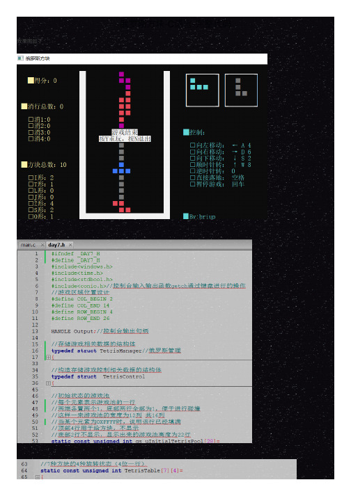
效果图如下
俄罗斯方块-C语言-完整代码
#ifndef _DAY7_H #define _DAY7_H #include<windows.h> #include<time.h> #include<stdbool.h> #include<conio.h>//控制台输入输出函数getch通过键盘进行的操作 //游戏区域位置设计 #define COL_BEGIN 2 #define COL_END 14 #define ROW_BEGIN 4 #define ROW_END 26
纹理物体缺陷的视觉检测算法研究--优秀毕业论文
摘 要
在竞争激烈的工业自动化生产过程中,机器视觉对产品质量的把关起着举足 轻重的作用,机器视觉在缺陷检测技术方面的应用也逐渐普遍起来。与常规的检 测技术相比,自动化的视觉检测系统更加经济、快捷、高效与 安全。纹理物体在 工业生产中广泛存在,像用于半导体装配和封装底板和发光二极管,现代 化电子 系统中的印制电路板,以及纺织行业中的布匹和织物等都可认为是含有纹理特征 的物体。本论文主要致力于纹理物体的缺陷检测技术研究,为纹理物体的自动化 检测提供高效而可靠的检测算法。 纹理是描述图像内容的重要特征,纹理分析也已经被成功的应用与纹理分割 和纹理分类当中。本研究提出了一种基于纹理分析技术和参考比较方式的缺陷检 测算法。这种算法能容忍物体变形引起的图像配准误差,对纹理的影响也具有鲁 棒性。本算法旨在为检测出的缺陷区域提供丰富而重要的物理意义,如缺陷区域 的大小、形状、亮度对比度及空间分布等。同时,在参考图像可行的情况下,本 算法可用于同质纹理物体和非同质纹理物体的检测,对非纹理物体 的检测也可取 得不错的效果。 在整个检测过程中,我们采用了可调控金字塔的纹理分析和重构技术。与传 统的小波纹理分析技术不同,我们在小波域中加入处理物体变形和纹理影响的容 忍度控制算法,来实现容忍物体变形和对纹理影响鲁棒的目的。最后可调控金字 塔的重构保证了缺陷区域物理意义恢复的准确性。实验阶段,我们检测了一系列 具有实际应用价值的图像。实验结果表明 本文提出的纹理物体缺陷检测算法具有 高效性和易于实现性。 关键字: 缺陷检测;纹理;物体变形;可调控金字塔;重构
Keywords: defect detection, texture, object distortion, steerable pyramid, reconstruction
II
Adobe Acrobat SDK 开发者指南说明书

This guide is governed by the Adobe Acrobat SDK License Agreement and may be used or copied only in accordance with the terms of this agreement. Except as permitted by any such agreement, no part of this guide may be reproduced, stored in a retrieval system, or transmitted, in any form or by any means, electronic, mechanical, recording, or otherwise, without the prior written permission of Adobe. Please note that the content in this guide is protected under copyright law.
- 1、下载文档前请自行甄别文档内容的完整性,平台不提供额外的编辑、内容补充、找答案等附加服务。
- 2、"仅部分预览"的文档,不可在线预览部分如存在完整性等问题,可反馈申请退款(可完整预览的文档不适用该条件!)。
- 3、如文档侵犯您的权益,请联系客服反馈,我们会尽快为您处理(人工客服工作时间:9:00-18:30)。
GB Training
□ 各位的期待事项
• 请按TEAM别填写Flip chart. (20分钟) 请按TEAM别填写Flip chart. (20分钟 TEAM别填写 分钟) • Presentation
“ SMD Six Sigma = 成长引擎 “
1.1-9
职 责 (Roles)
GB Training
1. 1. 1. 1. 2. 3. 了解6SIGMA的概念。 了解6SIGMA的概念。 的概念 了解6SIGMA特征。 了解6SIGMA特征。 特征 了解6SIGMA方法论。 了解6SIGMA方法论。 方法论 了解课题的发掘及选定(Selection), 定义(Definition), 登录 定义(Definition), 了解课题的发掘及选定( Chartering)时必要的顺序 时必要的顺序。 (Chartering)时必要的顺序。 你能够对自己的Project作出正确的定义 Definition) 你能够对自己的Project作出正确的定义 (Definition) 。 Project 组成Project team,并明确目标 得到Champion的承认。 并明确目标, Champion的承认 组成Project team,并明确目标,得到Champion的承认。
Step3 PJT 承认 Step2 PJT 定义 Step1 PJT 选定 背景陈述) (背景陈述)
Business 机会分析 Customer 定义 VOC~CTQ 导出 PJT 选定 推进背景 问题及目标陈述 效果计算 PJT 范围 推进日程 TEAM 选定 PJT执行计划书制定 执行计划书登录 执行计划书承认 PJT公式化
GB Training
结果
Define完了的报告书 Define完了的报告书
“ SMD Six Sigma = 成长引擎 “
1.1-4
议 程 (Agenda)
Overview 进行 Step Overview Define Measure Analyze Improve Control
“ SMD Six Sigma = 成长引擎 “
GB Training
Step 2 – PJT定义 定义
设定PJT的目标和范围 的目标和范围. 设定 的目标和范围 选定背景, 选定背景 问题陈述 顾客及 CTQ PJT的 Y 选定 的 现水准及目标陈述 效果计算(预想 效果计算 预想) 预想 战略联系及PJT范围选定 范围选定 战略联系及 组建TEAM及推进日程 及推进日程 组建
GB Training
Control
“ SMD Six Sigma = 成长引擎 “
1.1-6
议 程 (Agenda)
Define 详细执行内容
Step Step 1 PJT选定 背景陈述) 选定(背景陈述 选定 背景陈述
展开到该 Project的过程 的过程 事业环境及机会分析 VOC的导出 的导出 CTQ 优先排序 与战略的关联性评价 PJT选定 选定
GB Training
Six Sigma 概念理解
Sigma的介绍 定义, 特征, 成果因素) Six Sigma的介绍 (定义, 特征, 成果因素) Sigma方法论 Six Sigma方法论 推进战略 Belt的作用及责任 的作用及责任) 推进组织 (Belt的作用及责任)
PJT发掘 PJT发掘/选定 发掘/ 及管理
GB Training
Define Orientation
“ SMD Six Sigma = 成长引擎 “
1.1-1
SPACER
GB Training
Safety (安全 安全) 安全 Purpose (目的 目的) 目的 Agenda (议程 议程) 议程 Code of Conduct (态度 态度) 态度 Expectations (要求事项 要求事项) 要求事项 And Roles (职责 职责) 职责
职责
1. 讲师 :
2. 参与者 – 各位
“ SMD Six Sigma = 成长引擎 “
1.1-10
Charter 检查练习
GB Training
目标:
−
为了PROJECT正确定义, 可以测量, 跟财务目标有关联
方法:
− − − −
分为3-5名组成的小组. 各PROJECT LEADEL应对小组成员说明 Charter接受建设性批判. 必要的话修整 Charter. 在其他小组面前发表 Charter准备.
“ SMD Six Sigma = 成长引擎 “
1.1-8
期待事项 (Expectations)
□ 讲师的期待事项
能够明确定义与战略目标相关的Business改善机会. Business改善机会 1. 能够明确定义与战略目标相关的Business改善机会. 能够明确顾客,并根据VOC导出顾客的Needs VOC导出顾客的Needs. 2. 能够明确顾客,并根据VOC导出顾客的Needs. 能够导出满足Business改善机会和顾客的Needs Business改善机会和顾客的Needs的 3. 能够导出满足Business改善机会和顾客的Needs的CTQ. 能够掌握通过CTQ的详细展开选定PJT的顺序. CTQ的详细展开选定PJT的顺序 4. 能够掌握通过CTQ的详细展开选定PJT的顺序. 能够说明选定的PJT推进背景和问题/目标,并计算出期待效果. PJT推进背景和问题 5. 能够说明选定的PJT推进背景和问题/目标,并计算出期待效果. 能够建立PJT推进组织,并确定推进范围和日程. PJT推进组织 6. 能够建立PJT推进组织,并确定推进范围和日程. 能够将学到的各种技法在各部门有效地使用. 7. 能够将学到的各种技法在各部门有效地使用. 能够将6SIGMA的tool教给GB,并且达到现有BB同等水平的业务水平. 教给GB BB同等水平的业务水平 8. 能够将6SIGMA的tool教给GB,并且达到现有BB同等水平的业务水平. 能够提供发挥能力的机会. 9. 能够提供发挥能力的机会. • 正确的PJT选定及定义 正确的PJT选定及定义 PJT
承认的PJT执行计划书 执行计划书 承认的 已验证的预想财务效果 PJT公式的确定 公式的确定
“ SMD Six Sigma = 成长引擎 “
1.1-7
态 度 (Code of Conduct)
GB Training
1. 要忠实于作为GB 学员的职责,并积极的参与活动。 要忠实于作为GB 学员的职责,并积极的参与活动。 2. 要忠实于作为组员的职责。 要忠实于作为组员的职责。 3. 有疑难问题,可以随时提问。 有疑难问题,可以随时提问。 4. 要认真上课,随时准备接受新的想法 要认真上课, 5. 请遵守时间。 请遵守时间。 6. Please, Turn off the cell phones.
“ SMD Six Sigma = 成长引擎 “
1.1-11
“ SMD Six Sigma = 成长引擎 “
1.1-2
安 全 (Safety)
GB Training
失去了健康, 失去了健康,那么 名誉也就…… 砰 钱、 名誉也就
“ SMD Six Sigma = 成长引擎 “
1.1-3
目 标 (Purpose)
通过具(Tools) 工具
KJ 法, Pareto Chart SPC, Graph CTQ 详细展开 (Flow Down) SWOT分析 KANO分析 分析, 分析 分析 QFD, Brainstorming Benchmarking Customer Research PJT选定背景陈述 选定背景陈述 PJT的 VOC, CTQ 目录 的 事业机会分析表 PJT目录 目录
Stakeholder Analysis SIPOC/COPIS Process Map Graph SPC 工程能力 PJT执行计划书 执行计划书 (Charter 及详细内容 及详细内容)
Sigma Park 登录 FEA 验证基准 Team management
结果 (Deliverables)
顾客 VOC/VOB/CTQ PJT发掘 发掘/ PJT发掘/选定的 Process PJT管理系统 PJT管理系统
Sigma 尺度
平均, 散布) 尺度的理解 (平均, 散布) DPU/DPO/DPMO/RTY Sigma 水准 COPQ
1.1-5
议 程 (Agenda)
Define 进行 Step Define Measure Analyze Improve
Step 3 – PJT承认 承认
登录PJT执行计划并得到承认 执行计划并得到承认. 登录 执行计划并得到承认 关联部门的协调及合议 PJT登录及承认 登录及承认 PJT正式化 正式化
定义(Definition) 陈述选定 陈述选定PJT的过程和必要性 的过程和必要性. 定义 的过程和必要性
活动(Activity) 活动