Buried Charge Enginering Model - Verification and Validation
保时捷车型维修指南说明书
Vehicle Ident. No. _______________________Working instruction for order no.! Maintenanceat 60,000, 120,000, 180,000, 240,000 km etc./36,000, 72,000, 108,000, 144,000 miles etc.(Labour operation 03 16 00 ..)For a description of the various models, see Technical Manual Mix fuel in fuel tank with additive (Keropur from Porsche; Part No. 000 043 206 89)The term 'checking' includes all necessary subsequent work, such as adjusting, readjusting, correcting and topping up, but does not include repairing, replacing and reconditioning parts or assemblies.Change engine oil and oil filter (please observe oil change service plan for the 911 Carrera, Boxster and Cayman)"Note: If the mileage for a regular service is not reached, maintenance must be carried out after 4, 8, 12...... years.911 Carrera (997), 911 Carrera S (997)Boxster (987), Boxster S (987)as of 2009 modelDiagnostic system: read out fault memory; reset maintenance intervalVehicle underbody and engine compartment:visual inspection for leaks (oils and fluids)and chafing damage (lines and hoses)Continued overleaf Copyright byElectrical equipment, warning and indicator lights: check operationVehicle lighting: check operationAll headlights: check adjustmentHorn: check operationHandbrake: check free play of handbrake leverExhaust system: visual inspection for leaks and damage, check engine mountBrake hoses and lines: visual inspection for leaks, damage, routing and corrosionSteering gear: visual inspection of the bellows for damageTie rod joints: check the play and dust bootsSeat belts: check operation and conditionAir cleaner: replace filter elementFuel system: visual inspection for damage, routing and secure fit of line connectionsParticle filter: replace filter elementDrive shafts: visual inspection of the boots for leaks and damageBrake system: visual inspection of the brake pads and brake discs for wearTyres: check condition and tyre pressureCheck the door locks, lid locks and safety hooks of the front lid to ensure that they are secure and functioning properly Axle joints: check the play and visually inspect the dust boots for damageVehicle underbody and engine compartment: visual inspection for leaks (oils and fluids) and chafing damage (lines and hoses)Underbody panels: visual inspection for completeness, secure installation and damageCoolant hoses: check conditionRadiators and air inlets: visual inspection for external contamination and blockageCoolant: check level and antifreezeWindscreen wiper/washer system, headlight cleaning system: check fluid level and nozzle settings,check antifreeze in winter months; check wiper bladesReplace spark plugs: see Additional maintenanceBattery: check functional state and fluid levelpy g y Dr. Ing. h. c. F. Porsche AGAfter Sales EngineeringPrinted in Germany - 11/08Vehicle Ident. No. _______________________Working instruction for order no.! Additional maintenance for spark plugs(Labour operation 03 81 00 ..)"! Additional maintenance for drive belt (Labour operation 03 60 00 ..)! Additional maintenance for convertible top(Labour operation 03 70 00 ..)! Additional maintenance every 90,000 km/54,000 miles or every 6 years (Labour operation 03 83 00 ..)as of 2009 modelService and maintain convertible top (911 Carrera only)every 30,000 km/18,000 miles or every 2 years Replace spark plugs every 30,000 km/18,000 miles or every 4 years Check drive belt every 60,000 km/36,000 miles or every 4 years every 150,000 km/90,000 miles or every 10 years Check drive beltCheck drive belt every 240,000 km/144,000 miles or every 16 years Boxster (987), Boxster S (987)R l d i b lt911 Carrera (997), 911 Carrera S (997)Controlled all-wheel (only Carrera 4) : change oil! Additional maintenance every 180,000 km/108,000 miles or every 12 years(Labour operation 03 88 00 ..)! Every 2 yearsFile condition report for long-life guarantee! Every 4 years! After 4 years, then every 2 years! After 4, 8, 10 years, then every 2 yearsSignature (mechanic): _______________________________Test drive:Oils, fluids: visual inspection for leaksSignature (final check): _________________________Remote control, front seats, footbrake and handbrake (also actuation travel), engine, clutch, steering, transmission, ParkAssist, cruise control, PSM switch, PASM switch, Sport switch, heating, air conditioning and instruments: check operation Manual transmission: change oilAncillary unit mounts and suspension: visual inspection of all rubber mountings and boots for damageChange brake fluidReplace tyre sealantCheck tyre pressure monitoring system batteryPDK transmission: change clutch fluidReplace drive belt PDK transmission: change transmission oilAll-wheel final drive: change oil (911 Carrera only)Copyright byDr. Ing. h. c. F. Porsche AGAfter Sales EngineeringPrinted in Germany - 11/08Porsche Centre。
2.1 Emerge

mm/0.046’’ 3.2F/1.09 mm/0.043” 3.2F/1.09 mm/0.043” 3.4F/1.16 (所有尺寸) 0.014”/0.36 mm 0.014”/0.36 mm 0.014”/0.36 mm
IC-74203-AB 2012年9月
波士顿科学公司 Confidential. For Internal Use Only. Do Not Copy, Display or Distribute Externally. IC-70608-AA March 2012
• 激光焊接技术 • 核心钢丝技术 • 尖端成型工艺 • 新型球囊材料 • 特殊涂层技术
Apex
• 双节段内轴杆 • 新型聚酯袖套 • Slope外轴杆技术 • 改良的球囊材料 • 技术先进的头端设 计 • 更薄更短的标记带
Quantum Maverick
• Maverick输送平台 • 特殊球囊材质
减少的轴剖面 与Maverick相似的轴性能
规格 Emerge™ 导管 2个铂金标记带 (2.0-4.0 mm) 标记带 1个居中铂金标记带 (1.2 -1.5 mm) 0.017”/0.43 mm 8-20 mm长度: 2.3F(1.2-2.0 mm) 2.4F(2.25-3.25 mm) 2.7F(3.5-4.0 mm) Apex™ 导管 Maverick™ 导管 2个金(2.0 mm和更大 直径) 1个居中金(1.5 mm)
Flextome切割 球囊
• 改良的输送平台 • 改良的刀片设计 • 非顺应性球囊材质
PTCA 扩张导管
红色头端 降低轴杆外径,便于球囊 对吻 0.017”/0.43 mm 头端剖面
新型ZGlide™ 亲水涂层
双节段内轴杆
某PHEV_燃油箱加油反喷问题研究及对策
2023年第6期某PHEV燃油箱加油反喷问题研究及对策刘学敏,邓湘,卜江华,金永镇,郭亚威(岚图汽车科技有限公司,武汉 430056)摘 要:针对某插电式混合动力汽车燃油箱加满油的瞬间燃油反喷的故障,结合插电式混合动力燃油系统的工作原理及故障处理经验,分析故障产生的根本原因,提出相应的改进措施,同时优化了技术设计标准,补充完善了试验规范中加油枪的型号要求,对之后的燃油箱设计和加油性能验证方面有一定的指导作用。
推荐的加油反喷改善措施,具有技术可行、实施周期短、成本低廉、效果良好的优点,可供借鉴。
关键词:插电式混合动力;燃油箱;反喷中图分类号:U473 文献标志码:A 文章编号:1005-2550(2023)06-0011-05Research and Countermeasures of Refueling Spit back in a PHEVFuel TankLIU Xue-min, DENG Xiang, BU Jiang-hua, JIN Yong-zhen, GUO Ya-wei( Lantu Automobile T echnology Co., Ltd., Wuhan 430056, China)Abstract: In view of the fault of fuel spit back when the fuel tank of a plug-in hybrid vehicle is filled with fuel, combined with the working principle and fault handling experienceof the plug-in hybrid fuel system, this paper analyzes the root causes of the fault and putsforward corresponding improvement measures. At the same time, it optimizes the technicaldesign standard and supplements and perfects the model requirements of the fuel gun inthe test specification, It provides important experience feedback and design guidance forsubsequent projects in the development and approval of fuel tank.Key Words: Plug-In Hybrid; Fuel T ank; Spit Backdoi:10.3969/j.issn.1005-2550.2023.06.003 收稿日期:2023-08-24刘学敏毕业于武汉理工大学大学,学士学位。
基于EDEM_的单侧犁式卸料器弧形挡料板仿真研究

[9] Ding J,Zheng C Z,Song C C,et al.Experimental Study on the Improvement of Yaw Stability by Coordination Control between the Caudal Fin and Anal Fin[J].Journal of Bionic Engineering,2022:1-11.[10] Omari M,Ghommem M,Romdhane L,et al.Performance analysis of bio-inspired transformable robotic fish tail[J]. Ocean Engineering,2022,244:110 406.[11] 成玉强,帅长庚.单关节尾鳍驱动式机器鱼的运动分析 与仿真[J].海洋技术学报,2018,37(6):7-14.[12] Lighthill M J.Large-amplitude elongated-body theory of fish locomotion[J].Proceedings of the Royal Society of London,Series B:Biological Sciences,1971,179: 125-138.[13] Vignesh D,Krishnankutty P.Numerical Study on Biomimetic Flapping Foil Propulsion System in Open Water Condition[C].OCEANS 2022-Chennai.IEEE,2022:1-5.[14] 李林.鲹科鱼类游动力学特性的理论与仿真研究[D].哈尔滨:哈尔滨工业大学,2008.作 者:高鑫驰电子邮箱:****************收稿日期:2022-12-04基于EDEM的单侧犁式卸料器弧形挡料板仿真研究*姚艳萍 古向宇 郭振海 陈 壮太原科技大学机械工程学院 太原 030024摘 要:犁式卸料器是带式输送机的关键装置,针对挡料板的磨损问题,文中分析了磨损机理并制作了仿真模型,通过EDEM进行仿真试验,重点研究了在相同工况下不同曲率的挡料板对卸料速度、挡料板的磨损,通过改变挡料板曲率半径的大小分析了冲击磨损和平均速度之间的关系。
TH8062中文资料
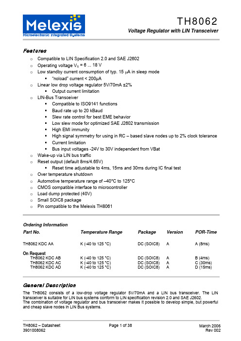
Featureso Compatible to LIN Specification 2.0 and SAE J2602o Operating voltage V S = 6 ... 18 Vo Low standby current consumption of typ. 15 μA in sleep mode“noload” current < 200µAo Linear low drop voltage regulator 5V/70mA ±2%Output current limitationo LIN-Bus TransceiverCompatible to ISO9141 functionsBaud rate up to 20 kBaudSlew rate control for best EME behaviorLow slew mode for optimized SAE J2602 transmissionHigh EMI immunityHigh signal symmetry for using in RC – based slave nodes up to 2% clock toleranceCurrent limitationBus input voltages -24V to 30V independent from VBato Wake-up via LIN bus traffico Reset output (default 8ms/4.65V)Reset time adjustable to 4ms, 15ms and 30ms during IC final test o Over temperature shutdowno Automotive temperature range of –40°C to 125°Co CMOS compatible interface to microcontrollero Load dump protected (40V)o Small SOIC8 packageo Pin compatible to the Melexis TH8061Ordering InformationPart No. Temperature Range Package Version POR-Time TH8062 KDC AA K (-40 to 125 °C) DC (SOIC8) A A (8ms)On RequestTH8062 KDC AB K (-40 to 125 °C) DC (SOIC8) A B (4ms) TH8062 KDC AC K (-40 to 125 °C) DC (SOIC8) A C (30ms) TH8062 KDC AD K (-40 to 125 °C) DC (SOIC8) A D (15ms) General DescriptionThe TH8062 consists of a low-drop voltage regulator 5V/70mA and a LIN bus transceiver. The LIN transceiver is suitable for LIN bus systems conform to LIN specification revision 2.0 and SAE J2602.The combination of voltage regulator and bus transceiver makes it possible to develop simple, but powerful and cheap slave nodes in LIN Bus systems.Contents1.Functional Diagram (4)2.Electrical Specification (5)2.1Operating Conditions (5)2.2Absolute Maximum Ratings (5)2.3Static Characteristics (6)2.3.1.Voltage Regulator and Reset Unit (6)2.3.2.LIN Bus Interface (8)2.4Dynamic Characteristics (9)2.5Timing Diagrams (11)3.Functional Description (13)3.1Operating Modes (13)3.2Initialization (15)3.3Wake-Up (15)3.4VSUP under voltage reset (16)3.5Overtemperature Shutdown (16)3.6LIN BUS Transceiver (17)3.7Linear Regulator (20)3.8RESET (21)3.8.1.Programmability of Power-ON-Reset Delay (21)3.9Mode Input EN (22)4.Application Hints (24)4.1Safe Operating Area (24)4.2Low Dropout Regulator (25)4.3Application Circuitry (27)4.4EMI Supressing (27)4.5Connection to Flash-MCU (28)5.Operating during Disturbance (29)5.1Operating without VSUP or GND (29)5.2Short Circuit BUS against VBAT (29)5.3Short Circuit BUS against GND (29)5.4Short Circuit TxD against GND (29)5.5TxD open (29)5.6Short Circuit VCC against GND (29)5.7Overload of VCC (29)5.8Undervoltage VCC (29)5.9Undervoltage VSUP (30)5.10Short circuit RxD, RESET against GND or VCC (30)6.PIN Description (31)7.Mechanical Specification (32)8.Tape and Reel Specification (33)8.1Tape Specification (33)8.2Reel Specification (34)9.ESD/EMC Remarks (35)9.1General Remarks (35)9.2ESD-Test (35)9.3EMC (35)10.Revision History (36)11.Assembly Information (37)12.Disclaimer (38)List of FiguresFigure 1 - Block diagram (4)Figure 2 - Timing diagram for propagation delays (11)Figure 3 - Timing diagram for duty cycle acc. to LIN 2.0 and J2602 (11)Figure 4 - Timing Diagram for EN mode selection (12)Figure 5 - State diagram of operating modes (13)Figure 6 - Operating of power-on and under-voltage reset (15)Figure 7 - Receive mode impulse diagram (17)Figure 8 - TxD input circuitry (18)Figure 9 - RxD output circuitry (19)Figure 10 - Characteristic of current limitation VCC = f (I VCC) (20)Figure 11 - Reset behaviour (21)Figure 12 - Output current of reset output vs. VCC voltage (21)Figure 13 - EN input circuitry (22)Figure 14 - EN controlled via MCU (22)Figure 15 - Permanent normal mode (23)Figure 16 - Power dissipation LIN transceiver @ 20kbit (24)Figure 17 - Save operating area (25)Figure 18 - ESR Curves for 6.8μF ≤ C L≤ 100μF and Frequency of 100 kHz (26)Figure 19 - Application circuit (slave node) (27)Figure 20 – Example circuitry for connection of RxD to MCU for flash programming (28)Normal ModeThis mode is the base mode. The bus transceiver is able to send with a max baud rate of 20kbit/s.The whole TH8062 is active. Switching to normal mode can be done via the following actions: - Start of V SUP or after under voltage reset- Rising edge at EN (EN=high) and TxD=high (local wake-up)- Activity on the LIN bus (remote wake-up)Sleep ModeSleep mode is most current saving. With a falling edge on EN (EN=low) the TH8062 is switched from normal mode into sleep mode. The voltage regulator and the reset unit will be switched off and the LIN transceiver is in recessive state.Switching into sleep mode can be done independently from the current transceiver state. That means if the transmitter is in dominant state this state will be cancelled and it will be switched to recessive state.Low Slew ModeIn this mode the slew rate is switched from the normal value of typ. 1.6V/µs to a low value of typ. 0.8V/µs. This mode is optimized to send with a maximum baud rate of 10.4kbit/s (SAE J2602). Because of this reduction of the slew rate the EME behaviour is improved especially in the frequency range of 100 kHz to 10MHz.Switching to this mode is possible with a combination of rising edge on EN together with a low level on TxD. The IC operates in this mode until the next under voltage reset occurs.POR-stateThis is the power-on-reset state of the TH8062, while Vsup < V SUVR_OFF. If the prior state was sleep mode, the TH8062 switches via the ini-state to normal mode.Ini-stateThis is an intermediate state, which will pass through after switch on of VSUP or VCC. The TH8062 remains in this state if V CC is below V RES (Reset output = L) and Vsup > V SUVR_ON.Thermal ShutdownIf the junction temperature T J is higher than T JSHD (>155°C), the TH8062 will be switched into the thermal shutdown mode. The behaviour within this mode is comparable with the sleep mode except for LIN transceiver operating. The transceiver is completely disabled; no wake-up functionality is available.If T J falls below the thermal recovery temperature T JREC (typ. 140°C) the TH8062 will be recover to the previous state (normal, sleep or low slew).3.4 VSUP under voltage resetThe under voltage detection unit inhibits an undefined behaviour of the TH8062 under low voltage condition (VSUP < 4V). If VSUP drops below V SUVR_ON (typ. 3.1V) the under voltage detection becomes active and the IC will be switched to POR state. The following increasing of VSUP above V SUVR_OFF (typ. 3.7V) cancels this POR state and the voltage regulator starts with the initialization sequence.VSUP under voltage in Normal ModeSupply Voltages below V SUVR_OFF do not influence the voltage regulator. The output voltage Vcc follows VSUP.VSUP under voltage in Sleep ModeNo exit from the sleep mode will take place if the VSUP voltage drops down to V SUVR_ON (typ. 3.5V). The under voltage reset becomes active (POR-state) if the voltage drops below 2.7V. As a result of this functioning, the sleep mode is left to the normal mode. If VSUP rises again above V SUVR_OFF (typ. 4.2V) the IC initializes the voltage regulator and continues to work with the normal mode.The under voltage reset unit secures stable functioning in the under voltage range of VSUP down to GND level. The dynamic Power-On-Reset secures a defined internal state independent from the duration of the VSUP drop, which guarantees a stable restart.VSUP under voltage in Low Slew ModeThe behaviour of TH8062 at low VSUP voltages is equal to the sleep mode. The low slew mode will be cancelled, if VSUP drops below V SUVR_ON in this mode. The TH8062 enters the normal mode, if VSUP rises again above V SUVR_OFF.3.5 Overtemperature ShutdownIf the junction temperature is 155°C < T J < 175°C the over-temperature recognition will be activated and the regulator voltage will be switched off. The V CC voltage drops down, the reset state is entered and the bus-transceiver is switched off (recessive state).After T J falls below 140°C the TH8062 will be initialized again (see Figure 11). This initialisation starts independently from the voltage levels on EN and BUS. Within the thermal shutdown mode the transceiver can not switch to the normal mode neither with local nor with remote wake-up.The operation of the TH8062 is possible between T Amax (125°C) and the switch off temperature, but small parameter differences can appear.After over-temperature switch-off the IC behaves as described in chapter 3.8 RESET.Figure 12 - Output current of reset output vs. VCC voltage Programmability of Power-ON-Reset Delay4. Application Hints4.1 Safe Operating AreaThe maximum power dissipation depends on the thermal resistance of the package and the PCB, the temperature difference between Junction and Ambient as well as the airflow. The power dissipation can be calculated with: P D = (V SUP – V CC ) * I VCC + P D_TXThe power dissipation of the transmitter P D_TX depends on the transceiver configuration and its parameters as well as on the bus voltage V BUS =V BAT -V D , the resulting termination resistance R L , the capacitive bus load C L and the bit rate. Figure 16 shows the dependence of power dissipation of the transmitter as function of V SUP . The conditions for calculation of the power dissipation is R L =500Ω, C L =10nF, bit rate=20kbit and duty cycle on TxD of 50%055045403530252015105191817161514131211109876P D [m W ]V SUP [V]Figure 16 - Power dissipation LIN transceiver @ 20kbitThe permitted package power dissipation can be calculated:ATHJ j D R T −−=Amax T PIf we consider that P D_TX_max = f (V SUP ) the max output current I VCC on V CC can be calculated:VCCVSUP P R T VSUPTX D ATHJ j V −−−=−@max __ACCmax T IT J -T A is the temperature difference between junction and ambient and R th is the thermal resistance of the package. The thermal energy is transferred via the package and the pins to the ambient. This transfer can be improved with additional ground areas on the PCB as well as ground areas under the IC.5.Operating during Disturbance5.1 Operating without VSUP or GNDThe absence of V SUP or GND connection will not influence or disturb the communication between other bus nodes. No reverse supply of the IC can appear if without GND or VSUP connection the BUS pin is on VBAT level.5.2 Short Circuit BUS against VBATThe reaction of the IC depends on the send state of the transceiver:- Recessive LIN bus is blocked, no influence to the TH8062- Dominant Current limitation, thermal shut down of TH8062 if power dissipation will make an overrun of T J5.3 Short Circuit BUS against GNDLIN bus is blocked. No influence on the TH8062.5.4 Short Circuit TxD against GNDThe LIN transceiver is permanently in the dominant state, which means the whole LIN bus. This state can only be detected from the LIN controller. In this case the controller must switch off the LIN node via the EN input of the TH8062. A thermal shut down of TH8062 will appear if the power dissipation will make an overrun of T J.5.5 TxD openThe internal pull-up resistor forces the LIN node to the recessive state. The communication between the other bus-nodes will not be disturbed.5.6 Short Circuit VCC against GNDThe VCC pin is protected via a current limitation. This state is comparable with the behaviour in the sleep mode.5.7 Overload of VCCThermal switch offThe power dissipation is increasing if the load current is between I VCC_max and I LVCC. If the max junction temperature of >155°C is reached, the IC will be switched off. The voltage regulator will also be switched off and a reset signal is forced.Over currentIf the current limitation is active the voltage on VCC drops down. If this voltage under-runs the threshold V RES, a reset will be forced.5.8 Undervoltage VCCThe reset unit ensures the correct behaviour of the driver during under-voltage. The BUS pin generates the recessive state if V CC < V MRes (3.15V). The inputs EN and TxD have pull-up or pull-down characteristics.If V CC≥ V MRes the TxD signal is transmitted to the bus. The receive mode is also active.5.9 Undervoltage VSUPThe combination of dynamic power on reset and low voltage reset guarantees a defined start up behaviour. If the supply voltage VSUP drops below 3V the low voltage detection becomes active. If the VSUP voltage rises again above 3.5V the low voltage reset will be terminated and the 5V voltage regulator will be started. 5.10 Short circuit RxD, RESET against GND or VCCBoth outputs are short circuit proof to VCC and ground.9.ESD/EMC Remarks9.1 General RemarksElectronic semiconductor products are sensitive to Electro Static Discharge (ESD).Always observe Electro Static Discharge control procedures whenever handling semiconductor products. 9.2 ESD-TestThe TH8062 is tested according CDF-AEC-Q100-002 / MIL883-3015.7 (human body model).9.3 EMCThe test on EMC impacts is done according to ISO 7637-1 for power supply pins and ISO 7637-3 for data-and signal pins.12.DisclaimerDevices sold by Melexis are covered by the warranty and patent indemnification provisions appearing in its Term of Sale. Melexis makes no warranty, express, statutory, implied, or by description regarding the information set forth herein or regarding the freedom of the described devices from patent infringement. Melexis reserves the right to change specifications and prices at any time and without notice. Therefore, prior to designing this product into a system, it is necessary to check with Melexis for current information. This product is intended for use in normal commercial applications. Applications requiring extended temperature range, unusual environmental requirements, or high reliability applications, such as military, medical life-support or life-sustaining equipment are specifically not recommended without additional processing by Melexis for each application.The information furnished by Melexis is believed to be correct and accurate. However, Melexis shall not be liable to recipient or any third party for any damages, including but not limited to personal injury, property damage, loss of profits, loss of use, interrupt of business or indirect, special incidental or consequential damages, of any kind, in connection with or arising out of the furnishing, performance or use of the technical data herein. No obligation or liability to recipient or any third party shall arise or flow out of Melexis’ rendering of technical or other services.© 2002 Melexis NV. All rights reserved.For the latest version of this document. Go to our website atOr for additional information contact Melexis Direct:Europe and Japan: All other locations:Phone: +32 1367 0495 Phone: +1 603 223 2362E-mail: sales_europe@ E-mail: sales_usa@ISO/TS16949 and ISO14001 Certified。
威猛巴顿菲尔
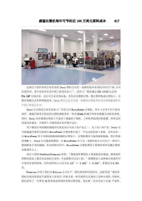
威猛注塑机每年可节约近100万美元原料成本 617总部位于纽约州埃尔布里奇的Tessy塑料公司是一家拥有海外业务的合约生产商,公司在纽约州、弗吉尼亚州以及中国上海设有加工厂,这些工厂都是通过ISO 13485认证的FDA/GMP合规企业。
该公司专业从事高速、多色以及薄壁注塑、微注塑和集成注塑加工,并拥有装配以及多种增值技术。
Tessy将自己定义为是一家拥有注塑技术以及从事装配部件生产的工程设计公司。
Tessy公司的埃尔布里奇加工厂共有五台MicroPower注塑机,其中4台用于生产医用部件。
威猛巴顿菲尔的这些注塑机都配备有一体式SCARA机械手和带有摄像头的检查系统。
同时,Tessy还在微观注塑加工中选用了威猛的干燥机、上料机和温度控制装置。
所有这些设备均在满足一万级和十万级的清洁室环境中运行。
用于微创手术的腹腔镜缝合钉就是该公司加工的产品之一。
为了加工该产品,Tessy公司将威猛巴顿菲尔的两台MicroPower注塑机整合成了一个自动化的加工系统。
另外还有一台MicroPower用于印刷电路板隔离器的注塑加工。
注塑机模具与隔离器相接触,然后焊接到PCB上。
Tessy公司最新购置的一台MicroPower专门为一家眼科医疗公司生产一种用于微观眼部手术的器械。
在这两种应用中,MicroPower注塑机都用于将塑料部件包覆注塑到金属部件之上。
项目工程师Stafford Frearson讲到,“微观部件模塑加工要面临很多挑战。
微观部件和模具的加工都具有高度的专业性,不是谁都可以加工的。
”要模塑加工这种细小的部件可不是件容易的事情,有些部件的大小仅为0.120" × 0.063" × 0.038",重量仅为0.004克。
Frearson介绍了他们为Ethicon公司生产一款钉匣部件时的经历,这样讲道“我们在投标并成功拿到这个滤筒加工业务后,开始寻求一种全新的方式来加工这种小部件。
W+B-中国代表处

传承瑞士的精准风格
地处瑞-德边界,融合瑞士的精准和德国的严谨 体现最高欧洲工业制造水准
从标准产品到客户定制
从静态到动态
从 桌 面 到 大 型
从整机到附件
为全球知名试验机公司产品改造
多功能疲劳试验机
W+B公司为全球生产顶 级疲劳试验机。 产品从桌面电子式到大 型液压伺服。 吨位从0.1吨到3000吨。 配备各种夹具、高低温 箱、激光引伸计、视频 引伸计,完成各类试验。
各类疲劳试验机
应用于多种试验
最先进的控制器
超强的扩展 功能
W+B公司旗下近三十年历史的专业软件公司 提供各类成熟可靠的软件
各类动静态自由编程
软件包
液压油源大 型 泵 站 Nhomakorabea大型电液伺服作动器是W+B的骄傲
为客户定制
感谢您的关注!
• W+B中国代表处 • 中国南京中山南路369号 • 电话:86 25 8449 2327
基于BP神经网络的非致命武器研发费用预测
S) 也 简称 为神 经网络 ( N ,是模拟生物神经网络 , N s)
进行信息处理的一种数学模型。它 以对大脑 的生理研究成 果为基础 ,其 目的在于模拟大脑 的某些机理与机制 ,实现
一
些特定 的功能。 目前 ,神经网络按网络结构和学习算法
可分 为很多种 ,P B 网络 是 目前运 用最 为广泛 的神经 网络模
∑ ∑ Y 】 = ∑ {- l
K K J \ /
式 中K 为输入输 出模式对序列 ;
ቤተ መጻሕፍቲ ባይዱ( 修正权值 5)
图 1 P 经 网 络 模 型 B 神
( 1 I , △( (式 中 为 练次数 , 为 t ) ( ) ) ) =( ( of )
学习率, ( = , △ ∑6 , ) Y
B P算法的学习过程是由正 向传播和反 向传播两个过
测 需考虑到武器 系统研发 费用的非线性 特点和非致命武
器装备 自身的特点 , 本文采 用人 工神 经网络预测法对非致
命武器的研发费用进行预测 。
程组成的 , 在正 向传播过程中 , 输入信息从输入层经隐含
层逐层处理 ,并传向输 出层 ,每一层神经元的状态只影 响 下一层神经元 的状态。如果在输 出层不能得到期望输出 , 则转入反向传播将误差信号沿原来 的连接通路返回 ,把网 络学 习时输 出层 出现的与 “ 事实”不符的误差 ,归结为连 接层 中各节点 间连 接权及 阈值 ( 有时将阈值作为特殊的连 接权并入连接权) “ 的 过错 ”,通过把输出层 节点 的误差 逐层向输入层逆向传播 以 “ 分摊 ”给各连接节点 ,从而可 算 出各连接节点的参考误 差, 并据此对各 连接权进行相应 的调 整 ,使 网络适应要求的映射 。B 网络的学 习过程可 P 归纳 为 “ 模式顺传 播一误差逆传 播一记忆训 练一 学 习收 敛 ”4 " 4 过程 。B 网络算法的基本步骤如下 : P ( 一 ,+ ] 1) 1 1之间的随机数初始化各层节点间的 连接权和节点阈值 ; ( 给定输入 2) 和期望输 出j; = , ( 3)计算各层节点的输入n t= e 0和输 出 ,
- 1、下载文档前请自行甄别文档内容的完整性,平台不提供额外的编辑、内容补充、找答案等附加服务。
- 2、"仅部分预览"的文档,不可在线预览部分如存在完整性等问题,可反馈申请退款(可完整预览的文档不适用该条件!)。
- 3、如文档侵犯您的权益,请联系客服反馈,我们会尽快为您处理(人工客服工作时间:9:00-18:30)。
“This value of 66% is significant because it is precisely the same value that has been found on two separate occasions with two different target geometries and target materials tested at DRDC Valcartier test range [2,3].”
presented, and extended, by Tremblay (1998). The implementation is applicable to flat (horizontal) and oblique (angled) target plates consisting of either shell or solid elements. Westine, et al. (1985) performed a series of buried charge experiments using thick (non-deforming) target plates with a set of impulse plugs inserted into holes drilled in the plate. The impulse plugs were spaced at 10 different ranges from the plate center, and hence angles from the center of the buried charge. Detonation of the buried charge forces the impulse plugs vertically out of the plate and measurement of their speed provides an estimate of the momentum (impulse) provided by the buried charge. Using groupings of appropriate non-dimensional parameters, Westine, et al. (1985) construct a plot of all their impulse plug data, and some similar data from the literature (Wenzel, 1972), in the form of scaled specific impulse versus scaled distance. This data is then fit to an analytical function. The result is for a given:
(2)
0.154 A 4.48 z
0
d z
19.3
The parameter c in the second inequality is the seismic P-wave speed in the soil expressed in units of
L T
e.g.
m/s.
buried mine blast loading via the keyword *INITIAL_IMPULSE_MINE. This is an engineering model based upon experimental results, much like the air blast engineering model provided by *LOAD_BLAST_ENHNACED. The model is based on the work of Westine, et al. (1985) as
Tremblay also repeats the Westine, et al. limitations on the nondimensional groupings with respect to the range of the applicable data:
© 2013 Copyright by Arup
9th European LS-DYNA Conference 2013 _________________________________________________________________________________
BURIED CHARGE ENGINEERING MODEL: VERIFICATION AND VALIDATION
Another
limitation
on
Equation
(1),
omitted
by
Tremblay,
is
a
factor
of
1.8
on
the
empirical specific impulse that provides users with an assessment of the equation’s accuracy, viz.
© 2013 Copyright by Arup
9th European LS-DYNA Conference 2013 _________________________________________________________________________________
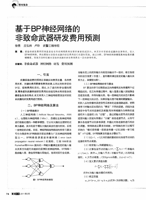
Figure 1 Schematic of the buried mine parameters.
Among the items not considered by Westine, et al., and contributing to the above accuracy estimate are the size of the target plate with respect to the points of interest, i.e. clearing effects for small targets or the lack of clearing for tracked or wheeled vehicles where the blast is further confined.
Len Schwer and Todd Slavik Schwer Engineering & Consulting Services and Livermore Software Technology Corporation
1 Introduction
Livermore Software Technology Corporation (LSTC) recently added an empirically-based model for
9th European LS-DYNA Conference 2013 _________________________________________________________________________________
0.106 1.0 z6.35E/A c2z
150
Williams and McClennan (2002) determined that a 66% reduction in the Westine et al. impulse produced good correlation with their experimental observations for a 6kg charge of C-4 buried 50mm below the surface with a horizontal target plate at a standoff distance of 406.4mm. They also cite two other examples where the 66% reduction was used to improve the correlation with observations:
iv /1.8 expected impulse 1.8iv
(3)
i.e. the specific impulse for a given buried charge scenario is bounded below by dividing the predicted specific impulse from Equation (1) by 1.8 and bounded above by the 1.8 times the predicted specific impulse.
2.1 Horizontal Target Plates
Tremblay begins by reintroducing the Westine, et al. impulse data equation with modifications to the nomenclature to suit his subsequent analytical extensions:
schematic of the buried mine and nomenclature.
2 Analytical Extension
Tremblay (1998) provides an analytical extension to oblique plates, the more common configuration for vehicles subjected to mine blast, based on Westine, et al. (1985) horizontal plate results.
Explosive energy release, E [J] Cross sectional area of the charge, A [m2 ] Soil density, [ kg/m3 ] Standoff distance of the target from the center of the charge, z [m] Depth of burial from the soil surface to the center of the charge, [m] Lateral distance to the point of interest, d [m] The scaled specific vertical impulse, iv is provided at the point of interest, P . Figure 1 provides a