DMP2000扭矩扳子检定仪软件说明书
2000标准负荷测量仪仪表说明书

本手册主要介绍2000标准负荷(扭矩)测量仪的连线、校准、设置和使用方法,请用户在使用前仔细阅读。
一、2000标准负荷测量仪简介2000标准负荷(扭矩)系列测量仪是一款经过10年大量实践检验被最广泛认知的基础力学测量仪器,10年来先进的测量器具在基础力学测量领域中的推广应用和称重传感器在性能、质量、产能以及在世界市场上份额的增加,该系列仪器有着不可磨灭的贡献,应用领域包括:精密力值测量;扭矩测量、材料性能测试、应力应变测量、峰值测量以及基于应变原理传感器的生产检测领域。
相关的产品更新信息请参阅第3页。
2000A型仪表为最常用的测力计配套仪表,具有很高的可靠性和性能价格比,6或40个数据通道,额定显示分度5万,重复性、线性<0.01%FS, AD转换速率50~500次/秒,mV/V量值准确度:0.030%+0.020%(准确度采用相对于读数+相对于量程的不确定度描述方法,以下同),温度系数:<20ppm+10ppm,该款仪表主要应用于当量准确度为0.3%的标准测力计和常规力值测量。
2000B型仪表提供更高的准确度和测量效率,适用于当量准确度为0.1%的标准测力计、标准叠加式测力机和高要求测量需求,6或40个数据通道,显示分度20万,重复性、线性<0.005%FS,mV/V量值准确度:0.015%+0.010%,温度系数:<10ppm+5ppm。
2000D型仪表为扭矩测量仪表,6或40个数据通道,额定显示分度5万,重复性、线性<0.01%FS,AD转换速率50次/秒~500次/秒,mV/V量值准确度:0.030%+0.020%,温度系数:<20ppm+10ppm。
2000E型仪表为应变式传感器检测、补偿和调整的专用仪表,可直接显示传感器输出信号mV/V 的测量值,信号输入范围:-12mV/V~+12mV/V,最小分辨率:0.01 V/V(等效于6.5位数字电压表),重复性、线性<0.005%FS,mV/V量值准确度:0.015%+0.010%,温度系数:10ppm+5ppm,内置传感器供桥电源,可替代“稳压电源+数字万用表”的传感器检测、补偿和调整方法。
数字扭矩仪使用说明书

数字扭矩仪使用说明书Ver 0.01SHIMPO1.本产品的特点z可以测得开栓方向或闭栓方向的扭距z可以用USB向电脑传输数据z可以测得峰值(峰值保持)z存储功能可以最多存储1000个计测时的峰值。
z比对功能可以判断产品的合格与否(判定结果通过LED显示)z由于采用了镍氢电池,没有AC适配器也可以方便地使用。
z额定扭距为2N、5N、10N的机种。
z可以切换为各种单位(国内只可以转换)z计测周期(显示周期)最大可从8次/秒中选择。
2.各部分名称及工作2.1主机部分■ (前面)①Power键键键键键⑥液晶显示部分①Power キー用于电源的开/关②Recall キー开栓计测或闭栓计测模式时读取已存储的数据※平均计测模式时不能读取存储数据。
用于功能模式时③Mem キー在开栓计测或闭栓计测模式下将保持峰值输入、存储。
※平均计测模式下不能存储输入。
用于存储数据完全清除时用于功能模式时。
④Mode キー切换计测模式。
读取存储数据时按本按钮会返回计测模式。
在功能模式时使用。
⑤Zero/RST キー平均计测模式时:进行归零开栓、闭栓计测模式时:进行峰值归位用于功能模式启动时用于功能模式时⑥液晶显示部分显示计测数据、计测单位⑦计测模式显示灯中有一个灯亮,表示计测模式。
⑧对比判定显示灯对比判定有效的情况下,中一个灯亮,表示对比判定结果。
平均模式:对计测数据进行比较、判断后显示其结果。
开栓计测、闭栓计测模式:用比对器对保持了的峰值进行判定,显示结果。
用比对器进行判定无效时,灯不亮。
4/153. 显示部分3.1 各部分名称3.2 数值显示部分用符号和4位数值显示测定值。
开栓方向扭距用正数、闭栓方向的扭距用负数来显示。
3.3 单位显示部分显示单位。
过载的时候显示“OVR ”。
在自动关机前1分钟内显示“PWR ”。
5/15充电显示部分 单位显示部分数值显示部分(测量值显示)自动关机前1分钟内 过载3.4充电显示部分根据充电状态会显示如下数据:内置镍氢电池的电压降低时“LO BAT”闪烁。
扭矩扳手检定仪说明书

DMP-2000型扭矩扳手检定仪使用说明中国航空工业第一集团公司北京长城计量测试技术研究所(93)量制京00000189一、前言DMP-2000型扭矩扳手检定仪是检定扭矩扳手的专用计量器具,仪表采样速度快,精度高,加载方便,适于检定各类扳手。
制造计量器具许可证编号:<93>量制京字00000189二、 技术指标●具有峰值保持/连续跟踪两种工作方式 ●一台仪表所接传感器个数不限 ●具有RS-232接口及打印输出● 检定扳手范围0—2KN ·m (大于2KN ·m 可定做)三、系统组成⒈传感器、⒉扭矩测量仪 ⒊扭矩扳手、⒋滑块、⒌工作台 、⒍摇柄、⒎导轨(注:扭矩工作台自动校准装置在此基础上增加一台计算机,由计算机控制电机自动加载扭力;并由计算机自动采集数据)。
四、仪表操作说明4.1、概述DMP-2000型高精度扭矩扳手检定仪是采用单片机技术的新型数字化仪器,它是在DMP90A 型扭矩扳手检定仪之后进一步开发的新一代测力仪,具有功能3 45齐全,可靠性好,测量精度高等优点,仪器可以和各种量程的力传感器配套,用户可根据需要灵活选择。
仪器采用七位LED数码管显示测力扭矩值(单位可以选择千克·米、牛顿·米或内码)、传感器灵敏度系数,显示清晰直观,是广泛用于扭力值计量传递,扭矩扳手检定。
4.2、主要技术指标1.整机精度:±0.1%F.S±1 digit,分辩力优于0.052%F.S2.测力范围:根据传感器而定,可直接2N·M~1000N·M的传感器。
3.采样时间:40次/秒。
4.仪器正常工作条件:环境温度为0~40℃;相对湿度为≤85%,无腐蚀性气体。
5.供电电源:220V±10%、50Hz/60Hz6.电源功耗:不大于10VA7.数据掉电保护。
8.数据的打印输出。
4.3、仪器工作原理仪器由扭力传感器、放大器、A/D、CPU电路、显示器、键盘及打印机接口等组成。
扭矩传感器系列 2000 使用说明书和数据表
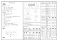
Instruction manual and data sheet Torque Sensor Series 2000SENSORES E INSTRUMENTACION GUEMISA S.L.()N.I.F.: B-87969416C\ De la Fundición 4 Bis - Planta 1ºOficina-228522 Rivas Vaciamadrid (Madrid)Telf. 91 764 21 00******************Copyright ©NCTE AG® Torque Sensor Series 2000 Instruction Manual and Data Sheet. This instruction manual is property of NCTE AG®,D-82041 OberhachingUnauthorized duplication, even in part, is not permitted.State: December 2020Instruction manual1 General (5)1.1 Customer service address (5)1.2 Warranty (5)1.3 Scope of delivery (5)1.4 Declaration of conformity (6)2 Safety (7)2.1 Intended use (7)2.2 Recalibration and duration of use (7)2.3 Structural change (7)2.4 Training of the operating personnel (7)2.5 Transport and handling (7)3 Torque Sensor Series 2000 (8)3.1 Short description (8)3.2 Assembly and disassembly (8)3.3 Interface description (8)3.4 Starting up (8)3.5 Operation during regular mode (9)3.6 Irregular operation, actions in case of failures (9)3.7 Safety instructions (9)3.8 Shaft preservation (9)3.9 Service, maintenance and repair (9)3.10 Disposal (9)Data sheet1 Key Facts (10)2 Torque ranges (10)3 Load characteristics (11)4 Technical characteristics (11)5 EMV Emission data (12)6 Dimensions (13)7 Wiring diagram (14)8 Sensor wiring (14)9 Order options (14)10 Accessories (15)Instruction manual.1GeneralDear customers,Thank you for your decision to buy our sensor products. You have chosen a high quality and extremely precise torque measuring system.This manual contains all the information necessary for you and the installation, operating and maintenance personnel to use your measuring system under the intended conditions of use. It contains important information to ensure proper and safe installation and operation.For these reasons, the Instruction manual must always be available at the place of use of the torque measuring system and always ready to hand.We reserve the right to make changes in the course of product improvements. We try to maintain compatibility with previous versions. All information without guarantee subject to technical changes.For further questions, we are of course also available after the purchase at any time.Please use our contact address1.1Customer service addressNCTE AGRaiffeisenalle 3D-82041 OberhachingPhone: +49 (0)89 665 619 0Email: *************Web: https:///1.2WarrantyThe warranty period is 12 months from the date of delivery from the factory, provided that the product is used in accordance with its intended purpose, in compliance with the maintenance and calibration regulations and the General Terms and Conditions of Business.You can find these, current instruction manuals and data sheets on:https:///en/standard-products/#1.3Scope of deliveryThe torque sensor system consists of a calibrated sensor, signal acquisition / -processing integrated in the housing, a 5 m long connection cable with plug (Binder plug no. 99-0426-10-08) and keystone (round shaft) or square sleeve (square shaft).Enclosed you will find the corresponding calibration certificate and the warning notes.1.4Declaration of conformityThe manufacturerNCTE AGRaiffeisenalle 3D-82041 Oberhachinghereby declares that the following productProduct designation: Torque sensor series 2000Trade designation: Series 2000Model names: 2100-2.5 2200-2.52100-5 2200-52100-7.5 2200-7.52100-15 2200-17.52100-60 2200-752100-140 2200-1752200-2502100-400 2200-500conforms to the requirements of the EMC Directive 2014/30/EU – including its amendments in force at the time of this declaration.The following harmonized standards were applied:EN 61000-6-2:2019-11EN 61000-6-4:2020-09EN 61326-1:2013-07EN 61326-1:2018-09 (Draft)The following national laws, standards and specifications were applied:Electromagnetic compatibility law – EMVGPlace: OberhachingDate: December 15th 2020______________________________ ______________________________Dr. Jürgen Uebbing, CEO Ms. Verena Graf, COO______________________________Mr. Bernhard Mayr, Technical Director2SafetyPlease note the enclosed sheet on the warning notes.2.1Intended useThe sensors of the series 2000 are designed exclusively for measuring torque and/or speed. The respective load range can be taken from the data sheet and must not be exceeded.Proper use also includes compliance with the commissioning, assembly, operating, ambient and maintenance conditions specified by the manufacturer.Any use beyond these is considered improper. The manufacturer is not liable for any damage resulting from such use.2.2Recalibration and duration of useA factory recalibration should be executed annually. See the corresponding label on the sensor.This recalibration can be carried out quickly and easily by NCTE AG.Please contact us.If the sensor is used within the limits of its intended use and regularly calibrated, the sensor's operating life is unlimited.2.3Structural changeUnauthorized conversions or changes to the torque measuring system are prohibited for safety reasons and lead to the immediate expiration of the warranty claims.2.4Training of the operating personnelAssembly, commissioning and maintenance personnel must have read and understood the complete operating instructions, especially Chapter “2 Safety". The operator is recommended to have this confirmed in writing.2.5Transport and handlingDuring handling, storage and transport, make sure that the sensor is not exposed to strong magnetic or electromagnetic fields (e.g. degaussing coils).3Torque Sensor Series 2000The Series 2000 provides the easiest and most cost-effective entry into torque measurement technology.3.1Short descriptionThe series is mainly used in test stands, automation processes, production lines e.g. end-of-line tests and teaching.Torque measurement is possible both statically and dynamically. The mechanical connection is made via a square shaft (series 2100) or round shaft (series 2200).The Series 2000 provides an analogue output signal with 0-5V.The sensor is delivered as a ready-to-connect unit including 5m cable, keystones (round shaft) and calibration certificate.3.2Assembly and disassemblyWhen mounting the sensor, make sure that the measuring shaft is exactly aligned with the connecting shafts (corresponding couplings can be found in the accessories). It must then be possible to push the key adapters / square ends of the connection shafts onto the key adapter connections / square connections of the sensor without any effort. No force must be exerted on the housing in the axial direction during fastening. The sensor can be secured against rotation by means of the flat surface (optional sensor holder). The cable length must not exceed 5m. Using a cable other than the one supplied by NCTE or an identical cable with a different cable length may impair the function of the sensor system.The disassembly may only be done without applying torque to the measuring shaft.3.3Interface descriptionMechanical interfaces:For power transmission, adapter connections are provided at both ends of the keystone round shafts. In respect to square sensors, the shaft has square ends.Electrical interface:A socket for power supply and signal output is attached to the upper side of the housing.(Pin assignment see Chapter “7 Wiring diagram")3.4Starting upAfter mounting the sensor, the following must be observed:∙Switch on power supply and check voltage value.(Voltage peaks at the sensor must be avoided, devices must be checked accordingly beforeconnection to the sensor)∙Connect the sensor to the power supply. (using the cable supplied).∙Record the output signal of the sensor with high resistance.(e.g. A/D converter, oscilloscope, PC measuring card)∙Record output signal in mechanically unloaded state of the sensor.3.5Operation during regular modeOptimal measuring values are achieved when the sensor is used while maintaining the specific nominal torque. If the permissible operating conditions are observed, the sensor operates trouble-free and maintenance-free.3.6Irregular operation, actions in case of failuresIf the sensor is mechanically overloaded (e.g. if the maximum permissible longitudinal force or torque limit is exceeded or if there are strong vibrations), the sensor may be damaged and the signal output may be distorted. In this case do not open the device. Contact NCTE AG directly.3.7Safety instructionsThe following safety instructions should be followed for smooth operation:∙Opening the sensor or even single screws is not allowed.∙The shaft retaining rings on the shaft ends must not be loosened.∙The fastening nut of the plug must not be loosened or tightened.∙Only use power supplies safely disconnected from the mains voltage.∙Regarding the electrical and mechanical load of the sensor, the specifications according to the sensor-specific nameplate and the table in Chapter “4 Technical characteristics” must be observed.∙The sensor is not to be used as support bearing. The existing fastening options serve exclusively to secure the housing against twisting.∙To protect your system, we recommend increasing the torque over several stages.3.8Shaft preservationThe shafts are protected on both sides with a film of anti-corrosion wax. We recommend to leave the protection permanently. If technically necessary, remove the protective film with spirit/ethanol.3.9Service, maintenance and repairAs part of your test and measurement equipment management, we recommend regular inspection of your test and measurement equipment. Please also observe the relevant standards and guidelines. Maintenance plan by NCTE AGCalibration: Every 12 monthsCheck the wiring, connectors and shaft: Every 12 monthsRepairs and recalibrations can only be carried out by NCTE AG personnel.3.10DisposalThe device must be returned to NCTE AG, Raiffeisenallee 3, D-82041 Oberhaching for disposal.Data sheet. 1Key Facts2Torque rangesNote: Series 2100 sensor versions are calibrated to nominal torque. However, the absolute operating limits are as shown in the table above. Do not exceed the specified magnitude of the limit torques for unidirectional and bidirectional loading.Note: In case of overload, the sensor leads to a measurement offset. In this case the sensor must be recalibrated at NCTE AG. The sensor may only be operated within the specified nominal torque range.3Load characteristicsAny irregular stress (bending moment, transverse or axial force, exceeding the nominal torque) up to the specified static load limit is only permissible as long as none of the other stresses can occur. Otherwise the limit values must be reduced. If 30 % of the limit bending moment and 30 % of the limit transverse force are present in each case, only 40 % of the axial force is permissible, whereby the nominal torque must not be exceeded.4Technical characteristics1 Specified values only apply to direct axial force on the shaft. If the axial force acts on the circlip, only 50 % of the force is permissible.2 Specified values only apply to direct axial force on the shaft. If the axial force acts on the circlip, only 50 % of the force is permissible.3The accuracy class means that the linearity deviation as well as the circulation modulation, individually, are each less than or equal to the value specified as the accuracy class. The accuracy class must not be confused with a classification according to DIN 51309 or EA-10/14.4 %ME: Related to the measuring range.5 The exact sensor-specific values can be found in the calibration certificate supplied.EMV immunity and emitted interference (DIN EN IEC 61000-6-2 / DIN EN IEC 61000-6-4 / DIN EN 61326-1)6 Wiring connected.6 DimensionsSeries 2200For high alternating loads, torque transmission by positive and frictional locking via a suitable fit or couplingis recommended.2200 (TM-HR-Rd)Round drive2100 (TM-HR-Sq)Square drivePotentiometer for offset adjustmentKeystone7 Wiring diagramConnectorPower supply and outputs8 Sensor wiringThe grey and blue wires are not required.The blue wire is not required.9 Order optionsWe would be pleased to provide you with further information about serial products in a personal contact underPhone: +49 (0)89 66 56 19 30 or by e-mail: *************.10AccessoriesBracket1 2.5 – 17.5 Nm (Art. No.: 400006081)2 75 – 250 Nm (Art. No.: 400006082)Readout unit1 Order number 400010-ATS001 The NCTE readout unit is a multifunctional readout unit fora USB interface.Couplingscoupling types Used for D2 max.You can obtain further or additional accessories and special requests in a personal discussion with your contact person for series products by calling +49 (0)89 66 56 19 30 or by e-mail: *************.Your experts for magnetostrictive sensorsSENSORES E INSTRUMENTACION GUEMISA S.L.C\ La Fundición 4 Bis - P 1Oficina-2l ª28522 Rivas Vaciamadrid (Madrid)Telf. 91 764 21 00 email:******************。
扭矩功率测试仪使用说明书A3
取值范围 1~9999
说明 5.1 5.1 5.1 5.1 5.1 5.1 5.1 5.1 5.1 5.1 5.1
1~4(注 2)
0~4(注 2)
100~10000 1 0~9999 0.5000~1.5000 1~20 3~30 1~20 1~20
后端子图
AFH 1 - -15V 2 - GND 3 - +15V 4 - 转速 5 - 扭矩 oYt At in-A Fi FLtr
二、安装与接线 1 外形图
地址 50H 51H 52H 53H 54H 55H 56H 57H 58H 报警方式 , .
取值范围 0~3 0~23 0~59 0~59 0~99 1~12 1~31 0~23 0~59 , . ,
说明 5.6 5.6 5.6 5.6 5.6 5.6 5.6 5.6 5.6 .
扭矩功率测试仪使用说明书
一、技术规格 1 基本技术规格 K 型小台式,尺寸:216×90×280 仪表电源:220VAC 显示范围: 扭矩显示:-19999~19999,小数点位置可设定 转速显示:-1999~4500,小数点位置可设定 功率显示:0~9999,小数点自动调节 脉冲输入信号:各种 NPN、PNP、OC 门输出的接近开关,旋转编码器 计数频率: 2 选配件技术规格 报警输出 2 种报警方式,通过设定选择。延时报警功能 继电器输出:触点容量 220V AC,3A
90
符号
名称 PLuA in-d in2d Lc
内容 转速 1 个计量单 位对应脉冲数 转速显示小数点 位置 扭矩显示小数点 位置 扭矩的量程范围 转速计量单位 转速零点修正 转速量程修正 转速数定滤波时 间常数
扭矩扳手校准仪的操作如何

扭矩扳手校准仪的操作如何扭矩扳手是一种关键工具,可以帮助确保机器和设备的各种部件和连接件得到正确的扭矩值。
扭矩值是在设计阶段就已经确定的,是使设备和机器正常工作的关键。
因此,扭矩扳手的准确性非常重要。
但由于长期使用或不正当的使用,扭矩扳手的准确性可能会有所下降。
如果扭矩扳手不能成功地校准,那么就必须将其送到专业的维修机构进行校准。
然而,通过扭矩扳手校准仪,您可以完全自行校准扭矩扳手,以确保其准确性。
使用扭矩扳手校准仪的准备工作扭矩扳手校准仪需要以下准备工作:•选择适当的工作台/工作区域,确保准备好所需的工具和设备,如扭矩扳手和校准程序。
•准备好校准手册/工具,它们应向您提供所需的信息,例如校准扭矩扳手的规范等。
•做好校准仪的清洁工作。
每次使用校准仪之前,请确保其外表面,内部组件和配件均非常干净。
开始进行扭矩扳手的校准以下是进行扭矩扳手校准的步骤:第一步: 加力将您的扭矩扳手插入校准装置中,并确保将其稳定地固定在适当的位置。
然后请按照校准手册上给出的顺序逐步进行操作。
首先需要施加一定的力量,通常为50%的最大力矩值。
第二步: 记录读数在扭矩扳手施加50%最大力矩值时,请记录读数。
通常,您需要使扭矩扳手达到指定的读数值。
如果扭矩扳手未达到要求的读数,您需要进行手动调整,直到其达到指定的读数。
第三步: 增加施加力量接下来,请进一步增加施加的力量,通常要达到扭矩扳手最大的力矩值。
这通常需要先减小误差,确定准确的读数。
然后更新您的记录,并确保读数达到规定的要求。
第四步: 重新校准如果您发现您的读数和规定的值有较大差异,请重新校准。
在重新校准之前,请检查校准表格上的标准值,以确保您的读数是正确的。
第五步: 整理文件完成校准后,请整理好所有校准资料,并存档。
这将让您在需要时能够更轻松地回顾及追溯资料。
总结以上是校准扭矩扳手所需的步骤。
您需要确保在此过程中遵循所有操作要求以确保安全性。
如果您对使用扭矩扳手校准仪仍有疑惑,请寻求专业的帮助。
2000标准负荷测量仪仪表说明书

本手册主要介绍2000标准负荷(扭矩)测量仪的连线、校准、设置和使用方法,请用户在使用前仔细阅读。
一、2000标准负荷测量仪简介2000标准负荷(扭矩)系列测量仪是一款经过10年大量实践检验被最广泛认知的基础力学测量仪器,10年来先进的测量器具在基础力学测量领域中的推广应用和称重传感器在性能、质量、产能以及在世界市场上份额的增加,该系列仪器有着不可磨灭的贡献,应用领域包括:精密力值测量;扭矩测量、材料性能测试、应力应变测量、峰值测量以及基于应变原理传感器的生产检测领域。
相关的产品更新信息请参阅第3页。
2000A型仪表为最常用的测力计配套仪表,具有很高的可靠性和性能价格比,6或40个数据通道,额定显示分度5万,重复性、线性<0.01%FS,AD转换速率50~500次/秒,mV/V量值准确度:0.030%+0.020%(准确度采用相对于读数+相对于量程的不确定度描述方法,以下同),温度系数:<20ppm+10ppm,该款仪表主要应用于当量准确度为0.3%的标准测力计和常规力值测量。
2000B型仪表提供更高的准确度和测量效率,适用于当量准确度为0.1%的标准测力计、标准叠加式测力机和高要求测量需求,6或40个数据通道,显示分度20万,重复性、线性<0.005%FS,mV/V量值准确度:0.015%+0.010%,温度系数:<10ppm+5ppm。
2000D型仪表为扭矩测量仪表,6或40个数据通道,额定显示分度5万,重复性、线性<0.01%FS,AD转换速率50次/秒~500次/秒,mV/V量值准确度:0.030%+0.020%,温度系数:<20ppm+10ppm。
2000E型仪表为应变式传感器检测、补偿和调整的专用仪表,可直接显示传感器输出信号mV/V的测量值,信号输入范围:-12mV/V~+12mV/V,最小分辨率:0.01 V/V(等效于6.5位数字电压表),重复性、线性<0.005%FS,mV/V量值准确度:0.015%+0.010%,温度系数:10ppm+5ppm,内置传感器供桥电源,可替代“稳压电源+数字万用表”的传感器检测、补偿和调整方法。
扭矩扳子检定仪使用要领书范本 图文

图2 会签(日期)
标记
处数
更改文件号 签字
日期
制式
标准化(日期)
审定(日期)
***有限公司
计量检测(设备)器具使用要领书
操 作内容 一、使用前 1、根据扭矩扳子规格选用合适量程的扭矩扳子检定仪,并检查 扭矩扳子检定仪合格证是否在有效期内,见图1; 2、将被检扭矩扳子的方榫或转换器插入检定仪套筒内,通过扭 矩扳子棘轮头调整扭矩扳子位置使其刚带载荷时位置与加载板 平行,见图1; 3、松开立杆组件侧面的旋钮,调节立杆组件位置使其位于扭矩 扳子手柄施力点(即加力刻线,无加力刻线的使其位于手柄两 端中线位置),然后紧固旋钮,见图1;
6、卸载时逆时针旋转手轮直至扭矩扳子手柄与立杆组件分离;
7、按一下“复位”键,即可进行下一轮测量。合格证 开关 Nhomakorabea手轮
图1
描校 三、使用后
描 图 1、按二、6条要求进行卸载; 2、关闭检定仪电源开关;
底图号 3、取下扭矩扳子和转换器,并进行定置、平稳放置。
装订号
设计(日期)
跟踪/保持
复位键手轮
校对(日期)
3、按“复位”键,检定仪显示“0.0”,见图2;
4、按“制式”键,选用扭矩单位“N.m”(红灯亮),见图2;
5、施力前按“复位”键,检定仪显示“0.0”后,顺时针转动 手轮进行测量,定值扳子发出“咔”声响时或指针式扳子指示 到校准点时读出检定仪显示值;
1.施力均匀平稳,不得中途停留 2.校正3次,取最大值进行评判 3.若扭矩扳子不合格则按不合格计 量器具处理程序处理
要求
使用部门
计量检测(设备)器具名称 NJ型扭矩扳子检定仪
T.16计量-0103 共 1 页第 1 页
- 1、下载文档前请自行甄别文档内容的完整性,平台不提供额外的编辑、内容补充、找答案等附加服务。
- 2、"仅部分预览"的文档,不可在线预览部分如存在完整性等问题,可反馈申请退款(可完整预览的文档不适用该条件!)。
- 3、如文档侵犯您的权益,请联系客服反馈,我们会尽快为您处理(人工客服工作时间:9:00-18:30)。
DMP2000扭矩扳子检定仪(手动)软件使用说明书
中国航空工业集团公司
北京长城计量测试技术研究所
扭矩扳子检定系统使用说明书
一、概述
本扭矩扳手检定系统是由国防科技工业第一计量测试中心研制开发的检定扭矩扳手的专用软件,该软件配套DMP2000型扭矩仪表、扭矩手动加力工作台。
具有采样速度快,精度高,加载方便等特点,特别适于各计量站、室检定扭矩扳手使用。
二、安装说明
1.使用范围
1)本设置使用说明应用在更换电脑主机、电脑重装系统等情况。
2)本方法适用于Windows XP系统。
2.操作方法
1)如果上位机其串口是默认为COM10,无需修改。
2)如果上位机没有串口,则启动电脑后,将USB--串口线的USB口插入电脑,然后将驱动
光盘放入,系统提示发现新硬件,选择自动安装驱动程序(全部选择自动安装,“下一步”
即可)。
3)安装结束后,进入我的电脑——管理——设备管理器——端口,查看“USB-SERIAL”是
否为COM10,如果“是”直接进入步骤(4),如果不是则说明COM10已存在,请右键COM
——属性——端口设置——高级,左下角将其设置为其他串口号,然后再右键
“USB-SERIAL”——属性——端口设置——高级,左下角将其设置为“COM10”。
4)硬件设置完成,安装软件即可使用。
运行安装程序:“扭矩扳子检定软件.exe”,选择安装目录,点击下一步,直至安装完成。
三、使用说明
3-1、接通仪器电源,接通传感器,开机预热15分钟,然后打开电脑。
3-2、用数据线连接DMP2000仪表与计算机。
3-3、启动软件系统
启动校准软件即可进入程序主界面,如图1所示
图1 程序主界面
3-4、扳手的检定:
1)在参数控制栏(图2所示)中填写相关信息。
出厂编号、温度、湿度等信息请直接输入,
送检单位、型号规格、制造厂、标准器等信息可直接输入,也可从列表中选择。
添加列表信
息方法见3-5.
2)在数据区(图3)中“检定点”栏中输入需要检定的扭矩值。
图3 数据区
3)按照扳手量程选择传感器,并调整仪表通道和系数。
4)仪表单位选择为Nm,如果需要其他单位,请在界面上选择,软件会将Nm自动换算成
指定单位。
图4 单位选择框
5)检定定值扳手时,鼠标单击“正矩检定”或“反矩检定”,焦点框变为蓝色,驱动加载装
置,扳手加载,达到预设值后,卸载扳手,检定过程中的最大值自动记入电脑,焦点框变为白色。
扳手完全卸载后,焦点框自动移动至下一记录框,并变为蓝色,继续驱动加载装置,完成下一个检定点的检定。
如果扳手完全卸载后,并未达到零点,则焦点框不会移动到下一记录框,此时需要按仪表上的“清零”键,则下一记录框变为蓝色的焦点框,驱动扳手加载即可。
只有出现蓝色焦点框后,才能驱动加载装置加载。
图5 检定状态示意图
6)检定非定值扳手时,驱动加载装置,加载扳手,达到预定值之后,双击上图列表中的相
关单元格,可将仪表显示值采集进电脑;
7)按照检定点逐点进行测量,直至完成测量,系统按照规程要求自动进行数据处理,判定
扳手级别。
如果已测个别数据不理想,可参照步骤(6)进行操作,用鼠标将仪表储存的“大值”采集进电脑即可。
3-5参数设定
在“工具”菜单中可以完成系统参数的送检单位、型号规格、制造厂、标准仪器等进行增删管理、设定等项目。
如图7所示;
图7 工具栏选项
图8 标准器信息填写
四、注意事项
1、本软件为专业人员使用,非扭矩计量人员禁止操作。
2、安装目录下的“测试记录”文件夹为系统指定的测试记录存储路径,请对其下数据做定期备份。
3、软件系统若出现故障,请重新安装并重启计算机,若故障仍未排除,请联系生产厂家。
五、关于如何修改模版
鉴于用户的模板不一致,或者有时需要更改,为此下面列出自己修改模板的步骤。
首先要确保WORD文件中重要信息部分不要使用自选图形格式中插入文字的方式。
1.打开安装文件目录的data文件夹下打开原始模版,data文件夹下包含
模版,“原始记录模版.doc”,文件“test.txt”不需要任何修改。
2.打开模板,在模版中可以看到需要填写的信息的地方都用一些代码填
写了。
3.打开模版采用的新文件
4.在新文件中需要填写信息的地方用原始模版中相应的代码代替,诸如:送检单位:SJDW
型号规格:Xhgg
出厂编号:ccbh
……………..等等。
5.所有信息填入后,在模版所在文件夹下(如data文件夹)删除原模版
文件,将新的文件修改为需要替换的原模版的名字。
大功告成啦!!。