海尔大神童xq880-m208洗衣机说明书
海尔电子科技有限公司洗衣机用户指南说明书

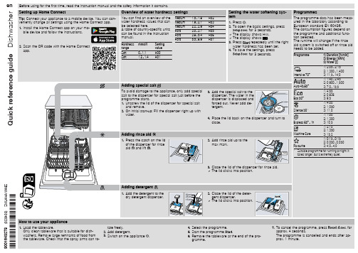
6. Clean the filter. 7. Re-insert the filter in the supply hose. 8. Screw the water connection back on. 9. Check the water connection for leaks. 10.Restore the power supply. 11.Switch the appliance on.
of the impeller.
7. Insert the pump cover and press
down .
2
a The pump cover clicks into position.
1
8. Install the filter system.
Troubleshooting
Fault
E:32-00 will light up alternately or indicator for water supply lights up.
and remove. 2. On initial start-up: Fill the dispenser right up with
water.
Adding rinse aid
1. Press the catch on the lid
of the dispenser for rinse
2
aid and lift .
Cause and troubleshooting
Supply hose is kinked. ▶ Install the supply hose without kinks.
Water tap is turned off. ▶ Turn on the water tap.
洗衣机使用说明书

洗衣机使用说明书(总9页)--本页仅作为文档封面,使用时请直接删除即可----内页可以根据需求调整合适字体及大小--1.使用前须知连接进水管1.选择适合的水龙头(前段长度必须大于10mm,若水龙头出口端面不平整,请用锉刀锉平,以免漏水)2.取下进水管接头①②③④①按住锁紧杆下端;②握住进水管,向下压滑动器,取下进水管接头;③接下标记牌。
3.安装进水管接头①拧动螺母,露出3至4圈螺纹;②将进水管接头的四颗螺钉拧松至可将进水管接头套在水龙头上;③如果进水管水龙头无法套在水龙头上,请取下衬套在安装;④将其中一个螺钉事先旋到大致适合位置,在将进水管套在水龙头上,将其余三颗螺钉均匀拧紧,确认到位后,旋紧螺母。
4.连接进水管①压下滑动器,将水管插入进水管接头;②用锁紧杆挂住水管接头,然后松开滑动器,直到听到“啪”的一声。
5.连接洗衣机①将进水管另一端的螺母套到进水阀接头上;②拧紧进水管螺母并确认螺母紧固到位。
6.检查进水管是否连接好①检查连接是否牢固;②安装完毕后,打开水龙头,检查是否漏水;③每次使用洗衣机前,请检查确认进水管与水龙头连接牢靠④切勿强力弯曲进水管。
粘贴毛毡,安装降噪板1.将毛毡粘贴在降噪板的一侧。
2.将洗衣机向后倾斜,卸下四个底脚。
3.降噪板附有毛毡的一面朝内,将将底脚螺栓穿过四个孔装在壳体上旋紧,重新放平机器。
排水管排水管出水端高度必须大于80cm,最高点必须小于100cm,为防止排水管脱落,可将排水管固定在机器后的排水管卡上或使用排水支架固定,建议不要加长排水管,加长部分若超过,易出现边进水边排水现象。
延长排水管,请联系本公司售后服务部门。
调整底脚使用之前应先调节四个底脚,使洗衣机处于平衡状态。
底脚调节完毕后,要把底脚支撑螺母旋至紧贴壳体位置处,以支撑洗衣机。
分配器盒(每次只放入一次洗涤所需的洗涤剂)预洗洗涤剂投入室主洗洗涤剂投入室软化剂,漂白剂投入室选择预洗的功能时,在预洗室投入洗涤剂预先洗涤衣物;洗涤剂的用量请参照洗涤剂的使用说明,过量的洗涤剂会产生大量泡沫,易溢出,且影响洗涤剂的溶解;应使用滚筒洗衣机专用低泡洗涤剂,若洗涤合成或羊毛织物时,则应该用为其特制得洗涤剂软化剂或漂白剂的最高液面不要超过分配器盒的MAX标识。
海尔洗衣机用户手册.pdf_1702095214.4677227说明书

lights (DRL)
PPooT(TwiwrPeMeePrrSr)ettsaasiiullggreaattMeeonitoring System
LLaannee DDVSeeAppOaarrFttFuurree WWaarrnniinngg ((LLDDWW))
Tur
On/Off Indicators Condition IndicaPPtooorwwseerr sslliiddiinngg ddoooorr
NEW STYLE 5/1/2013 7:27 AM PagIIeNN4SSTTRRUUMMEENNTT PPAANNEELL IINNDDIICCAATTOORRSS
Briefly appear with each engine start. Red and amber indicators are most critical. Blue
High beams on
T(T(FTTiuirrPPeeeMMl PPeSSErrc))xeeotssenssriouuormrreeliygMMhotosononnniittoorriinngg SSyysstteemm
CRU CRU
OFF (lRoecafitlel d on center panel)
AAFnnCttW ii--LLLAooo(dcwcbdkklitnaiBrBkierrrspa)a:rkkeeessuSSryyess:tteemm ((AABBSS))
Ma Ma
traint
System
Briefly
LLCooVlwewohsicbbelerraadSkktoaeeboiflfilrltuuy(iiAsdd)s,,s/bbtisarrt®aailk(kgVeeSaAssty)yesstteemm Seat belt reminder: appLLFeooBaawrwrsatkwoeoeiiinotllhvppesrrerereeaiadsscetsshuusbyrerseentelgmti(nse) start. Red
海尔电子科技有限公司洗衣机用户手册说明书
of the impeller.
7. Insert the pump cover and press
down .
2
a The pump cover clicks into position.
1
8. Install the filter system.
Troubleshooting
Fault
E:32-00 will light up alternately or indicator for water supply lights up.
6. Re-assemble the filter system.
7. Insert the filter system into the appliance and turn the coarse filter clockwise. Make sure that the arrow markings match up.
Cause and troubleshooting
Supply hose is kinked. ▶ Install the supply hose without kinks.
Water tap is turned off. ▶ Turn on the water tap.
Water tap is jammed or furred up. ▶ Turn on the water tap.
1) 0:15 - 0:15 2) 0,050 - 0,050 3) 4,0 - 4,0
1 Suitable programme for running at night: it takes longer, but is extremely quiet.
1
海尔洗衣机用户手册说明书

12 1-25503A
SCREW TSEI
13 1-11533
HEX NUT
14 EAC0100G63A
PLASTIC COVER ASSY M2
15 1-22323A
SELF-TAPPING SCREW
16 1-9841
WASHER,PLAIN d6 ZINC.
17 1-9641
WASHER
Désignation
1
X
M12X35 8.8 A2J
1
X
SONAR VERSION
1
X
COBERT. INF. GRUPO MIS. TORNILLO AUTORR. Transformador 100/230V Transformador Transformador 230/230V Transformador 100/230V TAPÓN CASQUETE NEGRO TORNILLOS M5
1 EAA0263G07A
J-TYPE BRAKE PEDAL
1 EAA0372G98A
ALU BRAKE PEDAL 2 SWICTHES
2 EAC0060G00A
VIBRATORY SYSTEM HOLES CUP
3 EAC0060G02A
FLANGES PROTECTION
4 EAM0006G01A
LCBS-2-6-01 3
Entretoise
Distanciador
,M4X10 M/F 1
VIS CB RONDELLE
Tornillo ARANDELA
M4 x 6 1
UNI 7687
Ø 4,2 1
X
X
X
X
全自动滚筒洗衣机说明书
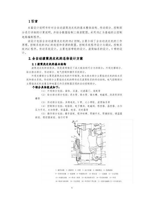
1引言本篇设计说明书针对全自动滚筒洗衣机的基本整体结构、传动部分、控制部分进行详细的计算说明,并结合数据绘制三维装配图。
采用PLC为基础的主控制电路编制程序。
该设计包括全自动滚筒洗衣机的PLC控制,主要介绍了全自动洗衣机的工作原理,控制系统的PLC的选型和资源的配置,控制系统程序设计与调试,控制系统PLC程序。
传动系统设计,主要包括带轮的设计,滚筒轴系的设计,V带的设计。
2.全自动滚筒洗衣机的总体设计方案2.1滚筒洗衣机的基本结构滚筒洗衣机种类很多,但是通常情况下其大致结构可分为四部分:外观支撑部分、给水排水部分、传动部分、电气控制和操作系统部分。
外观支撑部分主要是滚筒洗衣机的外形框架,给水排水部分主要指洗衣机的给水系统和排水系统,传动部分主要指洗衣机的带传动及滚筒轮系的传动结构,电气控制部分主要指洗衣机依靠各种电器元件及控制器实现的自动控制部分。
个部分具体组成如下:(1)外观部分包括:箱体、后盖、过滤器门、底板等(2)给水排水部分包括:进水管、排水管、储水槽、电磁阀、洗涤剂回收槽等(3)传动部分包括:多频电机、V带、大小带轮、滚筒轴系等(4)控制部分包括:电脑版、电子模块、电磁阀、程控器、温控器、水位压力开关、水加热管、恒温器、电容、定时器等(5)操作部分包括:操作面板、程序标牌、琴键开关、琴键按钮、调温器旋钮、程控器旋钮、指示灯等2.2滚筒洗衣机各部分的设计方案2.2.1主体部分洗涤部分主要由内筒(不锈钢滚筒)、外筒(盛洗涤液用,又称盛水桶)、内筒叉形架、转轴、外筒叉形架、滚动轴承等组成。
(1)内筒及内筒叉形架内筒又称滚筒。
滚筒是滚筒式洗衣机对衣物进行洗涤,洗涤效果有着直接关系。
内筒用厚度为2-3毫米的抛光不锈钢板卷制而成的。
有直径为3.5-5毫米的圆孔,孔与孔之间的距离大约为15-20毫米。
圆孔自内向外冲刷,翻边向外,内壁光滑,以防洗涤时刮伤衣物。
在滚筒内壁沿轴向有三条凸筋,这三条凸筋在洗涤过程中起举升织物的作用。
海尔电器洗衣机用户手册说明书
50 ml
2. Close the lid of the deter-
25 ml
gent dispenser.
15 ml
a The lid clicks into position.
9001627208 (020404) SMV4HVX38G
*9001627208*
How to use your appliance
and remove. 2. On initial start-up: Fill the dispenser right up with
water.
Adding rinse aid
1. Press the catch on the lid
of the dispenser for rinse
2
aid and lift .
7. To cancel the programme, press
for
approx. 4 seconds.
The programme is cancelled and ends after ap-
prox. 1 minute.
Cleaning filters
1. After each wash check the filters for
1) 1:40 - 2:45 2) 0,850 - 1,450 3) 7,0 - 15,5
1) 5:20 2) 0,836 3) 9,5
1) 1:40 - 1:45 2) 0,750 - 0,800 3) 11,5 - 14,0
1) 1:00 2) 1,200 3) 10,0
1) 2:10 2) 1,350 3) 15,1
Adding special salt
海尔家电产品说明书
SuperPole™SuperBar™SuperTrapeze™SP-S SP-HDSPB-SSPB-HDSPB-AK(DC100 - RevE)STP-SSTP-AK89111012131457346212HW318HW323HW302202122232829301724252726182315181917163HW100SP102HW320HW300HW320HW112+++SP-SSPB-SSTP-SSP-SSPB-SSTP-SSP-HDSPB-HD12345 678910 42"/51mm6"/154mm3"/76mm10"/254mm ABC D EABCEDFACEBD45612351234 56 6HW318HW323HW30278910+(2-5)111271234HW100 56889101112HW100984"2134mm3+4567101289101111Ø 5" / 127mm 20"508mm93-99"2362-2515mm2.50" / 64mm1.0625" / 27mm8"203mm20"508mmØ 1.50" / 38.1mmFE / PVC / UHMW SP-P 13lbs / 5.9kgFE / NBR SP4034lbs / 1.8kgFE / NBR SP4021lbs / 0.4kg1216"406mm8"203mmØ 2.50"64mmØ 2"51mmØ 1.50"38.1mm3.875"98mm17"432mm8"203mm3-29"76-737mm12.25"311mm13.5"343mmPOMFEFE / PA / LDPE FE / PVC SP102.05lbs / .02kgFE / PVC SP4044.20lbs / 1.91kgSP4085.25lbs / 2.38kgSP411.85lbs / .39kgSP4092.05lbs / .93kgSUPERPOLE (SP-S)93-99"2362-2515mm 93-99"2362-2515mm 100-120"2540-3048mm 121-140"3073-3556mm < 93"2362mmSUPERBAR300lbs / 136kg450lbs / 205kg 300lbs / 136kg 300lbs / 136kg 300lbs / 136kgMAXANGLED CEILING PLATEUNI-FIT EXTENDERCEILING PLATE EXTENDERSUPER-TRAPEZESUPERPOLE HEAVY DUTY (SP-HD)UNI-FITEXTENDER (SP-UF)SUPERPOLEULTRA (SP-ULTRA)SUPERPOLE CUSTOM (SP-CUSTOM)SUPERPOLE CEILING PLATE EXTENDER (SP-CPE)SUPERPOLE ANGLED CEILING PLATE (SP-ACP)13OVERVIEWThank you for choosing the SuperPole System from HealthCraft. Please read and understand the instructions in this manual; keep manual for future reference. It is your responsibility to see that your SuperPole System is properly assembled, installed, and cared for. Failure to follow instructions in this manual could result in serious injury or death. If you are not equipped to undertake the outlined work, we would recommend that you have your SuperPole System installed by a qualified contractor.The SuperPole System is intended for moderate vertical load bearing to provide sitting and standing support for people with reduced mobility. The floor to ceiling range and maximum user weight dependent on model (see Page 13 for details and product / accessory compatibility chart). Product is not intended to support full body weight. The SuperPole System is not to be used in any other way than described above.The SuperPole is a high quality, commercial grade floor to ceiling safety pole. The SuperPole must be installed between a structural floor and ceiling by turning a jackscrew at the bottom of the pole. The pressure created by the jackscrew is strong enough for the SuperPole to support the user, yet it does not require drilling holes into the floor or ceiling. This is ideal for relocating or removing the pole. NOTE: The top plate has two holes that may be used to fix the plate directly to the ceiling joist if necessary. See Page 4 for details.The SuperBar is a high quality, commercial grade pivoting and locking horizontal bar that connects to the SuperPole (floor to ceiling safety pole). The horizontal bar can be lifted, pivoted and lowered to the next locking position around the SuperPole. In any of the 8 lowered position (every 45 degrees) the SuperBar can be used to support the user. It is important to set proper height and orientation of the SuperBar to optimize the user’s range of motion.The SuperTrapeze is a high quality, commercial grade over-bed trapeze that connects to the SuperPole (floor to ceiling safety pole). The SuperTrapeze handle features two offset ladder rungs to allow for improved use of arm strength and increased comfort. Additionally, it can hook around the pole to store out of the way when not in use. The support arm has an adjustable strap that attaches to the trapeze handle. It is important to set proper height and orientation of the SuperTrapeze to optimize the user’s range of motion.WARNING - PATIENT ENTRAPMENT (see additional guidelines)The potential risk of entrapment (limb, neck, head, torso) between the pole and adjacent item (i.e. bed, toilet, etc.) can be reduced or avoided by the following strategies:1. Situate the pole at a distance that is considerably smaller or larger than that which could result in entrapment.2. Consider situations that could change with time or usage such as mattress compression, patient movement, bed position changes due to electrically powered beds, etc.3. Realize that this product is not intended as a physical constraint or barrier to exiting the bed.LIMITED LIFETIME WARRANTYProducts are covered by a limited lifetime warranty against defects in materials and workmanship for the original purchaser. Warranty excludes products that have been damaged through misuse, accidental damage, alteration, normal wear and tear, wood material and stain, or the use of corrosive or abrasive cleaning products.Buyer hereby indemnifies, agrees to hold harmless and defend HealthCraft Products Inc. from and against any and all liabilities, claims, (founded and unfounded), losses, damages, costs and expenses (including without limitation consequential damages and reasonable professional fees) resulting from buyers specification, application, or improper use of goods described hereon; buyers omission or neglect. HealthCraft Products Inc. does not assume any liability for damage resulting from services performed by others or faulty installation, misuse or misapplication of goods sold by HealthCraft Products Inc. HealthCraft Products Inc. shall not be liable for prospective profits or special, indirect, or consequential damages, or for the cost of any corrective work done without HealthCraft Products Inc. prior approval. HealthCraft Products Inc. total liability hereunder shall in no event exceed the purchase price of the goods specified hereon. Specifications subject to change without notice.DELIVERY CONTENTS - SUPERPOLE FIGURE A.SP400 - POLE ASSEMBLY1. Pole2. Pole Grip, 20" length3. Cover Sleeve (with warning label)4. Threaded Collar5. Jam Nut6. Extension Screw7. Plastic WasherDELIVERY CONTENTS - SUPERBAR FIGURE B.SP404 - T-BAR ASSEMBLY15. T-Bar Weldment16. GripSP411 - COLLAR ASSEMBLY17. Spring Ring (with warning label)18. 5/16-24 Set Screw (x3)19. Castellated CollarSP403 - TOP PLATE ASSEMBLY8. Top Plate Rubber9. Top Plate10. Nylon Washer11. Cotter Pin12. Clevis PinSP402 - BASE PLATE ASSEMBLY13. Base Plate14. Base Plate RubberHARDWARE20. #8-32 Set Screw (x2)21. Pivot Bushing (x2)22. 3/32"Hex Key23. 5/32" Hex Key14DELIVERY CONTENTS - SUPERTRAPEZE FIGURE C. SP408 - SUPPORT ARM24. Support Arm Weldment25. Rectangular Plug26. Plastic Buckle27. Safety StrapSP409 - TRAPEZE ASSEMBLY28. Trapeze Handle29. Top Grip, 6" length30. Bottom Grip, 10" lengthINSTALLATION WARNINGS FIGURE D.1. Use caution while maneuvering pole during installation.2. Standard pole can be installed directly under 1 ceiling joist.3. Standard pole can be installed directly under 2 ceiling joists.4. Heavy Duty (HD) pole must be secured to ceiling joist (s).5. If subject to heavy usage, pole must be secured to ceiling joist (s).6. CAUTION - Damage may occur if extension screw is overtightened.7. CAUTION - Do not install if the structure above ceiling is unknown.8.CAUTION - Do not install on loose floor coverings.9. CAUTION - Do not install in rooms with radiant ceiling heat.10. CAUTION - Do not install on angled ceilings.SUPERPOLE PLACEMENT FIGURE E. 1. BEDROOM - Locate pole adjacent to waistline, and as close to bed as possible while allowing clearance for bed coverings.2. BATHTUB ONLY - Locate pole base against tub, approximately half way along its length3. SEATING (TOILET or CHAIR) - To provide clearance when standing, locate pole 3-10" / 76mm-254mm forward of the knees, and 2-6" /51mm-154mm to the side of knees when sitting.SUGGESTED SUPERBAR POSITIONS FIGURE E.4. BEDROOMA = side support / out of the wayB = in-bed supportC = sitting supportD = standing supportE = transfer support towalker / wheelchairSUPERPOLE INSTALLATION INSTRUCTIONS FIGURE F.1. On a flat horizontal surface, place top plate onto pole.2. Align holes and install clevis pin with washer on opposite side.3. Install cotter pin into clevis pin.4. Place base plate on floor at intended location, and tilt pole.5. When upright, install the pole into the base plate hole.6. Insert shaft of screwdriver thru drive hole of extension screw.7. Hold pole and turn screwdriver clockwise to raise pole.8. Top plate must contact ceiling squarely.9. Continue turning extension screw approx 2-5 turns until pole is secure.10. Turn jam nut until it is tight against bottom of pole.11. Turn both jam nut and extension screw together to jam tight.12. Remove screwdriver and lower cover sleeve to conceal screw.SUPERBAR INSTALLATION INSTRUCTIONS FIGURE G.1. Slide spring ring upwards on castellated collar to expose 3 set screws.2. Back off 3 cone point set screws with hex key so castellated collar canslide onto pole without set screws contacting pole.3. Install pivot bushing into T-bar assembly.4. Align hole and install screw with hex key.5. Remove cover sleeve from bottom of pole.6. Slide items onto bottom of pole (note order and orientation): T-Barassembly with installed pivot bushing top/first, spring ring withcastellated collar, pivot bushing and cover sleeve.7. Install SuperPole as per instructions Page 6-7.8. Install castellated collar to pole by tightening 3 set screws with hex key.The set screws MUST be tightened until the back of the screw is flushwith the collar or injury may result.9. Slide spring ring downwards on the castellated collar to retain set screws.10. Lower T-bar assembly onto castellated collar.11. Install bottom pivot bushing into T-bar assembly.12. Align hole and install screw with hex key.SUPERTRAPEZE INSTALLATION INSTRUCTIONS FIGURE H.1. Slide support arm onto top of pole with strap hook facing towards grip.Rest support arm on top of grip.2. Install SuperPole as per instructions Page 6-7.3. Rotate support arm over bed.4. Hold the trapeze handle under the support arm, such that the shorter rail of the handle is closest to the head of the bed.5. Rotate the strap 180° and slide onto the shorter rail of the trapezehandle until it reaches the top bend of the trapeze.6. Position support arm such that the trapeze handle hangs directly overthe user’s hands (on thighs) when they lay on the bed.7. Raise support arm approx 84"/2134mm from floor to top of support arm.8. Slide spring ring upwards on support arm to expose threaded holes.9. Install support arm to pole by tightening 3 set screws with hex key. Theset screws MUST be tightened until the back of the screw is flush withthe collar or injury may result.10. Slide spring ring downwards on the castellated collar to retain set screws.11. Adjust length of strap such that the user can comfortably grasp thebottom rail of the trapeze handle when laying down.TECHNICAL DATASee Figure I.PRODUCT COMPATIBILITY CHARTSee Figure J.PRODUCT USAGESee Figure I.HARDWARE18. 5/16-24 Set Screw (x4)23. 5/32" Hex Key5.BATHROOM or6.SITTINGA = side support / out of the wayB = standing or transfer supportC = standing supportD = standing or transfer supportE = standing or transfer supportF = transfer support in/out of bathtub1520。
海尔电子科技有限公司 洗衣机用户手册说明书
2
max mark.
max
1
3. Close the lid of the dispenser for rinse aid. a The lid clicks into position.
Programmes
The programme data has been measured in the laboratory according to European standard EN 60436. The consumption figures depend on the programme and additional function selected. The runtime will change if the rinse aid system is switched off or rinse aid needs to be added.
11 - 12 13 - 15 16 - 20 21 - 26 27 - 38 39 - 62
Setting the water softening system
1. Press . 2. To open the basic settings, press
for approx. 3 seconds. 3. Press repeatedly until the display
6. Re-assemble the filter system.
7. Insert the filter system into the appliance and turn the coarse filter clockwise. Make sure that the arrow markings match up.
4. Place the lid back on the dispenser and turn to close.
大神童全自动洗衣机使用教程
大神童全自动洗衣机使用教程
大神童全自动洗衣机使用教程如下:
1. 准备工作:检查洗衣机的电源是否连接,水龙头是否打开,确认洗衣机水位管是否正常。
2. 分类衣物:将不同颜色、面料和洗涤要求相似的衣物分类。
避免将混合颜色或极易褪色的衣物放在一起。
3. 加衣物:将衣物适量地放入洗衣机内,避免过量装载衣物。
4. 加洗涤剂:根据衣物数量和污渍程度,选择合适的洗涤剂。
在洗衣机内放入适量的洗涤剂,注意遵循洗衣机使用说明书上的指导。
5. 设置洗涤模式:根据衣物的面料、颜色和洗涤需求,选择相应的洗涤模式。
洗涤模式通常包括棉织物、合成纤维、羊毛/
丝绸、快速洗涤等等。
6. 设定洗涤时间:根据衣物的污渍程度和需要,设定洗涤时间。
通常洗涤时间可以手动设定,或者根据洗涤模式自动计算。
7. 开始洗涤:按下启动/开始按钮,洗衣机将开始运行。
注意
不要打开洗衣机的盖子或门,在洗涤过程中避免干扰洗衣机的正常运作。
8. 完成洗涤:洗衣机洗涤完毕后,会发出声音提醒。
打开洗衣
机门,取出洗好的衣物。
9. 晾晒或烘干:根据需要,将衣物晾晒或放入烘干机中进行烘干。
10. 清洁洗衣机:使用后及时清洁洗衣机,包括清理过滤器、洗涤剂盒和内部罐体,以保持洗衣机的卫生和使用寿命。
以上就是大神童全自动洗衣机的使用教程。
请注意遵循洗衣机说明书上的具体操作指导,并根据衣物的实际情况和洗涤需求进行设置和调整。
- 1、下载文档前请自行甄别文档内容的完整性,平台不提供额外的编辑、内容补充、找答案等附加服务。
- 2、"仅部分预览"的文档,不可在线预览部分如存在完整性等问题,可反馈申请退款(可完整预览的文档不适用该条件!)。
- 3、如文档侵犯您的权益,请联系客服反馈,我们会尽快为您处理(人工客服工作时间:9:00-18:30)。
海尔大神童xq880-m208洗衣机说明书
1.海尔大神童xq880-m208洗衣机每次都洗涤容量不要太多或者太少,最好在80%-90%左右的衣服最能达到有效的清洁作用。
2.洗衣机的洗衣桶外面还有个套桶,洗衣水会在这两个桶的夹层中间来回流动。
夹层不容易清洁,时间长了会附着大量的污垢。
这些污垢里就藏着各种致病的细菌与霉菌,它们在潮湿的环境下繁殖得更快。
洗衣时,霉菌孢子随水流散布会污染衣服并传播到人体上,导致人皮肤瘙痒、过敏,甚至诱发皮炎。
用洗衣机洗完衣服后应该开着机门。
顶部开门的波轮洗衣机要用干抹布将里面的水擦干,侧开门的海尔大神童xq880-m208洗衣机还要把镶嵌在门口的垫圈中的水擦干。
不用的时候,应该把过滤袋摘下来,晾在外面充分干燥。
3.海尔大神童xq880-m208洗衣机都为强排水,用泵排水,所以是墙排水还是地排水都可以。
洗衣机的使用说明书
1.海尔大神童xq880-m208洗衣机很多都是金属外壳,因此最好不要将洗衣机放在潮湿的地方。
每次洗衣后应该将门打开一会,等里面自然风干。
2.海尔大神童xq880-m208洗衣机门洞那里有阻水橡胶圈,每次使用后,应该用毛巾将其擦干净,否则留下发粘的东西,容易发霉;这也是海尔大神童xq880-m208洗衣机清洁的重点位置。
海尔大神童xq880-m208洗衣机右下角右过滤网,宜定期清洗,防止堵塞;同时,海尔大神童xq880-m208洗衣机的缸里,容易产生黏液状的
污垢,为防止二次污染,建议定期用洗衣机专用的清洁液清洗一次机器。
3.如果海尔大神童xq880-m208洗衣机出现了故障应该立刻与相关的厂商联系维修,海尔大神童xq880-m208洗衣机主要的故障在调节机器的平衡,维修人员会上门维修,不要自己尝试去维修。
洗衣机的使用说明书之清洗篇
1.将配有洗衣机专用清洁剂的水按洗衣机正常水位加入,按正常洗涤模式运行洗衣,运行约二十分钟左右停止,待浸泡两个小时后继续运行洗衣机三十分钟,然后排水,晾干。
2.打开洗衣机洗涤剂添加盒,加入混合好的除垢剂溶液,运行洗衣机,半小时后将除垢液从排水管排出,然后将排出的除垢液再次加入洗涤剂添加盒,如此反复多次,最后用清水冲洗晾干即可。
3.将清水加至洗衣机高水位线,浸泡两小时左右,然后加入两瓶双氧水和适量洗衣粉,按正常洗涤过程清洗一遍即可。