海尔洗衣机xqg70 u1003说明书
海尔洗衣机配件清单说明书

Page
4 7 9 12 15 17 20 22 24 26 30 32 35 38 40 41
UPDATING GUIDE:
Aug. 22: EAZ0088G96A_C > EAZ0144G44A_A
Index
3
4
5
Pos Code
Designation
1 EAA0332G26A
p version Pedal, 2 switch
10 1-22623A
SCREW, PHIL PAN H.TAPP.
11 1-13026A
SCREW FOR PLASTIC
12 EAW0282G98A Led lamp cable
13 EAC0060G00A
VIBRATORY SYSTEM HOLES CUP
Désignation
VIS CHc KIT PLAN PORTE-POIDS Boite électronique VIS AUTOTARAUD. POUR PLASTIQUE VIS CHc SUPPORT D'ECLAIRAGE DEL PANNEAU LAMPES DEL FENETRE D'ECLAIRAGE DEL VIS AUTOTAR. VIS POUR PLASTIQUE Câble de lampe DEL BOUCHON, GROUPE MESURE
Electronic box L.E. Video
4 1-09326A
SCREW FOR PLASTIC
5 1-16609A
SCREW TCEI
7 EAC0103G85A
LED LIGHTING SUPPORT
8 EAP0290G30A
海尔家用电器产品说明书.pdf_1719182771.4172356

This is the safety alert symbol. It is used to alert you topotential personal injury hazards. Obey all safety messagesthat follow this symbol to avoid possible injury or death.Indicates a hazardous situation which, if not avoided,will result in death or serious injury.Indicates a hazardous situation which, if not avoided,could result in death or serious injury.Indicates a hazardous situation which, if not avoided,could result in minor or moderate injury.Addresses practices not related to personal injury.Read all safety warnings and instructions.Failure to follow the warnings and instructions may result in serious injury.Save all warnings and instructions for future reference.The warnings and precautions discussed in this manual cannot cover allpossible conditions and situations that may occur. It must be understoodby the operator that common sense and caution are factors which cannotbe built into this product, but must be supplied by the operator.Work area1.Turn off the engine,set the parking brake, and block thetires before working on a vehicle. 2.Keep the work area clean andwell lighted. Cluttered benchesand dark areas increase therisk of injury to persons.3.Keep bystanders and children awaywhile operating the tool. Distractionscan result in loss of control of the tool.Page 2For technical questions, please call 1-800-444-3353.Items 44899, 44900Personal safety1.Stay alert. Watch what youare doing and use commonsense when operating the tool.Do not use the tool while tiredor under the influence of drugs,alcohol, or medication.A momentof inattention while operating the toolincreases the risk of injury to persons.2.Dress properly. Do not wear looseclothing or jewelry. Contain long hair.Keep hair, clothing, and glovesaway from moving parts.Loose clothes, jewelry, or long hairincreases the risk of injury to persons asa result of being caught in moving parts.e safety equipment.Wear ANSI-approved safety gogglesand heavy-duty work gloves during use.Tool use and care1.Do not force the tool. Use the correcttool for the application. The correcttool will do the job better and safer atthe rate for which the tool is designed.2.Store the tool when it is idle out ofreach of children and other untrained persons. A tool is dangerous inthe hands of untrained users.3.Check for misalignment or bindingof moving parts, breakage ofparts, and any other conditionthat affects the tool’s operation.If damaged, have the tool servicedbefore using. Many accidents arecaused by poorly maintained tools.e only accessories that areidentified by the manufacturerfor the specific tool model.Use of an accessory not intendedfor use with the specific tool model,increases the risk of injury to persons.5.Avoid off-center loads. If the Pumpseems unusually hard to operate,immediately stop. Adjust the Ram toeliminate or diminish an off-off center load.The Flange Base and Flange Headmust only be used together toprevent an off-center load.6.Protect the Hose. Do not dropheavy objects on the Hose.Avoid kinks in the Hose.Maintain proper clearance to avoiddamage to the Hose and Couplers.7.Inspect repair before using vehicle.Repairs to structural or frame membersmust be inspected by a qualifiedtechnician to ensure that thestructure is still strong enoughto safely fulfill its function.Service1.Tool service must be performedonly by qualified repair personnel.2.When servicing a tool, use onlyidentical replacement parts.Use only authorized parts.SAVE THESE INSTRUCTIONS.Page 3 For technical questions, please call 1-800-444-3353.Items 44899, 44900Model4489944900Ram Capacity 4 Tons2 Tons w/ extensions10 Tons5 Tons w/ extensionsRam Travel5″6″Extension Pole Length4′ 512⁄″ Maximum5′ MaximumSpreader Capacity 12⁄ Ton3-34⁄″ Maximum Opening12⁄ Ton3-34⁄″ Maximum OpeningHose Length6′6′Read the ENTIRE IMPORTANT SAFETY INFORMATION section at thebeginning of this document including all text under subheadings thereinbefore set up or use of this product.Ram Attachments1.The ns connect in differentExtensionscombinations to reach desired lengths.2.The tor is used to connectMale Connectorthe female end of the Ram to a Base.3.The Flat Base is used on the stationaryside to spread out the force of the Ram.4.The 90° V Base is used to offset theforce of the Ram when there is not astraight line between the stationaryside and the damaged side, orto spread out force on curved surfaces.5.The ad is used on theCap Headpushing end to prevent slipping.6.The ad is used for poppingRubber Headdents out of sheet metal such asdoors or body panels and to minimizedamage to the work surface.7.The ad is used to repairWedge Headsmall dents and areas locatedin angles and tight spaces.8.The Flange Base and Flange Headare used together to allow spreadingin areas that the Ram cannot fit into. Note: The Flange Base andFlange Head must only be used together to prevent an off-center load.Page 4For technical questions, please call 1-800-444-3353.Items 44899, 44900Page 5For technical questions, please call 1-800-444-3353.Items 44899, 44900Ram SetupNote:When positioning the Ram use a smaller attachment on the side that is to be bent instead of the stationary side. If the stationary side is indanger of being bent or damaged, place a block of wood or other materialbehind the Flat Base to distribute pressure over a greater area.1.Clean the end of the Hose and theinlet on the Ram. Unscrew andsave the End Plugs located onthe end of the Hose and Ram.2.Attach the Hose to the Ram.3.Assemble attachments as shown below:Male Connector Ram 90° V Base or Flat Base (install Extensions here as needed)Cap Head,Rubber Head,or Wedge Head Ram Flange Base (install Extensions here as needed)Flange Head Note: If using the Flange Base and Flange Head, thread the Flange Baseonto the Ram completely andalign the Flange Head to it.Spreader SetupThe der is used when the RamSpreader is too long to fit between the stationaryside and the damaged area.1.Clean the end of the Hose and the inlet on the Spreader.2.Unscrew and save theEnd Plugs located on the endof the Hose and Spreader. 3.Attach the Hose to the Spreader, as shown below:PumpSpreaderHoseRead the ENTIRE IMPORTANT SAFETY INFORMATIONsection at the beginning of this manual including all textunder subheadings therein before use of this product. 1.Check the Hydraulic Fluid level, following the instructionsin the Cleaning and Maintenance section.2.Determine which direction the frame needs to be bent.3.Remove any obstructions that could be damaged or are in the way. Note: When using the Pump in a vertical position,keep the Hose end of the Pump downward.ING RAM:a.Connect the appropriate Base tothe stationary side of the Ram,and connect the appropriate headto the pushing end of the Ram. Note: When repairing larger bodypanel dents such as a dented door,fender or quarter-panel use theRubber Head on the pushing end.b.If using the Flange Base orFlange Head:Thread the Flange Base onto theRam completely and align theFlange Head to it. The Flange Baseand Flange Head must only be usedtogether to prevent off-center load.c.Position the Ram so that the Baseis resting against a frame memberopposite the damaged area. It mustalso be in line with the direction inwhich the damaged area needs tobe pushed. The vehicle body partmust be stronger than the areato be bent or it may be damaged.A block of wood or a towel maybe used to protect the body part.d.Aim the pushing end towards thearea that needs to be repaired, andslowly apply pressure with the Pump. Note: To prevent damage,do not overextend the Ram.ING SPREADER:a.Place the Spreader so that thehinged (pushing) arm is restingagainst the part to be movedand the stationary arm is resting against a non-movable base.b.Carefully hold the Spreader inposition and apply pressurewith the Pump.5.Once both ends have made contact, move as far away as possible and continue toslowly apply pressure to the damaged area until the desired bend has been made.CAUTION! Keep hands away from contact areas and tight spaces.The tool may slip and cause injury.6.When the damaged area has been bent to the desired position,slowly turn the Release Valve counterclockwise to release thehydraulic pressure and remove the Ram or Spreader.7.Clean all hydraulic ports and cover them with clean End Plugs.Page 6For technical questions, please call 1-800-444-3353.Items 44899, 449001.Keep the surface of this tool and itsaccessories free of hydraulic fluid andgrease. Use only a mild detergent anddamp cloth when cleaning. Do not usea flammable or combustible solventto clean this tool or its accessories.2.Before each use, examine the generalcondition of the tool and its accessories.Check for loose components,misalignment, binding of moving parts,broken parts and any other conditionthat may affect its safe operation.Do not use a damaged tool orits damaged accessories.3.Keep hydraulic connections clean.Clean all hydraulic ports and replaceDust Covers immediately after use.4.Store the Pump with theRelease Valve open.Filling and Bleeding Hydraulic FluidIf the Pump operation feels spongy, or the Ram lowers while the Release Valve is closed, there may be air in the Pump. Bleed the Pump as follows:1.Set Pump flat on a level surface.2.Remove the Fill Screw.The Seal Ring should come off with it.3.The fluid level should be nearthe bottom of the opening.If required,add high gradehydraulic fluid.4.Make sure the Seal Ring is still inplace around the Fill Screw andthread the Fill Screw into the Pumpsecurely. Do not use thread seal tape.5.Firmly close the Release Valveby turning it clockwise.6.Press the tip of the Coupleragainst a hard surface andpump the pump handle.7.Continue pumping, until thehydraulic fluid coming out the end ofthe Coupler tip is free of air bubbles.8.Recheck the fluid level andadd fluid if necessary.9.Turn the Release Valvecounterclockwise to releasethe pressure in the Pump and Hose.Changing Hydraulic Fluid1.Change the hydraulic fluid yearly.2.Remove the Fill Screw and tilt thePump to drain out the old fluid.3.Refill the hydraulic fluid and bleedthe system several times to ensureall air is out of the system.Page 7For technical questions, please call 1-800-444-3353. Items 44899, 44900Page 8For technical questions, please call 1-800-444-3353.Items 44899, 4490044900 Main Parts List and Assembly Diagram Part Description Qty 3Pump Handle 14Hose 15Ram 16Pump 17Male Connector 18Flange Head 19Flange Base 110Wedge Head 11190° V Base 1Part Description Qty 12Flat Base 113Rubber Head 114Spreader 115Cap Head 1165″ Extension 11710″ Extension 11818″ Extension 11927″ Extension 1181651713147109151112843619PLEASE READ THE FOLLOWING CAREFULLYTHE MANUFACTURER AND/OR DISTRIBUTOR HAS PROVIDED THE PARTS LIST AND ASSEMBLY DIAGRAM IN THIS DOCUMENT AS A REFERENCE TOOL ONLY . NEITHER THE MANUFACTURER OR DISTRIBUTOR MAKES ANY REPRESENTATION OR WARRANTY OF ANY KIND TO THE BUYER THAT HE OR SHE IS QUALIFIED TO MAKE ANY REPAIRS TO THE PRODUCT, OR THAT HE OR SHE IS QUALIFIED TO REPLACE ANY PARTS OF THE PRODUCT. IN FACT, THE MANUFACTURER AND/OR DISTRIBUTOR EXPRESSLY STATES THAT ALL REPAIRS AND PARTS REPLACEMENTS SHOULD BE UNDERTAKEN BY CERTIFIED AND LICENSED TECHNICIANS, AND NOT BY THE BUYER. THE BUYER ASSUMES ALL RISK AND LIABILITY ARISING OUT OF HIS OR HER REPAIRS TO THE ORIGINAL PRODUCT OR REPLACEMENT PARTS THERETO, OR ARISING OUT OF HIS OR HER INSTALLATION OF REPLACEMENT PARTS THERETO.Page 9For technical questions, please call 1-800-444-3353.Items 44899, 44900Record Product’s Serial Number Here:Note: If product has no serial number, record month and year of purchase instead.Note: Some parts are listed and shown for illustration purposes only, and are notavailable individually as replacement parts.44900 Parts List and Assembly Diagram A - Ram (5)Part Description 1ADust Cap 2ACoupling 3ACoupling Ring 4AC Snap Ring 5ABushing 6A Protecting Cap 7A Ring 8A Screw 9ASpring 10AC Clip 11AWasher 12ASpreader 13ACap 14ACap 15ACap 16ABushing 17ABearing 18AWasher 19ARam 20A Cylinder 4A 18A 6A 7A 19A 17A16A15A13A14A13A12A 1A 20A8A 5A 9A10A 11A 2A3A8APage 10For technical questions, please call 1-800-444-3353.Items 44899, 4490044900 Parts List and Assembly Diagram B - Spreader (14)11B 10B 9B 12B 13B 8B 7B 6B 5B 4B 3B 2B 1B Part Description 1BDust Cap 2BO-ring 3BCoupler 4BCoupler Ring 5BEnd Plug 6BWasher 7B Cup Seal Part Description8B Piston 9B C-clip 10B Pivoting Pin 11B Pushing Arm 12B Spring 13B Stationary ArmPart Description 1C Screw (Safety Valve) 2C Plastic Cap3C Screw4C O-ring Seal5C Spring6C Stem7C Ball Valve8C Washer9C Valve10C Release Valve11C Spring12C Ball Valve13C Fill Screw14C Ball Valve Part Description15C End Plug16C Coupling17C Spring18C Hose19C Fluid Fitting20C Grip21C Handle22C Circle Clip23C Pivot Pin Arm24C Pivot Pin Arm25C Pivot Pin Arm26C Plunger27C Washer28C SealPart Description29C Filter Ring30C Cylinder31C Washer32C Seal33C Spacer34C O-ring35C O-ring36C Bolt37C Pump Foot38C Screw39C Reservoir40C Seal41C Filter42C Housing44900 Parts List and Assembly Diagram C - Pump20C38C 13C34C 42C1C7C6C4C3C2C25C22C27C29C9C37C32C30C28C26C18C24C8C5C39C36C35C41C40C14C33C10C11C12C17C31C19C15C16C21C23CPage 11 For technical questions, please call 1-800-444-3353.Items 44899, 4490044899 Main Parts List and Assembly Diagram13143816129110172 76541511Part Description Qty1Pump12Ram13Hose1419-1/2” Extension1516-1/2” Extension168-1/2” Extension175” Extension183-1/4” Extension19Cap Head1Part Description Qty10Spreader1112-3/4” Rubber Head112Wedge Head11390° V Base114Flange Head115Flange Base116Male Connector117Flat Base1Page 12For technical questions, please call 1-800-444-3353.Items 44899, 44900Page 13For technical questions, please call 1-800-444-3353.Items 44899, 4490044899 Parts List and Assembly Diagram A - Spreader (10)13A12A 10A11A9A8A 7A 6A 5A4A 3A 2A 1APartDescription 1A Dust Cap 2A O-ring 3A Coupler4A Coupler Ring 5A End Plug 6A Washer 7ACup SealPartDescription8A Piston9A Stationary Arm 10A C-clip 11A Spring12A Pivoting Pin 13APushing ArmPage 14For technical questions, please call 1-800-444-3353.Items 44899, 4490044899 Parts List and Assembly Diagram B - Ram (2)PartDescription1B End Plug 2B O-ring 3B Coupler4B Coupler Ring 5B Screw 6B Cylinder 7B Spring 8B Ring9B Protector Cap10B Circle Clip 11B Washer 12B “U” Seal13B Backup Ring 14B Bushing 15B Bearing 16B Ram 17B Washer 18B C-clip 19BBushing1B2B3B4B5B6B5B19B 7B8B9B10B11B12B13B14B15B16B17B18BPart Description 1C Screw (Safety Valve) 2C Plastic Cap3C Screw4C O-ring Seal5C Spring6C Stem7C Ball Valve8C Washer9C Valve10C Release Valve11C Spring12C Ball Valve13C Fill Screw14C Ball Valve Part Description15C End Plug16C Coupling17C Spring18C Hose19C Fluid Fitting20C Grip21C Handle22C Circle Clip23C Pivot Pin Arm24C Pivot Pin Arm25C Pivot Pin Arm26C Plunger27C Washer28C SealPart Description29C Filter Ring30C Cylinder31C Washer32C Seal33C Spacer34C O-ring35C O-ring36C Bolt37C Pump Foot38C Screw39C Reservoir40C Seal41C Filter42C Housing44899 Parts List and Assembly Diagram C - Pump20C38C 13C34C 42C1C7C6C4C3C2C25C22C27C29C9C37C32C30C28C26C18C24C8C5C39C36C35C41C40C14C33C10C11C12C17C31C19C15C16C21C23CPage 15 For technical questions, please call 1-800-444-3353.Items 44899, 44900Harbor Freight Tools Co. makes every effort to assure that its products meet high qualityand durability standards, and warrants to the original purchaser that this product is free from defects in materials and workmanship for the period of 90 days from the date of purchase.This warranty does not apply to damage due directly or indirectly, to misuse, abuse, negligence or accidents, repairs or alterations outside our facilities, criminal activity, improper installation, normal wear and tear, or to lack of maintenance. We shall in no event be liable for death, injuries to persons or property, or for incidental, contingent, special or consequential damages arising from the use of our product. Some states do not allow the exclusion or limitation of incidental or consequential damages, so the above limitation of exclusion may not apply to you. THIS WARRANTY IS EXPRESSLY IN LIEU OF ALL OTHER WARRANTIES, EXPRESS OR IMPLIED, INCLUDING THE WARRANTIES OF MERCHANTABILITY AND FITNESS.To take advantage of this warranty, the product or part must be returned to us with transportation charges prepaid. Proof of purchase date and an explanation of the complaint must accompany the merchandise. If our inspection verifies the defect, we will either repair or replacethe product at our election or we may elect to refund the purchase price if we cannot readily and quickly provide you with a replacement. We will return repaired products at our expense, but if we determine there is no defect, or that the defect resulted from causes not withinthe scope of our warranty, then you must bear the cost of returning the product.This warranty gives you specific legal rights and you may alsohave other rights which vary from state to state.3491 Mission Oaks Blvd. • PO Box 6009 • Camarillo, CA 93011 • (800) 444-3353。
海尔洗衣机用户手册.pdf_1702037193.9314303说明书

7Introduction I dentification of PartsBodyAccessoriesDETERGENT BOX Detergent box for delayed washing /Softener box / Additives box INLET HOLE FOR BLEACH COLD WATER SUPPLY HOSE Make sure the water does not leak.HOT WATER SUPPLY HOSE POWER PLUG If the supply cord isdamaged, it must be replaced by the manufacturer or its service agents or similarly qualified person in order to avoid a hazard.FUNCTION SELECTORDRAIN HOSE Check if the drain hose is hung up before operating the washing machine.BASETUBPULSATOR Vertical movement of washing action can be operated when a sufficient amount of laundry is deposited.Set the proper water level,an excessive amount of water may increase entanglement of laundry.LEVELLING LEGSUse to level the washing machine for correct balance& spin operation.Inlet hose 1 Each for cold andhot waterDrain hose Cable tieMULTI CLEAN FILTERP reparation Before Washing B e f o r e S t a r t i n g t o W a s h 8•Look for a care label on your clothes. This will tell you about the fabric content of your garment and how it should be washed.Sort clothes into loads that can be washed with the same wash cycle, Water Temperature and spin speed.Care Labels To get the best results, different fabrics need to be washed in different ways.•SOIL (Heavy, Normal, Light)Separate clothes according to the type and amount of soil.•COLOR (Whites, Lights, Darks)Separate white fabrics from colored fabrics.•LINT (Lint producers, Collectors)Separate lint producers and lint collectors.Lint ProducersTerry cloth, Chenille, Towels, Nappies Lint Collectors Synthetics, Corduroy, Permanent Press, SocksSorting•Check all pockets to make sure that they are empty . Things such as nails, hairclips, matches,pens, coins, and keys can damage both your washer and your clothes.•Mend any torn garments or loose buttons.Tears or holes may become larger during washing.•Remove belts, underwires, etc. to prevent damage to the machine or your clothes.•Pretreat any dirt and stains.•Make sure the clothes are washable in water.•Check the washing instructions.•Remove tissue in pockets.Check before Loading•Pretreat shirt collars and cuffs with a pre-wash product or liquid Detergent when placing them in the washer.Before washing treat special stains with bar soaps, liquid Detergent or a paste of water and granular Detergent.•Use a pretreat soil and stain remover.Treat stains AS SOON AS POSSIBLE. The longer they are left the harder they are to remove.(For more detail refer to page 13)Pretreatment on stains or heavy soilDo not wash fabrics containing flammable materials (waxes, cleaning fluids, etc.).Load SizeThe WATER LEVEL should just cover the clothes. Adjust the load sizeaccordingly. Loosely load clothes no higher than the top row of holes in thewasher tub. To add items after washer has started, press “START/PAUSE” buttonand submerge additional items. Close the lid and press “START/PAUSE” buttonagain to restart.Light and Large-sized clothingClothes like downs and woollens are light weight, large and float easily. Use a nylon net andwash them in a small amount of water. If the laundry floats during the wash cycle, it maybecome damaged. Use dissolved Detergent to prevent the Detergent from clumping.Do not wash water-proof textilles (Suckling outfit, baby's nappy automobile seat covers.)Long laundry itemsUse nylon nets for long, DELICATES items. For laundry with long strings or long length, a net will prevent tanglingduring washing. Fasten zippers, hook, and strings to make sure that these items don't snag on other clothes.Nylon net is not supplied by LG.LoadingWARNING Fire Hazard Never place items in the washer that are dampened with gasoline or other flammable fluids.No washer can completely remove oil. Do not dry anything that has ever had any type of oil on it (including cooking oils). Doing so can result in death, explosion, or fire.Using DetergentFollow the Detergent package directions. Using too little Detergent is a common cause of laundry problems.Use more Detergent if you have hard water, large loads, greasy or oily soils or lower Water Temperature.We recommend the use of drum type, low suding, high efficiency Detergent (powder, liquid or concentrated).Soap flakes or granulated soap powders should not be used in your washing machine. When washing woolens remember to use Detergent suitable for washing woolens.powdered bleach, add it into the wash basket directly beforeadding clothes.WARNING!Do not mix chlorine bleach with ammonia or acids such as vinegar and/or rust remover. Mixing can produce a toxic gas which may cause deathThe manufacturer's recommended amount of undiluted bleach goes into the bleach dispenser. During the final "Infusor" wash action the bleach is added to the wash load. This ensures performance won't be diminished. Two sequential flushe through the bleach dispenser completely removes the bleach from the dispenser. Any residual liquid left in the dispenser at the end of the cycle is water, not bleach. To prevent self-siphoning of the bleach into the wash basket and damage to your clothes, never add more than the maximum fill level marked on the dispenser.Also keep clothes away from the bleach dispenser so they don't absorb any bleach droplets left around the bleach dispenser.NOTE:Do not use bleach in the dispenser drawer.Add measured detergent to the detergent compartment of the dispenser drawer.•Do not exceed the maximum fill line.Detergent is flushed through the dispenser at the beginning of the wash phase. Either powdered or liquid detergent can be used.Detergent usage may need to be adjusted for watertemperature, water hardness, size and soil level of the load. Avoid using too much detergent in your washer, as it can lead to oversudsing and detergent residue being left on the clothes.。
海尔洗衣机用户手册.pdf_1702095214.4677227说明书
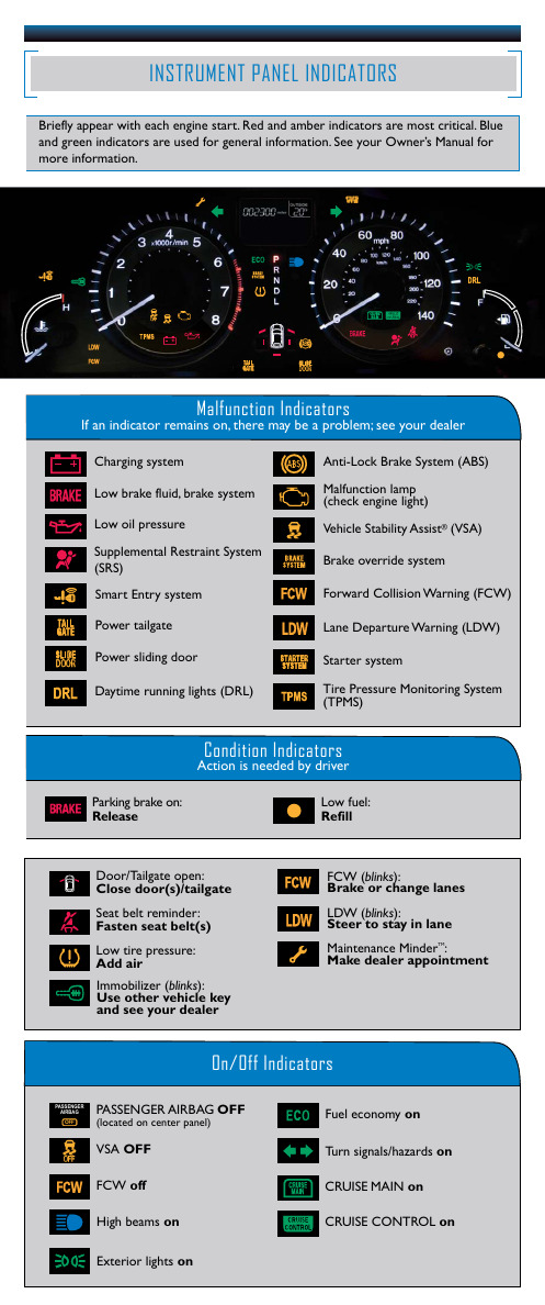
lights (DRL)
PPooT(TwiwrPeMeePrrSr)ettsaasiiullggreaattMeeonitoring System
LLaannee DDVSeeAppOaarrFttFuurree WWaarrnniinngg ((LLDDWW))
Tur
On/Off Indicators Condition IndicaPPtooorwwseerr sslliiddiinngg ddoooorr
NEW STYLE 5/1/2013 7:27 AM PagIIeNN4SSTTRRUUMMEENNTT PPAANNEELL IINNDDIICCAATTOORRSS
Briefly appear with each engine start. Red and amber indicators are most critical. Blue
High beams on
T(T(FTTiuirrPPeeeMMl PPeSSErrc))xeeotssenssriouuormrreeliygMMhotosononnniittoorriinngg SSyysstteemm
CRU CRU
OFF (lRoecafitlel d on center panel)
AAFnnCttW ii--LLLAooo(dcwcbdkklitnaiBrBkierrrspa)a:rkkeeessuSSryyess:tteemm ((AABBSS))
Ma Ma
traint
System
Briefly
LLCooVlwewohsicbbelerraadSkktoaeeboiflfilrltuuy(iiAsdd)s,,s/bbtisarrt®aailk(kgVeeSaAssty)yesstteemm Seat belt reminder: appLLFeooBaawrwrsatkwoeoeiiinotllhvppesrrerereeaiadsscetsshuusbyrerseentelgmti(nse) start. Red
海尔炫色自动洗衣机说明书
1Hood2Tank3Wash and rinse arms 4Wash5Water softener6Pump7Control box8Rinse aid injector9Drain pump10Detergent dispenser 11Wash and rinse armsCode Description150819CABLE HOLDER PG16 WITH HOLE 160772PLUG FOR DOOR (BR-BC-FC)160804GASKET D.6160838SLIDING WASHER TIE ROD FC 160840WASHER160905SLIDING PLATE F. TIE ROD180506DOOR CATCH BR-BC-FC190619DOOR CATCH B-F-R200923DOOR GASKET260223M5X12 MSH/HD SCREW SPECIAL S/S 260238M4 X 10 MUSH/HD SCREW260247SCREW TCB 5X16260250SCREW TB 5X20260414SELF-LOCKING NUT M5260503STAINL.STEEL FLAT WASHER D5 UN 260512ST/ST GROWER WASHER D6260542WASHER D.5320395TOP PANEL FC321807DOOR HINGE FC MACHINES322417RIGHT GUIDE FC322418LEFT GUIDE FC322941DOOR FC54-543-544-HR330233FC DOOR TIE ROD331764FIXING PLATE FOR B-F DOOR GASK 341218HINGE PIN B-F-G341482HOOD FC54-543-544-HR342010PIN FOR TIE ROD DOOR FC351351LEFT PANEL FC54-544-543-HR 351352RIGHT PANEL FC54-543-544-HR 351353FRONT PANEL FC351526LOWER FRONT PANEL390150LOWER BACK PANEL FC390159BACK PANEL FC54A440201RUBBER FOOT D.60X10450821SPRING CLIP FASTENER SNU 3634 461258PLATE FC54E/A463018FC54 NAMECode Description110263TANK HEATER 2000W 230V160121HOSE EPDM D. 5 X 9160203ELBOW 1"1/2 N-S-F-C /DRAIN 160301DRAIN OUTLET 1"1/2 C-S-N160308PUMP INLET HOSE FC160727PLUG 1/2 NTP CAP160755PLUG FOR MACHINES WITHOUT SOFT 161305AIR CHAMBER F45-F80161306HOSE FOR AIR CHAMBER F45-80 170711OVERFLOW PIPE FC180102DRAIN PIPE NUT 1"1/2 F45-55 180109LOCK NUT 1 1/2"180818STRAINER FOR FC200410DRAIN OUTL.WASH.1 1/2"65X47X2 200412GASKET DRAIN 11/2" 45X33X3 200415AIR TRAP GASKET -F2 18,5X10X3 200467DUTRAL GASKET F. AIR TRAP200469STAND PIPE O RING 45X35,5X7 200489GASKET 81X68X3200721DRAIN HOSE 28X35 3MT.200810O-RING 2,62X9,92X15,6 F.GLASSW 200919GASKET FOR SUCTION BASIN FC 260408S/S NUTS D.12260506STAINL.STEEL FLAT WASHER D10 270101HEXAGON LOCK NUT 1/2"290105BRASS-TE-PLUG 1/2"320166VORTEX BREAKER FOR FC MACHINES 450107CLAMP FE ZN 38-50 H=12,2450115ELASTIC CLAMP D.8,3/7,8450519TANK THERMOSTAT SHIELD C-F 460502GASKET 30X21X2Code Description140108PLATE FOR WASH ARM160734END PLUGS RINSE ARM160736WASH ARM PLUG F45160804GASKET D.6170946RINSE JET/RINSE ARM B-F170947WASH JET/WASH ARM F45-80 190203LOWER TEE WASH-RINSE F2-45-55-190218UPPER ARM SUPPORT190624BUSH FOR PLASTIC ARM F45190645LOWER BUSH FOR WASH ARM F 191077LOWER WASH ARM SUPPORT FC54E 200415AIR TRAP GASKET -F2 18,5X10X3 200806O-RING 2,62X13,10X18,34200812O-RING 1,78X17,17X20,73200820O-RING151 46,99X5,33X57,6 200824O-RING 1,78X12,42X15,98200829O-RING 81,92X92,58X5,33200843O RING 2X13X17200844O RING 2X9,5X13,5200845O RING 109 2,62X9,13X14,37 260106SCREW TE 6X25260404STAINLESS STEEL NUTS D6 UNI 55 260504ST/ST FLAT WASHER D6260512ST/ST GROWER WASHER D6260711SCREW 4,2X13 A2 DIN7972261005SCREW F. TEE UP.WASH F2-B41 261009RETAIN.SCREW FOR WASH-RINSE AR 320161UPPER WASH ARM PROTECTION 420552ARM FC-ECONOMYCode Description190203LOWER TEE WASH-RINSE F2-45-55-190218UPPER ARM SUPPORT200787INLET HOSE FC53-FC544-FCHR 200789OUTLET HOSE FC200792HOSE FOR UPPER/LOWER WASH FC54 260103SCREW TE 6X12260126SCREW TE 5X12260404STAINLESS STEEL NUTS D6 UNI 55 260511GROWER WASHER D.5260512ST/ST GROWER WASHER D6260538WASHER 18X6X1,5 ST/ST331922BRACKET F. PUMP "F"450105CLAMP FE ZN. 26-38 H=12,2450107CLAMP FE ZN 38-50 H=12,2450135CLAMP FE ZN. 44-56 H=12,2Code Description110363HEATING ELEMENT 3000W 230V 120144SOLENOID VALVE FCA 20 LT TYPE 120522TANK THERMOSTAT 90?120523SAFETY THERMOSTAT 110?120525BOOSTER THERMOSTAT 2 TEMPERAT. 160105INJECT.INLET HOSE D.6X4160117HOSE 6,3X1,1 WITHE160805GASKET D.8161123HEAT.ELEMENT COVER H42 SNL 180130CONNECTION NUT FOR BY PASS (1/ 180408TEE-NIPPLE F.INJECT.W/CENTR.RE 180411TEE-NIPPLE FOR BY PASS "BTM" 180415TEE NIPPLE DOUBLE "T"190330TEE FOR VAACUM BREAKER191040FRAME F.THERMOSTAT KNOB200113RUBBER HOSE 12 X 22200117RUBBER HOSE 7X16200122HOSE 11X19200416GASKET D. 3/4"200454GASKET F. SALT CONT.200714GLASSWASHER INLET HOSE200800HOSE FOR SALT CONTAINER200815O-RING F. HEAT. ELEM.200822PLUG GASKET OF SALT CONTAINER 201002HOSE260112STAINLESS STEEL TE-SCREW 8X16 280121ELL FOR VAACUM BREAKER330342BOILER C1000/1300-FC-LC330725STANDARD BRACKET F.SOLEN.VALV 331726BRACKET FOR 3 THERMOSTATS 331839BRACKET FOR WATER SOFTENER 450102CLAMP FE ZN 11-17 H=9450103CLAMP FE ZN. 13-20 H=9450114CLAMP FE ZN.22-32 H=12,2450115ELASTIC CLAMP D.8,3/7,8450315KNOB F. THERMOSTAT 90?460502GASKET 30X21X2620120RINSE AID INJECTOR620243VACUUM BREAKER (WITHOUT KIT) 630969COIL S4216 220/50HZ631302SALT CONTAINER640209WATER SOFTENER (4 COLUMNS)Code Description100399PUMP HP0,6 220-50HZ (100740) 100740PUMP 0,6HP 220/240V 4247 100744PUMP HP 0,6 200-220-60HZ 630116-NO MORE AVAILABLE630129VOLUTE PUMP 0,5HP 2247 630222COVER PUMP IB HP 0,4630240PUMP FLANGE 0,6HP-4247 FIR 630413-NO MORE AVAILABLE630419PUMP GASKET 2247 0,5HP 630501SEAL FOR PUMP HP 2-3-3,2 631206CONDENSER 10MF. 450V 85C 631652-NO MORE AVAILABLE631683PUMP IMPELLER 50HZ FIR 4247 631684IMPELLER FOR PUMP 60 HZCode Description110478FLAT CABLE FOR FC54E PCB120356DOOR MAGN.SWITCH120444CONTACTOR 9A 220V 50HZ120460RELAY 16A 220V121277CONTROL PANEL121279ELECTRONIC TIMER130264FUSE 5X20 1A130311TERMINAL BLOCK130605PRESSURE SWITCH 50-30 1 LEVEL 150622FUSE HOLDER SIEMENS 1,5MM-6,3A 150833CABLE HOLDER BC/BR160121HOSE EPDM D. 5 X 9260201SCREW TCP 3X10260205SCREW TCP 4X16260248SPECIAL SCREW TB 5X12260402STAINLESS STEEL NUT D4 UNI 55 260404STAINLESS STEEL NUTS D6 UNI 55 260502S/S FLAT WASHER D.4260510GROWER WASHER D.4260534WASHER260538WASHER 18X6X1,5 ST/ST260542WASHER D.5331892BRACKET332125351816SUPPORT390206450115ELASTIC CLAMP D.8,3/7,8450137COLLAR CONNECTION WITH BASE 31 450221SPRING FOR ELECTRONIC TIMER 461254PLATE FC54E461258PLATE FC54E/A631209ANTI-NOISE FILTERCode Description160714PLUG FOR RINSE AID INJECTOR MO 170701LOCK NUT 1/2" F.INJECTOR180306NIPPLE F.RINSE AID INJECTOR 190107COVER FOR RINSE AID DISPENSER 190108VOLUTE FOR RINSE AID DISPENSER 190803GASKET SUPPORT RING F.INJECT 191018FILTER SUPPORT RINSE AID INJEC 200444SUCTION VALVE RINSE INJECTOR 200816O-RING 2,5X59,2X64,2 RINSE INJ 200825O-RING 3X5X11 RINSE INJECTOR 200861O-RING 14X18X2260142SCREW TE 4X16260213SCREW TCP 5X25260402STAINLESS STEEL NUT D4 UNI 55 260404STAINLESS STEEL NUTS D6 UNI 55 260512ST/ST GROWER WASHER D6 330543FILTER RINSE AID INJECTOR D.17 340483PISTON FOR RINSE AID DISPENSER 381105DIAPHRAGME DISC440405GASKET FOR RINSE AID INJ. 450214SPRING RINSE AID INJECTOR 620120RINSE AID INJECTOR630614DIAPHRAGM RINSE INJECTORCode Description100342DRAIN PUMP 100 W 220V160307DRAIN OUTLET FC170712OVERFLOW PIPE FOR DRAIN PUMP 200346DRAIN HOSE GLASSWASHER 200469STAND PIPE O RING 45X35,5X7 200793DRAIN PUMP INLET HOSE FC 332333BRACKET FOR DRAIN PUMP 450106CLAMP FE ZN 32-44 H=12,2 450114CLAMP FE ZN.22-32 H=12,2 450135CLAMP FE ZN. 44-56 H=12,2Code Description180719DETERGENT DISPENSER SUCTION HO 200467DUTRAL GASKET F. AIR TRAP200607DETERGENT DISPENSER HOSE 251213INJECTOR S/S FOR DETERGENT IN 260408S/S NUTS D.12620242DETERGENT INJECTOR (KIT)Code Description160804GASKET D.6170963RINSE JET X FC190203LOWER TEE WASH-RINSE F2-45-55-190215UPPER WASH/RINSE ARM SUPPORT F 190617BUSH190663BUSH191068LOWER WASH ARM SUPPORT FC-MACH 191069WASH ARM CENTER (FC - MACHINES 191070LOCK NUT FOR WASH ARM CENTER ( 200415AIR TRAP GASKET -F2 18,5X10X3 200806O-RING 2,62X13,10X18,34200820O-RING151 46,99X5,33X57,6200824O-RING 1,78X12,42X15,98200829O-RING 81,92X92,58X5,33200850O-RING260106SCREW TE 6X25260404STAINLESS STEEL NUTS D6 UNI 55 260504ST/ST FLAT WASHER D6260512ST/ST GROWER WASHER D6261005SCREW F. TEE UP.WASH F2-B41 280413RETAIN.LOCK NUT FOR FC RINSE A 320161UPPER WASH ARM PROTECTION 342706SHAFT420548FC WASH ARM (ST/ST)430332RINSE ARM FC 01/00450236SPRING FOR WASHER 170963。
海尔洗衣机用户手册说明书

12 1-25503A
SCREW TSEI
13 1-11533
HEX NUT
14 EAC0100G63A
PLASTIC COVER ASSY M2
15 1-22323A
SELF-TAPPING SCREW
16 1-9841
WASHER,PLAIN d6 ZINC.
17 1-9641
WASHER
Désignation
1
X
M12X35 8.8 A2J
1
X
SONAR VERSION
1
X
COBERT. INF. GRUPO MIS. TORNILLO AUTORR. Transformador 100/230V Transformador Transformador 230/230V Transformador 100/230V TAPÓN CASQUETE NEGRO TORNILLOS M5
1 EAA0263G07A
J-TYPE BRAKE PEDAL
1 EAA0372G98A
ALU BRAKE PEDAL 2 SWICTHES
2 EAC0060G00A
VIBRATORY SYSTEM HOLES CUP
3 EAC0060G02A
FLANGES PROTECTION
4 EAM0006G01A
LCBS-2-6-01 3
Entretoise
Distanciador
,M4X10 M/F 1
VIS CB RONDELLE
Tornillo ARANDELA
M4 x 6 1
UNI 7687
Ø 4,2 1
X
X
X
X
海尔电子产品用户指南.pdf_1702006959.8566868说明书
Clean wastewater pump
1. Disconnect the appliance from the power supply. 2. Remove the filter system. 3. Scoop out any water. 4. Prise off the pump cover using a
9001643299 (020403) SMU4HCW48S
*9001643299*
How to use your appliance
1. Load the tableware.
tate freely.
Only clean tableware that is suitable for dish-
2. Add detergent.
4. Place the lid back on the dispenser and turn to close.
2. Add rinse aid up to the max mark.
max
Programmes
The programme data has been measured in the laboratory according to European standard EN 60436. The consumption figures depend on the programme and additional function selected. The runtime will change if the rinse aid system is switched off or rinse aid needs to be added.
海尔洗衣机说明书.pdf_1702098632.7044532
TiresIt is best to replace all four tires at the same time. If that is not possible or necessary, then replace the two front tires or the two rear tires as a pair. Replacing just one tire can seriously affect your car's handling.The ABS works by comparing the speed of the wheels. When replacing tires, use the same size originally supplied with the car. Tire size and construction can affect wheel speed and may cause the system to work in-consistently.If you ever need to replace a wheel,make sure the wheel's specifications match those of the original wheel that came on your car. Replacement wheels are available at your Honda dealer.Wheels and Tires Wheel:(DX)14 x 5 1/2 JJ (LX, EX)15x 6J J (LX-V6, EX-V6)15 x 6 1/2 JJ Tire:(DX)P195/70R14 90S (LX, EX)P195/65R15 89H (LX-V6, EX-V6)P205/65R15 92VSee Tire Information on page 301 for additional information about tire and wheel size designations. See page 302 for information about DOT Tire Quality Grading.MaintenanceTiresWinter DrivingTires that are marked "M + S" or "All Season" on the sidewall have an all-weather tread design. They should be suitable for most winter driving conditions. Tires without these markings are designed for optimum traction in dry conditions.They may not provide adequate performance in winter driving.For the best performance in snowy or icy conditions, you should install snow tires or tire chains. They may be required by local laws under certain conditions.Snow TiresIf you mount snow tires on your Honda, make sure they are radial tires of the same size and load range as the original tires. Mount snow tires on all four wheels to balance your car's handling in all weather conditions. Keep in mind the traction provided by snow tires on dry roads may not be as high as your car'soriginal equipment tires. You should drive cautiously even when the roads are clear. Check with the tire dealer for maximum speed recommenda-tions.Tire ChainsMount snow chains on your vehicle when warranted by driving condi-tions or required by local laws. Make sure the chains are the correct size for your tires. Install them only on the front tires.4-cylinder modelsIf metal chains are used, they must be SAE class "S". Cable-type traction devices can also be used.6-cylinder modelsUse only SAE class "S" cable-type traction devices.When installing chains, follow the manufacturer's instructions and mount them as tightly as you can.Drive slowly with chains installed. If you hear the chains contacting the body or chassis, stop and investigate.Make sure the chains are installed tightly, and that they are not contacting the brake lines orsuspension. Remove the chains as soon as you begin driving on cleared roads.Chains of the wrong size or that are improperly installed can damage your car's brake lines, suspension, body, and wheels. Stop driving if you hear the chains hitting any part of the car.MaintenanceNOTICE。
海尔电子开发有限公司产品用户手册说明书
1) 0:15 - 0:15 2) 0.050 - 0.050 3) 4.0 - 4.0
1 Suitable programme for running at night: it takes longer, but is extremely quiet.
1
3. Close the lid of the dispenser for rinse aid. a The lid clicks into position.
Hardness mmol/l range
Setting value
Medium Medium Medium Hard Hard Hard
Soft
0 - 1.1
H00
Soft
1.2 - 1.4 H01
1.5 - 1.8 1.9 - 2.1 2.2 - 2.9 3.0 - 3.7 3.8 - 5.4 5.5 - 8.9
9001833317 (030214) SMV4ECX21E
*9001833317*
How to use your appliance
1. Load the tableware.
tate freely.
Only clean tableware that is suitable for dish-
2. Add detergent.
2. Pull up the lower spray arm to remove.
3. Check the outlet nozzles on the spray arms for blockages under running water and remove any foreign bodies.
Adding special salt
海尔电子(Haier Electronics)电子清洁器用户手册:海尔电子无声电洗机(模型:Dish
7. Insert the filter system into the appliance and turn the coarse filter clockwise. Make sure that the arrow markings match up.
and rห้องสมุดไป่ตู้move. 2. On initial start-up: Fill the dispenser right up with
water.
Adding rinse aid
1. Press the catch on the lid
of the dispenser for rinse
2
aid and lift .
washers. Remove large remnants of food from 3. Switch on the appliance .
the tableware. Check that the spray arms can ro-
4. Select the programme. 5. Start the programme . 6. Remove the tableware at the end of the pro-
Tip: Connect your appliance to a mobile device. You can conveniently change all settings using the Home Connect app. 1. Install the Home Connect app on your mo-
3. Press
repeatedly until the right
- 1、下载文档前请自行甄别文档内容的完整性,平台不提供额外的编辑、内容补充、找答案等附加服务。
- 2、"仅部分预览"的文档,不可在线预览部分如存在完整性等问题,可反馈申请退款(可完整预览的文档不适用该条件!)。
- 3、如文档侵犯您的权益,请联系客服反馈,我们会尽快为您处理(人工客服工作时间:9:00-18:30)。
海尔洗衣机xqg70 u1003说明书
连接进水管
1、选择适合的水龙头(前段长度必须大于10mm若水龙头出口端面不平整,请用铿刀铿平,以免漏水)
2、取下进水管接头①234
①按住锁紧杆下端:
②握住进水管,向下压滑动器,取下进水管接头;
③接下标记牌。
3、安装进水管接头
①柠动螺母,露出3至4圈螺纹:
②将进水管接头的四颗螺钉柠松至可将进水管接头套在水龙头上;
③如果进水管水龙头无法套在水龙头上,请取下衬套在安装;
④将其中一个螺钉事先旋到大致适合位置,在将进水管套在水龙头上,将其余三颗螺钉均匀,柠紧,确认到位后,旋紧螺母。
4、连接进水管
①压下滑动器,将水管插入进水管接头;
②用锁紧杆挂住水管接头,然后松开滑动器,直到听到“啪”的一声。
5、连接洗衣机
①将进水管另一端的螺母套到进水阀接头上;
②柠紧进水管螺母并确认螺母紧固到位。
6、检查进水管是否连接好
①检查连接是否牢固;
②安装完毕后,打开水龙头,检查是否漏水;
③每次使用洗衣机前,请检查确认进水管与水龙头连接牢靠
④切勿强力弯曲进水管。
粘贴毛毡,安装降噪板
1、将毛毡粘贴在降噪板的一侧。
2、将洗衣机向后倾斜,卸下四个底脚。
3、降噪板附有毛毡的一面朝内,将将底脚螺栓穿过四个孔装在壳体上旋紧,重新放平机器。
注意事项:
洗衣机安装到位后,插头应在可触及范围内,不要通过搜拉电源线拔下洗衣机插头。
若需更换电源线,需由专业人员更换或与本公司售后部门联系。
洗衣机底脚不能压电源线,电源线不能有折断,压细等问题。