柏林之声011前级放大器中文说明书
Busch-AudioWorld 1 MDRC 放大器 8208-500 操作指南说明书

Operating Instructions Busch-AudioWorld®MDRC amplifier 8208-500 Busch-AudioWorld®1Safety (3)2Intended use (3)2.1Environment (3)3Technical data (4)4Setup and function (4)4.1Features of function and equipment (4)4.2Possible combinations (5)5Installation and electrical connection (6)5.1Requirements for the electrician (6)5.2General mounting instructions (7)5.3Mounting (7)5.4Electrical connection (8)5.4.1Connecting terminals and LED displays (8)5.4.2Installation / connection possibilities (9)1 SafetyWarningElectric voltage!Risk of death and fire due to electrical voltage of 230 V.– Work on the 230V supply system may only be performed by authorised electricians!– Disconnect the mains power supply prior to installation and/or disassembly!2 Intended useThe device is part of the Busch-AudioWorld® system and is to be used exclusively with the components that are supplied and licensed as described in the "Structure and Function" chapter. The device must only be installed in dry indoor rooms.Consider the protection of the environment!Used electric and electronic devices must not be disposed of with domestic waste.– The device contains valuable raw materials which can be recycled. Therefore, dispose of the device at the appropriate collecting depot.All packaging materials and devices bear the markings and test seals for proper disposal. Always dispose of the packaging material and electric devices and their components via the authorized collecting depots and disposal companies.The products meet the legal requirements, in particular the laws governing electronic and electrical devices and the REACH ordinance.(EU Directive 2002/96/EC WEEE and 2002/95/EC RoHS)(EU REACH ordinance and law for the implementation of the ordinance (EC) No.1907/2006)Operating InstructionsBusch-AudioWorld®Technical data 3 Technical dataDesignation ValueRated voltage 230 V AC, ±10%, 50 / 60 HzSupply current 1.5 A, 15 V, SELVOutput power 2 x 10 W or 1 x 20 W bridgedLoudspeaker impedance 2 – 16 ohm stereo4 – 16 ohm monoNumber of loudspeakers No. 8222 EB 8224 EB in parallel operation• Mono 4 units• Stereo 2 x 8 unitsMounting method DIN rail: (VDE 50022)Cable cross-section top 2 wires each with max. 6 mm2Cable cross-section bottom 2 wires each with max. 4.5 mm2Protection type IP 20Temperature range 5 °C … 40 °CDimensions 7 TE à 18 mmLine type audio bus J-Y(ST)Y n x 2 x 0.84 Setup and function4.1 Features of function and equipmentThe MDRC amplifier is used when the power output of the Busch-Audioworld® is not adequate and needs to be raised, e.g. for larger rooms.It is also used when an independent public address system is planned.Operating InstructionsBusch-AudioWorld ®Setup and function4.2 Possible combinations8208-5008208-5001751-2xX8214 UX1751-7xX8218 UX1751-8xX8221 UX2147 U-xX822X EBX8210 UX8223 UX8211 UX5 Installation and electrical connectionWarningElectric voltage!Risk of death due to electrical voltage of 230 V during short-circuit in the low-voltage line.– Low-voltage and 230 V lines must not be installed together in a flush-mounted socket!5.1 Requirements for the electricianWarningElectric voltage!Install the device only if you have the necessary electrical engineering knowledge and experience.• Incorrect installation endangers your life and that of the user of the electrical system.• Incorrect installation can cause serious damage to property, e.g. due to fire.The minimum necessary expert knowledge and requirements for the installation are as follows:• Apply the "five safety rules" (DIN VDE 0105, EN 50110):1. Disconnect from power;2. Secure against being re-connected;3. Ensure there is no voltage;4. Connect to earth and short-circuit;5. Cover or barricade adjacent live parts.• Use suitable personal protective clothing.• Use only suitable tools and measuring devices.• Check the supply network type (TN system, IT system, TT system) to secure the following power supply conditions (classic connection to ground, protective earthing, necessaryadditional measures, etc.).5.2 General mounting instructions• Terminate all branches of the wiring system via a connected bus device (e.g., indoor station, outdoor station, system device).• Do not install the system controller directly next to the bell transformer and other power supplies (to avoid interference).• Do not install the lines of the system bus together with 230 V- lines.• Do not use common cables for the connecting wires of the door openers and wires of the system bus.• Avoid bridges between different cable types.• Use only two wires for the system bus in a four-core or multi-core cable.• When looping, never install the incoming and outgoing bus inside the same cable.• Never install the internal and external bus inside the same cable.5.3 MountingThe MDRC must only be installed on mounting rails according to DIN EN 500022. The MDRC is latched onto the mounting rail.5.4 Electrical connection5.4.1 Connecting terminals and LED displays1 System bus |2 LED displays |3 Power supply |4 Loudspeaker | 5System busDesignation AssignmentN ext. Neutral conductor when operating without 8201 / 8202R 1 Signal input from audio bus (right channel 1)NC Supporting terminal (nc)L +/- Signal input (controlled)LED displaysNo. AssignmentON Lights during operationSTANDBY Mute can be activated only by a music signal.Power supplyNo. AssignmentN 230 V AC, ±10%, 50 / 60 HzLLoudspeakerNo. Assignment10 W + 10 W20 WLS: +L / +R Loudspeaker: right / leftDesignation Assignment1 – 10 V5.4.2 Installation / connection possibilitiesFig. 1: Circuit diagramFig. 2:DevicesA 8201 / 8202B 0213C 8211 UD 8208-500Fig. 3: Installations / connection possibilitiesDevicesA 8210 UB 8208-500C Potentiometer 2112 / 6550Fig. 4: Mono modeOperating InstructionsBusch-AudioWorld ®1473-1-8311 | R e v . 01 | 17.12.2012A member of the ABB GroupBusch-Jaeger Elektro GmbH PO box58505 LüdenscheidFreisenbergstraße 2 58513 Lüdenscheid Germany ***************.comCentral sales service:Phone: +49 (0) 2351 956-1600 Fax: +49 (0) 2351 956-1700NoticeWe reserve the right to at all times make technical changes as well as changes to the contents of this document without prior notice. The detailed specifications agreed to at the time of ordering apply to all orders. ABB accepts no responsibility for possible errors or incompleteness in this document.We reserve all rights to this document and the topics and illustrations contained therein. The document and its contents, or extracts thereof, must not be reproduced, transmitted or reused by third parties without prior written consent by ABB.Copyright© 2012 Busch-Jaeger Elektro GmbH All rights reserved。
放大器操作说明

放大器操作说明一、放大器的设置1.打开Nexus 元件的电源并使Nexus 元件初始化。
2.如果Nexus 元件没有显示主菜单,则应按底下的“Home ”键,直到出现主菜单。
在主菜单上应有诸如“Amplifier Set -up (放大器设置)”,“Transducer Set -up (传感器设置)”等选项。
如照片1所示:3.滚动到“Amplifier Set -up (放大器设置)”并按底下的“↙”一次。
如照片2所示:照片 1照片 24.在“Amplifier Set -up (放大器设置)”菜单下,应通过在底下箭头键来滚动到“Hz ”,以确保“Hz ”显示加亮。
一旦“Hz ”显示加亮,则按 “Ch ↓”键。
随后应用“+”和“-”按键来设置Hz (频率)为A 。
一旦通道1设置为A ,则应按 “Ch ↓”键,并对通道2,3和4作同样的工作。
如果是2通道Nexus 元件,那么只需要编程两个通道。
当所有通道设置为A 时,按“Home ”键返回。
如照片3所示:然后,用“→”键移动到“Out (输出)”。
一旦“Out (输出)”被显示加亮,使用“Ch ↓”键和“+”与“-”键把每个通道都设置为316mV/Pa 。
当所有通道都设置为316mV/Pa 后,按“Home ”键返回。
最后回顾一下菜单,确保所有的通道都被分别设置在A 下,“Out ”输出为316 mV/Pa 。
当所有设置项都设置正确后,按“Home ”键返回。
如照片4所示:照片 3滚动到“Transducer Set -up (传感器设置)”下并按底下的“↙”一次。
如照片5所示:(此步可以省略,因为麦克风的灵敏度是自动识别的不用设置)编辑此菜单需要声学传感器的校准数值。
当得到校准数值后,滚动到“Sensitivity (灵敏度)”并按“Ch ↓”键。
如照片6所示:照片 4照片 5随后将处在显示加亮的十进制数值的通道#1。
用“+”与“-”键把此数值设置为对应于此通道/声学传感器的校准/灵敏度数值。
效果器中文说明书大全
效果器中文说明书大全在这里我将为大家搜集各种常用的效果器中文说明书以后会不断的补充新的说明书POD 2.0中文说明,音色列表,以及相关所有资料Line 6 POD 2.0 控制与连接中文简易说明 1 开关- 在POD 2.0右侧。
按下它可以开启你的POD2.0。
2 输入- 在POD 2.0右下侧。
把你的吉他连接在这里。
3 耳机接口- 在POD 2.0的左下侧。
连接你的耳机以做静音练习。
音量由OUTPUT控制。
其耳机放大器可供所有型号的耳机使用。
4 输出- 在POD 2.0面板的最左边(OUTPUT)。
控制主输出音量。
当储存音色时,这一值是不被记录的。
改变主音量并不改变音色。
《注:在主输出音量开到最大时,POD 2.0会给您最佳的信噪比。
相反,当主音量开得较小时,会出现嘶噪。
所以当您录音时,尽量将您的OUTPUT开到最大。
请确定您所连接的设备的输入口属于“线输入”(LINE LEVEL), 而不是麦克风/吉他输入。
线输入可以允许POD 2.0的总输出开到最大(或接近最大)从而得到最佳的音色。
如果您的设备的输入类型为麦克风或吉他,请把输入放到较低,把POD 2.0的输出放到较大。
》 5 左右输出- 在POD 2.0的左上侧。
在左右输出的中间有DIRECT/AMP字样,输出时将你的调音台/录音设备连接到左输出(DIRECT),吉他音箱/监听音箱连接到右输出(AMP) 6 A.I.R Mode拨档- 在POD 2.0的左右输出中间,A. I. R.定向录音输出属Line6独有,专门为直路录音设计,将A.I.R Mode拨档调到左输出(DIRECT)一边即可。
7 踏板接口- 在POD 2.0上方,可与LINE6 Floor Board/FB连接。
POD 2.0不支持LINE6 FBV4. 8 MIDI输入与输出- 在POD 2.0右上方。
通过MIDI线与MIDI设备间接9 Drive- 其控制您所选择的放大器(Amp)的Drive。
博斯音频放大器说明书
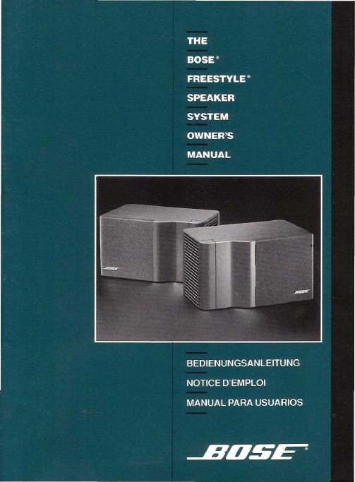
Place the left speaker on the left side of the room and the right speaker on the right side of the room. Make sure that the ports - the narrower, louvered end ofthe speaker- face toward each other or face upward(Figure 1).
Freestyle speakers incorporate some of the most advanced technologies developed at Bose Corporation. At the heart of this system is the Helical Voice Coil driver, the same type of driver used in our 901 ® DirectlReflecting® speaker system, known for its accuracy, power handling, and reliability. This new version of the HVC driver is designed especially forthe Freestyle system, to provide exceptional power handling and extended high frequency performance. Apatented, curved and flared porting system also enables these small speakers to produce low frequencies, once available only from amuch larger enclosure.
Behringer MICROPHONO PP400 V 5.0 唱机前置放大器说明书
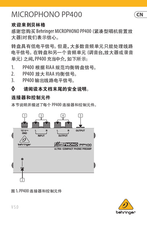
MICROPHONO PP400V 5.0欢迎来到贝林格感谢您购买 Behringer MICROPHONO PP400 (紧凑型唱机前置放大器)对我们表示信心。
转盘具有低电平信号。
但是, 大多数音频单元只能处理线路电平信号。
在转盘和另一个音频单元 (调音台,放大器或录音单元) 之间, PP400 充当中介, 如下所示:1. PP400 根据 RIAA 规范均衡转盘信号。
2. PP400 放大 RIAA 均衡信号。
3. PP400 输出线路电平信号。
◊ 请阅读本文档末尾的安全说明。
连接器和控制元件本节说明并描述了每个 PP400 连接器和控制元件。
图 1: PP400 连接器和控制元件2MICROPHONO PP400(1) 12 伏连接器: 要将电源设备连接到 PP400, 请使用12 V 连接器。
将电源设备连接到电源会自动打开 PP400。
要断开设备与电源的连接, 请拔出电源线插头。
(2) 在 LED: 将设备连接到电源后, ON LED 点亮。
(3) 输入(左和右) 连接器:要将转盘信号发送到 PP400, 您需要 RCA 音频电缆 (立体声)。
使用此电缆连接:• 转盘上的左侧输出到 PP400 上的L(左侧)输入• 转盘上的右侧输出到 PP400 上的R(右侧)输入PP400 可以通过以下连接器之一输出线路电平信号:• RCA ((4)输出 L 和 R )• ¼" TRS ((5)输出)◊ 请勿同时使用两个 PP400 OUTPUT 。
(4) 输出(左和右)连接器: 要使用这些 RCA 连接器, 您需要一条 RCA 音频电缆 (立体声)。
使用此音频电缆连接:• PP400 上的L(左) 输出到放大器, 记录单元或混音器上的左输入。
(在调音台上, 使用 CD 或 TAPE 输入。
)• PP400 上的R(右) 输出到放大器, 录音单元或混音器上的右输入(5) 输出 连接器: 要使用此 ¼" TRS (立体声) 连接器, 您需要音频电缆。
ARRIS 1 GHz MB100 放大器说明书
STARLINE SeriesMB1001 GHzAmplifierFor cable operators looking to ensure maximum backwards compatibility and scalability and protect network investments, ARRIS offers solutions that deliver new services with minimal CAPEX, enhance network efficiency, and increase subscriber satisfaction. The ARRIS 1 GHz MB100 Amplifier enables cable operators to increase forward capacity while maintaining current amplifier spacing of existing 750 and 870 MHz systems. The MB100is available as a complete unit for greenfield deployments or as a drop‐in RF module for 1 GHz upgrades to legacy STARLINE MB75 and MB87 amplifiers.PRODUCT OVERVIEWFEATURES•Simplify plant upgrades with modular RF design and 1.2 GHzcapable housing•Improve amplifier reach with optional GaN technology andincreased station tilt•Maintain current amplifier spacing with high output GaAstechnology•Expand return path bandwidth with plug‐in diplex filter supportto 85 MHz•Minimize RF drift over temperature with optional analog orQAM ADUForward PathThe standard MB100 configuration is equipped with second‐generation Enhanced Gallium Arsenide (E‐GaAs) technology with two driven RF outputs, which provides superior distortion performance over standard silicon and competing GaAs technologies. If operators require longer reach, the MB100 can be configured with optional Gallium Nitride (GaN) hybrid technology, which allows for a 3 dB increase in output level over the standard GaAs option.To provide additional system flexibility, easy installation and maintenance, the MB100 is compatible with standard accessories such as attenuators, equalizers, ADUs or QADUs, automotive fuses, and FTEC crowbar circuits. The amplifier maintains output level via an optional plug‐in drive unit. In addition, operators can control level manually, thermally with the TDU (thermal drive unit) accessory, or electronically with the automatic drive unit (ADU). The ADU can support either analog or QAM pilot channels.The MB100 uses modular diplex filters, which operators can change to increase return bandwidth. The following filters are available for use with all US‐style STARLINE RF distribution amplifiers (models BLE, MB/MBV3, BT):•K‐split (5 to 42 MHz/54 to 1003 MHz)•A‐split (5 to 65 MHz/85 to 1003 MHz)•N‐split (5 to 85 MHz/104 to 1003 MHz)Return PathThe MB100comes standard with a high‐gain return amplifier. Operators can select SRE return path equalizers ranging from 0 to 12 dB.Backward CompatibilityOperators can make the MB100 electronics package backward compatible with the 10‐Amp MB*/* housing by installing theMB‐15AII Kit. These kits contain 50 mil gold plated platform assemblies, which make it possible for the amplifier to carry 15 Amperes continuous through its input or output ports.COMPATIBILITYPlatform MB‐550MB‐750D MB‐750SH MB86MB87 Upgrade to MB100No No Yes*Yes*Yes* Requires MB‐15AII KitRELATED PRODUCTSADU/QADU MBV3BLE100BT100SFE/SRE EQ Installation ServicesFlex Max®RF AmplifiersSpecifications –E‐GaAsSpecifications Units Forward ReturnFrequency split1MHz K (54 –1003)A (85 –1003)N (104 –1003)19K (5 –42) A (5 –65) N (5 –85)Flatness 2,19dB±0.75±0.5 Minimum Full Gain 3dB4620 Operation Gain 4dB42NA Manual Bode Slope Control Range 5dB±4NA Noise Figure 6dB98 Standard Slope Reference Frequency MHz1003/550/5435 (flat) Reference Output Level dBmV51/44/37—Operating Interstage Slope7dB14 ±1NA Standard Slope DistortionChannels, Number of NTSC17Composite Triple Beat (CTB) 8,16Cross Modulation (XM) 9,16Composite Second Order(CSO) 8,10,16 Carrier to Intermodulation Noise (CIN)21 Channels, Number of 256 QAMCarrier to Intermodulation Noise (CIN)20,21dBcdBcdBcdBdB7976.568.57165154656807081———Test Point 11dB20 (±1.0 dB)20 (±1.0 dB) Return Loss 12dB14.515 Hum Modulation @ 12A dBc< 60< 60 Hum Modulation @ 15A 12dBc< 60< 65 DC Voltage VDC24Current DC Max. 13mA1600Power Consumption Max.W52AC Input Voltage Range VAC38–90AC Current Draw Max.@ 90 VAC@ 60 VAC@ 38 VAC A0.580.921.45AC Bypass Current (all ports) 14A15Group Delay 15K‐split55.25 to 58.83 MHz nSec52NA Group Delay 15A‐split86.25 to 90.68 MHz nSec28NA Group Delay 19N‐split109.25 to 112.83 MHz 112.25 to 116.68 MHz nSecnSec149NANAOperating Temperature Range °C°F–40 to +60–40 to +140Housing Dimensions, L x W x D InchesMm15.4 x 9.6 x 5.5292 x 244 x 140Weight lbKg156.8Specifications –E‐GaNSpecifications Units Forward ReturnFrequency split1MHz K (54 –1003)A (85 –1003)N (104 –1003)19K (5 –42) A (5 –65) N (5 –85)Flatness 2,19dB±0.75±0.5 Minimum Full Gain 3dB46NA Operation Gain 4dB4220 Manual Bode Slope Control Range 5dB±4NA Noise Figure 6dB98 Ultra Slope Reference Frequency7MHz1003/550/5435 (flat) Reference Output Level dBmV57/48/39—Operating Interstage Slope dB18 ±1NA Ultra Slope DistortionChannels,Number of NTSC17Composite Triple Beat (CTB) 8,16Cross Modulation(XM) 9,16Composite Second Order(CSO) 8,10,16 Carrier to Intermodulation Noise (CIN)21 Channels, Number of 256 QAMCarrier to Intermodulation Noise (CIN)20,21dBcdBcdBcdBdB7970626958154586807081———Standard Slope Reference Frequency 7MHz1003/550/5435 (flat) Reference Output Level dBmV51/44/37—Operating Interstage Slope 6dB14 ±1NA Standard Slope DistortionChannels, Number of NTSC17Composite Triple Beat (CTB) 8,16Cross Modulation (XM) 9,16Composite Second Order(CSO) 8,10,16 Carrier to Intermodulation Noise (CIN)21 Channels, Number of 256 QAMCarrier to Intermodulation Noise (CIN)20,21dBcdBcdBcdBdB7975667166154666807081———Test Point 11dB20 (±1.0 dB)20 (±1.0 dB) Return Loss 12dB14.5 15 Hum Modulation@ 12A dBc< 60<60 Hum Modulation @ 15A 18dBc< 60< 65 DC Voltage VDC24Current DC Max. 13mA1600Power Consumption Max.W52AC Input Voltage Range VAC38–90Specifications –E‐GaN(continued)Specifications Units Forward ReturnAC Current Draw Max.@ 90 VAC@ 60 VAC@ 38 VAC A0.580.921.45AC Bypass Current (all ports) 14A15Group Delay 15K‐split55.25 to 58.83 MHz nSec52NA Group Delay 15A‐split86.25 to 90.68 MHz nSec28NA Group Delay 19N‐split109.25 to 112.83 MHz 112.25 to 116.68 MHz nSecnSec1412NANAOperating temperature range°C°F –40 to +60–40 to +140Housing dimensions, L x W x D inchesmm 15.4 x 9.6 x 5.5 292 x 244 x 140Weight lbkg 15 6.8Notes:1.Operating passband of station. Diplex filters are plugged into the electronic chassis.2.Referenced to the average gain across the passband.3.Minimum full gain at 1003 MHz includes loss of equalizer but Bode slope reserves have not been set. Return gain includes loss of SRE‐*‐4 return equalizer. Measured at Fmaxreturn.4.Includes loss of gain reserves as well as equalizer.5.From midpoint (typical setting is –4 dB at 1003 MHz @ 25 °C). This control should not be used for gain reduction.6.Specified at the housing cable entry facility over temperature and includes the loss of 1 dB for the pre‐stage equalizer. The return noise figure includes the station loss preceding theRF hybrid.7.Amount of slope created and cable equivalence of fixed, plug‐in interstage equalizer.8.Measured with CW carriers and spectrum analyzer over specified temperature range. References the worst‐case channel.*9.Measured with wave analyzer and synchronous, 100% depth modulated channels. References the worst‐case channels over specified temperature range.*10.Refers only to beat clusters that fall 0.75 MHz and 1.25 MHz above the subject picture carrier.11.Test points should be used with GFAL adapter.12.Match measurement at the station input and output, cable‐entry facilities, at the specified passband for operational gain.13.Current draw at 24 VDC.14.Stated in RMS continuous.15.Specified for standard NTSC video, where delay is the delta from picture carrier to 3.58 MHz color subcarrier. Reverse delay is in a 1.5 MHz bandwidth.16.Worst‐case over temperature in a cascade.17.NTSC 79 Channel forward, 75 QAM carriers –6dB relative to analog CW carriers. 6 Channel return.18.Specification is 55 from 5 to 10MHz at 15A.19.For N‐split (5–85/104–1003MHz) roll‐off from 105 MHz to 102 MHz < 1.0 dB. Group delay from 103.25 MHz to 105.25 MHz is < 22 ns.20.154 QAM carriers 54‐1002 MHz. Carriers are ‐6dB relative to virtual analog levels.21.Room temperature performance.* Specifications are compliant with the test methods as stated in NCTA Recommended Practices for Measurements on Cable TelevisionNote: Specifications are subject to change without notice.Copyright Statement: ©ARRIS Enterprises, Inc. 2015 All rights reserved. No part of this publication may be reproduced in any form or by any means or used to make any derivative work (such as translation, transformation, or adaptation) without written permission from ARRIS Enterprises, Inc. (“ARRIS”). ARRIS reserves the right to revise this publication and to make changes in content from time to time without obligation on the part of ARRIS to provide notification of such revision or change. ARRIS and the ARRIS logo are all registered trademarks of ARRIS Enterprises, Inc. Other trademarks and trade names may be used in this document to refer to either the entities claiming the marks and the names of their products. ARRIS disclaims proprietary interest in the marks and names of others. The capabilities, system requirements and/or compatibility with third ‐party products described herein are subject to change without notice.MB100_DS_27OCT141 GHz MB Ordering GuideRequired AccessoriesPart NumberModelDescription535723‐001‐00531124‐001 to ‐022531161‐001 to ‐010SFE ‐100‐0SFE ‐100‐1 to ‐22SCS ‐1 to SCS ‐10Forward 1003 MHz equalizer (0 dB) ‐or ‐Forward 1003 MHz equalizer (values 1 to 22 dB 1n 1 dB steps)‐or ‐Cable simulator (values 1 to 10 dB in 1 dB steps)531163‐XXX ‐00SRE ‐*‐*Return equalizer, 5‐42 MHz (K ‐split), 5‐65 (A ‐split), 5‐85 (N ‐split), values 0 to 12 dB 1n 2 dB steps 531186‐XXX ‐00JXP ‐*BPlug ‐in attenuator/pad (values 0 to 26 dB in 1 dB steps)Optional AccessoriesPart NumberModelDescription531230‐001‐00SP100Splitter (1 GHz) to activate third output ‐or ‐531230‐002‐00DC100/8Directional coupler (1GHz)to activate third output (8dB)531230‐003‐00DC100/10Directional coupler (1GHz)to activate third output(10dB)531230‐004‐00DC100/12Directional coupler (1GHz)to activate third output (12dB)594742‐002‐00QADU ‐609.00/S ‐R 609 MHz QAM Automatic Drive Unit 594742‐001‐00QADU ‐711.00/S ‐R 711 MHz QAM Automatic Drive Unit 531236‐003‐00ADU ‐499.25/S ‐R 499.25MHz Automatic Drive Unit 531344‐002‐00MB ‐15AII ‐KIT15 Amp kit to upgrade 10 Amp platforms(rev 10-2014) Customer CareContact Customer Care for product information and sales:•United States: 866‐36‐ARRIS •International: +1‐678‐473‐5656Notes:1.Not all combinations in the ordering guide are available. This is a guide only.2.FTECs are included in all models as standard.。
Rane MS 1S 微型微音频放大器数据表说明书

Data Sheet-1MS 1SMICROPHONE STAGEGeneral DescriptionThe Rane MS 1S Mic Stage preamplifier provides the answer when you need just one microphone input in an otherwise line-level world. Give us a call to go from either a dynamic, condenser or electret microphone to a line-level input with a minimum of noise, distortion, cost and hassle.The MS 1S provides 48 V switchable Phantom Power with indicator LED, continuous rotary Gain trim between 18 dB and 66 dB, Signal/Overload LED, and XLR balanced Input & Output connec-tors. A Polarity switch and high-current cross-coupled output line driver round out the features.The MS 1S utilizes one of the finest ultra low noise amplifier designs available. Featuring a true differential input with high common-mode rejection, use of the MS 1S guarantees performance usually found only in mixing consoles costing thousands of times as much. Of course, for all of that extra money you receive a proportional increase in KPSI (knobs per square inch).The MS 1S replaces the MS 1B Mic Stage with a new internal universal power supply. The width increases by one inch, and all other features are the same.Features• 120 dB dynamic range • Gain Control• Signal / Overload Indicator • Polarity SwitchPRELIMINARY DAT A SHEET / MANUAL • Switchable 48 V Phantom Power • True differential Input • Cross-coupled line driver• Internal 100-240 VAC universal powersupplyMS 1S MICROPHONE STAGEFeatures and SpecificationsParameter Specification Limit Units Conditions/CommentsInput Impedance10k1%ΩBalanced 5k + 5kGain Range18 to 66typ.dBPhantom Power+484%V10 mA max...........Impedance 6.81k1%ΩEach leg..........Load Regulation0.1typ.%0 to 14 mA..........RMS CM Noise.003typ.%% of Vout (10 Hz to 10 kHz)Max. Input Level+10 / -32min.dBu Gain 18 / 60, balanced outputEquivalent Input Noise-128typ.dBu20 kHz BW, Rs=150 Ω, Gain = 60 dB Signal to Noise Ratio96typ.dB20 kHz BW, Rs=150 Ω, Gain = 18 dB, re 4 dBu Dynamic Range120 / 95typ.dB Gain 18 / 66CMRR80typ.dB Rs=150 Ω, 120 Hz, Gain = 60 dB Frequency Response..........Gain 60 dB45 to 200k typ.Hz+0, -3dB..........Gain 18 dB30 to 200k typ.Hz+0, -3dbTHD+Noise (gain 60 dB).007 (Output=+20 dBu)typ.%55 Hz to 20 kHz, 20 kHz BW, Rl=10 kΩTHD+Noise (gain 18 dB).001 (Output=+20 dBu)typ.%50 Hz to 20 kHz, 20 kHz BW, Rl=10 kΩLine Driver Active Cross-coupled Gain 5.2 / 6 dB typ. unbalanced / balanced Max. Output Level+22 / +27min.dBu Unbalanced / Balanced, 2 kΩ loadOutput Impedance501%ΩEach LegSignal Indicator 2 / 8typ.dBu Unbalanced / Balanced output, Green LED Overload Indicator14 / 20typ.dBu Unbalanced / Balanced output, Amber LED Output Cable Length1000 feet / 300 meters typ.Belden 8451 or equivalentUnit: Agency Listing UL/cUL/CE PendingMaximum Power3WUniversal Line Voltage100-240VAC50/60 HzPower Cord C5 cord to C6 inlet IEC 60320-1Unit Size 1.64"H x 6.8"W x 4.26"D(4.2 cm x 17.3 cm x 10.8 cm) ..........Weight 1 lb 1 oz(0.5 kg)Shipping Size 3.6"H x 11.75"W x 7.2"D(9.5 cm x 30 cm x 18 cm) ..........Weight 4 lb(1.8 kg)Data Sheet-2Data Sheet-3MS 1SMICROPHONE STAGEBlock DiagramApplication InformationUses and applications for the MS 1S should be obvious. But then again, it’s obvious to us our taxes are too high and nothing is being done about that. With this in mind, perhaps a few words on us-ing the MS 1S might not be wasted.BALANCED USEThe MS 1S provides a true cross-coupled balanced output. This is equivalent to an electronic simulation of a transformer output. Rane follows the AES standard of pin 2 = hot.When running a long cable back to the mixer, run a line-level balanced line rather than a mic-level line. The compact MS 1S can mount closer to the micro-phone, provide a local volume control (or not, just pull the knob off), while the stronger signal minimizes RF and hum irritations.UNBALANCED USEBalanced use is recommended to mini-mize noise. Unbalanced lines are usually quiet under 10 feet (3 meters), but longer runs will introduce the hum and interfer-ence you are trying to avoid. When you must drive an unbalanced device with the MS 1S's balanced output, keep the cable short, and connect pin 2 to the “+” or “hot” lead, and tie pin 3 and ground together at the shield .MIXINGThe MS 1S is designed to fill the need for adding a microphone channel to line-level mixers, such as the Rane SM 26S or SM 82S. Many installations using either of these products invariably wind up with one unused input that would do the job perfectly if only it could operate at mic-level. In rides the MS 1S to the rescue.MIC 12-60 dBDIGITAL RECORDING AND SAMPLING Another handy use for the MS 1S is in recording applications. Many popular products do not have a high enough qual-ity mic preamp to suit the resolution of the digital processing electronics. Such irony. Using the ultra low noise MS 1S to bring the mic inputs up to extremely high quality line-level is an easy and affordable solution for this dilemma. No garbage in; no garbage out. Clippity-clop; clippity-clop.MICROPHONE TYPESThe available gain and large input range of the MS 1S allows the use of virtually any type of microphone. True 48V phantom power guarantees the MS 1S works with every microphone. The better the mic, the better the MS 1S sounds.Ah, the sound of the thundering hoofs is deafening.Data Sheet-4MS 1SMICROPHONE STAGEAll features & specifications subject to change without notice. DOC 104514©Rane Corporation 10802 47th Ave. W., Mukilteo WA 98275-5098 USA TEL 425-355-6000 FAX 425-347-7757 WEB Architectural SpecificationsThe microphone preamplifier shall be a single channel stand-alone unit with a removable IEC power cord. The unit shall accept voltages from 100 to 240 VAC. The input and output shall be fitted with XLR connectors. A polarity inverting switch shall be included. Phantom power of no less than 48 volts shall be provided in compliance with IEC 60268-15 and be controlled by a slide switch with an LED indicator. A gain control shall be provided with 18-66 dB adjustment range. Power, system signal and overload indicators shall be provided. High current cross-coupled active output line driver shall be standard, as well as input RFI filter protection.The unit shall be a Rane MS 1S Micro-phone Stage.Dimensions。
柏林之声011前级放大器中文说明书

1 用户使用手册
前置扩音器011(型号)
柏林之声
耳边的艺术
高端产品,德国制造
柏林之声音响设备有限公司.柏林 kolonnens街 30号.邮编10829 电话+49/30/787968-0 传真+49/30/787968-68 网址
www.burmester.de
2
尊敬的音响发烧友,
感谢您选择此款柏林之声音响配置设备。
我们由衷的感激您对我们(产品)的
信任。
您选择了一款高保真,高制作工艺,高技术创新,以及(在接配操作上)具有
很强灵活性的前置扩音器。
我们强烈建议您完整在首次安装调试011号设备前完整的阅读此操作手册。
它
会让您更好的机器的效果发挥到极致。
如还有问题,请向销售商或我们(制造商)直接联系。
(预祝)您享受(视)听新感觉。
柏林之声团队
6
7
9 (其他)一般操作指令
设备技术标准
耗能关闭(但连接):6瓦
待机:6瓦
打开:25瓦
线增益低:12分贝
高:15分贝(当Vol=60)
大小尺寸(宽x高x深)482x95x345毫米
重量9.6千克
注意尺寸不包括接线所需要的空间。
- 1、下载文档前请自行甄别文档内容的完整性,平台不提供额外的编辑、内容补充、找答案等附加服务。
- 2、"仅部分预览"的文档,不可在线预览部分如存在完整性等问题,可反馈申请退款(可完整预览的文档不适用该条件!)。
- 3、如文档侵犯您的权益,请联系客服反馈,我们会尽快为您处理(人工客服工作时间:9:00-18:30)。
1 用户使用手册
前置扩音器011(型号)
柏林之声
耳边的艺术
高端产品,德国制造
柏林之声音响设备有限公司.柏林 kolonnens街 30号.邮编10829 电话+49/30/787968-0 传真+49/30/787968-68 网址
www.burmester.de
2
尊敬的音响发烧友,
感谢您选择此款柏林之声音响配置设备。
我们由衷的感激您对我们(产品)的
信任。
您选择了一款高保真,高制作工艺,高技术创新,以及(在接配操作上)具有
很强灵活性的前置扩音器。
我们强烈建议您完整在首次安装调试011号设备前完整的阅读此操作手册。
它
会让您更好的机器的效果发挥到极致。
如还有问题,请向销售商或我们(制造商)直接联系。
(预祝)您享受(视)听新感觉。
柏林之声团队
6
7
9 (其他)一般操作指令
设备技术标准
耗能关闭(但连接):6瓦
待机:6瓦
打开:25瓦
线增益低:12分贝
高:15分贝(当Vol=60)
大小尺寸(宽x高x深)482x95x345毫米
重量9.6千克
注意尺寸不包括接线所需要的空间。