TME安装调试指南
网卡调试一路通

安装 结束 , 重新 启动计算 机 . 动程序就装好 了. 驱 下
面的步骤 就要对网卡进 行设置 了。Hale Waihona Puke 图 1 示 如 所囤 5
( ) 选 “ co ot T P I 然 后 单 击 确 定 ” 3再 Mirsf— C / P , 按 钮 ( 图 4 因 为是 通 过 局 域 网 连 接 , 此 再 选 议 ” 如 ) 因 协
维普资讯
啊
、
- -
o
■ ■
■ 网卡 试 路 调 一通
一
随 着 宽 带点 的 来 临 , 多 小 匡都提 供 了宽带接 口 。 许 当我 们 的 计 算机 需要 接 入 宽带 同
使 用 网 络 开 蟓 的 时 幔 . 装 井 谴 置 网卡 就 戚 需 普 解 决 的 盲 鲁 问题 。 五 将 帚 颁 作 一 梦 篑 奉
配置相关参数 对于网卡的安 装束说 , 配置 I 地 址和相 芰协议 是非 P
常 重 要的 一 。 环
的 参数 ( ) I 地 址 ” 项卡 选 择 指 定 I 址 ( ) , 2 在 P 选 P地 S ”
井输人本机 的 I P地址 及 “ 网掩码 ( 图6 . 子 如 ) 例如
隳
一
鲰 h 钿
.
安 装
启动 计算 机 . ^  ̄q d ws它 将 检 棚 到 安装 了新 的 进 no . 4 硬 件 , 提 示 现 新 的 硬 件 一 安 装 新 硬 件 的 软 件 并 茇 将 。
图 2
然 后 Wid ws n o 启动 添加新硬件 向导 来进 行驱 动程序 的 安装 单击下 步, 进入 安装 向导搜索 驱动程序窗 口,
栏 } ^ 网 是的 T 地 址 , 后 击 添 加 ” 钮 , 町加 一 输 l j 然 按 即 八到 “ 已安 装 的 美 I) 1”中 f f 刚 ) 如 。 () 4 DNS 配 置 。 S f 名 服 务 器 ) 功 能 是 将 电 的 DN 域 的 脑 的 闻 络 名 称 转 为 地 址 。在 “ NS配 置 选 项 卡 上 选 D
Mitec Measuring Station RMS31 40 安装手册说明书
Power supply
11
GSM modem
12
Signal strength and antennas
12
Startup
13
General
13
Turning on the power
13
General information on settings
13
Manual settings (not normally needed)
Enclosure
21
Power supply
22
Measuring and communication
22
Measuring sensors
22
Mitec RMS40 and RMS31 measuring station
Mitec RMS40 and RMS31 measuring station
16
6 - Start measuring F5
17
Testing
18
Check sensors
18
Check communication
18
Verify system function
18
Geneasuring stations
21
Main parts
21
Current is normally regulated by the loop’s transmitter, but a break in the isolation amplifier’s secondary side can cause a voltage increase that damages the amplifier. Power over 24V is therefore not recommended unless the input is protected with a Zener diode of 10-12V.
音视频会议设备及系统他调试方案
音视频会议设备及系统他调试扬声器调试A.调试前的准备音响工程的调试,是一项既需要技术和经验又需要认真和细致精神的工作,当设计和施工都符合要求时,调试不合理不细致,不仅不能达到工程的的设计效果,而且还有可能使设备工作在不正常状态。
所以在调试前要充分认识到这项工作的重要性。
调试前要仔细确认每一台设备是否安装、连接正确,认真向施工人员询问施工遗留的可能影响使用的有关问题;调试前要仔细确认每一台设备是否安装、连接正确,认真向施工人员询问施工遗留的可能影响使用的有关问题;调试前必须再次认真地阅读所有的设备说明书,仔细查阅设计图纸的标注和连接方式;调试前一定要确信供电线路和供电电压没有任何问题;调试前应该保证现场没有关人员;调试前还要准备相应的仪器和工具。
B.音响系统的调试音响系统的调试是工程调试的关键,音响系统涉及的设备最多,调试的部位也最多,遇到的问题也可能最多,所以要首先集中精力完成它。
需要准备的仪器和工具:相位仪,噪声发生器,频谱仪(含声级计),万用表等。
调试的步骤:单独开机,从音源开始逐步检查信号的传输情况,这项检查很有意义,因为只有信号在各个设备中传输良好,功放和音箱才会得到一个正常以经过正确处理的信号,才可能有一个好的扩声质量,所以在做这一步工作时,一定要有耐心,一定要仔细,进行这步时,音箱和功放先不要着急连接上,周边处理设备也最好置于旁路状态。
检查时要顺着信号的去向,逐步检查时要顺着信号的去向,逐步检查它的电平设置、增益、相位及畅通情况,保证各个设备都能得到前级设备提供的最佳信号,也能为下级提供最佳信号,在检查信号的同时,还应该逐步检查它的电平设置、增益、相位及畅通情况,保证各个设备都能得到前级设备提供的最佳信号,也能为下级提供最佳信号,在检查信号的同时,还应该逐一观察设备的工作是否正常,是否稳定,这项工作意义就在于,单台设备在这时出现故障或不稳定,处理起来比较方便,也不会危及其它设备的安全,因此,这项检查不要带入下一步进行。
音响系统的调试方法和步骤

音响系统的调试方法和步骤1.确定需求和目标:在调试音响系统之前,需要明确用户的需求和目标,包括空间大小、用途、音质要求等。
根据不同的需求和目标来选择合适的音响设备和调试方法。
2.安装和连接音响设备:根据音响设备的安装手册和用户手册,正确安装和连接音响设备。
包括将音响设备连接到电源,将音频设备(如电视、CD播放器等)连接到音响设备的输入接口,并确定所有连接都牢固可靠。
3.音源选择和调整:选择适当的音源,并根据需求和目标调整音源的音量、均衡器等参数。
如果是多声道音响系统,还需调整各声道的音量平衡。
4.音响设备布置和定位:根据房间的布局和特点,合理安置和定位音响设备。
通常要考虑音箱的高度、角度、与墙壁的距离和角度等因素,以获得更好的听觉效果。
5.音箱的定位和设置:根据所选的音箱类型(立体声、环绕声等)和房间特点,选择正确的音箱布局和设置。
对于立体声音箱,通常要与听众形成一个等边三角形,以获得最佳音效。
对于环绕声音箱,要根据声道配置选择合适的安置位置,并设定正确的声道调整。
6.均衡器和音量调整:使用均衡器调整音响系统的频率响应,使其符合听众的需求和喜好。
可以根据房间的吸音衰减、音源特点等情况,增加或减少特定频段的增益。
同时,根据房间大小和音源音量,调整音响系统的总音量,以获得适宜的音效。
7.测试和调整:在调试过程中,需要进行多次测试和调整。
可以播放多种音源,如音乐、电影片段等,以测试音响系统的音质和效果,并根据听众的反馈进行调整。
可以尝试不同的设置和参数,找到最佳的音效效果。
8.闲置时间调整:音响系统的调试不仅仅需要在正式使用时进行,还需要在闲置时间进行。
在闲置时间,根据房间的环境和空气的湿度等条件变化,调整音响设备的参数,以保证其长期稳定的工作状态。
9.故障排除和维护:在调试音响系统的过程中,如果发现问题或故障,需要及时排除。
可以通过检查连接是否松动、设备是否损坏等方式,找到问题的原因,并采取相应的维修和更换措施。
Neets 音频放大器安装与配置指南说明书

Foreword:The purpose of this document is to describe how to install and configure the 3 versions of the Neets Audio Amplifier.COPYRIGHT - All information contained in this manual is the intellectual property of and copyrighted material of Neets. All rights are reserved. You may not allow any third party access to content, information or data in this m anual without Neets’ express written cons ent.CHANGES - Neets reserve the right to change the specification and functions of this product without any notice.Questions, AFTER reading this manual, can be addressed to your local dealer or:NeetsTorvet 48700 HorsensDenmarkby E-Mail: ****************or you may use our contact form at www.neets.dkPage 1 of 19 Doc. no: 312-0003-002-001 Rev 1.05Revision list:TSA 06/06-09 Small adjustments to make things more clear. 13, 14 TSA 07/06-09 Firmware upgrade done image, was wrong image. 6TSA 07/06-09 Image and text on page changed. 1915,16 JML 23/06-09 Added description of how to ask for current state and minor changes inexamples.SDV 27/01-10 Text added 5 SDV 15/02-10 New pictures All TSA 08/06-11 Removed wake on signal AllFrom serialnumber (and forward) there is no longer the possibility to use Wake on Signal:312-0001: 110700050312-0002: 100800450312-0003: 090900091Doc. no: 312-0003-002-001 Rev 1.05 Page 2 of 19Table of contentForeword: (1)Revision list: (2)Table of content (3)Description: (4)What is class “D” am plifier?: (5)What is line level on our amplifier?: (5)Phantom power: (5)RS-232 cable connections: (5)RS-232 loopthru: (5)LAN to RS-232 loopthru: (5)Firmware upgrade of units: (6)Connections on units – 312-0001: (7)Left side: (7)Top end: (7)Right side: (7)Specifications 312-0001: (8)Connections on units – 312-0002: (9)Left side: (9)Top end: (9)Right side: (9)Specifications 312-0002: (10)Connections on units – 312-0003: (11)Left side: (11)Top end: (11)Right side: (11)Specifications 312-0003: (12)Special functions on 312-0003: (13)Homepage control: (13)Fault finding: (13)Amplifier Communications protocol (14)Admin audio (14)Input 1-4 (14)Microphone (14)Admin (14)RS-232: 1 to 3 (15)Global functions (15)Examples for use of the protocol (15)Examples for use of the protocol – continued (16)Application drawing 312-0001, 312-0002 and 312-0003 (17)Application drawing 312-0002 and 312-0003 (18)Application drawing 312-0003 (19)Page 3 of 19 Doc. no: 312-0003-002-001 Rev 1.05Description:The Neets Audio Amplifier version 1-3 are all intended for single room applications, they may be used for other things but the idea behind them is single room applications (ex. Class- or meeting-room).All 3 versions are high performing class “D” amplifiers, and they can all be controlled over RS-232. Bellow you will find the specifications for the 3 models.Version 1 Version 2 Version 3Version 1Version 2Version 3DescriptionRS-232 Control Yes Yes YesRS-232 with loopthrough No Yes YesLAN Loopthrough (LAN to RS-232) 0 0 3LAN control No No Yes Homepage control (Thru web browser) No No Yes Channel select Yes Yes Yes Channel preset gain Yes Yes Yes Channel preset Balance Yes Yes Yes Channel preset Bass Yes Yes Yes Channel preset Treble Yes Yes Yes Master Volume Yes Yes Yes Master Bass Yes Yes Yes Master Treble Yes Yes Yes Mute Yes Yes YesDoc. no: 312-0003-002-001 Rev 1.05 Page 4 of 19Page 5 of 19 Doc. no: 312-0003-002-001 Rev 1.05What is class “D” amplifier?:A switching amplifier or class-D amplifier is an electronic amplifier which, in contrast to the active resistance used in linear mode AB-class amplifiers, uses switching mode of transistor to regulate power delivery. The amplifier, therefore, features the high power efficiency (low energy losses), which additionally results in lower weight by eliminating the bulky heat sinks. Additionally, if voltage conversion is necessary, the on-the-way high switching frequency allows the bulky audio transformers to be replaced by small inductors. Low pass LC-filtering smoothes the pulses out and restores the signal shape on the load.What is line level on our amplifier?:Line level is a term used to describe the strength of an audio signal used to transmit analog sound information between audio components such as CD and DVD players, TVs, audio amplifiers, and mixing consoles, and sometimes MP3 players. In contrast to line level, there are weaker audio signals, such as those from microphones and instruments pickups, and stronger signals, such as those used to drive headphones and loudspeakers. The strength of the various signals does not necessarily correlate with the output voltage of a device; it also depends on the source's output impedance, or the amount of current available to drive different loads. The most common nominal level for consumer audio equipment is −10 dBV (0,316 V RMS ), and the most common nominal level for professional equipment is 4 dBV.Phantom power:Phantom power (labeled as +48 V on some audio equipment - also +12 V or + 24 V in some applications) is a method that sends a DC electrical voltage through microphone cables. It is best known as a common power source for condenser microphones, though many active DI boxes also use it. In Neets Audio Amplifier version 3 we use 24 V DC as phantom power.RS-232 cable connections:To connect the Audio Amplifier you must wire the RS-232 cable as shown here to the right. This is a Female 9 pin SUB-D connector, what will fit into a standard computer RS-232 port, or any USB to RS-232 converter.RS-232 loopthru:312-0002 and 312-0003 has the possibility to make“RS -232 loopthru” by this means, if the audio amplifier is connected to one of Neets Control systems (all systems except Neets Control QueBec) you will get an “extra” RS -232 port.You control the audio amplifier thru RS-232 port 1 (connect this port to the control system), and you can connect (e.g. a projector) to RS-232 port 2 on the audio amplifier. When doing so and setting the system correct up in the “Neets Product Configurations Software” you will be able to control the audio amplifier and the projector from one (1) comport on the control system.Please be aware that the first time you set up the system with a Neets Control system, the power must be connected to the Neets Control system AFTER the Audio Amplifier.LAN to RS-232 loopthru:The 312-0003 has the possibility to make “LAN to RS -232 loopthru” by this means that if you use our control system Neets Control – EU, professional (P/N#: 307-0002) and you connect both the Audio amplifier and the Neets Control – EU, professional to a LAN network, you will get additional 3 RS-232 ports to control external devices (located on the audio amplifier). So by using this function you will, on the Neets Control – EU, professional get in total 5 RS-232 ports, and on top of that have control over the audio amplifier.Firmware upgrade of units:This section describes how to firmware upgrade the units. On 312-0003 you can upgrade the unit by using the homepage (go to [maintenance] page and use the upgrade firmware). On all units you can use the procedure as bellow.First you need to go to www.neets.dk and find the newest version (or the version you want). The filename of the firmware are “aud_0100.bin” for version 1.00 (version 2.03 will be named “aud_0203.bin”.Then you need to have a Micro SD to USB converter, you can get those from the internet (search google for “buy micro SD to USB converter” they cost from 10EUR) or by contacting Neets or you local distributor.∙When you have the correct firmware and a converter to copy the fileto the Micro SD card from your computer you are ready to firmwareupgrade you unit.∙First you MUST disconnect the power from the audio amplifier.∙Then remove the SD Card from the unit by pushing the SD Card gentlyinto the unit about 1mm (either by using your finger tips or a flatscrewdriver) and then let go and it will slide out.∙Place the Micro SD card into the adapter (e.g. USB adapter).∙Connect the adapter to your computer.∙Browse to the root of the folder of you SD card (e.g. : L:\) and copythe file you have downloaded to the root folder (in this case“aud_0100.bin”). Please make sure that you do not deleteanythingelse from the card.∙∙Use safe way of removing the Micro SD card from your computer.∙Insert the Micro SD card to the unit (while power still is off)∙Connect power∙Wait for LED to indicate “firmware done” (see the picture here to the right for LED indication). Input 1 will light up, while Standby and mute will make “light show”∙Disconnect power and reconnect power. YOU ARE DONE…!How to remove the SD-CardREMEMBER to removepower from unit beforeremoving Micro SDcard!SD Card insert to computer Firmware upgrade done..!Doc. no: 312-0003-002-001 Rev 1.05 Page 6 of 19Page 7 of 19 Doc. no: 312-0003-002-001 Rev 1.05Connections on units – 312-0001:Left side:NumberDescription 1: Power in2: Volume control 3: RS-232 control port 4: Standby LED 5: Mute LED 6: Input 3 LED 7: Input 2 LED 8: Input 1 LED 9: Right speaker 10:Left speakerTop end:NumberDescription 11:Micro SD-CardRight side:NumberDescription 12: Line Input 3 13: Line Input 2 14: Line Input 115: Input select switch 16: Mute input 17:Input selectSpecifications 312-0001:Output (speakers):Power (@ 8 ohm): 2 * 15 WattConnections (2 pcs.): 2 pin 3.81mm screw blockSpeaker impedance: 8 ohm (Ω)THD+N @ 25 Watt 8 ohm: < 0.25% (@1KHz - 10KHz)THD+N @ 1 Watt 8 ohm: < 0.1% (@1KHz)Output efficiency: up to 90%Audio inputs:Unbalanced inputs: 3Connectors: 3 pin 3.82mm screw blockInput level (all inputs): 0VRMS–2VRMS Nominal:0.316 VRMS (-10dBV)Channel separation: > 90 dBInput impedance: > 15 K ohm (Ω)Direct buttons controlButtons functions: Input sel, Mute, VolumeButton mode: MomentaryActivation of button: Low < (GND + 0.2 VDC)RS-232 Remote ControlControl connected to: RS-232-1Baud rate: 9600Data bits: 8Stop bits: 1Parity: NoneProtocol: NeetsSD-Card (Storage card)Type: Micro – SD, Standard typeCard: Max size 1GBFile system: FAT 16GeneralPower input (AC): 100 – 240 VAC (47-63 Hz)Power input (DC): 24 VDC 2.5A (Regulated)Storage temperature: -30°C to 70°C (Noncondensing)Operating temperature: 0°C to 45°C (Non condensing)Dimension (withoutconnectors): 70mm (2.7”) x 150mm (5.9”) x 40mm (1.6”)Weight (no PSU): 250gramm (0.5 lbs)Weight (Shipping): 1000g (2.2 lbs)Doc. no: 312-0003-002-001 Rev 1.05 Page 8 of 19Page 9 of 19 Doc. no: 312-0003-002-001 Rev 1.05Connections on units – 312-0002:Left side:NumberDescription 1: Power in2: Volume control3: RS-232 control port 1 4: RS-232 control port 2 5: Standby LED 6: Mute LED 7: Input 4 LED 8: Input 3 LED 9: Input 2 LED 10: Input 1 LED 11: Right speaker 12:Left speakerTop end:NumberDescription 13:Micro SD-CardRight side:NumberDescription 14: Line Input 4 15: Line Input 3 16: Line Input 2 17: Line Input 118: Input select switch 19: Mute input 20:Input selectSpecifications 312-0002:Connections on units – 312-0003:Left side:Number Description1: Power in2: Volume control3: RS-232 control port 34: RS-232 control port 25: RS-232 control port 16: Standby LED7: Mute LED8: Input 4 LED9: Input 3 LED10: Input 2 LED11: Input 1 LED12: Left speaker13: Right speaker14: Preamplifier outTop end:Number Description15: Micro SD-CardRight side:Number Description16: Balanced line Input 417: Microphone input18: Line Input 319: Line Input 220: Line Input 121: Input select switch22: LAN (network) connector23: Mute input24: Input selectSpecifications 312-0003:Special functions on 312-0003:Homepage control:The unit has the possibility to be controlled thru a homepage, simple go to the IP address of the unit in a web browser, and you will see the homepage as shown here.You can either make changes that work immediately (e.g. volume up/down, input select) or you can make default settings. To change immediately changed settings to default, simple press the “Save as default” button in lower right hand corner.Please remember the default IP address is 192.168.254.252, username and password is both “Admin” case sensitive.Fault finding:Fault: Solution LED indication on Audio amplifier:Check you speaker cable, and reboot unit. Have you been playing to loud?There has been put new firmware on the unit. Please reboot unitDid you remove the Micro SD card? Then insert it again.Please contact your distributor or Neets technical support.Please contact your distributor or Neets technical support.Copy firmware to Micro SD card and insert Micro SD card, and connect powerCopy firmware to Micro SD card and insert Micro SD card, and connect powerWAIT, and do NOT disconnect powerWAIT, and do NOT disconnect powerAmplifier Communications protocolRS-232 Remote Control port settingsRS-232 port: 1 Baud rate: 9600 Data bits: 8 Stop bits: 1 Parity: None Protocol: As bellowNetwork LAN port settingsTCP port: 5000 Protocol: As bellowRS-232: 1 to 3All commands that are in a span (e.g. Set volume 0-51, Select input 1-4, or Set balance -79 – 79 and so on…) can be used with INC (increment 1) or DEC (decrement 1) commands. E.g. if the volume is 25 and you send NEAMP1,VOL=DEC<CR> then the volume will be 24.When asking for a current state of a command simply replace the <data> in the command with “?”. All the commands must be terminated with <CR> (0x0D in HEX value).When a command is successful executed the amplifier retunes: NEAMP1,OK <CR> If the commands that are sent are unknown the amplifier returns: NEAMP1,ERR <CR>Examples for use of the protocolSetup your RS-232 port to the following values:∙ Baudrate: 9600 ∙ Databits: 8 ∙ Stopbits: 1 ∙ Parity: NoneE.g. for setting the audio amplifier to input 2 and gain for that input to 3Set gain to 3 on input 2: Send: NEAMP1,INPUT:2,GAIN=3 <CR> Response: NEAMP1,OK <CR>Select the input 2 to be played: Send: NEAMP1,INPUT=2 <CR> Response: NEAMP1,OK <CR>E.g. ask for input gain on input 2: Send: NEAMP1,INPUT:2,GAIN=?<CR> Response: NEAMP1,OK,INPUT:2,GAIN=3<CR>Examples for use of the protocol – continuedHere we will try to set up the audio amplifier to have some default parameters, turn on, mute on, mute off, and turn off again.Default parameters:∙Default input: Input 2∙Default power: off∙Default volume: 20To set up above default parameters (and leave the rest factory default) send the following commands to the audio amplifier (NOTE: <CR> is the 0x0D HEX value for C arriage R eturn):∙Send: NEAMP1,FACTORYDEFAULT=ALL<CR>∙Response: NEAMP1,OK <CR>∙Send: NEAMP1,INPUT=2<CR>∙Response:NEAMP1,OK <CR>∙Send: NEAMP1,POWER=OFF<CR>∙Response: NEAMP1,OK <CR>∙Send: NEAMP1,VOL=20<CR>∙Response: NEAMP1,OK <CR>∙Send: NEAMP1,SAVE=TRUE<CR>∙Response:NEAMP1,OK <CR>Now we want to turn on the unit, send the following commands to the audio amplifier (NOTE: <CR> is the 0x0D HEX value for C arriage R eturn):∙Send: NEAMP1,POWER=ON<CR>∙Response:NEAMP1,OK <CR>Now we want to mute and on mute the audio amplifier, send the following commands to the audio amplifier (NOTE: <CR> is the 0x0D HEX value for C arriage R eturn):∙Send: NEAMP1,MUTE=ON<CR>∙Response:NEAMP1,OK <CR>To get out of mute send:∙Send: NEAMP1,MUTE=OFF<CR>∙Response:NEAMP1,OK <CR>Now we want to turn off the unit, send the following commands to the audio amplifier (NOTE: <CR> is the 0x0D HEX value for C arriage R eturn):∙Send: NEAMP1,POWER=OFF<CR>∙Response:NEAMP1,OK <CR>Application drawing 312-0001, 312-0002 and 312-0003Bellow application for all models of our amplifier.The Neets Control – EU, professional is controlling the audio amplifier on RS-232 port 2 on the control system, and is connected to RS-232-1 on the audio amplifier. Furthermore the Neets Control –EU, professional is controlling the screen thru I/O and the projector on RS-232 port 1.Application drawing 312-0002 and 312-0003Bellow application for the 2 biggest models of our amplifier.The Neets Control – FoXtrot is controlling the audio amplifier on the RS-232 port on the control system, and is connected to RS-232-1 on the audio amplifier. The projector is connected to the “loopthru port” on the amplifier (RS-232-2) and therefore the Neets Control – FoXtrot is also controlling the projector thru the audio amplifier. The two I/O on the Neets Control FoXtrot is controlling the screen up/down.Application drawing 312-0003Bellow application for the biggest model of our amplifier.The Neets Control – EU, professional is controlling the audio amplifier on the LAN port on the control system. The Audio amplifier is controlling the projector on RS-232-1 and the 4 –Relay box on RS-232-2 (screen up/down), so here we uses 2 of the 3 RS-232 ports on the Audio amplifier, and only the LAN connector on the Neets Control EU, professional。
模块现场安装调试步骤.
安标模块安装调试步骤1、安装前准备工作。
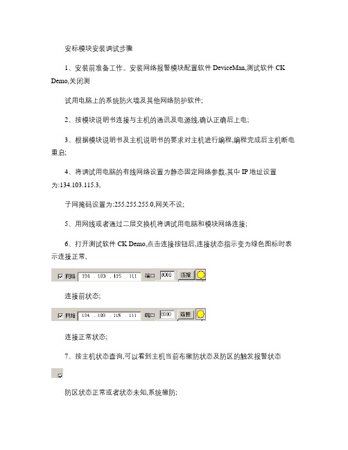
安装网络报警模块配置软件DeviceMan,测试软件CK Demo,关闭测试用电脑上的系统防火墙及其他网络防护软件;2、按模块说明书连接与主机的通讯及电源线,确认正确后上电;3、根据模块说明书及主机说明书的要求对主机进行编程,编程完成后主机断电重启;4、将调试用电脑的有线网络设置为静态固定网络参数,其中IP地址设置为:134.103.115.3,子网掩码设置为:255.255.255.0,网关不设;5、用网线或者通过二层交换机将调试用电脑和模块网络连接;6、打开测试软件CK Demo,点击连接按钮后,连接状态指示变为绿色图标时表示连接正常,连接前状态;连接正常状态;7、按主机状态查询,可以看到主机当前布撤防状态及防区的触发报警状态防区状态正常或者状态未知,系统撤防;防区回路触发,撤防状态时红外防区触发时将会随机变化电源正常,系统准备好系统设防,防区报警8、根据主机布撤防命令,在测试软件上按与真实键盘上相同的操作命令测试是否可以正常布撤防,以及测试软件上的布撤防状态与主机上的状态是否及时同步;(CP816布撤防:1234+ Enter;4110DL布防12342撤防12341;ST2008布撤防1111。
1234和1111为密码,现场以使用密码替代9、防区报警测试。
触发24小时防区或者布防后触发防区测试;(根据现场情况可以不测试10、用配置软件DeviceMan找到当前测试的模块后,按现场网管员提供的网络参数配置模块的IP,掩码,网关,串口1参数中的服务器IP地址和端口号。
服务器IP和端口号根据监控系统软件的要求设置,模块IP与服务器IP在同一子网时网关必须改为0.0.0.0。
(也可以通过IE访问模块IP进行网络配置参数的修改,修改后必须返回到主菜单按Apply Configuration重启应用新的网络参数。
11、与中心服务器软件确认模块已经连接成功,布撤防状态与现场主机同步后安装调试结束。
会议系统安装与调试方案

会议系统安装与调试方案目录1编制依据 (1)2工程概况 (2)2.1设计概况 (2)2.2水文、气象 (3)3施工重难点分析 (3)4施工进度计划和进度保证措施 (4)5施工组织 (5)5.1施工管理组织机构 (5)5.2资源配置计划 (6)5.2.1劳动力计划 (6)5.2.2施工机具 (6)6施工工艺技术 (7)6.1总体施工方案介绍 (7)6.2总体施工顺序 (8)6.3施工准备 (8)6.4作业条件 (9)6.5关键技术要求 (9)6.6质量关键要求 (9)6.7职业健康安全关键要求 (10)6.8施工工艺 (10)6.8.1拆除旧系统 (10)6.8.2机房放线 (10)6.8.3线管与线槽敷设 (10)6.8.4搭设脚手架 (14)6.8.5会议及扩声系统设备安装 (14)6.8.6会议及扩声系统调试 (21)7质量保证措施 (22)7.1质量保证体系 (22)7.2质量保证措施 (22)8安全保证措施 (23)8.1安全保证体系 (23)8.2安全保证措施 (25)8.2.1安全用电措施 (25)8.2.2高处作业安全措施 (26)8.2.3防火安全管理措施 (26)8.2.4做好高空落物防物体打击保护 (27)8.2.5做好高空作业安全管理 (27)9.文明施工和环境保护措施 (28)9.1文明施工 (28)9.2环境保护措施 (28)10.高温下施工措施 (29)会议系统安装与调试方案1编制依据1.1国家及相关部委颁布的法律、法规和现行设计规范和施工规范及其它有关文件资料。
具体有:-1、《民用建筑电气设计规范》JGJ/T16-92-2、《会议系统的电及其音频性能要求》GB/T15381-94-3、《施工现场临时用电安全技术规范》 JGJ46-2005-4、《厅堂扩声系统声学特性指标》广电部标准GYJ25-86-5、《厅堂扩声特性测量方法》国家标准GB/T4959-1995-6、《歌舞厅扩声系统的声学特性指标与测量方法》文化部标准WH0301-93-7、《厅堂混响时间测量规范》GBJ76-841.2援苏丹友谊厅维修项目施工图纸及有关设计文件、1.3与建设单位签订的合同、招标投标文件及我单位关于标准化管理文件的相关要求。
t.c.electronic M3000 快速操作指南_2011.06
t.c c.ele ectro onic M3快速操3000操作指南南一. 前面1. 电源开按住此键2. PC ‐CA将预置复3. SETUPI/O ‐ 输ROUTIN LEVELS UTIL/M面板相关英开关键保持1秒以ARD 存储卡复制到存储卡P ‐ 设置 输入、输出设NG ‐ 路径(T ‐ 电平(AUT IDI ‐多功能英文的解释:以上可以关闭卡槽 卡内,或将预设置(HELP ‐ TUNER ‐ 调谐TO LEVEL ‐ 自能/MIDI (MID :闭设备。
预置从存储卡帮助功能,谐,需要用S 自动电平调节I MONITOR‐卡内复制到设需要用SHIFT SHIFT 键切换节,需要用S MIDI监控,设备内。
T 键切换)换)SHIFT 键切换需要用SHIF ) FT 键切换)4.ENGIINE 1 ‐ 引擎1RECALL ‐ 效果调用(WIZARD ‐ 效果快速查询,需要用SHIFT键切换)STORE ‐ 效果存储(DELETE PRESET ‐ 删除预设置,需要用SHIFT键切换) EDIT ‐ 效果编辑BYPASS ‐ 效果旁路5.ENGIINE 2 ‐ 引擎2RECALL‐ 效果调用(WIZARD ‐ 效果快速查询,需要用SHIFT键切换)STORE ‐ 效果存储(DELETE PRESET ‐ 删除预置,需要用SHIFT键切换) EDIT ‐ 效果编辑BYPASS ‐ 效果旁路BINED 1+2 ‐ 组合引擎1和2RECALL ‐ 效果调用(WIZARD ‐ 效果快速查询,需要用SHIFT键切换)STORE ‐ 效果存储(DELETE PRESET ‐ 删除预设置,需要用SHIFT键切换) EDIT ‐ 效果编辑BYPASS ‐ 效果旁路7.SNAPSHOTS ‐ 快照存储或快速存储STORE 1 ‐ 快速存储1STORE 2 ‐ 快速存储2STORE 3 ‐ 快速存储3STORE 4 ‐ 快速存储48.CONTROL ‐ 控制部分OK ‐ 确认控制(CANCEL ‐ 取消控制,需要用SHIFT键切换) SHIFT ‐ 主控功能及蓝色二级功能切换键CURSOR ‐ 找寻PAGE UP ‐ 向上翻页PAGE DOWN ‐ 向下翻页TAP ‐ 节拍键ADJUST ‐ 数据轮二. 有关单击ROUTINt.c.electronic关t.c.elect NG (路径)键c M3000共tronic M 键进行路径的共有6种路径M3000的6的选择。
- 1、下载文档前请自行甄别文档内容的完整性,平台不提供额外的编辑、内容补充、找答案等附加服务。
- 2、"仅部分预览"的文档,不可在线预览部分如存在完整性等问题,可反馈申请退款(可完整预览的文档不适用该条件!)。
- 3、如文档侵犯您的权益,请联系客服反馈,我们会尽快为您处理(人工客服工作时间:9:00-18:30)。
TME安装调试指南内部资料请勿外传日期:2006年4月10日目录第一章:硬件系统安装第二章:软件编程第三章:条码枪安装第四章:打印机安装第五章:套筒选择器安装第一章硬件系统安装1.系统概述电动工具系统由拧紧控制箱、电缆和电动工具构成键盘认识:上面两个圆的区域内为状态指示灯,下面两个圆部分为键盘键盘部分细图2.检查下列部件是齐全:控制箱一个、电缆一条、电源线一条、工具一把3.系统连接1)连接工具和电缆:电缆的凸台和工具尾部的凹槽对齐,拧紧外面的大螺帽;2)把工具电缆连接到控制箱上:对齐电缆和控制箱工具接口上的凹槽和凸台,拧紧即可;3)连接电源:把电源线连接到控制箱的插口上4)检查各个连接是否牢靠;5)把电源连接到工厂的电源插座上;6)打开电源,开动电枪系统:把下图所示意的旋钮扳到“ON:位。
注意事项:更换电枪;重新连接其他部件必须关掉电源。
第二章Basic编程1.概述作为电枪系统,客户一般要求两步拧紧,使用控制软件中的Basic进行编程即可完成两步的扭矩控制或角度控制,下面举例说明软件设置的步骤。
2.扭矩法软件设置:扭矩控制,角度监控在客户处称为扭矩法控制,一般要求如下:加工某零件,要求扭矩大小5+/-1牛米(即4-6牛米,中值5牛米),扭矩控制,角度监控;2.1进入变成主界面:打开电枪后,按控制箱表面的导航按钮(下图红色圈部分按钮),进入编程主界面(如下图所示)电枪系统在任何情况下,只要按动导航按钮都会进入编程主界面。
2.2 确认电动工具型号注意:每次电枪和控制箱重新连接后,必须执行此步骤。
使用控制箱表面的上下左右按钮,输入按钮,选择工具安装(ToolSetup)。
中间为输入(Enter)按钮Tool Setup 呈现灰色表示选择,按Enter 进入,呈现下列界面工具型号得到确认:如上图为47EA43AM3 2.3 按导航轮回到主界面,选择Basic按“enter“进入编程界面参数设置:使用控制面板的上下左右按钮,enter 键,数字键盘完成下列设置1)选择Torque Control/Angle Monitor (扭矩控制/角度监测);当需要角度控制时这里可以选择Angle Control/Torque Monitor (角度控制/扭矩监测)此处为一个下拉菜单,可以进行选择。
2)填写扭矩上限:6NM3)填写扭矩中值:5NM4)填写扭矩下限值:4NM5)填写Threshold (start angle)此数值在0到工具扭矩最大值之间,一般为扭矩中值50%附近。
6)填写第一阶段扭矩结束值Turn off Torque Stage 1此数值在0到工具扭矩最大值之间,可以根据实际情况自由选择。
7)填写Trigger (start Scope)此数值在0到工具扭矩最大值之间,一般为最终扭矩中值的10%。
8)填写Stage 1 Speed (第一阶段速度)一般为工具空转转速的80%9)填写Stage 2Speed (第2阶段速度)通常设为50.10) 填写角度监控下限Angle Low Limit根据客户要求,没有要求设置为0。
11) 填写角度监控上限Angle High Limit根据客户要求,没有要求设置为9999。
至此,扭矩法控制的电枪设置完成。
当选择导航键退出时,需要确认所有的修改,Accept即可第三章Standard编程当需要大于两步的拧紧或特殊的拧紧步骤时,采用Standard编程最多可以设置6个步骤,通过Select SEQ每个步骤可以选用不同的拧紧策略,通过Parameters可以设置具体的参数;在Back off using reverse switch这里也可设置反转速度(反转开关打开时);当拧紧左旋螺栓时只需勾上Counter Clockwise;在Parameters菜单里可以设置参数或更改拧紧策略;进入Advanced就可设置一些其他的参数,如最大拧紧时间(Max Fastening)第四章Advanced编程4.1 Advanced内共有六个子菜单:Matrix只是显示拧紧程序的列表;共可预设255个Application;4.2 Input:共有8个输入点,每个点可分别定义,其中程序选择(Appl. Select)是BCD码位选,当需通过输入口外部选择程序时使用;接线方法如下:使用内部24V电源时:使用外部24V电源时:4.3 Output:共有8个输出点,每个点可分别定义;接线方法如下:使用内部24V电源时:使用外部24V电源时:注意:TMEM控制器的输出无法直接使用外部24V电源,因为它的PIN1和PIN2在内部已经短接了,要想使用外部电源必须通过继电器。
4.4 Fieldbus只有在使用总线时才需编辑。
4.5 Linking组功能共可设8个程序组,可分别起名字;每个组内最多可集成96个Application,当需要激活组功能时将Enabled设为Yes;Reset after NOK为Yes时每当出现不合格,计数清零,从组内第一个螺栓重新打起,所以常设为No;No. of Repeats NOK是不合格后须重新拧紧的次数,如设为5即某个螺栓拧紧不合格时须重拧5次,如第5次重拧还不合格将自动跳过,拧下一个螺栓,组结束后将标记为Linking NOK。
组建组时只需将需要的Application 号填入,然后用Add键插入组内相应的位置即可。
4.6 System Settings系统设置这里可以为系统命名和编号,Same for both tools只在双通道控制箱使用;Max Number of Rejects是最大返修次数,当达到最大次数时枪会锁住,只有提供Release信号才可解锁,当设为0时此功能无效;Release 的方法可以是枪上的反转开关或Input上输入Release信号。
Torque units是设定扭矩单位的。
Tool Sync/Disable Linking同步功能激活/同时组功能实效NOK if start switch release当启动按钮在拧紧时如放掉即不合格Archive only if Torque>Trigger只有扭矩大于Trigger时才将数据归档External Application Select从Input外部输入选择Application或Group External Tool enable当选中时只有从Input输入Tool enable 工具才能启动Latched Remote Start选中时从Input输入一个脉冲信号到Remote Start就能启动工具直到一次拧紧结束Blinking Lights in Reverse选中时每当反转开关打开,所有指示灯会闪亮(TMEM无此功能)第五章Run Screen运行界面5.1 在Run Screen里可以实时显示拧紧的扭矩、角度等数据和状态,这是一般在拧紧工作时打开的一个界面,绿色表示合格;5.2 在Run Screen界面可进入Print(打印)、Oscilloscope(拧紧曲线)、Configure(设置)、Help(帮助)这四个子菜单,Oscilloscope(拧紧曲线)能显示拧紧过程中以角度和扭矩为坐标的曲线;其中Configure(设置)菜单能对Run Screen界面进行设置:在双通道控制器如选择Split Screen,就能同时显示两个通道的画面:第六章Communications通讯6.1 Data Transmission 数据传输拧紧数据如扭矩角度等能通过串口或以太网传输;如通过串口传输,须在Serial界面里设置:1.Protocol(协议):我们配有6种串口传输协议可供选择;比如下面是其中之Standard 2的协议:2.Port (串口):选择两个Serial Port(串口)中的一个3.Baud Rate(波特率) 等串口参数的设定须与所通讯的串口设备一致。
如通过以太网口传输数据,须在Ethernet界面里设置:1.Protocol(协议):我们配有4种标准网口传输协议可供选择;如要与Torque Data System软件通讯,设成Standard;2.还须设置网络地址等其他参数:Server:需接受拧紧数据的服务器网络地址Gateway:网关地址(如有网关)TM Unit:控制器自己的网络地址Subnet:子网掩码Port:如要与Torque Data System软件通讯,设成1500 MAC:控制器物理地址,自动生成无需设置6.2 Part ID 条码号或零件号1.设置Enable选项此选项为一个下拉菜单,有四个选项:Disable:此项功能关闭Enable:功能激活Enable interlocked:功能激活并且在拧紧前必须有效零件号输入,否则无法启动工具Printer Interlocked.:功能激活并且拧紧前必须有效零件号输入,否则无法启动工具,拧紧结束后如按“F1”打印结果后工具会锁住,等待下一个有效零件号输入2.设置Part ID Resource此选项选择零件号的来源,选择有三个选项:Serial Port:串口设备输入如条码扫描枪(注意:如使用条码扫描枪必须是串口扫描枪)Fieldbus:现场总线输入Protocol:以太网络输入3.设置零件号的长度(Number of Charcters):最长25个字符4.设置是否允许键盘手工输入件号(Keypad Entry)5.设置Data Function 选项此选项用于决定电枪选用程序是否受到零件号的控制,如果受控制,选择Configure Data ,如果不受控制,选择None.如选择了Configure Data,下方的Configure Data子菜单会变成亮色,可以进入进行设置;如上举例:当零件号第1位为2时选用程序组2,用Add键添加,Delete键删除。
6.3 Printer打印机在并口上连接打印机注意:接口是25针当Parallel Enable: 选择后,数据够一页后就发送到打印机自动打印提示:1.可以按控制箱上的F1键手动打印;2. 最好先开打印机再开控制箱Filter :过滤数据,由三个选项,All, Ok,Nok 含义如下表Array Port : 只有一个选项Centronics第七章Tool Setup工具设置在Tool Setup界面中可看到工具的详细信息,包括型号、序列号参数、维修信息等。
其中Torque Cal.是表示扭矩传感器的比例参数,是可以人工修改的,如枪的真实扭矩偏低则改小,真实扭矩偏高则改大。
第八章Statistics统计8.1 Chronological History历史记录用户可以通过历史记录查看所有的拧紧数据,也可通过Parameter 和Graphs对数据进行检索。