机械图纸中常见的符号及意义
形位公差符号大全

形位公差符号大全形位公差是机械制造中常见的一种公差,它用来描述零件的形状和位置的偏差范围,是保证零件装配和工作精度的重要手段。
形位公差的表示方法主要有两种,一种是采用ISO标准的形位公差符号,另一种是采用国家标准的形位公差符号。
在实际的工程设计和制造中,了解和掌握形位公差符号的含义和应用是非常重要的。
本文将对形位公差符号进行全面详细的介绍,希望能够为广大工程技术人员提供一些帮助和参考。
1. 直线度公差。
直线度公差是用来描述直线轴线的偏离程度的公差,其符号为⊥。
在图纸上表示为⊥0.1,表示直线轴线的偏差范围为0.1。
直线度公差的应用范围非常广泛,特别是在需要保证零件装配精度和工作精度的场合,直线度公差的控制显得尤为重要。
2. 平面度公差。
平面度公差是用来描述平面表面的偏离程度的公差,其符号为△。
在图纸上表示为△0.05,表示平面表面的偏差范围为0.05。
平面度公差在机械制造中也是一种常见的公差,尤其是对于需要保证平面密封性和工作精度的零件,平面度公差的控制至关重要。
3. 圆度公差。
圆度公差是用来描述圆形轴线的偏离程度的公差,其符号为◎。
在图纸上表示为◎0.02,表示圆形轴线的偏差范围为0.02。
圆度公差在轴类零件的制造中非常常见,对于需要保证轴类零件的转动精度和配合精度的场合,圆度公差的控制尤为重要。
4. 同轴度公差。
同轴度公差是用来描述轴线同一直线上的偏离程度的公差,其符号为∥。
在图纸上表示为∥0.03,表示轴线同一直线上的偏差范围为0.03。
同轴度公差在需要保证零件装配精度和工作精度的场合也是一种常见的公差。
5. 同心度公差。
同心度公差是用来描述轴孔中心和轴线中心的偏离程度的公差,其符号为⊙。
在图纸上表示为⊙0.04,表示轴孔中心和轴线中心的偏差范围为0.04。
同心度公差在需要保证轴类零件的配合精度和工作精度的场合也是一种常见的公差。
6. 垂直度公差。
垂直度公差是用来描述两个垂直面的偏离程度的公差,其符号为⊥。
机械图纸解析,看懂了它,所有的图纸都能轻松看懂(干货)
机械图纸解析,看懂了它,所有的图纸都能轻松看懂(干货)1.纸幅面按尺寸大小可分为5种,图纸幅面代号分别为A0、A1、A2、A3、A4。
图框右下角必须要有一标题栏,标题栏中的文字方向为与看图方向一致。
2.图线的种类有粗实线、细实线、波浪线、双折线、虚线、细点划线、粗点划线、双点划线等八类。
3.图样中,机件的可见轮廓线用粗实线画出,不可见轮廓线用虚线画出,尺寸线和尺寸界线用细实线画出来,对称中心线和轴线用细点划线画出。
虚线、细实线和细点划线的图线宽度约为粗实线的1/3。
4.比例是指图中图形尺寸与实物尺寸之比。
5.比例1:2是指实物尺寸是图形尺寸的2倍,属于缩小比例。
6.比例2:1是指图形尺寸是实物尺寸的2倍,属于放大比例。
7.在画图时应尽量采用原值比例的比例,需要时也可采用放大或缩小的比例,其中1:2为缩小比例,2:1为放大比例无论采用那种比例图样上标注的应是机件的实际尺寸。
8.图样中书写的汉字、数字和字母,必须做到字体工整,笔画清楚,间隔均匀,排列整齐,汉字应用长仿宋体书写。
9.标注尺寸的三要素是尺寸界限、尺寸线、尺寸数字。
10.尺寸标注中的符号:R表示圆半径,ф表示圆直径,Sф表示球直径。
11.图样上的尺寸是零件的实际尺寸,尺寸以毫米为单位时,不需标注代号或名称。
12.标准水平尺寸时,尺寸数字的字头方向应向上;标注垂直尺寸时,尺寸数字的字头方向应朝左。
角度的尺寸数字一律按水平位置书写。
当任何图线穿过尺寸数字时都必须断开。
13.斜度是指斜线对水平线的倾斜程度,用符号∠表示,标注时符号的倾斜方向应与所标斜度的倾斜方向一致。
所标锥度方向一致。
14.符号“∠1:10”表示斜度1:10,符号“ 1:5”表示锥度1:5。
15.平面图形中的线段可分为已知线段、中间线段、连接线段三种。
它们的作图顺序应是先画出已知线段,然后画中间线段,最后画连接线段。
16.已知定形尺寸和定位尺寸的线段叫已知线段;有定形尺寸,但定位尺寸不全的线段叫中间线段;只有定形尺寸没有定位尺寸的线段叫连接线段。
机械图纸中常见的符号及意义
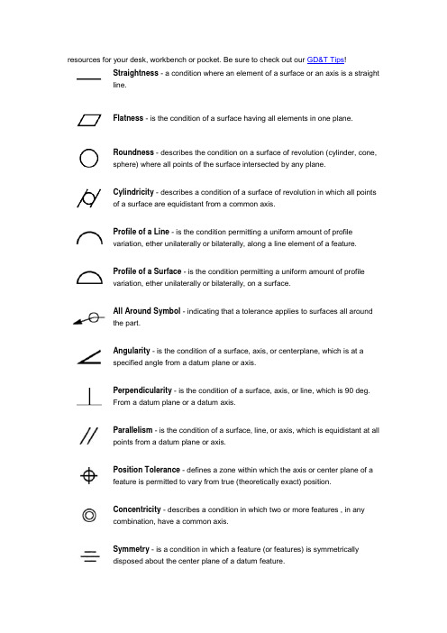
resources for your desk, workbench or pocket. Be sure to check out our GD&T Tips!Straightness - a condition where an element of a surface or an axis is a straightline.Flatness - is the condition of a surface having all elements in one plane.Roundness - describes the condition on a surface of revolution (cylinder, cone, sphere) where all points of the surface intersected by any plane.Cylindricity - describes a condition of a surface of revolution in which all points of a surface are equidistant from a common axis.Profile of a Line - is the condition permitting a uniform amount of profile variation, ether unilaterally or bilaterally, along a line element of a feature.Profile of a Surface - is the condition permitting a uniform amount of profile variation, ether unilaterally or bilaterally, on a surface.All Around Symbol - indicating that a tolerance applies to surfaces all around the part.Angularity - is the condition of a surface, axis, or centerplane, which is at a specified angle from a datum plane or axis.Perpendicularity - is the condition of a surface, axis, or line, which is 90 deg. From a datum plane or a datum axis.Parallelism - is the condition of a surface, line, or axis, which is equidistant at all points from a datum plane or axis.Position Tolerance - defines a zone within which the axis or center plane of a feature is permitted to vary from true (theoretically exact) position.Concentricity - describes a condition in which two or more features , in any combination, have a common axis.Symmetry - is a condition in which a feature (or features) is symmetrically disposed about the center plane of a datum feature.Runout - is the composite deviation from the desired form of a part surface of revolution through on full rotation (360 deg) of the part on a datum axis.Total Runout - is the simultaneous composite control of all elements of a surface at all circular and profile measuring positions as the part is rotated through 360.Maximum Material Condition (MMC) - is that condition of a part feature wherein it contains the maximum amount ofmaterial within the stated limits of size. That is: minimum hole size and maximum shaft size.Least Material Condition (LMC) - implies that condition of a part feature of size wherein it contains the least (minimum) amount of material, examples, largest hole size and smallest shaft size. It is opposite to maximum material condition.Regardless Of Feature Size (RFS) - the condition where the tolerance of form, runout or location must be met irrespective of where the feature lies within its size tolerance.Projected Tolerance Zone - applies to a hole in which a pin, stud, screw, etc., is to be inserted. It controls the perpendicularity of the hole to the extent of the projection from the hole and as it relates to the mating part clearance. The projected tolerance zone extends above the surface of the part to the functional length of the pin, stud, and screw relative to its assembly with the mating part.Tangent Plane - indicating a tangent plane is shown. The symbol is placed in the feature control frame following the stated tolerance.Free State Variations - is a term used to describe distortion of a part after removal of forces applied during manufacture.Diameter - indicates a circular feature when used on the field of a drawing or indicates that the tolerance is diametrical when used in a feature control frame.Basic Dimension - used to describe the exact size, profile, orientation or location of a feature. A basic dimension is always associated with a feature control frame or datum target. (Theoretically exact dimension in ISO)Reference Dimension - a dimension usually without tolerance, used for information purposes only. It does not govern production or inspection operations. (Auxiliary dimension in ISO)Datum Feature - is the actual component feature used to establish a datum.Dimension Origin - Signifies that the dimension originates from the plane established by the shorter surface and dimensional limits apply to the other surface.Feature Control Frame - is a rectangular boxcontaining the geometric characteristics symbol, andthe form, runout or location tolerance. If necessary,datum references and modifiers applicable to thefeature or the datums are also contained in the box.Conical Taper - is used to indicate taper for conical tapers. This symbol is always shown with the vertical leg to the left.Slope - is used to indicate slope for flat tapers. This symbol is always shown with the vertical leg to the left.Counterbore/Spotface - is used to indicate a counterbore or a spotface. The symbol precedes the dimension of the counterbore or spotface, with no spaceCountersink - is used to indicate a countersink. The symbol precedes the dimensions of the countersink with no space.Depth/Deep - is used to indicate that a dimension applies to the depth of a feature. This symbol precedes the depth value with no space in between.Square - is used to indicate that a single dimension applies to a square shape. The symbol precedes the dimension with no space between.Number of Places - the X is used along with a value to indicate the number of times a dimension or feature is repeated on the drawing.Arc Length - indicating that a dimension is an arc length measured on a curved outline. The symbol is placed above the dimension.Radius - creates a zone defined by two arcs (the minimum and maximum radii). The part surface must lie within this zone.Spherical Radius - precedes the value of a dimension or tolerance.Spherical Diameter - shall precede the tolerance value where the specified tolerance value represents spherical zone. Also, a positional tolerance may be used to control the location of a spherical feature relative to other features of a part. The symbol for spherical diameter precedes the size dimension of the feature and the positional tolerance value, to indicate a spherical tolerance zone.Controlled Radius - creates a tolerance zone defined by two arcs (the minimum and maximum radii) that are tangent to the adjacent surfaces. Where a controlled radius is specified, the part contour within the crescent-shaped tolerance zone must be a fair curve without flats or reversals. Additionally, radii taken at all points on the part contour shall neither be smaller than the specified minimum limit nor larger than the maximum limit.Between - to indicate that a profile tolerance applies to several contiguous features, letters may designate where the profile tolerance begins and ends. These letters are referenced using the between symbol (since 1994) or the word between on drawings made to earlier versions of the Standard.Statistical Tolerance - i s the assigning of tolerances to related components of an assembly on the basis of sound statistics (such as the assembly tolerance is equal to the square root of the sum of the squares of the individual tolerances). By applying statistical tolerancing, tolerances of individual components may be increased or clearances between mating parts may be reduced. The increased tolerance or improved fit may reduce manufacturing cost or improve the product's performance, but shall only be employed where the appropriate statistical process control will be used. Therefore, consideration should be given to specifying the required Cp and /or Cpk or other process performance indices.Datum Target - is a specified point, line, or area on a partthat is used to establish the Datum Reference Plane formanufacturing and inspection operations.Target Point - indicates where the datum target point is dimensionally located on the direct view of the surface.。
轴圆度符号
轴圆度符号全文共四篇示例,供读者参考第一篇示例:轴圆度符号是机械制图中常见的一种符号,用于表示零件轴线的圆度要求。
轴圆度符号通常由一个圆形符号和一个字母“C”组成,圆形符号代表轴线,字母“C”表示圆度。
轴圆度符号的出现使得工程师能够清晰地了解零件的轴线要求,有利于工厂生产和质检时的操作。
轴圆度符号的设计遵循ISO标准,具体形状和大小根据零件的实际情况而定。
在机械制图中,轴圆度符号通常放置在零件尺寸的旁边,以示明确轴线的圆度要求。
通常情况下,轴圆度符号后面会跟随一个具体的数值,表示轴线的最大允许偏差值。
在工程设计和制造中,轴圆度符号扮演着非常重要的角色。
通过轴圆度符号,工程师可以明确了解零件轴线的圆度要求,避免在生产和使用过程中出现尺寸偏差过大的问题。
正确理解和应用轴圆度符号,有助于提高产品的质量和可靠性,降低生产成本,提高生产效率。
除了轴圆度符号,机械制图中还有许多其他符号用于表示不同的尺寸要求,如平行度符号、垂直度符号等。
这些符号在工程设计和生产中都起着至关重要的作用,帮助工程师们更加准确地表达设计意图,确保产品的尺寸精度和质量稳定性。
轴圆度符号是机械制图中的重要符号之一,它为工程师们提供了清晰明了的轴线圆度要求,有助于提高零件生产质量和生产效率。
正确应用轴圆度符号,关注尺寸精度和质量稳定性,是每个工程师都应该具备的基本能力。
希望通过本文的介绍,读者们能够更加深入地了解轴圆度符号的意义和作用,为工程设计和制造提供更多的帮助。
第二篇示例:轴圆度符号是一个在工程图纸中常见的符号,用于指示零件轴线的圆度要求。
轴圆度是一个零件在其轴线上的任意截面上离轴线的距离的最大值和最小值之间的差值。
轴圆度符号通常是一个半圆和一条直线组成的符号,其中半圆表示零件的轴线的最大可能圆度,直线表示轴线的位置。
在工程设计和制造中,轴圆度符号是非常重要的。
通过使用轴圆度符号,设计师可以准确地指示零件的轴线的要求,并确保零件在装配和使用时具有稳定的性能。
机械图纸解析,看懂了它,所有的图纸都能轻松看懂(干货)
机械图纸解析,看懂了它,所有的图纸都能轻松看懂(干货)1.纸幅面按尺寸大小可分为5种,图纸幅面代号分别为A0、A1、A2、A3、A4。
图框右下角必须要有一标题栏,标题栏中的文字方向为与看图方向一致。
2。
图线的种类有粗实线、细实线、波浪线、双折线、虚线、细点划线、粗点划线、双点划线等八类。
3.图样中,机件的可见轮廓线用粗实线画出,不可见轮廓线用虚线画出,尺寸线和尺寸界线用细实线画出来,对称中心线和轴线用细点划线画出。
虚线、细实线和细点划线的图线宽度约为粗实线的1/3。
4.比例是指图中图形尺寸与实物尺寸之比。
5.比例1:2是指实物尺寸是图形尺寸的2倍,属于缩小比例.6.比例2:1是指图形尺寸是实物尺寸的2倍,属于放大比例。
7。
在画图时应尽量采用原值比例的比例,需要时也可采用放大或缩小的比例,其中1:2为缩小比例,2:1为放大比例无论采用那种比例图样上标注的应是机件的实际尺寸。
8.图样中书写的汉字、数字和字母,必须做到字体工整,笔画清楚,间隔均匀,排列整齐,汉字应用长仿宋体书写。
9.标注尺寸的三要素是尺寸界限、尺寸线、尺寸数字.10。
尺寸标注中的符号:R表示圆半径,ф表示圆直径,Sф表示球直径。
11。
图样上的尺寸是零件的实际尺寸,尺寸以毫米为单位时,不需标注代号或名称。
12.标准水平尺寸时,尺寸数字的字头方向应向上;标注垂直尺寸时,尺寸数字的字头方向应朝左。
角度的尺寸数字一律按水平位置书写。
当任何图线穿过尺寸数字时都必须断开.13.斜度是指斜线对水平线的倾斜程度,用符号∠表示,标注时符号的倾斜方向应与所标斜度的倾斜方向一致。
所标锥度方向一致。
14。
符号“∠1:10"表示斜度1:10,符号“ 1:5"表示锥度1:5.15。
平面图形中的线段可分为已知线段、中间线段、连接线段三种。
它们的作图顺序应是先画出已知线段,然后画中间线段,最后画连接线段。
16.已知定形尺寸和定位尺寸的线段叫已知线段;有定形尺寸,但定位尺寸不全的线段叫中间线段;只有定形尺寸没有定位尺寸的线段叫连接线段。
机械制图中常见的符号及意义
周围标志-表明公差适用于所有周围的部分表面。
倾斜度-是表面,轴,或中线,这是从某一特定角度基准平面或轴。
垂直度-条件是表面,轴,或线,这是90度的基准平面或基准轴
平行度-一个表面,线,或轴,这是等距离的所有点,基准平面或轴。
位置公差-定义一个区域内的轴或中心平面的一个特点是允许不同的真正的(理论上精确)位置。
相同的地方-是用来与一个值显示的次数维度或特征是反复的绘制。
电弧长度-表明,维弧长度测量曲面轮廓。符号放在上面的维度。
半径-创建一个区域定义的弧(最大和最小半径)。零件表面必须躺在这个区域。
δ
厚度新代词(t)
球面半径-之前的价值维度或耐受性。
EQS
均布-平均分布到某各部位
球形直径公差值-前应在指定的公差值代表球区。此外,一个位置公差可能被用来控制的位置,一个球形特征相对于其他特征的一部分。符号为球形直径之前的尺寸大小的特征和位置公差值,表明一个球形公差带
控制半径-创造了一个宽容的定义双圆弧(最大和最小半径),切向相邻表面。其中一个控制半径是指定的,部分轮廓公差带内的月牙形必定是一个公平的曲线没有单位或逆转。此外,半径在所有点上的部分轮廓不应小于规定的最低限额也不大于最大限度。
C
45°倒角
之间-表明一个外形公差适用于几个连续的功能,可以指定在外形公差的开始和结束。这些信件是参考使用符号(1994)或词之间的图纸发到早期版本的标准。
统计公差-是分配公差相关装配部件的基础上,统计(如装配公差等于平方根的平方和个别公差)。应用统计公差,公差个别组件可以增加或间隙配合的零件可减少。增加容忍或改进适合可能降低制造成本和提高产品的性能,但只应在适当的统计过程控制将被使用。因此,应考虑到指定所需的处长和/或血清或其他过程性能指数。
机械图纸中常见的符及意义中文定稿版
机械图纸中常见的符及意义中文HUA system office room 【HUA16H-TTMS2A-HUAS8Q8-HUAH1688】resources for your desk, workbench or pocket. Be sure to check out our GD&T Tips!直度-一个条件,一个面元素或轴是一条直线。
平整度-是条件,表面有所有的元素在一个平面。
圆度-描述条件对革命的表面(圆柱,圆锥,球)在所有点的表面相交的任何飞机。
圆柱度-描述了一个条件的旋转面,使所有的点面距离相等,一个共同的旋转轴。
线轮廓度-是条件允许量相同的剖面变化,醚单边或双边,沿着一条线元素的特征。
面轮廓度-是条件允许量相同的剖面变化,醚单边或双边,上表面。
周围标志-表明公差适用于所有周围的部分表面。
倾斜度-是表面,轴,或中线,这是从某一特定角度基准平面或轴。
垂直度-条件是表面,轴,或线,这是90度的基准平面或基准轴平行度-一个表面,线,或轴,这是等距离的所有点,基准平面或轴。
位置公差-定义一个区域内的轴或中心平面的一个特点是允许不同的真正的(理论上精确)位置。
同心度-描述在其中一个条件的2个或更多的功能,在任何组合,有一个共同的旋转轴。
对称度 -是一种状况,其中一个功能(或功能)是处理有关对称中心平面基准特征。
跳动-是复合偏离理想形式的一部分表面上通过革命旋转(360度)的一部分,在基准轴全跳动-是同时复合控制所有表面元素在所有圆轮廓测量位置的部分是通过旋转360。
最大材料状态(三菱)-是条件的一部分功能其中包含的最高金额材料在规定的极限尺寸。
那就是:最小孔尺寸和最大轴尺寸。
最小材料状态(落马洲)-意味着条件的一部分功能的大小,其中也包含了最小(最低)的材料,例子,最大孔尺寸和最小轴径。
它的对面是最大材料状态。
不论大小的特征(范畴专题)-的情况下,形状公差,跳动或位置必须满足,不论在哪里,它的特点是在其尺寸公差。
滑动轴承基本符号
滑动轴承基本符号滑动轴承是一种常见的机械元件,用于减少摩擦和支撑旋转或直线运动。
在滑动轴承中,基本符号被广泛应用于技术图纸和说明书中,以便准确描述轴承的结构和性能特点。
本文将介绍滑动轴承的基本符号及其含义。
1. 轴承类型标识在滑动轴承的图纸和说明书中,常见的轴承类型标识包括以下几种:•B:表示滚动体式滑动轴承。
这种类型的轴承由内圈、外圈和滚动体组成,通过滚动体在内外圈之间运动来实现摩擦减少。
•P:表示法兰式薄壁滑动轴承。
这种类型的轴承具有较小的截面尺寸,适用于有限空间和重量要求较高的场合。
•F:表示平面式薄壁滑动轴承。
这种类型的轴承具有平整的内外表面,在平面上进行相对运动。
•S:表示球面式滑动轴承。
这种类型的轴承具有球面内外表面,可在球面上进行相对运动。
•T:表示推力式滑动轴承。
这种类型的轴承主要用于承受轴向负荷,通常由一组平行的垫片组成。
2. 轴承尺寸标识滑动轴承的尺寸标识一般以直径和宽度表示,常见的标识方法如下:•d:表示内圈直径。
内圈是与轴直接接触并旋转的部分。
•D:表示外圈直径。
外圈是与外壳接触并固定在其上的部分。
•B:表示宽度。
宽度指轴承沿着轴线方向的厚度或高度。
这些标识通常以毫米为单位,在技术图纸中使用字母和数字来表示具体数值。
例如,d=20mm、D=42mm、B=12mm 表示一个滑动轴承,其内圈直径为20mm,外圈直径为42mm,宽度为12mm。
3. 轴承材料标识滑动轴承的材料选择对其性能有重要影响,因此在图纸和说明书中需要标明所采用的材料。
常见的轴承材料标识如下:•S:表示钢制材料。
钢制滑动轴承具有较高的强度和承载能力,适用于一般工业应用。
•B:表示铜合金材料。
铜合金滑动轴承具有良好的耐磨性和导热性能,适用于高速和高温环境。
•P:表示聚合物材料。
聚合物滑动轴承具有自润滑性能和良好的抗腐蚀性能,适用于特殊工况和食品行业。
4. 轴承润滑方式标识润滑对于滑动轴承的正常运行至关重要,因此在图纸和说明书中需要标明所采用的润滑方式。
图纸中各种线条和符号的意义
图纸中各种线条和符号的意义
为了正确地看懂舰船模型的工作图纸,首先要熟悉图纸中各种线条和符号的意义。
图纸上常见的有粗实线、细实线、虚线、点划线、折断线和剖面线等。
粗实线:一般表示物体外表一切可见的轮廓线。
虚线:一般表示物体被遮挡的轮廓线。
细实线:一般表示物体的尺寸线、尺寸界限、引线和剖面线。
点划线:一般表示物体的中心线、位置线和轴线。
折断线:折断线或波浪线一般表示物体断开的地方。
有些不必要全部画出的地方,就可以采用折断线或波浪线的办法省略掉。
剖面线:一般表示物体剖视的地方。
图纸上常用的符号有M、d、R等。
M 表示比例尺。
比如Ml:100,表示图纸的尺寸是实物的百分之一。
机械制图国家标准中粗实线只有两种用途,即可见轮廓线、可见过渡线,虚线也只有两种用途,即不可见轮廓线、不可见过渡线,其余的可见线为细实线
图线
1)基本线型
根据国标GB/T 17450-1998《技术制图图线》,在机械制图中常用的线型有实线、虚线、点画线、双点画线、波浪线、双折线等。
2)图线的宽度
图线的宽度d应根据图形的大小和复杂程度,在下列数系中选择:0.18,0.25,0.35,0.5,0.7,1,1.4,2mm。
在机械图样上,图线一般只有两种宽度,分别称为粗线和细线,其宽度之比为2:1。
在通常情况下,粗线的宽度采用0.5或0.7 mm,细线的宽度采用0.25或0.35 mm。
在同一图样中,同类图线的宽度应一致。
投影视图。
机械图纸中常见的符号及意义
材料在规定的极限尺寸。那就是:最小孔尺寸和最大轴尺寸。
最小材料状态(落马洲)-意味着条件的一部分功能的大小,其中也包含了最小(最低)的材料,例子,最大孔尺寸和最小轴径。它的对面是最大材料状态。
投影公差区-适用于孔内的销,螺栓,螺钉,等等,是插入。它控制孔的垂直度的程度的预测从洞,因为它涉及到交配的一部分清除。投影公差区延伸高于地面的部分功能的针的长度,螺栓,螺钉相对于其组装与交配的一部分。
控制半径-创造了一个宽容的定义双圆弧(最大和最小半径),切向相邻表面。其中一个控制半径是指定的,部分轮廓公差带内的月牙形必定是一个公平的曲线没有单位或逆转。此外,半径在所有点上的部分轮廓不应小于规定的最低限额也不大于最大限度。
C
45°倒角
之间-表明一个外形公差适用于几个连续的功能,可以指定在外形公差的开始和结束。这些信件是参考使用符号(1994)或词之间的图纸发到早期版本的标准。
面轮廓度-是条件允许量相同的剖面变化,醚单边或双边,上表面。
周围标志-表明公差适用于所有周围的部分表面。
倾斜度-是表面,轴,或中线,这是从某一特定角度基准平面或轴。
垂直度-条件是表面,轴,或线,这是90度的基准平面或基准轴
平行度-一个表面,线,或轴,这是等距离的所有点,基准平面或轴。
位置公差-定义一个区域内的轴或中心平面的一个特点是允许不同的真正的(理论上精确)位置。
直度-一个条件,一个面元素或轴是一条直线。
平整度-是条件,表面有所有的元素在一个平面。
圆度-描述条件对圆柱度-描述了一个条件的旋转面,使所有的点面距离相等,一个共同的旋转轴。
线轮廓度-是条件允许量相同的剖面变化,醚单边或双边,沿着一条线元素的特征。
- 1、下载文档前请自行甄别文档内容的完整性,平台不提供额外的编辑、内容补充、找答案等附加服务。
- 2、"仅部分预览"的文档,不可在线预览部分如存在完整性等问题,可反馈申请退款(可完整预览的文档不适用该条件!)。
- 3、如文档侵犯您的权益,请联系客服反馈,我们会尽快为您处理(人工客服工作时间:9:00-18:30)。
机械图纸中常见的符号及意义《机械识图》根据最新的中等职业学校机械制图教学大纲,针对中等职业学校学生在识图知识与技能方面的就业需求编写而成,注重对中等职业学校学生的识图能力培养。
《图文对半,直观形象,方便教学。
全书共分9个项目:抄画平面图形,三视图的形成与投影作图,基本几何体的视图,绘制与识读组合体视图,识读视图、剖视图和断面图,识读轴套类零件图,识读盘盖轮类零件图,识读叉架类和箱壳类零件图,识读装配图。
通过这9个项目将知识点与任务有机地结合,由浅入深,循序渐进,使学生完成技能的训练,达到学以致用的目的。
自劳动开创人类文明史以来,图形与语言、文字一样,是人们认识自然、表达和交流思想的基本工具,在图学发展的历史长河中,经过不断地完善和发展得到了广泛的应用。
在现代工业生产中,机械、化工或建筑都是根据图样进行制造和施工的。
设计者通过图样表达设计意图;制造者通过图样了解设计要求、组织制造和指导生产;使用者通过图样了解机器设备的结构和性能,进行操作、维修和保养。
因此机械图样是交流传递技术信息、思想的媒介和工具,是工程界通用的技术语言。
作为职业技术教育培养目标的生产第一线的现代新型技能型人才,必须学会并掌握这种语言,具备识读和绘制机械图样的基本能力。
从以下几方面可以体现其重要性:从事机械制造行业就须掌握机械制图 ,学习机械制图感到抽象、困难,其原因之一是习惯于在平面上思考问题,缺乏空间思维能力。
在学习过程中教师要有针对性地借助各种媒体,直观、形象地引导学生建立起空间概念,由平面思维转换到空间思维。
把物体的投影与实际零件结构紧密联系,不断地“由物画图”和“由图画物”,既要想象物体的形状,又要思考图形间的投影规律,步提高空间想象和思维能力。
有了这种能力,在实际工作时,才会通过二维的平面图——零件图(或装配图)想象出来三维的空间物体——实际零件(装配体),只有掌握这种技能,才能顺利完成零件加工或机器装配的工作。
所以,空间想象能力是学习机械制图的核心内容。
《机械制图》的基本原理,制图标准、及相关规则,严肃体现出国家标准的统一性,无论谁都必须严格遵照执行。
随着我国各个领域与国际接轨的今天,在机械制造行业,国家标准与国际标准也会逐步一致,使我国机械制造行业技术人才能更好的与之交流,那么就必须熟练地掌握这门技术语言,更便于同行业间进行技术探讨和技术革新,但是前提条件是必须精通机械制图这门课程以及相关的国家标准,并且反复强调标准规定的严谨性、权威性和法制性,使技术人员较好地确立标准化意识。
机械制图对解决实际问题和创新能力的影响《机械制图》课除了如何使他们很好地建立空间想象能力、掌握投影规律及国家标准,还必须具有机械专业的相关知识,如金属工艺学、机械制造工艺学、机械零件与机械原理、公差配合与技术测量等,这些知识在机械制图中的零件结构、表面质量、加工方法、材料选择、技术要求、连接装配关系等方面都要用到。
也不是只局限于了解制图上的一些概念、定义和规则,还会学习和掌握到其它相关领域的各种知识,并且会正确、合理、全面地应用好机械制图这门工具,是现代化生产中技术人才最基本的要求,通过机械制图的学习,就要求具备这种让机械制图与实际结合起来,解决实际工作中存在的各方面的问题的能力。
《机械制图》是人们进行技术革新、技术改造的工具,是对新设计、新构思、新工艺研究探索,反映和表达高新技术、发明创造新生事物的载体。
大胆地在该课程教学中融进新思想、新设计、探索和创新,是知识经济时代向我们提出的新课题、新挑战。
我们在教学全过程中始终注意贯彻这一主导思想。
激励大家勤于动脑,勇于探索,敢于创新,逐步形成了创新观念,创新意识,培养了学生的创新思维能力。
如此较长时间,多个阶段的激发培养,让学生对《机械制图》课程的知识点,发生飞跃的认识,培养起创造能力与个性品质,在今后实际生产中进行技术革新、机械设计时起到要作用。
在加工制造中零件图和装配图的作用 ,任何一台机器或一个部件都是由若干零件装配而成的,制造机器首先要依据零件图加工零件,再根据装配图,组装成机器或者部件。
零件图是制造和检验零件的主要依据,不会识读零件图,根本无从着手加工零件,所以,识读零件图和绘制零件图是《机械制图》的重要内容。
能快速而正确地识读零件的图纸,理解零件的加工信息,是正确实施零件加工的前提,能合理表达零件的结构,正确规范的绘制一张零件的图纸,是在职业岗位上进行技术交流和沟通的必要手段。
另外机器或者部件的设计过程中,一般先根据设计要求画出装配图以表达机器或者部件的工作原理、传动路线,零件之间的装配关系以及零件的结构形状,然后按照装配图设计零件,并绘制零件图。
再生产过程中,装配图又是制定机器或部件装配工艺规程、指导装配、检验、安装和维修的依据。
因此识读装配图是在生产交流和技术革新中重要的一项读图能力Straightness - a condition where an element of a surface or an axis is astraight line.Flatness - is the condition of a surface having all elements in one plane.Roundness - describes the condition on a surface of revolution (cylinder,cone, sphere) where all points of the surface intersected by any plane.Cylindricity - describes a condition of a surface of revolution in which allpoints of a surface are equidistant from a common axis.Profile of a Line - is the condition permitting a uniform amount of profile variation, ether unilaterally or bilaterally, along a line element of a feature.Profile of a Surface - is the condition permitting a uniform amount of profile variation, ether unilaterally or bilaterally, on a surface.All Around Symbol - indicating that a tolerance applies to surfaces all around the part.Angularity - is the condition of a surface, axis, or centerplane, which is at a specified angle from a datum plane or axis.Perpendicularity - is the condition of a surface, axis, or line, which is 90 deg. From a datum plane or a datum axis.Parallelism - is the condition of a surface, line, or axis, which is equidistant at all points from a datum plane or axis.Position Tolerance - defines a zone within which the axis or center plane of a feature is permitted to vary from true (theoretically exact) position.Concentricity - describes a condition in which two or more features , in any combination, have a common axis.Symmetry - is a condition in which a feature (or features) is symmetrically disposed about the center plane of a datum feature.Runout - is the composite deviation from the desired form of a part surface of revolution through on full rotation (360 deg) of the part on a datum axis.Total Runout - is the simultaneous composite control of all elements of a surface at all circular and profile measuring positions as the part is rotated through 360.Maximum Material Condition (MMC) - is that condition of a part feature wherein it contains the maximum amount ofmaterial within the stated limits of size. That is: minimum hole size and maximum shaft size.Least Material Condition (LMC) - implies that condition of a part feature of size wherein it contains the least (minimum) amount of material, examples, largest hole size and smallest shaft size. It is opposite to maximum material condition.Regardless Of Feature Size (RFS) - the condition where the tolerance of form, runout or location must be met irrespective of where the feature lies within its size tolerance.Projected Tolerance Zone - applies to a hole in which a pin, stud, screw, etc., is to be inserted. It controls the perpendicularity of the hole to the extent of the projection from the hole and as it relates to the mating part clearance. The projected tolerance zone extends above the surface of the part to the functional length of the pin, stud, and screw relative to its assembly with the mating part.Tangent Plane - indicating a tangent plane is shown. The symbol is placed in the feature control frame following the stated tolerance.Free State Variations - is a term used to describe distortion of a part after removal of forces applied during manufacture.Diameter - indicates a circular feature when used on the field of a drawing or indicates that the tolerance is diametrical when used in a feature control frame.Basic Dimension - used to describe the exact size, profile, orientation or location of a feature. A basic dimension is always associated with a feature control frame or datum target. (Theoretically exact dimension in ISO)Reference Dimension - a dimension usually without tolerance, used for information purposes only. It does not govern production or inspection operations. (Auxiliary dimension in ISO)Datum Feature - is the actual component feature used to establish a datum.Dimension Origin - Signifies that the dimension originates from the plane established by the shorter surface and dimensional limits apply to the other surface.Feature Control Frame - is a rectangular boxcontaining the geometric characteristics symbol,andthe form, runout or location tolerance. If necessary,datum references and modifiers applicable to thefeature or the datums are also contained in thebox.Conical Taper - is used to indicate taper for conical tapers. This symbol is always shown with the vertical leg to the left.Slope - is used to indicate slope for flat tapers. This symbol is always shown with the vertical leg to the left.Counterbore/Spotface - is used to indicate a counterbore or a spotface. The symbol precedes the dimension of the counterbore or spotface, with no spaceCountersink - is used to indicate a countersink. The symbol precedes the dimensions of the countersink with no space.Depth/Deep - is used to indicate that a dimension applies to the depth of a feature. This symbol precedes the depth value with no space in between.Square - is used to indicate that a single dimension applies to a square shape. The symbol precedes the dimension with no space between.Number of Places - the X is used along with a value to indicate the number of times a dimension or feature is repeated on the drawing.Arc Length - indicating that a dimension is an arc length measured on a curved outline. The symbol is placed above the dimension.Radius - creates a zone defined by two arcs (the minimum and maximum radii). The part surface must lie within this zone.Spherical Radius - precedes the value of a dimension or tolerance.Spherical Diameter - shall precede the tolerance value where the specified tolerance value represents spherical zone. Also, a positional tolerance maybe used to control the location of a spherical feature relative to other features of a part. The symbol for spherical diameter precedes the size dimension of the feature and the positional tolerance value, to indicate a spherical tolerance zone.tolerance zone defined by two arcs (the minimum and maximum radii) that are tangent to the adjacent surfaces. Where a controlled radius is specified, the part contour within the crescent-shaped tolerance zone must be a fair curve without flats or reversals. Additionally, radii taken at all points on the part contour shall neither be smaller than the specified minimum limit nor larger than the maximum limit.Between - to indicate that a profile tolerance applies to several contiguous features, letters may designate where the profile tolerance begins and ends. These letters are referenced using the between symbol (since 1994) or the word between on drawings made to earlier versions of the Standard.Statistical Tolerance - is the assigning of tolerances to related components of an assembly on the basis of sound statistics (such as the assembly tolerance is equal to the square root of the sum of the squares of the individual tolerances). By applying statistical tolerancing, tolerances of individual components may be increased or clearances between mating parts may be reduced. The increased tolerance or improved fit may reduce manufacturing cost or improve the product's performance, but shall only be employed where the appropriate statistical process control will be used. Therefore, consideration should be given to specifying the required Cp and /or Cpk or other process performance indices.Datum Target - is a specified point, line, or area on a partthat is used to establish the Datum Reference Plane formanufacturing and inspection operations.Target Point - indicates where the datum target point is dimensionally located on the direct view of the surface.。