日本根本低功耗可燃气体传感器NC-70S
可燃气体探测器原理

可燃气体探测器原理Company Document number:WTUT-WT88Y-W8BBGB-BWYTT-19998目前,可燃气体探测器常用的传感器有:催化燃烧传感器、半导体传感器;有毒气体检测仪常用的传感器有:电化学传感器、红外传感器和PID光离子传感器。
下面就为大家一一介绍着几种传感器各自的工作原理和优缺点催化燃烧传感器催化燃烧式传感器是可燃气体探测器常用的传感器类型,它的工作原理是基于一个惠斯通电桥的结构。
在它的测量桥上涂有催化物质,它在整个的测量过程中是不被消耗的。
即使在空气中气体和蒸气浓度远远低于LEL(爆炸浓度下限)时,它们也会在这个桥上发生催化燃烧反应。
测量时,要在参比和测量电桥上施加电压使之加热从而发生催化反应,这个温度大约是500℃或者更高。
正常情况下,电桥是平衡的,V1 = V2,输出为零。
如果有可燃气体存在,它的氧化过程(无焰燃烧)会使测量桥被加热,温度增加,而此时参比桥温度不变。
电路会测出它们之间的电阻变化,V2 > V1,输出的电压同待测气体的浓度成正比。
催化燃烧式传感器的优点:寿命较长(一般3年)、线性度好、温度范围宽、适用于LEL(可燃气体爆炸浓度下限)之下的检测。
催化燃烧式传感器的缺点:需有氧检测、受环境的影响较大(中毒或抑制),需定期校正。
半导体传感器半导体传感器也是可燃气体探测器和有毒气体检测仪常用的传感器。
它的全称是“金属氧化物半导体传感器(MOS)”,它既可以用于检测PPM级的有毒气体也可以用于检测百分比浓度的易燃易爆气体。
MOS传感器由一个金属半导体(比如SnO2)构成,在清洁空气中,它的电导很低,而遇到还原性气体,比如一氧化碳或可燃性气体,传感元件的电导会增加,从而引起电流变化触发报警电路。
通过控制传感元件的温度,可以对不同的物质有一定的选择性。
半导体传感器的优点:价格便宜、灵敏度高、能检测到ppm。
半导体传感器的缺点:线性度差,只能作为定性的检测;受温湿度影响较大。
日本根本可燃气体传感器NAP-55A
19970929NAP—55A(触媒接触燃烧式城市燃气传感器)使用说明书根本特殊化学株式会社东京都杉並区上荻1—15—1目 录1.NAP—55A传感器的特征及用途 (2)2.额定值 (2)3.可测燃气的浓度范围 (2)4.燃气灵敏度特性 (3)5.应答特性 (4)6.电源电压波动特性 (5)7.温度特性 (7)8.湿度特性 (7)9.传感器的检测方法 (8)10.传感器图纸 (11)1.NAP—55A传感器的特征及用途NAP—55A和从前本公司生产的接触燃烧式燃气传感器(NAP—2A、NAP—7A)相比,体积小、节能,消耗电力只有NAP—2A的50%,具有卓越的感应灵敏度,应答速度超出2A约30%以上。
(1) 特征·具有良好的稳定性·突出的再现性和灵敏度·对于城市燃气浓度的输出信号显示为良好直线性·应答速度极快·由于超小型,故报警器形状可随意调整(2) 用途·城市燃气用报警器·各种燃气的浓度计2.额定值·电桥外加电压 A.C.2.5V±0.25V(频率50—60Hz)D.C.2.5V±0.25V·电桥外加电流 A.C. 160~180mA(频率50—60Hz)(2.5V外加时) D.C. 160~180mA·使用时周围的温湿度 温度 –10~+50℃湿度95%RH以下·保管时周围的温湿度 温度 –20~+60℃湿度95%RH以下3.可测燃气的浓度范围针对任何一种燃气都能感应从0~LEL但是对于燃气的浓度输出信号,直线保证在以下的浓度范围内。
天然气 :0~1%异丁烷 :0~0.5%丙 烷 :0~0.5%氢 气 :0~0.5%4.燃气灵敏度特性图 1 NAP—55A 的灵敏度特性10203000.10.20.30.40.5Gas Concentration (vol%)iso-C 4H 10H 2C 2H 5OH CH 45.应答特性(测定例:和NAP—2A的比较)图中的时间是90%应答的情况图 2 NAP—55A的应答特性6.电源电压波动特性图 3 NAP—55A 的燃气感应灵敏度的电源电压变动特性图 4 空气中输出值的电源电压波动特性2.252.50 2.75Supply Voltage (V)1020∆V o u t i n C H (m V )42.25 2.50 2.752-2V o u t i n A i r (m V )Supply Voltage (V)图 5 理论报警浓度的电源电压波动特性2.752.502.25Supply Voltage (V)20002500300035004000T h e o r i t i c a l A l a r m G a s C o n c e n t r a t i o n o f C H (p p m )47.温度特性图 6 NAP—55A 的温度特性8. 湿度特性图 7 NAP—55A 的湿度特性3030404050502020101000-10-10-22Temperature (C)oTemperature (C)o V o u t i n A i r (m V )303060609090Relative Humidity (%)Relative Humidity (%)-22V o u t i n A i r (m V )9. 传感器的检测方法(1) 试验装置试验装置的简图如下(注意事项) ① 试验槽·试验槽材质必须是不产生燃气和不附着燃气,比如金属或者玻璃为好。
日本根本高性能可燃气体传感器NAP-57A技术资料

深圳市深国安电子科技有限公司
地址:广东省深圳市龙华新区牛栏前大厦C507 蒋小姐:134 2876 2631 电话:86 755-85258900 网址:www.singoan.com www.singoan.com.cn www.shenguoan.com
2) 测量 首先要测量在清洁空气里的输出电压,且经过确认是稳定的,不是波动的。 在注入指定浓度的气体到测试容器后,经过一分钟稳定,再测量输出电压。 在测量后,将测试容器里的气体强制排出。 (4) 操作注意事项 传感器需要轻柔的操作不能跌落和震动。 操作时要避免腐蚀性气体和爆炸性气体的存在。 传感器不能浸入水中。 13. 传感器结构示意图
深圳市深国安电子科技有限公司
地址:广东省深圳市龙华新区牛栏前大厦C507 蒋小姐:134 2876 2631 电话:86 755-85258900 网址:www.singoan.com www.singoan.com.cn www.shenguoan.com
6. 输出特性 6-1. 可燃气体的灵敏度特性
工作时环境温度和湿度的范围 存放时温度和湿度的范围
4. 检测范围 该传感器能检测除乙炔以外的全部可燃气体,检测范围 1%~100%LEL,其中在 50%LEL 以内能达到±10%的检测精度。 5. 响应时间及恢复时间 洁净空气到 10%LEL 10%LEL 气体中恢复到洁净空气 T90: 10sec.以内 T90: 20sec.以内 (这些时间是依照环境条件所得)
地址:广东省深圳市龙华新区牛栏前大厦C507 蒋小姐:134 2876 2631 电话:86 755-85258900 网址:www.singoan.com www.singoan.com.cn www.shenguoan.com
日本NEMOTO催化燃烧式氢气传感器NC-180-H

4)
5) 4. 1) 2) 3) 4) 5) 6) 7)
AC 1.6 +/- 0.1V(50-60Hz) DC 1.6 +/- 0.1V Current (when 1.6V is supplied) AC 135 +/- 15mA(50-60Hz) DC 135 +/- 15mA Ambient temperature and humidity in operation Temperature -20 - +60 degree C Humidity Less than 95%RH (without dew condensation) Ambient temperature and humidity in storage Temperature -30 - +70 degree C Humidity Less than 99%RH (without dew condensation) Detection range 0 – 100%LEL (Except acetylene) Specification Zero offset value in air 0 +/- 25mV (without trimming resistor) Minimum sensitivity 10mV/10%LEL of hydrogen Response time Less than 8 sec. at T90 Less than 3 sec. at T50 Linearity Effectively linear to 60%LEL Detection accuracy +/- 1%LEL Span drift Less than 1%LEL/month Zero offset drift Less than 0.5%LEL/month
日本共和Kyowa称重传感器
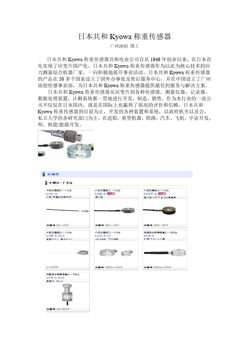
日本共和Kyowa称重传感器广州南创谭工日本共和Kyowa称重传感器共和电业公司自从1949年创业以来,在日本首先实现了应变片国产化,日本共和Kyowa称重传感器作为以此为核心技术的应力测量综合机器厂家,一向积极地展开事业活动。
日本共和Kyowa称重传感器的产品在50多个国家设立了国外办事处及售后服务中心,并在中国设立了广州南创传感事业部,为日本共和Kyowa称重传感器提供最佳的服务与解决方案。
日本共和Kyowa称重传感器从应变片到各种传感器,测量仪器,记录器,数据处理装置,计测系统都一贯地进行开发,制造,销售,作为本行业的一流公司不仅仅在日本国内,就是在国际上也赢得了很高的评价和信赖。
日本共和Kyowa称重传感器到目前为止,开发的各种装置和系统,以政府机关以及公,私立大学的各研究部门为主,在造船,重型机器,铁路,汽车,飞机,宇宙开发,坝,核能/能源开发。
日本共和Kyowa称重传感器日本共和Kyowa称重传感器称重传感器系列LMA-A-5N,LMA-A-10N,LMA-A-20N,LMA-A-50N,LMA-A-100N,LMA-A-200N,LMA-A-500 N,LMA-A-1KNLMR-S-2KNSA2,LMR-S-5KNSA2,LMR-S-10KNSA2,LMR-S-20KNSA2LCX-A-500N-ID,LCX-A-1KN-ID,LCX-A-2KN-ID,LCX-A-5KN-ID,LCX-A-10KN-ID,LCX-A-2 0KN-IDLCN-A-500N,LCN-A-1KN,LCN-A-2KN,LCN-A-5KN,LCN-A-10KN,LCN-A-20KNLCR-G-5KNSA2,LCR-G-10KNSA2,LCR-G-20KNSA2,LCR-G-30KNSA2,LCR-G-50KNSA2 LC-5TV(50KN),LC-10TV(100KN),LC-20TV(200KN)CR-5,CR-10,CR-20LCV-A-500KN,LCV-A-1MNLC-200TE,LC-500TELC-50KFH/FL,LC-100KFH/FL,LC-200KFH/FL,LC-500KFH/FL,LC-1TFH/FL,LC-2TFH/FL,LC -5TFH/FL,LC-10TFH/FL,LC-20TFH/FL日本共和Kyowa称重传感器LT-50KFH/FL,LT-100KFH/FL,LT-200KFH/FL,LT-500KFH/FL,LT-1TFH/FL,LT-2TFH/FL,LT-5T FH/FL,LT-10TFH/FL,LT-20TFH/FLLCK-A-5KN,LCK-A-10KN,LCK-A-20KN,LCK-A-50KN,LCK-A-100KN,LCK-A-200KN LCH-10TF(100KN),LCH-20TF(200KN)LC-500KJ(5KN),LC-1TJ(10KN),LC-2TJ(20KN),LC-5TJ(50KN),LC-10TJ(100KN),LC-20TJ(200 KN)LCTS-B-5KN,LCTS-B-10KN,LCTS-B-20KN,LCTS-B-30KN,LCTS-B-50KN,LCTS-B-100KN LCTA-A-500N,LCTA-A-800N,LCTA-A-1KN,LCTA-A-2KN,LCTA-A-3KNLCTB-A-5KN,LCTB-A-10KN,LCTB-A-20KN,LCTB-A-30KN,LCTB-A-50KNLCTE-A-10KN,LCTE-A-20KN,LCTE-A-30KN,LCTE-A-50KN,LCTE-A-100KNLCTD-A-100KN,LCTD-A-200KN,LCTD-A-300KN日本共和Kyowa称重传感器LCW-C-10KN(25/35/45/55/65)SA3,LCW-C-20KN(25/35/45/55/65)SA3,LCW-C-50KN(30/40/50 /60/70/80)SA3,LCW-C-100KN(30/40/50/60/70/80)SA3LCW-C-200KN(60/70/80/90/100)SA3,LCW-C-300KN(60/70/80/90/100)SA3LCW-D-1MNS,LCW-D-2MNS,LCW-D-3MNS,LCW-D-5MNSLCW-E-1MNS,LCW-E-2MNS,LCW-E-3MNS,LCW-E-5MNSLTZ-50KA,LTZ-100KA,LTZ-200KA,LTZ-500KA,LTZ-1TA,LTZ-2TA,LTZ-5TALU-50KE,LU-100KE,LU-200KE,LU-500KE,LU-1TE,LU-2TE,LU-55E,LU-10TE,LU-20TELUR-A-50NSA1,LUR-A-100NSA1,LUR-A-200NSA1,LUR-A-500NSA1,LUR-A-1KNSA1,LUR -A-2KNSA1LUX-A-500N,LUX-A-1KN,LUX-A-2KN,LUX-A-5KN,LUX-A-10KN,LUX-A-20KNLU-5KA,LU-10KA,LU-20KALUH-50KF,LUH-100KF,LUH-200KF,LUH-500KF,LUH-1TF,LUH-2TF,LUH-5TF,LUH-10TF,L UH-20TF日本共和Kyowa称重传感器LUK-A-5KN,LUK-A-10KN,LUK-A-20KN,LUK-A-50KN,LUK-A-100KN,LUK-A-200KN,LUK -A-500KN,LUK-A-1MN,LUK-A-2MN,LVS-5GA,LVS-10GA,LVS-20GA,LVS-50GA,LVS-100GA,LVS-200GA,LVS-500GA,LVS-1KA, LVS-2KALTS-50GA,LTS-100GA,LTS-200GA,LTS-500GA,LTS-1KA,LTS-2KALUB-5KB,LUB-10KB,LUB-20KB,LUB-30KB,LUB-50KB,LUB-100KB,LUB-200KB,LUB-500 KB,LUB-1TB,LUB-2TBLUB-100KC,LUB-200KC,LUB-500KC,LUB-1TC,LUB-2TC,LUB-5TCLFM-A-1KN,LFM-A-3KNLFX-A-1KN,LFX-A-3KN日本共和Kyowa称重传感器LSM-B-10NAS1,LSM-B-20NAS1,LSM-B-50NAS1,LSM-B-100NAS1,LSM-B-200NAS1,LSM-B-500NAS1LA T-1010KA-1,LA T-1010KA-2,LA T-1020KA-1,LA T-1020KA-2,LA T-1030KA-1,LA T-1030KA-2 日本共和Kyowa称重传感器LUR-B-10KNAS1,LUR-B-20KNAS1,LUR-B-30KNAS1,LUR-B-50KNAS1,LUR-B-100KNAS1, LUR-B-200KNAS1,LUR-B-300KNAS1,LUR-B-500KNAS1,LUR-B-1MNAS1,LUR-B-1.5MNAS1,LUR-B-2MNAS1,LUR-B-3MNAS1,LUR-B-5MNAS1LTA-B-20KNS,LTA-B-50KNS,LTA-B-100KNS,LTA-B-200KNS,LTA-B-300KNS,LTA-B-500KN SLTA-C-20KNS,LTA-C-50KNS,LTA-C-100KNS,LTA-C-200KNS,LTA-C-300KNS,LTA-C-500KN SLTR-S-20KNSA1,LTR-S-30KNSA1,LTR-S-50KNSA1,LTP-S-10KNS,LTP-S-20KNS,LTP-S-50KNS,LTP-S-100KNS,LTP-S-200KNS,LTP-S-500KNS, 日本共和Kyowa称重传感器LCD-A-30KNS1, LCD-A-30KNS2, LCD-A-30KNS3, LCD-A-50KNS4, LCD-A-50KNS5, LCD-A-50KNS6, LCD-A-50KNS7, LCD-A-100KNS8,LCD-A-100KNS9LCD-B-5KNS,LCD-B-10KNS,LCD-B-20KNSLCD-C-30KNS,LCD-C-50KNS,LCD-C-70KNS,LCD-C-100KNSLCD-D-500KNS,LCD-D-1MNS,LCD-D-1500KNS,LCD-D-2MNS,LCD-D-3MNS,LCD-D-3500 KNS,LCD-D-5MNSLCR-B-5KNS7,LCR-B-10KNS7,LCR-B-20KNS7,LCR-B-30KNS7,LCR-B-50KNS7,LCR-B-100 KNS7,LCR-B-200KNS7。
日本费加罗FIGARO可燃气体传感器 TGS813

Technical Information for Combustible Gas SensorsFigaro TGS 8-series sensors are a type of sintered bulk metal oxide semiconductor wh ich offer low cost, long life, and good sensitivity to target gases while utilizing a simple electrical circuit. Th e TGS813 displays h igh selectivity and sensitivity to LP Gas and methane.PageSpecificationsFeatures..........................................................................2 Applications...................................................................2 Structure..........................................................................2 Basic measuring circuit....................................................2 Circuit & operating conditions.........................................3 Specifications..............................................................................3 Dimensions...............................................................................3Basic Sensitivity Characteristics Sensitivity to various gases................................................4 Temperature and humidity dependency............................5 Heater voltage dependency..........................................................6 Gas response....................................................................................6 Initial action........................................................................7 Long term characteristics.............................................................7Cautions . (8)See also Technical Brochure ‘Technical Information on Usage of TGSSensors for Toxic and Explosive Gas Leak Detectors’.IMPORTANT NOTE: OPERATING CONDITIONS IN WHICH FIGARO SENSORS ARE USED WILL VARY WITH EACH CUSTOMER’S SPECIFIC APPLICATIONS. FIGARO STRONGLY RECOMMENDS CONSULTING OUR TECHNICAL STAFF BEFORE DEPLOYING FIGARO SENSORS IN YOUR APPLICATION AND, IN PARTICULAR, WH EN CUSTOMER’S TARGET GASES ARE NOT LISTED H EREIN. FIGARO CANNOT ASSUME ANY RESPONSIBILITY FOR ANY USE OF ITS SENSORS IN A PRODUCT OR APPLICATION FOR WHICH SENSOR HAS NOT BEEN SPECIFICALLY TESTED BY FIGARO.a n I S O 9001 c o m p a n y1. Specifications 1-1 Features * General purpose sensor for a wide range of combustible gases* High sensitivity to LP gas and methane * Low cost * Long life* Uses simple electrical circuit1-2 Applications* Domestic gas leak detectors and alarms * Recreational vehicle gas leak detectors * Portable gas detectors1-3 StructureFigure 1 shows the structure of TGS813. This sensor is a sintered bulk semiconductor composed mainly of tin dioxide (SnO 2). The semiconductor material and electrodes are formed on an alumina ceramic tube. A heater coil, made of 60 micron diameter wire, is located inside the ceramic tube. Lead wires from the sensor electrodes are a gold alloy of 80 microns in diameter. Heater and lead wires are spotwelded to the sensor pins which have been arranged to fit a 7-pin miniature tube socket.The sensor base and cover are made of Nylon 66, conforming to UL 94H B (Authorized Material Standard). The deformation temperature for this material is in excess of 240˚C. The upper and lower openings in the sensor case are covered with a flameproof double layer of 100 mesh stainless steel gauze (SUS316). Independent tests confirm that this mesh will prevent a spark produced inside the flameproof cover from igniting an explosive 2:1 mixture of hydrogen/oxygen.1-4 Basic measuring circuitFigure 2 shows the basic measuring circuit for use with TGS813. Circuit voltage (Vc) is applied across the sensor element which has a resistance between the sensor’s two electrodes and the load resistor (R L ) connected in series. The sensor signal (V RL ) is measured indirectly as a change in voltage across the R L . The Rs is obtained from the formula shown at the right.Fig. 1 - Sensor structureFig. 2 - Basic measuring circuitVc- V RLV RLRs = x R LFormula to determine RsSensor elementFig. 3 - Sensor dimensions1-5 Circuit & operating conditionsThe ratings shown below should be maintained at all times to insure stable sensor performance:1-6 Specifications NOTE 1Mechanical Strength:The sensor shall have no abnormal findings in its structure and shall satisfy the above electrical specifications after the following performance tests:Withdrawal Force - Vibration - Shock -withstand force > 5kg in eachdirectionfrequency-1000c/min., totalamplitude-4mm, duration-one hour, direction-verticalacceleration-100G, repeated 5timesNOTE 1: Sensitivity characteristics are obtained under the following standard test conditions:(Standard test conditions)Temperature and humidity: 20 ± 2˚C, 65 ± 5% RH Circuit conditions:Vc = 10.0±0.1V AC/DC V H = 5.0±0.05V AC/DC R L = 4.0kΩ ± 1%Preheating period: 7 days or more under standard circuit conditions17ø±0.516.5±0.56.5±0.59.5ø1ø±0.0545˚45˚132645u/m:mm1-7 DimensionsTop viewSide viewBottom view2. Basic Sensitivity Characteristics 2-1 Sensitivity to various gasesFigure 4 shows the relative sensitivity of TGS813 to various gases. The Y-axis shows the ratio of the sensor resistance in various gases (Rs) to the sensor resistance in 1000ppm of methane (Ro).Using the basic measuring circuit illustrated in Figure 2, these sensitivity characteristics provide the sensor output voltage (V RL ) change as shown in Figure 5.NOTE :All sensor characteristics in this technical brochure represent typical sensor characteristics. Since the Rs or output voltage curve varies from sensor to sensor, calibration is required for each sensor (for additional information on calibration, please refer to the Technical Advisory ‘Technical Information on Usage of TGS Sensors for Toxic and Explosive Gas Leak Detectors’).12-2 Temperature and humidity dependencyFigure 6 shows the temperature and humidity dependency of TGS813. The Y-axis shows the ratio of sensor resistance in 1000ppm of methane under various atmospheric conditions (Rs) to the sensor resistance in 1000ppm of methane at 20˚C/65%RH (Ro).under various ambient conditionsTable 1 - Temperature and humidity dependency(typical values of Rs/Ro for Fig. 6)Table 1 shows a chart of values of the sensor’s resistance ratio (Rs/Ro) under the same conditions as those used to generate Figure 6.Figure 7 shows the sensitivity curve for TGS813 to methane under several ambient conditions. While temperature may have a large influence on absolute Rs values, this chart illustrates the fact that effect on the slope of sensor resistance ratio (Rs/Ro) is not significant. As a result, the effects of temperature on the sensor can easily be compensated.For economical circuit design, a thermistor can be incorporated to compensate for temperature (for additional information on temperature compensation in circuit designs, please refer to the Technical Advisory ‘Technical Information on Usage of TGS Sensors for Toxic and Explosive Gas Leak Detectors’).1010Rs (kΩ)102-6 Initial actionclean air.process is called “Initial Action”.circuit be incorporated into the detector’s design (TGS Sensors for Toxic and Explosive Gas Leak Detectors’). This is especially recommended for intermittent-operating devices such as portable gas detectors.2-7 Long-term characteristicsFigure 13 shows long-term stability of TGS813 as measured for more than 8 years. The sensor is first energized in normal air. Measurement for confirming sensor characteristics is conducted under ambient air conditions rather than in a temperature/humidity controlled environment. The cyclic change in sensitivity corresponds to the seasonal changes of temperature/humidity in Japan (peak T/H conditions occur in July, as corresponds with the sensitivity peaks in this chart ). The Y-axis represents the ratio of sensor resistance in 1000ppm of methane on the date tested (Rs) to sensor resistance in 1000ppm of methane at the beginning of the test period (Ro).As this chart illustrates, TGS813 shows stable characteristics over a very long period of time.Fig. 12 - Long term stability(Ro = Rs on day 1)3 Cautions3-1 Situations which must be avoided1) Exposure to silicone vaporsIf silicone vapors adsorb onto the sensor’s surface, the sensing material will be coated, irreversibly inhibiting sensitivity. Avoid exposure where silicone adhesives, hair grooming materials, or silicone rubber/putty may be present.2) Highly corrosive environmentHigh density exposure to corrosive materials such as H2S, SOx, Cl2, HCl, etc. for extended periods may cause corrosion or breakage of the lead wires or heater material.3) Contamination by alkaline metalsSensor drift may occur when the sensor is contam-inated by alkaline metals, especially salt water spray.4) Contact with waterSensor drift may occur due to soaking or splashing the sensor with water.5) FreezingIf water freezes on the sensing surface, the sensing material would crack, altering characteristics.6) Application of excessive voltageIf higher than specified voltage is applied to the sensor or the heater, lead wires and/or the heater may be damaged or sensor characteristics may drift, even if no physical damage or breakage occurs.7) Application of voltage on lead wiresOn six-pin type sensors, if a voltage is applied on the lead wires between pins 1 and 3 and/or pins 4 and 6, this would cause breakage of the lead wires.8) Operation in zero/low oxygen environment TGS sensors require the presence of around 21% (ambient) oxygen in their operating environment in order to function properly and to exhibit characteristics described in Figaro’s product literature. TGS sensors cannot properly operate in a zero or low oxygen content atmosphere.3-2 Situations to be avoided whenever possible1) Water condensationLight condensation under conditions of indoor usage should not pose a problem for sensor performance.H owever, if water condenses on the sensor’s surface and remains for an extended period, sensor characteristics may drift.2) Usage in high density of gasSensor performance may be affected if exposed to a high density of gas for a long period of time, regardless of the powering condition.3) Storage for extended periodsWhen stored without powering for a long period, the sensor may show a reversible drift in resistance according to the environment in which it was stored. The sensor should be stored in a sealed bag containing clean air; do not use silica gel. Note that as unpowered storage becomes longer, a longer preheating period is required to stabilize the sensor before usage. 4) Long term exposure in adverse environment Regardless of powering condition, if the sensor is exposed in extreme conditions such as very high humidity, extreme temperatures, or high contamination levels for a long period of time, sensor performance will be adversely affected.5) VibrationExcessive vibration may cause the sensor or lead wires to resonate and break. Usage of compressed air drivers/ultrasonic welders on assembly lines may generate such vibration, so please check this matter.6) ShockBreakage of lead wires may occur if the sensor is subjected to a strong shock.7) SolderingIdeally, sensors should be soldered manually. For soldering conditions of 8-series gas sensors, refer to Technical Advisory for Soldering 8-type Gas Sensors. 8) PolarityIf the polarity of Vc is reversed during powering, sensor characteristics may temporarily become unstable.15 24 36Figaro USA Inc. and the manufacturer, Figaro Engineering Inc. (together referred to as Figaro) reserve the right to make changes without notice to any products herein to improve reliability, functioning or design. Information contained in this document is believed to be reliable. H owever, Figaro does not assume any liability arising out of the application or use of any product or circuit described herein; neither does it convey any license under its patent rights, nor the rights of others.Figaro’s products are not authorized for use as critical components in life support applications wherein a failure or malfunction of the products may result in injury or threat to life.。
光电传感器和烟雾传感器用于烟气浊度检测

光电传感器和烟雾传感器用于烟气浊度检测众所周知,钢铁、有色金属冶炼、火力发电、水泥和石化企业的生产过程,汽车和飞机的尾气,以及垃圾焚烧、供暖锅炉和家用炉灶都会排放大量的烟尘。
烟尘里面的物质很复杂,例如,锅炉在燃烧过程中会产生大量烟尘,包括二氧化硫、氮氧化物和其他大气污染物。
这些污染物被排放到大气中,形成酸雨等,严重破坏生态平衡,给人们的生活带来极大的不便。
全世界每年约有1亿吨烟尘排放到空气中,其中不乏有毒烟尘。
如果不及时处理,它不仅会对我们的生存环境造成破坏,还会影响人类健康甚至生命。
由于各种有害物质附着在尘粒表面,一旦进入人体,就会引起各种呼吸道疾病。
工采网下面简单说一下烟尘对人体的危害:燃煤和工业生产中排放的烟尘固体颗粒对人体的危害要比其他烟尘危害更大。
它的主要成分是二氧化硅、氧化铝、氧化铁、氧化钙和未燃烧的碳颗粒。
烟尘对人体的危害与烟尘浊度及烟尘颗粒物大小有关:大于5微米的烟尘颗粒会被鼻毛和气道粘液堵塞,小于0.5微米的颗粒物通常会粘附在上呼吸道表面,并随痰排出。
而直径为0.5-5微米的颗粒物对人体危害最大,它不仅沉积在肺部,还直接进入血液到达人体的各个部位。
因此,减少烟尘排放和降低烟气浓度是中国环境保护的重要组成部分。
监测烟尘浊度是减少烟尘排放的有效措施。
工采网了解到在烟尘浊度检测上可以使用光电传感器和烟雾传感器来进行监测。
用光电传感器检测烟尘浊度的原理:烟气中烟尘的浊度是通过烟气传播过程中光线的变化来检测的。
如果烟气浊度增加,光源发出的光被烟尘颗粒吸收和折射,到达光电传感器的光减少,因此光电探测器输出信号的强度可以反映烟气浊度的变化。
工采网推荐用日本NEMOTO 离子式烟雾传感器- NIS-02C来检测烟尘浊度,和其他烟雾传感器同样在内部使用极其微量的放射性物质241Am。
在烟雾报警器内部,作为废物处理没有任何规定。
此产品尺寸、形状、烟雾敏感度和NIS-09C 完全一样,可随意互换。
日本根本特殊化学株式会社可燃气体传感器NAP-55A
USER'S MANUALHOT-WIRE TYPE GAS SENSOR NAP-55A & 50A(For All Combustible Gases, Low Power Consumption) CONTENTS1. Features & applications2. Specifications3. Gas sensitivity characteristics4. Response characteristics5. Voltage dependency characteristics6. Temperature characteristics7. Humidity characteristics8. Evaluation on sensor9. Drawings深圳市深国安电子科技有限公司地址:广东省深圳市龙华新区牛栏前大厦C507 蒋小姐:134 2876 2631 电话:86 755-852589001. GeneralNemoto's NAP-55A & 50A are miniature-sized hot-wire type gas sensors for every combustiblegases. These new sensors are smaller than our NAP-2A sensor and consume much less power.(Approx. half a wattage of NAP-2A). These sensors respond 30% quicker than NAP-2A.NAP-55A is sensitive to all combustible gases, while NAP-50A has lower sensitivity only toalcohol. NAP-55A would be suitable for general applications, and NAP-50A would be the bestfor residential gas detectors which should not be affected by noise gases other than fuel gases.1) Features* Excellent stability.* Remarkable reproducibility and accuracy.* Linear output signal for natural (city) gas concentration.* Superior response characteristics.* Miniature size for flexibility in the design of detectors.2) Applications* Gas densitometers* City gas leakage detectors2. Specifications1) Voltage supplied to sensor bridge ; D.C. ; 2.50 +/- 0.25 VA.C. ; 2.50 +/- 0.25 V(r.m.s. 50 ~ 60 Hz)2) Current (when 2.50 V is supplied) ; D.C. ; 160 ~ 180 mAA.C. ; 160 ~ 180 mA(r.m.s. 50 ~ 60 Hz)3) Ambient temperature &humidity during operation ; Temperature : -10o C ~ +50o CHumidity : Less than 95% RH4) Ambient temperature &humidity during storage ; Temperature : -20o C ~ +60o CHumidity : Less than 95% RH5) Output voltage in air ; Va : -35 ~ +35 mV6) Gas sensitivity ; ∆S : 11 ~ 16 mV (Methane 3,000 ppm)7) Reproduceability in a day ; Va : Within +/- 0.5 mV∆S : Within +/- 0.5 mV深圳市深国安电子科技有限公司3. Gas sensitivity_of N AP-55A3-1 Gas concentration characteristics3-2 Standard deviation of gas sensitivity to CH 4 (Individual difference)10203000.10.20.30.40.5Gas Concentration (vol%)iso-C 4H 10H 2C 2H 5OH CH 401020304000.20.40.60.8CH 4 Gas Concentration (ppm)+σ-σaverage深圳市深国安电子科技有限公司4. Response characteristics(Measurement example ; Comparison to NAP-2A)The times are ones to be required for 90% response. 深圳市深国安电子科技有限公司5. Voltage dependency characteristicsVoltage dependency on NAP-55A gas sensitivityVoltage dependency on output in air2.25 2.50 2.752-2V o u t i n A i r (m V )Supply Voltage (V)2.252.50 2.75Supply Voltage (V)1020∆V o u t i n C H (m V )4深圳市深国安电子科技有限公司Voltage dependency on theoretical alarm concentration2.752.502.25Supply Voltage (V)20002500300035004000T h e o r i t i c a l A l a r m G a s C o n c e n t r a t i o n o f C H (p p m )4深圳市深国安电子科技有限公司6. Temperature characteristics7. Humidity characteristics3030404050502020101000-10-10-22Temperature (C)oTemperature (C)oV o u t i n A i r (m V)∆V o u t i n C H 3000p p m (m V )42015105303060609090Relative Humidity (%)Relative Humidity (%)-22V o u t i n A i r (m V )∆V o u t i n C H 3000p p m (m V )42015105深圳市深国安电子科技有限公司8. Evaluation of sensors(1) Testing equipmentThe following is and outline of a test system.Remarks:1) Test chamber ;* Metal or glass which does not generate or absorb gases is desirable as test chamber material.* The volume of the chamber should be larger than 1 liter / sensor.2) Gas densitometer ;* An infrared gas densitometer is recommended for measuring gas concentration.3) Air agitation ;*The air inside the chamber should be agitated, but not so as to directly blow on the sensor.Air flow should be less than 0.5m/sec.深圳市深国安电子科技有限公司地址:广东省深圳市龙华新区牛栏前大厦C507 4) Power supply ;*Sensors can be operated using either D.C. or A.C., but for optimal measurement accuracy, use of a D.C. voltage stabilizer is recommended.5) Voltmeter ;* A voltmeter with greater than 100K ohm impedance is sufficient for measuring sensor bridge out put voltage.6) Ventilation ;*Before proceeding with a subsequent test, the air inside the test chamber should be ventilated using a ventilator which has a capacity of more than 10 times the volume of the chamber perminute.7) Placement of sensors in a test chamber ;*Sensors should be placed in a chamber in a same attitude. (Normally horizontal).Changing the attitude creates different thermal convection, and may causeinaccuratemeasurement results.(2)Adjustment of gas concentrationGas concentration in a test chamber is usually adjusted by a volumetric method injecting iso-butane gas using a syringe, or by monitoring with an infra-red gas densitometer.Gas concentration adjustment by a volume method can be calculated according to thefollowing formula.V;Volume of gas to be injectedV1 ;Inside volume of a chamber (ml)C ;Gas concentration to be adjustedTR;Room temperature (o C)T; Temperature inside a chamber (o C)深圳市深国安电子科技有限公司地址:广东省深圳市龙华新区牛栏前大厦C507 (3) Measurement1) Preparatory aging;* Before measurement, sensors should be supplied with the specified voltage at least for more than 1 hour.2) Measurement;* After confirming that the output voltage level has stabilized, the output value in air (Va) is measured.* A test gas is injected into the test chamber and wait for an even dispersion of the gas inside the chamber. (Usually 1 min. or more)* Output voltage in gas (Vg) is measured.* Thoroughly ventilate the test chamber with a fresh air from outside.(4) Other remarks* Sensors should not be dropped or subjected to strong shocks.* Refrain from use in an atmosphere that may contain poisonous or corrosive gases.* Do not soak sensors in water.深圳市深国安电子科技有限公司地址:广东省深圳市龙华新区牛栏前大厦C507 蒋小姐:134 2876 2631 电话:86 755-85258900网址:www.singoan.com www.singoan.com.cn www.shenguoan.com9. Drawings深圳市深国安电子科技有限公司地址:广东省深圳市龙华新区牛栏前大厦C507 SUPPLEMENT TO USER'S MANUAL FOR NAP-55A CONTENTS10. Resistance to silicone contamination11. Drop (Impact) resistance12. Wind effects13. Life expectance14. Long term stability深圳市深国安电子科技有限公司地址:广东省深圳市龙华新区牛栏前大厦C507 10. Silicone contamination resistance test resultsSilicone material Hexamethyldisilixane (HMDS) (CH3)3SiOSi(CH3)3 10ppm : Silicone oilTime of exposure 1 hourTest equipment 14 liter desiccator, Room temperature and humidityTest gas CH4 3,000 ppmBefore contamination (mV) After contamination (mV) Test samplesOutput in air in 3,000ppm of CH4Output in air in 3,000ppm of CH41 Contamination- 14.3 12.5 - 14.2 9.9 without power supply2 " - 13.3 13.0 - 13.3 11.03 " - 0.8 12.9 - 1.0 11.14 " + 0.2 12.4 + 0.3 10.55 " + 10.4 12.5 + 10.2 9.56 Contamination with- 12.2 12.2 - 12.1 9.2 power supply7 " - 19.9 13.1 - 19.8 8.98 " - 15.2 12.8 - 15.0 8.49 " + 12.2 12.7 + 12.1 8.610 " + 23.7 12.8 + 23.8 8.8深圳市深国安电子科技有限公司11. Drop (Impact) test resultsTest conditions Dropped three times (Direction unspecified) on to a wooden plate (30mmthick) from a height of 50cm.Test samples Residential gas leakage detectors on the market (300g with a power code)Test method Fixed resistors for bridge circuit were put outside (Inside circuit was notused), and power was supplied, then fluctuations in output voltage wereobserved using a pen-recorder.Sample No. Trial 1 Trial 2 Trial 3A + 1.0 + 1.3 + 1.0B - 1.5 - 0.8 + 0.5C - 1.1 - 0.5 - 1.2D + 1.4 + 0.5 - 0.1E - 0.3 - 0.4 - 0.8F + 1.0 + 0.5 + 1.1G - 1.6 - 1.4 - 1.2H + 1.5 + 1.0 + 0.8I + 0.5 + 0.1 - 0.4J - 1.3 - 1.0 - 0.7* Fluctuation compared to initial output (mV)深圳市深国安电子科技有限公司地址:广东省深圳市龙华新区牛栏前大厦C507 12. Wind effects test resultsBecause of its housing structure, NAP-55A's output voltage is little affected by wind. Below are the test results due to wind effects for NAP-55A and NAP-2A.No. Wind direction Description1 From sensor side Wind hits the sensing element2 From compensator side Wind hits the compensating element3 Parallel to sensor and compensator Wind hits both elements from the side4 From top Wind hits both elements through the mesh netFluctuation of output in air (mV) Wind direction and velocityNAP-55A NAP-2A From sensor side, 1.5m/sec. Approx. - 1 Approx. - 4From sensor side, 3.0m/sec. Approx. - 1 Approx. - 24From compensator side, 3.0m/sec. Approx. + 1 Approx. + 21Parallel to sensor and compensator, 3.0m/sec. Approx. +/-1 Approx. +/-2From top, 3.0m/sec. Approx. +/-1 Approx. +/-1 * Remarks: Output voltages fluctuate during measurement.深圳市深国安电子科技有限公司地址:广东省深圳市龙华新区牛栏前大厦C507 13. Life expectanceTest methods and results(1) Overloaded voltage testSensors were continuously energized with 120%, 130%, and 140% of the rated supplyvoltage and stored under room temperature and humidity, then periodically outputvoltages in air were measured, giving the rated voltage. Figure 8 indicates that thelife expectancy of NAP-55A would be 8.4 years. (x axis is the time required until theoutput in air deviates by 5 mV, right y axis is supply voltage, and left y axis isreciprocal numbers of the filament temperature). It is assumed that a sensor is deadwhen its output deviates by 5 mV.(2) Accelerating test under high temperature and humiditySensors were energized with the rated voltage. C3H7OH solution was constantlysupplied to maintain a sensor output at 150 mV with at least 95% relative humidity,and temperature of 74, 87, and 97 degrees Celsius.Figure 9 indicates that the life expectancy of NAP-55A would be 7.3 years. (x axis is thetime required until the sensitivity to CH4 at room temperature and humidity decreasesby 50% of the initial value, and the right y axis is the storage temperature). It isassumed that a sensor is dead when its gas sensitivity to methane decreases by 50% ofthe initial gas sensitivity.(3) Accelerating test using hydrogen gasSensors were energized with 110% of the rated voltage and stored in 1,000~200ppm ofH2 gas at 50o C and 30~40%RH. Output voltages were then examined. No effectsdue to the hydrogen gas were observed. According to a Japanese gas detectormanufacturer who proposed this test, the test conditions would be 42.4 times harsherthan normal atmospheric conditions.深圳市深国安电子科技有限公司地址:广东省深圳市龙华新区牛栏前大厦C507 蒋小姐:134 2876 2631 电话:86 755-85258900Fig. 8 Life expectancy test on NAP-55A with oversupplied voltage(Life = Deviation of 5 mV form zero point)Test conditions ;* At room temperature and humidity* Supplied with 140%, 130%, and 120% of rated voltageFig. 9 Life expectancy test for NAP-55A under high temperature and humidity(Life = 50% of initial gas sensitivity is lost) Test conditions : Temperature ; 97o C, 87o C, and 74o C, Humidity ; _ 95% RH Sensor output was maintained at 150 mV by adjusting CH 4 gas concentration, and 1% C3H7OH solution was supplied to maintain constant test conditions.2.83.03.23.4100100010000Time (hrs.)20304050607080901001.101.201.301.401.50101001000Time (days)2.502.753.003.253.50深圳市深国安电子科技有限公司Fig. 10 Long term energizing test in H 2 gas-2246050100Time (days)00.51.0050100Time (days)00.20.450100Time (days)深圳市深国安电子科技有限公司地址:广东省深圳市龙华新区牛栏前大厦C507 14. Long term stabilitym a x .a v e r a g e o f 25 s a m p l e sm i n .F i g . 11 L o n g t e r m s t a v i l i t y t e s t s o n N A P -55AT i m e (M o n t h e s )T h e o r e r i c a l a l a r m g a s c o n c e n t r a t i o n (p p m )Z e r o p o i n t d r i f t i n A i r (m V )G a s s e n s i t i v i t y t o 3% o f C H 4深圳市深国安电子科技有限公司。
- 1、下载文档前请自行甄别文档内容的完整性,平台不提供额外的编辑、内容补充、找答案等附加服务。
- 2、"仅部分预览"的文档,不可在线预览部分如存在完整性等问题,可反馈申请退款(可完整预览的文档不适用该条件!)。
- 3、如文档侵犯您的权益,请联系客服反馈,我们会尽快为您处理(人工客服工作时间:9:00-18:30)。
Technical Information(C a t a l y t i c T y p e G a s S e n s o r)Model NC-70S(Single Header Type)For Industrial Application深圳市深国安电子科技有限公司地址:广东省深圳市龙华新区牛栏前大厦C507 蒋小姐:134 2876 2631 电话:86 755-85258900网址:www.singoan.com www.singoan.com.cn www.shenguoan.com1.GeneralCatalytic type gas sensor NC series were developed for industrial applications, and NC-70S is a single header type gas sensor for general combustible gases. Supply voltage and current are compatible with other sensors, however the shape is quite different from others. On the other hand, the reliability, repeatability, stability and responsibility are quite superior to others, additionally the durability in strict circumstance are quite excellent. Features and typical applications are as follows.2.Features and applications1)Features・Good stability・Excellent repeatability and detection accuracy・Good linearity against gas concentration・Quick response・Down sizing for design flexibility of wearable or handheld gas alarm or detector2)Applications・Portable, wearable of handheld type gas alarm or detector for general combustible gases・Gas densitometer3.Ratings1)Supply voltage to sensor AC 3.0 +/- 0.1V(50-60Hz)DC 3.0 +/- 0.1V2)Current (when 3.0V is supplied) AC 70 +/- 10mA(50-60Hz)DC 70 +/- 10mA3)Ambient temperature and humidity in operationTemperature -20 - +60 degree CHumidity Less than 95%RH(without dew condensation)4)Ambient temperature and humidity in storageTemperature -30 - +70 degree CHumidity Less than 99%RH(without dew condensation)5)Detection range 0 – around 60%LELLower accuracy over 60%LEL(Except acetylene)4.Specification1)Zero offset value in air 0 +/- 20mV(compensated by trimming resistor*)2)Minimum sensitivity 50mV/1% of methane3)Response time Less than 20 sec. at T904)Linearity Effectively linear to 60%LEL5)Detection accuracy +/- 1%LEL6)Span drift Less than 10%/3 month深圳市深国安电子科技有限公司地址:广东省深圳市龙华新区牛栏前大厦C507 蒋小姐:134 2876 2631 电话:86 755-852589007)Zero offset drift Less than 10%/3 month8)Warranty period 12 monthsz Resistance value of trimming resistor is indicated one by one.5.Appearance and dimensionFig. 1 : Appearance and dimensionsRemarks)Since the enclosure of sensor is made of plastic resin, it does not have high temperature resistance.6.Measuring circuit diagram深圳市深国安电子科技有限公司地址:广东省深圳市龙华新区牛栏前大厦C507 蒋小姐:134 2876 2631 电话:86 755-85258900Input(+)Input(G N D)Fig. 2 : Recommended circuit diagram(R1, 2 : 200ohm, VR1 : 3Kohm)Remarks)Fixed resistor for trimming is to be attached parallel with compensator or detector according to the indication of each sensor.7.Gas sensitivity characteristicsFig. 3 : Gas sensitivity characteristics8.Temperature dependence at 60%RH深圳市深国安电子科技有限公司地址:广东省深圳市龙华新区牛栏前大厦C507 Fig. 4 : Temperature dependence of zero offsetFig. 5 : Temperature dependence of relative sensitivity to methane9.Humidity dependenceFig. 6 : Humidity dependence of zero offset(at 25 degree C)深圳市深国安电子科技有限公司地址:广东省深圳市龙华新区牛栏前大厦C507 蒋小姐:134 2876 2631 电话:86 755-85258900Fig.7 : Humidity dependence of relative sensitivity to methane10.Long term stabilityFig. 8 : Long term stability of relative sensitivity to methane11.Sensitivity and zero offset distributionFig. 9 : Sensitivity distribution深圳市深国安电子科技有限公司Fig. 10 : Zero offset distribution with compensation by trimming resistor12.Relative sensitivity(In case that sensitivity to methane is 100.)Gas/Vapor Chemical formula LEL (%) Relative sensitivityStd. Methane CH4 5.0 1001 Acetone (CH3)2CO 2.6 952 Ethanol C2H5OH 3.3 1003 Ethyl acetate CH3COOC2H5 2.2 804 Ethylene C2H4 2.7 1105 Hydrogen H2 4.0 1406 Iso-propanol CH3-C2H4OH 2.2 907 Methanol CH3OH 6.7 1508 Methyl ethyl ketone CH3-CO-C2H5 1.9 709 N-butane C4H10 1.8 7510 N-heptane C7H16 1.05 6511 N-hexane C6H14 1.2 7012 N-pentane C5H12 1.4 7013 Propane C3H8 2.1 8014 N-octane C8H18 0.95 6015 Toluene C6H5CH3 1.2 8016 Ammonia NH3 15.0 15017 Carbon monoxide CO 12.5 16018 Unleaded petrol 1.2 75Remarks)If other data are required, please contact us since sensitivity of many combustible gases except bad smell, dangerous, poisonous and high boiling temperature materials over 120 degree C are available for investigations.深圳市深国安电子科技有限公司地址:广东省深圳市龙华新区牛栏前大厦C507 13. Durability1)Exposure in hydrogen sulfideTest conditionsSensors were exposed in 50%LEL of methane and 25ppm of hydrogen sulfide for 1hr. at normaltemperature and humidity.No.Before test (mV) After test (mV)Zero offset Relative sensitivity to CH4 Zero offset Relative sensitivity toCH41 -10.5 100 -7.2 1002 13.4 100 16.8 963 11.1 100 13.9 972)Exposure in HMDSTest conditionsSensors were exposed in 50%LEL of methane and 10ppm of HMDS for 1hr. at normal temperatureand humidity.No.Before test (mV) After test (mV)Zero offset Relative sensitivity to CH4 Zero offset Relative sensitivity to CH41 14.4 100 16.1 662 7.1 100 8.8 583 2.5 100 2.8 723)Drop testTest conditionsSensors were dropped from the height of 30cm onto the wood board of 3cm thickness with free fallby 3 times.No.Before test (mV) After test (mV)Zero offset Relative sensitivity to CH4 Zero offset Relative sensitivity to CH41 4.1 100 5.7 1042-7.9 100 -8.2 101-4.4 100 -4.9 102 34)Vibration testTest conditionsVibration which is 10Hz with the 4mm of amplitude for 20min. to 3 directions of X, Y and Z wasadded to sensors at normal temperature and humidity.No.Before test (mV) After test (mV)Zero offset Relative sensitivity to CH4 Zero offset Relative sensitivity to CH41 -17.6 100 -17.1 1002 11.0 100 10.4 1023 -7.6 100 -7.1 102深圳市深国安电子科技有限公司地址:广东省深圳市龙华新区牛栏前大厦C507 蒋小姐:134 2876 2631 电话:86 755-8525890012. Evaluation method1.Test equipmentOutline of test equipment is as follows.Remarks on equipments)A)Test chamber・Material of test chamber is to be inactive like metal, glass or acrylic resin which does not exhale and adsorb gases.・V olume of test chamber is to be more than 1 litter per 1pc. of sensor.B)Circumstance・Clean circumstance is recommended as evaluation area. Dirty circumstance which contains combustible gases like organic solvent vapor is to be avoided.C)Gas densitometer・Laser gas densitometer is recommended, but volume method is available simply.D)Agitation in test chamber・Air agitation in test chamber is to be conducted carefully in order not to flow air to sensor directly. Air velocity to sensor is to be less than 0.5m/sec.E)Power supply・Both of AC power and DC power are available for sensor, however DC power supply is recommended for accurate evaluation.F)Digital volt meter・Since the impedance of sensor is fairly low, general digital volt meter having over 100kohm as input impedance is sufficiently available.G)Ventilation・Ventilator with ventilation capacity of over 10 times/min. of the volume of test chamber is recommended for the convenient evaluation.深圳市深国安电子科技有限公司H)Installation position of sensor in test chamber・When the sensor is installed in test chamber, it should be careful that each sensor is to be in constant position because output signal changes in case that position of sensor changes. If the rough evaluation is carried out, such careful treatment is not necessary.2.Adjustment of gas concentrationAdjustment of gas concentration is to be conducted by volume method or by using laser gas densitometer. In case of volume method, gas volume to be injected into a chamber is obtained from the calculation formula below described.V m Vi C Tr Tc()l=++−・・102732736V: Gas volume to be injectedVi: V olume of test chamber()m lTc: Temperature in test chamber(℃)Tr: Room temperature(℃)C: Target gas concentration (ppm)3.Evaluation methodA.Preliminary aging・Before evaluation of sensor, preliminary aging at rated voltage for over 1 hr. is recommended for accurate evaluation.B.Measurement・At first, output voltage in clean air is measured. It should be confirmed that output voltage has to be stable without fluctuation.・Output voltage is measured around 1min. later after the designated volume of gas is injected intoa test chamber.・Inside of test chamber should be substituted of clean air by ventilator.4.Notice on handling・Sensor is to be gently handled without adding shock or dropping.・Handling in a location which corrosive gases or poisonous gases exist is to be avoided.・Sensor does not have to be dipped in water.・Sensor does not have to be disassembled.・Do not cut pins in any case.・It has explosion proof structure, however it is recommended to be assembled in an approved body.深圳市深国安电子科技有限公司地址:广东省深圳市龙华新区牛栏前大厦C507 蒋小姐:134 2876 2631 电话:86 755-85258900。