rainingLimit料位开关中文版
料位开关的作用

料位开关的作用
料位开关是一种用于监测或控制储料设备中物料水平的开关装置。
它的基本功能是通过检测物料水平的上升或下降来触发开关信号,以此实现对储料设备的监控和管理。
料位开关还能预警卡料、空料等异常情况,有助于预防设备故障和安全事故的发生。
在实际应用中,料位开关可以根据不同的需求选择合适的类型,如阻旋料位开关、音叉料位开关、电容式料位开关、射频导纳料位开关等。
这些开关可以用于高、低料位或中间料位的测量,并且它们通常具有良好的密封性、过载能力以及轻便易装的特性。
料位开关不仅适用于流动性良好的物料,而且在化工、塑料、水泥、医药、饲料、食品等行业有着广泛的应用,尤其是在保障生产安全和提高作业效率方面发挥着重要作用。
特别地,防爆阻旋料位开关在化工生产中扮演着至关重要的角色。
它能在高温、高压、易燃易爆的环境中正常工作,并通过监测物料位置及时发出报警信号,帮助工作人员采取措施避免设备故障或安全事故。
此外,料位开关还有助于防止物料过载和欠载,提高生产效率,并在一定程度上确保安全生产。
APL-9系列钢质限位开关安装与维护手册说明书
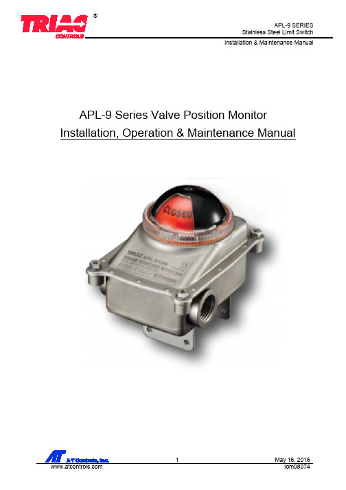
APL-9 Series Valve Position Monitor Installation, Operation & Maintenance ManualContents1.General (3)2.Standard specification (3)3.Standard Features (4)4.Installation (5)4.1.Mounting bracket (5)4.2.Mounting limit switch box (5)4.3.Cam setting (6)4.4.Wiring (6)5.Maintenance (8)6.Inspection (8)7.Storage (8)8.Trouble shooting (8)9.Tools (9)10.Installation and Maintenance Tips (9)1. GeneralTRIAC Controls APL-9 series limit switch box is designed to provide accurate and reliable valve position signaling and indicating of most valves or actuators manufactured. The press-formed, all stainless-steel housing provides a lightweight and compact design with high corrosion resistance.APL-9 limit switch boxes consist of a visual position indicator, quick-set cam assembly, terminal strip, switch assembly and integral mounting bracket. Quick-set cam allows for a quick and simple hand operation in the setting of switches.2. Standard specificationModel APL-9** *Electrical Ratings Type 4x / 6, IP66 / 67Enclosure Material 304 stainless steelAmbient Temperature -20°C ≤ Ta ≤ +80°CConduit Entries Two NPT 1/2”Travel Angle 90 degree +/- 10%Position Indicator Open: GreenClose: RedLanguage: EnglishMechanical Switch SPDT (10, 12): 16A 1/2HP 125/250Vac, 0.6A 125Vdc, 5A 125VacSPDT Gold Plated (18): 0.1A 125Vac/30VdcProximity sensor NAMUR P&F NJ2-V3-N (20): Uo = 8.2V nominal @ Ri = 1kΩ.PNP Sourcing 3-wire P&F NBB2-V3-E2 (23): 10-30Vdc, 100mA@30VdcSPST Reed Switch (30): 50W Max, 250Vdc 3.0A max.Terminal Strip 8 position3. Standard Features4. InstallationCaution; Where limit switch box or one of parts are to be moved, installed, disassembled, reassembled, care must be taken to not cause injury by sharp edges of corners or rough surfaces or residual electricity.4.1. Mounting bracket4.1.1. TRIAC Controls APL-9 is supplied with integral NAMUR VDI/VDE standard bracket andhardware for mounting on actuator. Bracket is configurable to several standard VDI/VDE mounting patterns.① Arrange adjustable bracket feet for (80 x 30) or (130 x 30) mounting. ② Position bracket feet at desired height (20mm, 30mm, 40mm or 50mm). ③ Tighten the screws using a proper tool.30mm bracket height4.2. Mounting limit switch boxCaution: Do not attempt to work on limit switch box without first shutting off incoming power4.2.1. Prior to mounting the limit switch, enclosure mustbe checked for any damage. 4.2.2. Damaged parts must be replaced with originalspare parts. 4.2.3. Limit switch boxes are standard with a NAMURshaft that enables direct attachment to actuator pinion without a coupler. These shafts feature a 4mm wide tang that engages the 4mm slot in NAMUR actuators.① Check to be sure the drive slot on the top ofthe actuator and the shaft of switch box are the same direction.② Ensure proper mounting configuration ofbracket feet.③ Tighten the bolts using the proper tool. ④ Check the assembly for proper operation.4.3. Cam setting4.3.1. The color of cams matches the position indicator to help set the cams easily without wiringdiagram. Cams can be easily set without tools. APL series cams are splined and can be setby lifting up or pushing down on the cam to be set.Self-locking, spring loading ensures cams never slip out of adjustment.4.3.2. Loosen the captive cover bolts with an applicable tool. (Wrench or Screwdriver recommended)4.3.3. Remove cover carefully.4.3.4. Open cam setting①Operate the actuator to fully open position②Lift the bottom green cam up and rotate it until the switch is activated.③Release the cam so it fits back over the cam gear.4.3.5. Close cam setting①Operate the actuator to fully closed position②Push the upper red cam down and rotate it until the switch is activated.③Release the cam so it fits back over the cam gear.4.4. WiringDanger: HAZARDOUS VOLTAGE. No electrical power should be connected until allwiring and limit switch adjustments have been completed.4.4.1. APL limit switch box enclosure feature prewired switches. All user connections are made at anumbered terminal strip. A wiring diagram, located inside the cover, indicates which terminalnumbers correspond to switch contacts, such as normally open (NO), normally closed (NC),etc. Follow the wiring diagram and electrical code to connect the switches to your system.4.4.2. Solenoid valve may also can be wired through the APL enclosure. Two auxiliary terminals aretypically included as standard.4.4.3. APL limit switch box has two cable entries on the body. A blanking plug that meets the type ofprotection must be installed in unused cable entries. Cable gland is not supplied by TRIACControls and shall be provided by installer or user.Note;Grounding must be connected once all wiring had been completed.Internal/External grounding wire square shall be min. 18AWG recommended① 2 SPDT② 4 SPDT③ 2 NAMUR Output P&F NJ2-V3-N5. MaintenanceCaution: Shut off incoming power and air supply on the valve actuator before maintenance oflimit switch box.Be sure that the area is clean before disassembly and maintenance of limit switch box.Clean all parts and housing before reassembly.- Refer to the part list when ordering replacement or spare parts.5.1. Maintenance, under normal conditions at six-month intervals or 100,000 cycle operation.When conditions are more severe, more frequent inspections may be required.①Ensure valve actuator alignment②Ensure wiring is insulated, connected and terminated properly③Ensure all screws are present and tight④Ensure cleanliness of internal electrical devices⑤Ensure conduit connections are installed properly and are dry⑥Check internal devices for condensation⑦Check enclosure O rings seals and verify that the O ring is not pinched between housing⑧Visually inspect during open/close cycle⑨Inspect identification labels for wear and replace if necessaryWarning;Treat cover with care. Mating surfaces must not be damaged in any way.6. Inspection6.1. The limit switch box should be inspected upon receipt to ensure that no damage has been sustainedon transit.6.2. Check the item and quantity of products with packing list or related documents.6.3. Check the limit switch box o-ring. Damage to it can cause the corrosion of internal parts.6.4. Check the adjustment of cams and make sure they are securely held on the shaft gear.7. StorageThe products must be stored in a clean, cool and dry area. The unit shall be stored with the cover installed and the conduit openings sealed with metal plugs. Storage must be off the floor, covered with a sealed dust protector.8. Trouble shootingThe following instructions are offered for the most common difficulties encountered during installation and start-up.Signal fails to main control room.①Check wiring of limit switch box is in accordance with wiring diagram.②Check if the cams or switches are damaged or broken.③Check the main signal wire from the terminal strip.④Check if the cams are set properly.⑤Adjust mounting of the limit switch box.9. Tools① 1 Set Metric Allen Key (Hex Wrench) ② Set Screw Drivers ③ 1 Set Metric Wrench ④ 1 Wire Stripper long Nose ⑤ 1 Needle nose plier⑥ 1 Multi Meter (AC, DC, Resistance)⑦ 1 4-20mA Loop Calibrator (if applicable 16 adapted)10. Installation and Maintenance TipsFor any installation and maintenance work, the following should be observed:Caution:A regular inspection and maintenance performed by qualified and trained personnel.When working in potentially explosive areas, observe the standard EN 60079-14 “Electrical Installations in Hazardous Areas”.Work at the open actuator under voltage must only be performed if it is assured that for the duration of the work there is no danger of explosion. Observe additional national regulations.10.1. Check the limit switch box visually. Ensure that no outside damage or changes are visible. 10.2 Check electric connecting cables and ensure they are without damage and are wired correctly. 10.3. Cable entries, cable glands, plugs etc. have to be checked for correct tightness and sealing. 10.4. Check whether enclosure connections are fastened correctly. 10.5. Take care of possible discoloration of the terminals and wires. 10.6. Check the enclosure joints for dirt and corrosion.10.7. Ensure that all housing covers are handled carefully and that the seals are checked.10.8. If defects which affect the safety are detected during maintenance, repair measures have to betaken immediately.10.9. Any kind of surface coating for the mating surfaces between housing and cover is not permitted. 10.10. When exchanging parts, seals etc. only original TRIAC Controls spare parts shall be used.A-T Controls product, when properly selected, is designed to perform its intended function safely during its useful life. However, the purchaser or user of A-T Controls products should be aware that A-T Controls products might be used in numerous applications under a wide variety of industrial serviceconditions. Although A-T Controls can provide general guidelines, it cannot provide specific data and warnings for all possible applications. The purchaser / user must therefore assume the ultimate responsibility for the proper sizing and selection, installation, operation, and maintenance of A-T Controlsproducts. The user should read and understand the installation operation maintenance (IOM) instructions included with the product, and train its employees and contractors in the safe use of A-T Controls products in connection with the specific application.While the information and specifications contained in this literature are believed to be accurate, they are supplied for informative purposes only. Because A-T Controls is continually improving and upgrading its product design, the specifications, dimensions and information contained in this literature are subject to change without notice. Should any question arise concerning these specifications, the purchaser/user should contact A-T Controls.For product specifications go to /A-T Controls, Inc. • 9955 International Boulevard, Cincinnati, OH 45246 • Phone: (513) 530-5175 • Fax: (513) 247-5462 • 。
维金Lite方向控制阀门值,G1 8,G1 4和G3 8说明书

3
Strategic Rationale
• To penetrate the global in-line valve market
• $100m addressable market
• Highly competitive product to address the in-line valve market in all regions of the world
• Overview • Specification • Design features • Options & accessories • Viking Lite & Xtreme – product differences
• Price & product positioning • Launch date • Summary
Viking Lite
Directional Control Valves
G1/8, G1/4 & G3/8 Body Ported
08 November 2019
Viking Lite
Table of contents
• Strategic rationale • Product information
Accessories
• Manifold bar - Anodised aluminium • Pressure bar - Anodised aluminium
10
Viking Lite
Table of contents
• Strategic rationale • Product information
91MCE系列限位开关说明书

DESCRIPTIONThe 91MCE Series limit switch is a compliment to Honeywell’s existing product line of smaller, lower cost limit switches. Designed for modern industrial OEMs, the miniature package size fits in applications where space is limited. The small package size can be gangmounted for applications requiring more than two switch circuits. The 20 mm mounting pattern meets most globally accepted mounting standards.This product family offers the user many options including a variety of different actuator styles. Connection options include pre-leaded cable in various lengths or M12 connectors, both with side or bottom exits. Design flexibility is further enhanced with the availability of both slow action and snap action circuitry. Direct acting contacts are designed to open the NC contact when actuated. The epoxy-sealed rugged die-cast housing provides enhanced environmental durability.Priced competitively, the 91MCE is a drop-in replacement to many products, and provides enhanced quality that customers expect from Honeywell.FEATURES•• Sealed to IP67; NEMA 1, 4, 12, 13 suitable for outdoor applications• CE, UKCA, cULus, CCC approvals meet most global approvals• Nine actuator styles offer design flexibility• Slow-action and snap-action circuitry options• Pre-leaded cable and M12 connector options• Expected mechanical life: 5 million operations• Side exit (standard) and bottom exit connection options91MCESERIESMICRO SWITCH Miniature Compact Limit Switches002311Issue 3POTENTIAL APPLICATIONS• Machine equipment • Material handling • Aerial lifts • Forklifts• Off road and outdoor equipmentPORTFOLIOThe 91MCE Series is part of the 14CE, 914CE, NGC, SZL-VL-S, SSCE and SL1 Series of miniature limit switches.Switches.PRODUCT NOMENCLATURE91MCESwitch Type16Actuator TypeCable/Connector Exit91MCE Series Miniature Compact Limit Switch1Cable Length*ConnectorNOTE: not all combinations of model codes are available.Please contact your Honeywell provider/representative for assistance.PSwitch TypeBLever TypeFOR MORE INFORMATION Honeywell Advanced Sensing Technologies services its customers through a worldwide network of sales offices and distributors. For application assistance, current specifications, pricing or the nearest Authorized Distributor, visit our website or call:USA/Canada +1 302 613 4491Latin America +1 305 805 8188 Europe +44 1344 238258 Japan +81 (0) 3-6730-7152 Singapore +65 6355 2828 Greater China +86 4006396841HoneywellAdvanced Sensing Technologies830 East Arapaho RoadRichardson, TX 75081 WARRANTY/REMEDYHoneywell warrants goods of its manufactureas being free of defective materials andfaulty workmanship during the applicablewarranty period. Honeywell’s standard productwarranty applies unless agreed to otherwise byHoneywell in writing; please refer to your orderacknowledgment or consult your local salesoffice for specific warranty details. If warrantedgoods are returned to Honeywell during theperiod of coverage, Honeywell will repair orreplace, at its option, without charge thoseitems that Honeywell, in its sole discretion,finds defective. The foregoing is buyer’s soleremedy and is in lieu of all other warranties,expressed or implied, including those ofmerchantability and fitness for a particularpurpose. In no event shall Honeywell beliable for consequential, special, or indirectdamages.While Honeywell may provide applicationassistance personally, through our literatureand the Honeywell web site, it is buyer’s soleresponsibility to determine the suitability ofthe product in the application.Specifications may change without notice.The information we supply is believed tobe accurate and reliable as of this writing.However, Honeywell assumes no responsibilityfor its use.m WARNINGMISUSE OFDOCUMENTATION• The information presented in thisproduct sheet is for reference only.Do not use this document as aproduct installation guide.• Complete installation, operation,and maintenance informationis provided in the instructionssupplied with each product.Failure to comply with theseinstructions could result in death orserious injury.002311-3-EN | 3 | 12/21。
施耐德电气 MN4000 料位开关 振棒式 操作手册说明书
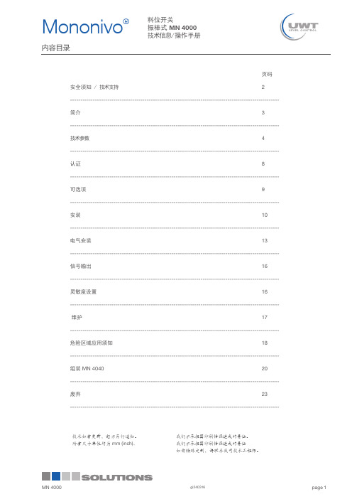
page 内容目录页码安全须知 / 技术支持2-----------------------------------------------------------------------------------------------------简介3-----------------------------------------------------------------------------------------------------技术参数4-----------------------------------------------------------------------------------------------------认证8-----------------------------------------------------------------------------------------------------可选项9-----------------------------------------------------------------------------------------------------安装10-----------------------------------------------------------------------------------------------------电气安装13-----------------------------------------------------------------------------------------------------信号输出16-----------------------------------------------------------------------------------------------------灵敏度设置16----------------------------------------------------------------------------------------------------- 维护17-----------------------------------------------------------------------------------------------------危险区域应用须知18-----------------------------------------------------------------------------------------------------组装 MN 404020-----------------------------------------------------------------------------------------------------废弃23-----------------------------------------------------------------------------------------------------技术如有更新,恕不另行通知。
微型 料位开关

微型料位开关全文共四篇示例,供读者参考第一篇示例:微型料位开关是一种用于检测和监控物料水平的设备,其小巧轻便的设计使其非常适合安装在狭小空间或者对装载有限的设备上。
这种开关通常由功能性部件和外壳组成,通过不同的工作原理来实现物料水平的检测。
它们被广泛应用于各种工业领域,如食品加工、化工、医药等,起到了非常重要的作用。
微型料位开关的种类繁多,主要可以分为浮球式、振动式、电容式等几类。
浮球式料位开关通过浮球的上升和下降来开关触点,当物料水位达到一定高度时,浮球会浮在物料表面,从而使开关触点闭合;而当物料下降到一定程度时,浮球则会沉下来,开关触点则会断开。
这种操作原理简单易懂,且结构稳定,因此在许多行业得到广泛运用。
振动式料位开关则是通过探头上的振动部件来实现物料水位的检测,当物料达到一定高度时,会阻碍振动部件的振动,触发开关动作;反之,在低水位时则不会有阻碍振动的物料存在,保持开关处于关闭状态。
这种类型的料位开关由于设计简洁、敏感度高、不易受外界干扰,因此被广泛应用于粉体、颗粒物料的检测领域。
电容式料位开关通过物料和电容传感器之间的介电常数差异来实现开关触点的动作。
当物料接触到电容传感器时,会改变电容传感器感应的电容值,从而触发开关的动作。
这种类型的料位开关具有精确的检测能力,可以应用于各种不同介电常数的物料,具有较强的通用性和灵活性。
微型料位开关在工业领域有着广泛的应用,可以用于物料的控制、监测和报警。
在食品加工行业,微型料位开关可以用于监测食品的水平,确保生产过程的顺利进行,同时也可以用于检测食品的残留物料,保障产品质量。
在化工行业,微型料位开关可以用于监测化工原料的储存和消耗情况,及时控制生产过程,确保生产安全。
在医药行业,微型料位开关可以用于监测药品的存储情况,精准控制药品的配料比例,保障产品质量。
虽然微型料位开关在工业领域有着广泛应用,但是在选择和安装时仍需注意一些问题。
需要根据物料的特性来选择适合的料位开关类型,确保其可以正确地检测物料水平。
球磨机料位控制使用说明书

目录一、概述 (3)二、型号及成套性 (4)三、结构形式、外形尺寸及重量 (5)四、硬件说明 (8)五、端子配线表 (10)六、技术规范 (12)1.信号规范2.正常工件条件七、软件说明 (13)八、料位测量 (17)1.测量原理2.测量过程3.标定过程4.料位显示和输出九、自动控制 (20)1.自动控制方式和选择2.与操作器的连接3.PID调节4.控制输出保护十、故障处理 (22)十一、售后服务 (24)附件:1.料位检测故障定位操作卡 (25)2.磨煤机料位监控系统缺陷调查表 (26)一、概述本产品为球磨机的通用控制设备,用于控制球磨机运行过程中的物料量和钢球量。
料位的定义:物料的体积与球磨机内部容积之百分比,即球磨机的物料充填率。
例如:物料质量G=7.5t,物料堆积比重d=0.96t/M³,根据球磨机结构尺寸计算出内部容积为V=30M³,则料位为:L=(G/d)/V=(7.5/0.96)/30≈26%本产品功能包括料位测量和给料自动控制两部分,料位测量是通过检测球磨机音频信号实现的;给料自动控制是通过将料位控制在一个定值上实现的。
通过将料位控制在一个定值上,球磨机电机的功率(或电流)的变化即反映了钢球充填率的变化。
因此,通过维持球磨机电机的功率(或电流)在一定值,即可实现钢球量的定值控制。
球磨机的工作效率取决于物料充填率和钢球充填率,即料位和钢球量。
应用本产品可以确定最佳料位和钢球量,并可以使球磨机始终保持在最佳工况,从而同时解决了球磨机的自动控制问题和节能降耗问题。
本产品广泛适用于电厂、矿山、水泥厂各种型号和工艺流程(风法、湿法、干法)的球磨机,并可产生显著的节能降耗效益,平均降低电耗20%,一台球磨机每年应用的直接经济效益平均达15万元。
用户单位技术人员可直接根据本说明书完成该产品的安装、调试、应用和维护,也可以向本公司经营部咨询。
二、型号及成套性1.TCS—200 球磨机料位监控装置产品有三种型号,见下表:2.STA—2球磨机音频传感器由球磨机专用音频探头、声学结构和安装结构三部分组成,是TCS —200的主要配套件,有两种型号,见下表:三、结构形式、外形尺寸及重量1.TCS—200球磨机料位监控装置的外形及结构形式、外形尺寸及重量:1.1外形图:1.2结构形式:1.3外形示意图:四.硬件说明 1. 硬件组成:硬件主要有五部分组成见上图:各部分之间由排线和播头连接,进行信号的传输。
夏米尔操作指南4
夏米尔操作指南4夏米尔ROBOFIL-XXX型操作指南状态信号行:GEO 路径转换激活时(MIR-ROT-INV)不亮,无功能激活时橙色 ALV 电极丝垂直校准时绿色ALP 电极丝工件校准时绿色GEN 脉冲电源接通时橙色CTC 电极丝短路时绿色ALM 数控在报警时红色UrG 紧急停止按钮按下时红色EXE 执行程序时黄色WIR 启动走丝时黄色显示当前使用的检查方式和时间MDI 键盘输入MEM 存储器JOG 手动Ready 准备就绪Start 执行Hold 中断用户参数SCF 缩放系数度 1 ROT 旋转角 0 MirX 对X轴镜像 0 MirY 对Y轴镜像 0 InvXY XY轴交换 0 TFE 考虑偏移 1 TER 考虑斜度角 1 ATH 自动重穿线ART 自动重启动SIM 空运行MLK 无移动模拟(程序校验)BLK 单段执行BLD 跳段有效,表示程序前有/的就不执行(如/M00) OSP 考虑可选停止制作:尹承效夏米尔ROBOFIL-XXX型操作指南BLK 打勾后,ISO程序单段执行OSP M01无效打勾后,M01有效(M01为暂停)BLD /开头的语句执行打勾后,/开头的语句跳过0、自动穿丝无效即断丝后不会自动穿丝ATH 1、断丝后回起割点自动穿丝再空走到断丝点切2、如果穿丝穿不进就直接加工下一个孔VSIM 空运行速度(6-900)1、机床坐标操做指令:SMA,X10 设制X轴机床坐标值为本10.00 SMA 设定机床坐标值X Y U V 同时为零MOV,X10 机床坐标系中的绝对移动将机床坐标X移到10处(注意无插补,各轴速度一样,路徑不是线性的) MOV XYUV都回零MOV,Z10 Z轴机床坐标移到10处绝对 Z轴不能同其他轴联动移动MVR 机床坐标的相对移动MVR,Z10 Z轴在现在的位置上向上移动10mm(不考虑转换、镜像、缩放,如果数控系统先前为绝对方式,移动后重新回到这一方式)制作:尹承效夏米尔ROBOFIL-XXX型操作指南CTR,X20 在此位置X轴向正方向加工20mm EDG,X-,X0.1252、工件坐标操作指令:SPA,X1 更新坐标SPA 同时更新XY的坐标为零MPA 绝对移动(不带值XY同时移动到零处) MPR 相对移动CPA 绝对加工CPR 相对加工3、预定义的移动GOH,Hh 按照工件高度H移动Z轴以定位喷嘴位 SEP,CPp 存储绝对坐标系中当前点的坐标p=点号,从0-5 GOP,p 移动到所定义的点位上,p=点号,从0-54、工艺和加工规准TEC<,表名> 激活含有准备使用的规准的工艺 WIR<,表名>激活准备使用的电极丝特性表HPA,h 修改当前高度h=新高度单位mm REX,Ee,(Hh)在所用工艺表中选择工艺规准Ee可选修改当高度(Hh) CLE(,c) 引入附加间隙(c=附加间隙,mm) CLE 设定附加间隙为零制作:尹承效夏米尔ROBOFIL-XXX型操作指南5、辅助功能AUX,m 辅助M功能(m=功能号)WTC 电极丝准备和切(拉)断WPR 断丝后的穿丝准备THR 自动穿丝(在WCT或WPR或人工丝准备之后) MDI模式常用指令:CT 相应的G\M代码SMA,XO,YO G74X0Y0 设定机床坐标的0,0点 SPA,XO,Y0 G92X0Y0 设定工件坐标的0,0点 MOV,X0,Y0 G75X0Y0 移动到机床坐标的0,0点 MVR,X2.0 X 方向相对移动2mm THD M60 穿丝WCT M50 剪丝SEP,CP1 G910 A1 设定当前点为1号点 GOP,1 G911 A1 从当前点移动到1号点EDG,Y,Y-0.125 Y方向对边,并把所对面设0CEN,R45 45度找孔中心 MID,R90 90度方向找中 CTR,X10 X方向相对切割10mm简单加工举例:TEC,LT25AREX,E2,H25制作:尹承效夏米尔ROBOFIL-XXX型操作指南CTR,X10程序执行:ZCL 加工计数器设回到零 SIM,I 激活(i=1) 不激活(i=0) EDG,s轴(,轴v) 找边CEN(,Xx)(,Yy)(,Rr) 找孔中心MID(,Xx)(,Yy)(,Rr) 在两个平行面之间找中GG00 快速移动G01 直线插补G02 顺时针圆弧插补G03 逆时针圆弧插补G04 暂停G09 准备停止一次移动到位 G10 指定偏移量/可选责程序跳步值 G11 自动加工顺序G17 编辑面选择G20 英制输入(英寸)G21 公制输入(mm)G22 存储行程极限功能ON(有效) G23 存储行程极限功能OFF G28 返回到第一参考点G29 从参考点返回到用户点 G30 返回到第二、第三、第四用户点 G32 存储当前点为用户第二、第三、第四参考点G33 设定用户点2,3,4G40 取消丝径补偿G41 电极丝左补偿G42 电极丝右补偿G46 最佳反向控制ONG47 最佳反向控制OFFG48 自动角部倒圆ONG49 自动角部倒圆OFFG50 取消斜度G51 左锥度G52 右锥度G53 在绝对坐标系中移动G61 恒定拐角半径制作:尹承效夏米尔ROBOFIL-XXX型操作指南G62 锥形拐角半径(最小) G63 锥形拐角半径(平均) G64 (最大) G65 宏调用(局部)G66 宏调用(全程)G67 取消宏调用(全程) G68 切割进给方式G69 准确停止方式G70 找边G71 找孔中心G72 找槽中心G73 电极丝校准和导向器设定循环 G74 设定测量点/机床坐标系设定 G75 在机床坐标系中定位 G76 定位-找边点类型1或2 G77 定位-测量点类型1、2或3 G78 定位-拐角点G79 计算工件倾斜角G86 取消支撑功能G87 “用支撑保留废芯”方式G88 “切除支撑”方式G90 绝对方式指令G91 相对G93 局部坐标系设定G94 恒速进给G95 伺服进给MM00 停止M01 可选停止(可用来建立支撑以保留废芯)M02 程序结束M06 穿丝水射流ON M07 上导电块退回ON M14 重穿丝块初始化 M15 锥度方式编成 M16 穿丝射水OFF M17 上导电块回退OFF M23 几何精度策略OFF M24 几何精度策略ON M27 保护策略OFF制作:尹承效夏米尔ROBOFIL-XXX型操作指南M28 一级粗加工策略ON M29 二级粗加工策略ON M30 程序结束和重绕 M31 预置计时器M32 检查水的离子度(电导率) M33 检查水的温度M34 工作液槽上水M35 放水M36 工作液槽位记忆+加载液位ON M37 加载液位OFF M40 空运行状态M42 走丝OFFM43 上、下冲液OFF M44 丝张力OFF M50 CUT 切丝M59 穿丝准备M60 穿丝M68 关闭循环泵M69 接通循环泵M70 轨迹返回功能M70 《执行有效》信号的管理 M71M73M74M80 加工状态M82 走丝开M83 下冲液开M87 存储功能1 ON M88 存储功能1 OFF M89 存储功能2 ON M90 存储功能2 OFF M91 遥控器报警有效 M92 遥控器报警无效 M93 遥控器报警接通ON M94 遥控器报警断开OFF M95 脉冲输出功能M96 完成加工M97 镜向反向加工M98 子程序调用M99 子程序结束制作:尹承效夏米尔ROBOFIL-XXX型操作指南穿丝射流水调整:EXE-service-calibration cyeles-wire calibration 激活卸下丝移动上加工头到相对于待加工工件所需的穿丝位置上接通穿丝射流水手动移动U/V轴以便使穿丝射流水对准下导向器的中心并在其周围分布均匀按memorize threading (记忆穿丝)ZUV 键,保存达到的位置存储UV位置;其值在穿丝操作中会自动用到。
- 1、下载文档前请自行甄别文档内容的完整性,平台不提供额外的编辑、内容补充、找答案等附加服务。
- 2、"仅部分预览"的文档,不可在线预览部分如存在完整性等问题,可反馈申请退款(可完整预览的文档不适用该条件!)。
- 3、如文档侵犯您的权益,请联系客服反馈,我们会尽快为您处理(人工客服工作时间:9:00-18:30)。
可靠
Rotonivo®
…运行自1988年!
…应用于白垩粉、沙粒及水泥超过 23 年 …这已远远超出我们的预料 ;-)
07/11 VBJ
Rotonivo®
…运行自1984年!
ROTONIVO
有42台阻旋料位开关已运行超过26年
(客户名称Mill)
这个纪录还在持续突破中…
ROTONIVO - 安装方式
密封面 密封平垫
Rotonivo® 3/6 – 最新改进
最新改进 RN3000/6000: ▪ 改进PTFE密封温度达250°C
双层密封
▪ 改进600°C应用密封
可用于水平安装 600°C 可选弹簧铰链桨叶 (用于较深安装孔)
ROTONIVO – 过程连接
在现有的安装孔上进行安装 • 各类螺纹及法兰连接标准 (BSP, NPT, ANSI, DIN) • 过程连接材质可选铝或不锈钢 (303) • 可选项: 高等级不锈钢(316 L) 适用于过程连接、保护管及测量桨叶材质 • 靴形桨叶适用于过程连接安装孔径为 1 ½“, 1 ¼“ and 1“, 弹簧铰链桨叶适用
FSH / FSL (开关逻辑)
ROTONIVO 电子部分
230VAC 带故障报警 Fail Safe Relay
ROTONIVO 电子部分
多功能供电电源 24VDC/115VAC/230VAC
将被取代为…
ROTONIVO 电子部分
通用供电电源 24VDC & 20..230VAC • 信号输出可调节继电器 • 可实现流动物料的开关量监测 • FSH / FSL (开关逻辑) • 自带加热器
☺
☺
☺
电力
☺
☺
复合物 / 纤维 ☺
☺
纸浆 & 纸业
☺
☺
采矿
☺
☺
ROTONIVO – 销售论据
• 严谨机械构造,德国工艺制造。 • 电机/减速箱齿轮模块化,更换方便。 • 电机—减速箱齿轮—传动部分双轴承密封。 • 可旋转壳体,安装方便。 • 安装调节方便,盖子附带防脱落螺丝及线路图。 • 配备两对电缆革兰头满足现场多电缆接口要求。 • 摩擦离合式电机保护减速箱齿轮。 • 过程连接处滚珠双轴承密封使外界粉尘与内部机械传动部件完全隔离
铸铝 带涂层, IP66
铸铝 带涂层, IP66 防燃防爆
铸铝 带涂层, IP66 防燃防爆 增安防爆
VIBRANIVO 认证分类
VN 1000 VN 2000 VN 4000 VN 5000
CE
FM/CSA general purpose
ATEX II 1/2 D
ATEX II 2G EEX de IIC
铸铝 带涂层, IP66
VN 4000 VN 5000 VN 6000
VN 5000 VN 6000
VN 5000 VN 6000
ATEX IEC-Ex GOST-R Ex RTN Ex FM CSA
ATEX IEC-Ex GOST-R Ex RTN Ex FM CSA
ATEX IEC-Ex GOST-R Ex RTN Ex FM CSA
ATEX II 1G and 1/2G EEx ia
IIC
FM DIP Cl. II, III Div. 1 Gr.
E,F,G
FM Cl. I Zone 1 AEx de IIC
认 证 FM XP Cl. I,II,III Div. 1 Gr.
A-G
FM Cl. I Zone 1 AEx d IIC
开。 • 附带传动杆径向密封圈 (Perbunan, Viton or Teflon) • 精巧紧凑的壳体,安装空间小 . • 螺纹 、法兰(过程连接) 多种可选,材质铝或不锈钢可选 • 所有型号生产周期极短 (2-4 days) • 应用于复杂工况,可定制特殊型号产品
ROTONIVO 电子部分
24VDC
RN 6000
RN 6000
ATEX II 2G Ex d IIC IEC-Ex d IIC T! Gb FM XP Cl. I Div. 1 Gr. B-D
Cl. I Zone 1 AEx d IIC CSA XP Cl. I Div. 1 Gr. B-D
Cl. I Zone 1 Ex d IIC
Rotonivo®
…阻旋料位开关!
特点 ▪ 适用于几乎所有固体物料 ▪ 简单可靠的测量方,免维护 ▪ 完全不受粉尘,介电常数,潮湿粘料,温度压力等因素影响 ▪ 适用于危险区域应用 (粉尘防爆)
技术特点 • 严谨精巧的设计,占用空间小 • 通用供电电压 (自动检测) • 安装简便,可旋转外壳 • 带涂层铸铝外壳 • 防护等级 IP 66 • 多种供电及过程连接供选择
的应用工况均有合适的选择
VIBRANIVO – 工作原理
是如何工作的?
晶体硅产生振动 振动驱动接收晶体硅 物料接触破坏振动 接收晶体硅信号衰减
VIBRANIVO – 安装
界面探测
壳体
VIBRANIVO - 壳体
系列
认证
规格
VN 1000 VN 2000 VN 4000
ATEX II IEC-Ex GOST-R Ex RTN Ex
ATEX II 2G Ex de IIC IEC-Ex de IIC T! Gb FM Cl. I Zone 1 AEx de IIC
带涂层铸铝, IP66 防燃防爆 螺纹式盖子
带涂层铸铝, IP66 防燃防爆, 增安防爆 螺纹式盖子
ROTONIVO – 根据密度选择测量桨 叶
ROTONIVO – 应用分类
ROTONIVO 电子部分
可选项:故障报警(旋转控制)
Failsafe (rotation control)
可监测到如下故障: • Motor(电机)
线路板感应
• Gear(减速箱齿轮)
• Electronic for motor power supply(电机供电
模块)
• Supply voltage failure(供电电源故障)
产品培训 料位开关
料位开关监测
电子 机械式
电子 机械式
选型标准
通用信息
选型标准 – 什么场合用什么测量 原理 ?
比较重的介质 (密度 >70g/l)
颗粒度>20mm
比较轻的介质 (密度<70g/l)
气泡膜类介质
温度 <150°C 温度 >150°C
压力 > 10bar
粘性较大的介质 过程潮湿度较大 污泥 & 泥浆 (导电) 固液分界面
VIBRANIVO 电子部分
多种可选项 • 供电电源:
• 通用电压 • 2-wire 无触点 • 2-wire 本安型
• 模块化设计,方便模块替换及备件维护 • 故障功能报警 (FSH or FSL) • 电子模块抗震性强 • 适用的信号输出有:
SPDT or DPDT PNP 4-20mA or 8/16mA NAMUR
VIBRANIVO 电子部分
灵敏度调节
VIBRANIVO 电子部分
通过电位器调节灵敏度 (VN1000/5000界面)
VIBRANIVO - NAMUR&8/16mA o r 4-20mA输出
振动强烈
振动微弱
振动停止
专利 8/16mA or 4-20mA电子模块 – 振动状态的自我控制信号输出 !
RN3004 I nstallation horizontal ly oblique
RN3003 Inst allation horiz ontally
卸料口安装 – RN3005
壳体
ROTONIVO - 壳体
系列 认证
规格
RN 4000
RN 3000
RN 6000
ATEX II 1/2 D IEC-Ex ta/tb IIIC T! Da/Db IP66 GOST-R Ex RTN Ex
RN 3000 series
RN 4000 series
RN 6000 series
农业
☺
☺
☺
建材
☺
☺
化工
☺
水泥
☺
☺
工 食品
☺
☺
业 石化
☺
医药
☺
☺
▪ RN 3000 适用于几乎所有
场合,除了气体防爆工况 ▪ RN 4000 仅适用于要求较低
的常规场合 ▪ RN 6000 适用于所有场合
(壳体较大)
塑料
2-wire 本安连接
NAMUR 输入
继电器 or 变送器 or 远程来自I/O变压器隔离栅,根据要求定制, e.g. Pep perl & Fuchs, MTL
VIBRANIVO 密封
紧密牢固的过程连接
• 专利性振动原理 • 抗冲击的压电构造 • 完全焊接延展 (VN1000/20
00/5000/6000) • VN4000延展部分无焊点 • 自紧锥螺纹
ATEX II 1/2 D IEC-Ex ta/tb IIIC T! Da/Db IP66 GOST-R Ex RTN Ex
ATEX 1/2D FM Cl. II, III Div. 1 Gr. E,F,G CSA Cl. II, III Div.1 Gr. E,F,G
塑料 PA 带涂层铸铝, IP66 带涂层铸铝, IP66
ROTONIVO 密封材质- 选型
FPM Sealing PTFE Sealing
Rotonivo® 3/6 – 最新改进
最新改进 RN3000/6000: • 密封平垫带密封面可选择 (选项)
• (替代传统的标准的Teflon生料带密封方式)